EP4040052A1 - System with assembly of heating modules - Google Patents
System with assembly of heating modules Download PDFInfo
- Publication number
- EP4040052A1 EP4040052A1 EP22154921.5A EP22154921A EP4040052A1 EP 4040052 A1 EP4040052 A1 EP 4040052A1 EP 22154921 A EP22154921 A EP 22154921A EP 4040052 A1 EP4040052 A1 EP 4040052A1
- Authority
- EP
- European Patent Office
- Prior art keywords
- module
- wall
- air
- flow
- electric heating
- Prior art date
- Legal status (The legal status is an assumption and is not a legal conclusion. Google has not performed a legal analysis and makes no representation as to the accuracy of the status listed.)
- Pending
Links
Images


Classifications
-
- F—MECHANICAL ENGINEERING; LIGHTING; HEATING; WEAPONS; BLASTING
- F24—HEATING; RANGES; VENTILATING
- F24D—DOMESTIC- OR SPACE-HEATING SYSTEMS, e.g. CENTRAL HEATING SYSTEMS; DOMESTIC HOT-WATER SUPPLY SYSTEMS; ELEMENTS OR COMPONENTS THEREFOR
- F24D13/00—Electric heating systems
- F24D13/02—Electric heating systems solely using resistance heating, e.g. underfloor heating
- F24D13/022—Electric heating systems solely using resistance heating, e.g. underfloor heating resistances incorporated in construction elements
- F24D13/024—Electric heating systems solely using resistance heating, e.g. underfloor heating resistances incorporated in construction elements in walls, floors, ceilings
-
- F—MECHANICAL ENGINEERING; LIGHTING; HEATING; WEAPONS; BLASTING
- F24—HEATING; RANGES; VENTILATING
- F24H—FLUID HEATERS, e.g. WATER OR AIR HEATERS, HAVING HEAT-GENERATING MEANS, e.g. HEAT PUMPS, IN GENERAL
- F24H3/00—Air heaters
- F24H3/02—Air heaters with forced circulation
- F24H3/04—Air heaters with forced circulation the air being in direct contact with the heating medium, e.g. electric heating element
- F24H3/0405—Air heaters with forced circulation the air being in direct contact with the heating medium, e.g. electric heating element using electric energy supply, e.g. the heating medium being a resistive element; Heating by direct contact, i.e. with resistive elements, electrodes and fins being bonded together without additional element in-between
- F24H3/0411—Air heaters with forced circulation the air being in direct contact with the heating medium, e.g. electric heating element using electric energy supply, e.g. the heating medium being a resistive element; Heating by direct contact, i.e. with resistive elements, electrodes and fins being bonded together without additional element in-between for domestic or space-heating systems
-
- F—MECHANICAL ENGINEERING; LIGHTING; HEATING; WEAPONS; BLASTING
- F24—HEATING; RANGES; VENTILATING
- F24H—FLUID HEATERS, e.g. WATER OR AIR HEATERS, HAVING HEAT-GENERATING MEANS, e.g. HEAT PUMPS, IN GENERAL
- F24H9/00—Details
- F24H9/0052—Details for air heaters
- F24H9/0057—Guiding means
- F24H9/0063—Guiding means in air channels
-
- F—MECHANICAL ENGINEERING; LIGHTING; HEATING; WEAPONS; BLASTING
- F24—HEATING; RANGES; VENTILATING
- F24H—FLUID HEATERS, e.g. WATER OR AIR HEATERS, HAVING HEAT-GENERATING MEANS, e.g. HEAT PUMPS, IN GENERAL
- F24H9/00—Details
- F24H9/02—Casings; Cover lids; Ornamental panels
-
- Y—GENERAL TAGGING OF NEW TECHNOLOGICAL DEVELOPMENTS; GENERAL TAGGING OF CROSS-SECTIONAL TECHNOLOGIES SPANNING OVER SEVERAL SECTIONS OF THE IPC; TECHNICAL SUBJECTS COVERED BY FORMER USPC CROSS-REFERENCE ART COLLECTIONS [XRACs] AND DIGESTS
- Y02—TECHNOLOGIES OR APPLICATIONS FOR MITIGATION OR ADAPTATION AGAINST CLIMATE CHANGE
- Y02B—CLIMATE CHANGE MITIGATION TECHNOLOGIES RELATED TO BUILDINGS, e.g. HOUSING, HOUSE APPLIANCES OR RELATED END-USER APPLICATIONS
- Y02B30/00—Energy efficient heating, ventilation or air conditioning [HVAC]
Definitions
- the present invention relates to a system comprising a set of heating modules intended to be fixed to a substantially vertical support, in particular for heating a room.
- each heating tile thermally influences the neighboring heating tile as a whole. Therefore, each tile must not only dissipate the calories it generates but also part of the calories generated by the neighboring tiles.
- the heating tiles are arranged vertically against a wall and therefore one above the other, this problem is moreover accentuated since the heat dissipated by a tile arranged in the lower part of the heating assembly propagates vertically to the tiles arranged at the above him.
- the invention notably proposes a solution to the problem of thermal influence between heating tiles arranged vertically.
- the subject of the invention is a system comprising a heating assembly and a substantially vertical support to which said heating assembly is fixed, the heating assembly comprising at least two electric heating modules arranged against the vertical support, one of the modules , said upper module, being arranged at a higher level than that of the other module, said lower module, each electric heating module comprising a body which encloses at least one electric heating element and which is delimited externally by a wall, the wall being provided, on the one hand, with one or more air inlet openings arranged in its lower part and, on the other part, from one or more air outlet openings arranged in its upper part for the circulation of an upward flow of air inside said body, in particular on said at least one electrical heating element to be cooled, at the least part of the air outlet opening(s) of each module being oriented so as to deflect at least part of the flow of air leaving said module in such a way that, for the lower and upper modules, said at least one part of the air flow heated by said at least one electric heating element and leaving the
- the oriented air outlet opening part By thus orienting at least part of the air outlet opening or openings of each module (called the oriented air outlet opening part), the part of the air flow which is heated during the passage along said at least one electric heating element and which exits from the module through this oriented air outlet opening part is deviated from its vertical upward trajectory which, normally, would lead the flow directly to the upper module.
- the flow of hot air is deflected away from the upper module, i.e. it is directed towards the front of the module, as opposed to the rear of the module which faces the mounting bracket from the whole. More particularly, the airflow is directed either substantially horizontally or with an oblique upward inclination. In this way, the hot air flow does not heat the upper module. This configuration thus makes it possible to limit the thermal influence between the modules.
- the arrangement of the modules in the arrangement of the assembly can take different forms: for example, in the arrangement the lower module can be arranged directly below another module (vertical to the module above ), namely the upper module, and it may optionally be arranged adjacent to another module located at the same level or whose level is higher than its own (according to a front view of the arrangement against the substantially vertical support ).
- the lower module can be arranged in the arrangement so that the upper module is offset horizontally with respect to the lower module and is thus only partly under the upper module (according to a front view of the arrangement against the substantially vertical support).
- the lower module can moreover also be partly under at least one other upper module.
- the external shape of the bodies of modules influences the way the modules can be arranged adjacent to each other covering all or part of the substantially vertical support (above, below and on the sides).
- a system according to a first embodiment of the invention comprises a heating assembly 12 and a substantially vertical support 14, here a wall of a room, to which the assembly is fixed.
- the heating assembly 12 generally comprises several electrical heating modules, one of which is placed at a height greater than the height of the other module.
- the lower module 16, called the lower module is represented in full on the figure 1 and the top module 18, called the top module, is shown partially in dotted lines.
- the upper module 18 can be arranged directly above the lower module 16 in a vertical arrangement.
- the upper module 18 can be offset horizontally with respect to the position of the lower module 16 so as to be only partly above the lower module, at least one other upper module can also be partly above the same module lower 16.
- the figure 8 represents, in another embodiment, a heating assembly which comprises several electric heating modules arranged at different sides of each other and, for example, arranged plumb with each other.
- the electric heating modules of a heating assembly are generally all identical.
- the electrical heating modules of the same heating assembly may, at least for some of them, differ from one module to another, insofar as the lower modules of the assembly all make it possible to reduce the thermal influence they have on the upper modules of the assembly.
- the external shapes of the modules in front view can adopt any what geometry: square, rectangular, triangular, diamond-shaped, circle, ellipse or a non-regular geometric shape.
- the module 16 (the configuration of the module 18 is identical to that of the module 16) comprises a closed body 20 which contains at least one electric heating element or heating body 22 (here a single heating element is shown). It may for example be one or more electric heating resistors. The fixing of the electric heating element inside the body is not shown in the figure for the sake of simplicity. It may for example be arms connected to the internal face of the body.
- the body 20 of the module generally comprises a rear cover 24 which is shaped so as to form an open box on the front of the module (opposite to the support 14) to house the heating element 22 and a front wall 26 which closes, the manner of a front technical facade, the front opening of the case.
- the convex outer shape of the rear cover 24 is arranged facing the wall bracket 14 and the cover is fixed to the support by means of a conventional attachment device 28 (eg fixing lugs and screws or similar fixing devices) .
- the closed body 20 is thus delimited by an outer wall, part of which is formed by the front wall 26 and the remaining part of the wall is formed by the wall of the rear cover 24, called the rear wall.
- the outer wall delimiting the body of the module 16 is provided with two types of openings: one or more air inlet openings (O1, O2), generally arranged in the lower part of the body and one or more air outlet openings. air (O3), generally arranged in the upper part of the body.
- air inlet openings are arranged in the lower part of the rear wall of the cover 24, in particular in adjacent portions of this wall.
- the air inlet openings are made in a horizontal portion (openings O1) and in an adjacent inclined portion (openings O2) of the rear wall, thus allowing air to enter as illustrated by the arrows .
- the location, number and configuration of the air intake opening(s) may vary depending on module configuration.
- the opening or openings O1 can be while the opening or openings O2 are preserved or vice versa.
- the air outlet opening(s) O3 are here arranged in the upper part of the front wall 26, close to the upper horizontal portion of the rear cover 24.
- the air outlet opening(s) in the upper part of the front wall 26 which is here substantially vertical, the upward flow of air which circulates inside the body of the module, after having entered through the air inlet openings O1, O2 and having licked the heating element 22, leaves the body through the air outlet opening or openings O3 which have a substantially horizontal orientation.
- the flow of hot air leaving through these openings and which thus evacuates part of the heat dissipated by the heating body is thus directed towards the front of the module 16, away from this module and from the upper module 18 as represented by the arrow on the figure 1 .
- air outlet opening or openings O3 can alternatively be oriented inclined upwards as long as the angle of inclination remains less than 90° so that the outgoing hot air flow does not come into contact of the upper module 18.
- the system 30 of the figure 2 takes over the system 10 of the figure 1 (this will therefore not be described again) and adds an additional wall 32 placed in front of the front wall 26 and at a distance from the latter, thus forming a front facade for the body of the module 16'.
- a facade is aesthetic in nature and may include a decorative visual aspect (color, shape, pattern, texture, etc.).
- this facade can fulfill a technical function.
- this facade can fulfill an aesthetic function and a technical function.
- the additional wall 32 is for example fixed to the body 20 of the module 16', for example to the front wall 26, by means of one or more fixing elements not shown here for the sake of simplicity.
- the upper 18' module also has an additional wall forming the front facade.
- the additional wall 32 here has dimensions which are slightly larger than those of the body (at least in the vertical direction) in order to hide the latter.
- the dimensions of this wall in the horizontal direction can be equal to or also be slightly greater than those of the body.
- the additional wall 32 has dimensions smaller than those of the front wall. Such a configuration is for example illustrated on the figure 7 which will be described later.
- the additional wall 32 generally has a substantially planar shape as shown in the figure 2 .
- the outer contour of this wall in front view can, like that of the modules, adopt different geometries, as mentioned above for the modules.
- the system 40 comprises a heating assembly with at least one lower heating module 42 and an upper heating module 44 shown partially in dotted lines.
- the two modules are fixed to the substantially vertical support 14 in an identical manner to the embodiments of the figures 1 and 2 .
- the lower module 42 (just like the upper module 44) comprises a body 46 whose general shape is substantially the same as that of the body 20 of the figure 1 and which is formed by the assembly of an open rear cover 50 and a front wall 48 close this cover.
- the body also comprises at least one electric heating element identical to the electric heating element 22 of the figure 1 .
- the air inlet openings O1 and O2 are identical to those of the figure 1 .
- the body of the module 42 contains an internal deflector 52 arranged so as to deflect the upward flow of air which enters the module through the air inlet openings O1 and O2.
- This deflector 52 takes the form of an internal wall which separates the space internal to the body into a first zone, called the front, where the electric heating element 22 is housed and a second zone, called the rear, devoid of an electric heating element. and therefore a source of heat.
- the internal deflector generally has an inverted L shape, the horizontal bar 52a of which is arranged in the upper part of the body against the front wall 48 and the vertical or substantially vertical bar 52b of which extends substantially vertically in the direction of the lower part. of the body as shown in the picture 3 .
- the upward flow of air at ambient temperature which enters the body through the air inlet opening(s) O1 and O2 is separated by this deflector into a first upward flow which is diffused in the first zone and a second flow which is broadcast in the second zone.
- the first upward flow of air is guided by the deflector 52 in the first zone and meets the heating element 22 which it skirts on all sides while cooling it.
- This heated airflow is then deflected substantially horizontally by the upper part 52a of the deflector and is thus forced to use the air outlet opening(s) O3 to escape from the module in an outlet direction which is not directed towards the upper module.
- the second upward flow of air is guided by the deflector 52 in the second zone which runs along the rear wall of the cover 50 and rises along the latter until it reaches the upper part of the second zone where one or more openings of O4 air outlet are arranged in the substantially horizontal portion of the upper part of the rear bonnet.
- This second flow of air is hardly heated by the zone during its upward path insofar as the internal deflector acts as a thermal screen between the two zones.
- This second flow of air can therefore be evacuated from the module in a substantially vertical direction which it brings directly to the upper module, in particular at one or more of its air inlet openings O1, O2.
- the air outlet opening(s) O4 are separated from the air outlet opening(s) O3 by the internal deflector 52, in particular its upper part 52a.
- the system 60 of the figure 4 takes over the system 40 of the picture 3 (this will therefore not be described again) and adds an additional wall 62 identical to the wall 32 of the mode of the picture 2 .
- the elements, characteristics, functions associated with the embodiment of the picture 3 and to the wall 32 of the embodiment of the figure 2 and the related advantages are retained and will not be described again here.
- the system 60 includes the lower module 64 identical to the lower module 42 of the picture 3 without the additional wall 62 and the upper module 66 identical to the upper module 44 of the picture 3 .
- the system 70 of the fifth embodiment of the figure 5 differs from the mode of figure 4 by the inclination of the upper part of the additional wall forming the front facade 72 of the lower module 74.
- the spacing between the additional wall 72 and the front wall 48 of the body widens from the lower part of the body to the upper part of it.
- the flow of hot air leaving the air outlet opening(s) O3 is thus deflected from its substantially horizontal trajectory by the inclined upper part of the wall 72 which directs the flow of air upwards, in an inclined direction. away from the upper module 76.
- the dimensions of the additional wall 72 in particular its height, can be increased compared to the modes of the figure 2 and 4 insofar as the additional adjacent walls of two lower and upper modules are not likely to come into contact with each other.
- the wall 72 of the lower module 74 can thus partly cover the additional wall of the upper module 76 in the manner of tiles.
- the covering occurs only over a small portion of the height of the additional walls.
- the inclination of the additional wall 72 can vary between a value of a few degrees (eg: 5°) with respect to the substantially vertical arrangement of the front wall 48 up to a higher value of the order of 10 °, 15°, 20° or more depending on the configuration of the modules and the heating assembly. More generally, the additional wall 72 is inclined relative to the front wall 48 by an angle of a value between 1 and 45°, preferably between 5 and 35°, even more preferably between 10 and 30° .
- the system 80 of the sixth embodiment of the figure 6 differs from system 70 of the figure 5 by the inclination of the front wall 82 of the body 84 of the module.
- the body 84 of the module is wider in its upper part than in its lower part (the width of the body is engaged horizontally in a direction perpendicular to the plane of the support 14.
- This inclination of the front wall 82 makes it possible to deflect more than in the mode of figure 5 the flow of hot air exiting through the air outlet opening(s) O3 of the lower module.
- the flow of hot air leaving this or these openings is oriented downwards (the inclination is all the greater as the wall 82 is inclined), which distances it even further from the upper module.
- the inclined front wall 82 also makes it possible, by its inclination, to guide this air flow, together with the additional wall 72, even further from the upper module than on the figure 5 .
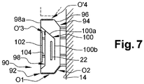
- the system 90 of the seventh embodiment of the figure 7 differs from the systems of previous modes in several aspects.
- the module 92 comprises a body 94 which includes a rear cover 96 closed by a front wall 98.
- the body 94 contains one or more electric heating elements 22, an internal deflector 100 which performs the same function as the internal deflector 52 of the previous modes, one or more air inlet openings O1, O2 in the lower part of the body, one or more air outlet openings O′3 in the upper part of the front wall 98 and one or more air outlet openings O '4 in the substantially horizontal upper part of the rear cover 96.
- the front wall 98 has a generally concave shape oriented towards the outside of the body so as to guide outwardly the part of the flow of hot air leaving the module through the air outlet opening(s) O′3 and which is deflected, in this case by the deflector 100.
- This part of the hot air flow corresponds to the first air flow which propagates in the first zone of the body where the heating element 22 is housed, as already explained below. above in reference to the mode of the picture 3 .
- the front wall 98 extends beyond the concavity by a substantially planar peripheral edge 98a which is arranged on the figure 7 in a substantially vertical plane.
- the peripheral edge 98a can extend over the entire periphery of the front wall or only over part of it.
- Internal baffle 100 is mounted on the internal side of wall 98.
- the front wall 98 has the general shape of a bowl, for example a shape with an essentially frustoconical appearance, the air outlet opening(s) O′3 being made in the substantially planar portion forming the bottom of the truncated cone .
- the frustoconical shape is extended externally by the substantially flat peripheral edge 98a.
- the internal deflector 100 has a first portion 100a which follows the inclination of the portion inclined truncated cone and a second portion 100b falling substantially vertically.
- the module also comprises an additional wall 102 which is arranged in front of the front wall 98, at a distance from the latter, fixed to the latter for example by arms 104, but which, unlike the previous modes, is positioned flush relative to the peripheral edge 98a of the front wall.
- the additional wall 102 therefore does not protrude with respect to the body 94 of the module as for the other modes but is circumscribed in the external envelope of the body 94 and therefore does not induce additional bulk on the front face of the module.
- the design of this module is more compact than that of the other embodiments.
- the system 110 comprises a heating assembly 112 comprising several electrical heating modules 114 fixed to a substantially vertical support, not shown, by means of a plurality of attachment devices 116 which are here all identical to one another from one module to the other.
- the modules 114 are here all identical and are arranged one above the other in a vertical assembly in a view perpendicular to the plane of the substantially vertical support to which the heating assembly is attached. In front view, that is to say in a plane parallel to the plane of the substantially vertical support, the modules may have a horizontal offset relative to each other without this affecting their difference in dimension or altitude.
- Each module 114 presents here the configuration of module 70 of the figure 5 with the exception, however, of the internal deflector 118 which here is positioned by its flat upper part against the flat upper part of the rear cover of the module.
- the air outlet opening(s) O4 of the figure 5 referenced here O"4 are offset towards the rear of the cover on the figure 8 , set back from the front wall.
- the other details of the realization of the figure 5 are not listed on the figure 8 for the sake of simplicity.
- the inclined upward arrows which are each arranged in the geometric gap formed between two neighboring modules (lower module and upper module) each represent the airflow deflected heat which escapes from the lower module away from the upper module in order to limit, or even avoid, thermally influencing the upper module.
Abstract
L'invention concerne un système (10) comprenant un ensemble chauffant (12) et un support sensiblement vertical (14) auquel est fixé ledit ensemble chauffant, l'ensemble chauffant (12) comprenant un module supérieur (18), étant disposé à une cote supérieure à celle d'un autre module inférieur (18), chaque module électrique chauffant comprenant un corps (20) qui renferme au moins un élément électrique chauffant (22) et qui est délimité extérieurement par une paroi, la paroi étant pourvue, d'une part, d'une ou de plusieurs ouvertures d'entrée d'air aménagées dans sa partie basse et, d'autre part, d'une ou de plusieurs ouvertures de sortie d'air disposées dans sa partie haute pour la circulation d'un flux d'air ascendant à l'intérieur dudit corps, notamment sur ledit au moins un élément électrique chauffant à refroidir.

Description
La présente invention concerne un système comprenant un ensemble de modules chauffants destinés à être fixés à un support sensiblement vertical, notamment pour le chauffage d'un local.The present invention relates to a system comprising a set of heating modules intended to be fixed to a substantially vertical support, in particular for heating a room.
On connaît du document
Cette conception d'ensemble chauffant est confrontée à la problématique de la dissipation thermique due à la chauffe des résistances électriques mais ceci n'est toutefois pas abordé dans ce document.This heating assembly design is confronted with the problem of heat dissipation due to the heating of the electrical resistors, but this is however not addressed in this document.
Cette problématique se pose notamment dans la mesure où chaque carreau chauffant influence thermiquement le carreau chauffant voisin dans l'ensemble. De ce fait, chaque carreau doit non seulement dissiper les calories qu'il génère mais également une partie des calories générées par les carreaux voisins. Lorsque les carreaux chauffant sont disposés verticalement contre un mur et donc les uns au-dessus des autres, ce problème est d'ailleurs accentué puisque la chaleur dissipée par un carreau disposé en partie basse de l'ensemble chauffant se propage verticalement aux carreaux disposés au-dessus de lui.This problem arises in particular insofar as each heating tile thermally influences the neighboring heating tile as a whole. Therefore, each tile must not only dissipate the calories it generates but also part of the calories generated by the neighboring tiles. When the heating tiles are arranged vertically against a wall and therefore one above the other, this problem is moreover accentuated since the heat dissipated by a tile arranged in the lower part of the heating assembly propagates vertically to the tiles arranged at the above him.
L'invention propose notamment une solution au problème d'influence thermique entre des carreaux chauffants disposés verticalement.The invention notably proposes a solution to the problem of thermal influence between heating tiles arranged vertically.
À cet effet, l'invention a pour objet un système comprenant un ensemble chauffant et un support sensiblement vertical auquel est fixé ledit ensemble chauffant, l'ensemble chauffant comprenant au moins deux modules électriques chauffants disposés contre le support vertical, l'un des modules, dit module supérieur, étant disposé à une cote supérieure à celle de l'autre module, dit module inférieur, chaque module électrique chauffant comprenant un corps qui renferme au moins un élément électrique chauffant et qui est délimité extérieurement par une paroi, la paroi étant pourvue, d'une part, d'une ou de plusieurs ouvertures d'entrée d'air aménagées dans sa partie basse et, d'autre part, d'une ou de plusieurs ouvertures de sortie d'air disposées dans sa partie haute pour la circulation d'un flux d'air ascendant à l'intérieur dudit corps, notamment sur ledit au moins un élément électrique chauffant à refroidir, au moins une partie de la ou des ouvertures de sortie d'air de chaque module étant orientée de manière à dévier au moins une partie du flux d'air sortant dudit module de telle manière que, pour les modules inférieur et supérieur, ladite au moins une partie du flux d'air chauffée par ledit au moins un élément électrique chauffant et sortant du module inférieur est déviée en éloignement du module supérieur.To this end, the subject of the invention is a system comprising a heating assembly and a substantially vertical support to which said heating assembly is fixed, the heating assembly comprising at least two electric heating modules arranged against the vertical support, one of the modules , said upper module, being arranged at a higher level than that of the other module, said lower module, each electric heating module comprising a body which encloses at least one electric heating element and which is delimited externally by a wall, the wall being provided, on the one hand, with one or more air inlet openings arranged in its lower part and, on the other part, from one or more air outlet openings arranged in its upper part for the circulation of an upward flow of air inside said body, in particular on said at least one electrical heating element to be cooled, at the least part of the air outlet opening(s) of each module being oriented so as to deflect at least part of the flow of air leaving said module in such a way that, for the lower and upper modules, said at least one part of the air flow heated by said at least one electric heating element and leaving the lower module is deflected away from the upper module.
En orientant ainsi au moins une partie de la ou des ouvertures de sortie d'air de chaque module (appelée partie d'ouverture de sortie d'air orientée), la partie du flux d'air qui est chauffée lors du passage le long dudit au moins un élément électrique chauffant et qui sort du module par cette partie d'ouverture de sortie d'air orientée est déviée de sa trajectoire ascendante verticale qui, normalement, conduirait le flux directement sur le module supérieur. Le flux d'air chaud est dévié en s'éloignant du module supérieur, c'est-à-dire qu'il est dirigé vers l'avant du module, par opposition à l'arrière du module qui fait face au support de fixation de l'ensemble. Plus particulièrement, le flux d'air est dirigé soit sensiblement horizontalement soit avec une inclinaison en biais vers le haut. De cette manière, le flux d'air chaud ne vient pas chauffer le module supérieur. Cette configuration permet ainsi de limiter l'influence thermique entre les modules.By thus orienting at least part of the air outlet opening or openings of each module (called the oriented air outlet opening part), the part of the air flow which is heated during the passage along said at least one electric heating element and which exits from the module through this oriented air outlet opening part is deviated from its vertical upward trajectory which, normally, would lead the flow directly to the upper module. The flow of hot air is deflected away from the upper module, i.e. it is directed towards the front of the module, as opposed to the rear of the module which faces the mounting bracket from the whole. More particularly, the airflow is directed either substantially horizontally or with an oblique upward inclination. In this way, the hot air flow does not heat the upper module. This configuration thus makes it possible to limit the thermal influence between the modules.
On notera que la disposition des modules dans l'agencement de l'ensemble peut prendre différentes formes : par exemple, dans l'agencement le module inférieur peut être disposé directement en dessous d'un autre module (à l'aplomb du module du dessus), à savoir le module supérieur, et il peut éventuellement être disposé de manière adjacente à un autre module situé à la même cote ou dont la cote est supérieure à la sienne (suivant une vue de face de l'agencement contre le support sensiblement vertical). Le module inférieur peut être disposé dans l'agencement de manière à ce que le module supérieur soit décalé horizontalement par rapport au module inférieur et ne soit ainsi qu'en partie sous le module supérieur (suivant une vue de face de l'agencement contre le support sensiblement vertical). Le module inférieur peut d'ailleurs être également en partie sous au moins un autre module supérieur. La forme externe des corps des modules influence la manière dont les modules peuvent être disposés de manière adjacente les uns par rapport aux autres en couvrant tout ou partie du support sensiblement vertical (au-dessus, en dessous et sur les côtés).It will be noted that the arrangement of the modules in the arrangement of the assembly can take different forms: for example, in the arrangement the lower module can be arranged directly below another module (vertical to the module above ), namely the upper module, and it may optionally be arranged adjacent to another module located at the same level or whose level is higher than its own (according to a front view of the arrangement against the substantially vertical support ). The lower module can be arranged in the arrangement so that the upper module is offset horizontally with respect to the lower module and is thus only partly under the upper module (according to a front view of the arrangement against the substantially vertical support). The lower module can moreover also be partly under at least one other upper module. The external shape of the bodies of modules influences the way the modules can be arranged adjacent to each other covering all or part of the substantially vertical support (above, below and on the sides).
Selon d'autres caractéristiques possibles :
- la paroi délimitant le corps de chaque module comporte une paroi frontale opposée à une paroi arrière qui fait face au support sensiblement vertical, ladite au moins une partie de la ou des ouvertures de sortie d'air qui est orientée de manière à dévier au moins une partie du flux d'air sortant du module étant aménagée dans la partie supérieure de la paroi frontale;
- chaque module comporte une paroi supplémentaire disposée devant la paroi frontale du corps du module et à distance de ladite paroi de manière à former une façade avant pour le corps;
- la paroi supplémentaire formant façade avant est inclinée par rapport à la paroi frontale de telle manière que l'écartement entre ladite paroi supplémentaire et la paroi frontale est plus grand en partie haute du corps qu'en partie basse ;
- la paroi supplémentaire formant façade avant est inclinée par rapport à la paroi frontale d'un angle d'une valeur située entre 1 et 45°, de préférence entre 5 et 35°, de manière encore préférée entre 10 et 30° ; - la paroi supplémentaire formant façade avant est perforée dans son épaisseur sur au moins une partie de sa surface;
- la paroi supplémentaire formant façade avant possède des dimensions qui sont égales ou supérieures à celles de la paroi frontale;
- la paroi frontale présente une forme générale concave orientée vers l'extérieur du corps de manière à guider vers l'extérieur ladite au moins une partie du flux d'air sortant du module et qui est déviée;
- que le corps de chaque module renferme un déflecteur interne qui est disposé de manière à dévier le flux d'air ascendant qui traverse la zone du corps où est logé ledit au moins un élément électrique chauffant en direction de ladite au moins une partie de la ou des ouvertures de sortie d'air qui est orientée de manière à dévier au moins une partie du flux d'air sortant du module et qui est appelée partie d'ouverture de sortie d'air orientée ;
- le déflecteur interne sépare le flux d'air ascendant entrant dans le corps par la ou les ouvertures d'entrée d'air, d'une part, en un premier flux d'air ascendant qui traverse une première zone où est logé ledit au moins un élément électrique chauffant et, d'autre part, en un second flux d'air ascendant qui traverse une deuxième zone du corps, ledit déflecteur interne guidant ce second flux d'air ascendant en direction d'une ou de plusieurs autres ouvertures de sortie d'air qui sont disposées dans une partie haute de la paroi du corps sensiblement horizontale et qui sont séparées de la partie d'ouverture de sortie d'air orientée par le déflecteur interne ;
- le déflecteur interne a une fonction d'écran thermique entre la première zone où est logé ledit au moins un élément électrique chauffant et la deuxième zone du corps traversée par le second flux d'air.
- the wall delimiting the body of each module comprises a front wall opposite a rear wall which faces the substantially vertical support, said at least part of the air outlet opening or openings which is oriented so as to deflect at least one part of the air flow exiting the module being arranged in the upper part of the front wall;
- each module comprises an additional wall arranged in front of the front wall of the body of the module and at a distance from said wall so as to form a front facade for the body;
- the additional wall forming the front facade is inclined with respect to the front wall in such a way that the distance between said additional wall and the front wall is greater in the upper part of the body than in the lower part;
- the additional wall forming the front facade is inclined relative to the front wall by an angle of a value between 1 and 45°, preferably between 5 and 35°, more preferably between 10 and 30°; - the additional wall forming the front facade is perforated in its thickness over at least part of its surface;
- the additional wall forming the front facade has dimensions which are equal to or greater than those of the front wall;
- the front wall has a generally concave shape oriented towards the outside of the body so as to guide said at least part of the flow of air leaving the module and which is deflected towards the outside;
- that the body of each module contains an internal deflector which is arranged in such a way as to deflect the upward flow of air which crosses the area of the body where said at least one electric heating element is housed in the direction of said at least part of the or air outlet openings which is oriented so as to deflect at least a part of the air flow exiting the module and which is referred to as the oriented air outlet opening part;
- the internal baffle separates the upward airflow entering the body through the air inlet opening(s), on the one hand, into a first upward airflow which passes through a first zone where said at least one electric heating element is housed and, on the other hand, in a second upward flow of air which passes through a second zone of the body, said internal deflector guiding this second upward flow of air in the direction one or more other air outlet openings which are arranged in an upper part of the wall of the substantially horizontal body and which are separated from the air outlet opening part oriented by the internal deflector;
- the internal deflector has a heat shield function between the first zone where said at least one electric heating element is housed and the second zone of the body through which the second air flow passes.
D'autres caractéristiques et avantages apparaîtront au cours de la description qui va suivre, donnée uniquement à titre d'exemple non limitatif et faite en référence aux dessins annexés, sur lesquels :
- [
Fig. 1 ] LaFigure 1 est une vue schématique en coupe de côté d'un système selon un premier mode de réalisation de l'invention ; - [
Fig. 2 ] LaFigure 2 est une vue schématique en coupe de côté d'un système selon un deuxième mode de réalisation de l'invention ; - [
Fig. 3 ] LaFigure 3 est une vue schématique en coupe de côté d'un système selon un troisième mode de réalisation de l'invention ; - [
Fig. 4 ] LaFigure 4 est une vue schématique en coupe de côté d'un système selon un quatrième mode de réalisation de l'invention ; - [
Fig. 5 ] LaFigure 5 est une vue schématique en coupe de côté d'un système selon un cinquième mode de réalisation de l'invention ; - [
Fig. 6 ] LaFigure 6 est une vue schématique en coupe de côté d'un système selon un sixième mode de réalisation de l'invention ; - [
Fig. 7 ] LaFigure 7 est une vue schématique en coupe de côté d'un système selon un septième mode de réalisation de l'invention ; - [
Fig. 8 ] LaFigure 8 est une vue schématique en coupe de côté d'un système selon un huitième mode de réalisation de l'invention.
- [
Fig. 1 ] TheFigure 1 is a schematic side sectional view of a system according to a first embodiment of the invention; - [
Fig. 2 ] TheFigure 2 is a schematic side sectional view of a system according to a second embodiment of the invention; - [
Fig. 3 ] TheFigure 3 is a schematic side sectional view of a system according to a third embodiment of the invention; - [
Fig. 4 ] TheFigure 4 is a schematic side sectional view of a system according to a fourth embodiment of the invention; - [
Fig. 5 ] TheFigure 5 is a schematic side sectional view of a system according to a fifth embodiment of the invention; - [
Fig. 6 ] TheFigure 6 is a schematic side sectional view of a system according to a sixth embodiment of the invention; - [
Fig. 7 ] ThePicture 7 is a schematic side sectional view of a system according to a seventh embodiment of the invention; - [
Fig. 8 ] TheFigure 8 is a schematic side sectional view of a system according to an eighth embodiment of the invention.
Comme représenté à la
L'ensemble chauffant 12 comprend généralement plusieurs modules électriques chauffants dont l'un est disposé à une cote supérieure à la cote de l'autre module. Le module du dessous 16, appelé module inférieur, est représenté en entier sur la
La
Dans le mode de réalisation de la
On notera que les formes externes des modules en vue de face (suivant une vue dans un plan parallèle au plan du support 14) peuvent adopter n'importe quelle géométrie : carrée, rectangulaire, triangulaire, en forme de losange, de cercle, d'ellipse ou une forme géométrique non régulière.It will be noted that the external shapes of the modules in front view (following a view in a plane parallel to the plane of the support 14) can adopt any what geometry: square, rectangular, triangular, diamond-shaped, circle, ellipse or a non-regular geometric shape.
Comme représenté sur la
Le corps 20 du module comprend généralement un capot arrière 24 qui est conformé de manière à former un boîtier ouvert sur l'avant du module (opposé au support 14) pour loger l'élément chauffant 22 et une paroi frontale 26 qui vient fermer, à la manière d'une façade technique avant, l'ouverture avant du boîtier. La forme externe convexe du capot arrière 24 est disposée en regard du support mural 14 et le capot est fixé au support par l'intermédiaire d'un dispositif d'accrochage conventionnel 28 (ex: pattes de fixation et vis ou organes de fixation analogues).The
Le corps fermé 20 est ainsi délimité par une paroi externe dont une partie est formée par la paroi frontale 26 et la partie restante de paroi est formée par la paroi du capot arrière 24, dite paroi arrière.The
La paroi externe délimitant le corps du module 16 est pourvue de deux types d'ouvertures : une ou plusieurs ouvertures d'entrée d'air (O1, O2), généralement aménagées en partie basse du corps et une ou plusieurs ouvertures de sortie d'air (O3), généralement aménagées en partie haute du corps.The outer wall delimiting the body of the
Dans la configuration illustrée sur la
La ou les ouvertures de sortie d'air O3 sont ici aménagées en partie haute de la paroi frontale 26, à proximité de la portion horizontale supérieure du capot arrière 24. En agençant la ou les ouvertures de sortie d'air en partie haute de la paroi frontale 26 qui est ici sensiblement verticale, le flux d'air ascendant qui circule à l'intérieur du corps du module, après être entré par les ouvertures d'entrée d'air O1, O2 et avoir léché l'élément chauffant 22, sort du corps par la ou les ouvertures de sortie d'air O3 qui ont une orientation sensiblement horizontale. Le flux d'air chaud sortant par ces ouvertures et qui évacue ainsi une partie de la chaleur dissipée par le corps de chauffe est ainsi dirigé vers l'avant du module 16, en éloignement de ce module et du module supérieur 18 comme représenté par la flèche sur la
On notera que la ou les ouvertures de sortie d'air O3 peuvent alternativement être orientées de manière inclinée vers le haut tant que l'angle d'inclinaison reste inférieur à 90° afin que le flux d'air chaud sortant ne vienne pas au contact du module supérieur 18.It will be noted that the air outlet opening or openings O3 can alternatively be oriented inclined upwards as long as the angle of inclination remains less than 90° so that the outgoing hot air flow does not come into contact of the
Selon un deuxième mode de réalisation, le système 30 de la
La paroi supplémentaire 32 est par exemple fixée au corps 20 du module 16', par exemple à la paroi frontale 26, par l'intermédiaire d'un ou de plusieurs éléments de fixation non représentés ici par souci de simplicité. Le module supérieur 18' est également doté d'une paroi supplémentaire formant façade avant.The
La paroi supplémentaire 32 possède ici des dimensions qui sont légèrement supérieures à celles du corps (au moins dans le sens vertical) afin de masquer ce dernier. Les dimensions de cette paroi dans le sens horizontal peuvent être égales ou être également légèrement supérieures à celles du corps. Lorsque les différents modules électriques chauffants de l'ensemble chauffant sont positionnés et fixés contre le support 14 dans leur configuration finale, les parois supplémentaires 32 des différents modules peuvent être, soit jointives les unes avec les autres, soit espacées les unes des autres. Dans le cas où les parois supplémentaires 32 sont jointives, des perforations sont généralement pratiquées sur ces parois, notamment en regard de la ou des ouvertures de sortie d'air O3, afin de permettre l'évacuation du flux d'air chaud directement par la face avant du module, plutôt que de laisser le flux d'air chaud monter le long de la face interne de ces parois. Dans le cas où les parois supplémentaires sont espacées les unes des autres, il est toutefois également possible de prévoir des perforations à travers ces parois.The
Dans une variante de réalisation non représentée sur la
La paroi supplémentaire 32 a généralement une forme sensiblement plane comme représenté sur la
Selon un troisième mode de réalisation représenté à la
Le module inférieur 42 (tout comme le module supérieur 44) comprend un corps 46 dont la forme générale est sensiblement la même que celle du corps 20 de la
Le corps comprend également au moins un élément électrique chauffant identique à l'élément électrique chauffant 22 de la
À la différence du mode de réalisation des
Ce déflecteur 52 prend la forme d'une paroi interne qui sépare l'espace interne au corps en une première zone, dite avant, où est logé l'élément électrique chauffant 22 et une deuxième zone, dite arrière, dépourvue d'élément électrique chauffant et donc de source de chaleur. Le déflecteur interne présente de manière générale une forme de L inversée dont la barre horizontale 52a est disposée dans la partie supérieure du corps contre la paroi frontale 48 et dont la barre verticale ou sensiblement verticale 52b s'étend sensiblement verticalement en direction de la partie inférieure du corps comme représenté sur la
Le flux d'air ascendant à température ambiante qui entre dans le corps par la ou les ouvertures d'entrée d'air O1 et O2 est séparé par ce déflecteur en un premier flux ascendant qui est diffusé dans la première zone et un deuxième flux qui est diffusé dans la deuxième zone.The upward flow of air at ambient temperature which enters the body through the air inlet opening(s) O1 and O2 is separated by this deflector into a first upward flow which is diffused in the first zone and a second flow which is broadcast in the second zone.
Le premier flux d'air ascendant est guidé par le déflecteur 52 dans la première zone et rencontre l'élément chauffant 22 qu'il longe de tous côtés en le refroidissant. Ce flux d'air chauffé est ensuite dévié sensiblement horizontalement par la partie supérieure 52a du déflecteur et est ainsi contraint à emprunter la ou les ouvertures de sortie d'air O3 pour s'échapper du module suivant une direction de sortie qui n'est pas dirigée vers le module supérieur.The first upward flow of air is guided by the
Le deuxième flux d'air ascendant est guidé par le déflecteur 52 dans la deuxième zone qui longe la paroi arrière du capot 50 et remonte le long de celle-ci jusqu'à atteindre la partie supérieure de la deuxième zone où une ou des ouvertures de sortie d'air O4 sont aménagées dans la portion sensiblement horizontale de la partie supérieure du capot arrière. Ce deuxième flux d'air n'est quasiment pas chauffé par la zone lors de son trajet ascendant dans la mesure où le déflecteur interne joue le rôle d'un écran thermique entre les deux zones. Ce deuxième flux d'air peut donc être évacué du module suivant une direction sensiblement verticale qu'il amène directement sur le module supérieur, notamment au niveau d'une ou de ses ouvertures d'entrée d'air O1, O2. Cela n'est toutefois pas gênant dans la mesure où ce flux d'air n'est pas chaud et ne vient donc pas influencer thermiquement le module supérieur. La ou les ouvertures de sortie d'air O4 sont séparées de la des ouvertures de sortie d'air O3 par le déflecteur interne 52, notamment sa partie supérieure 52a.The second upward flow of air is guided by the
Selon un quatrième mode de réalisation, le système 60 de la
Le système 70 du cinquième mode de réalisation de la
Avec cette orientation le flux d'air chaud s'élève en s'écartant du module supérieur 76 et peut s'écouler, à travers l'interstice I (généré par la géométrie de l'assemblage des modules inférieur et supérieur entre eux) entre les deux parois supplémentaires adjacentes des deux modules, le long de la face externe de la paroi supplémentaire inclinée du module supérieur. Il n'y a donc aucun risque d'élévation de la température du module supérieur 76 par le flux d'air chaud sortant du module inférieur. On notera que cette déviation supplémentaire du flux d'air chaud sortant du module inférieur permet d'éviter d'avoir à percer la paroi supplémentaire 72 pour l'évacuation de ce flux, comme cela a déjà été expliqué en référence aux modes des
Dans cette configuration, les dimensions de la paroi supplémentaire 72, notamment sa hauteur, peuvent être augmentées par rapport aux modes des
On notera que l'inclinaison de la paroi supplémentaire 72 peut varier entre une valeur de quelques degrés (ex : 5°) par rapport à l'agencement sensiblement vertical de la paroi frontale 48 jusqu'à une valeur supérieure de l'ordre de 10°, 15°, 20° ou plus selon la configuration des modules et de l'ensemble chauffant. De manière plus générale, la paroi supplémentaire 72 est inclinée par rapport à la paroi frontale 48 d'un angle d'une valeur située entre 1 et 45°, de préférence entre 5 et 35°, de manière encore préférée entre 10 et 30°.It will be noted that the inclination of the
Le système 80 du sixième mode de réalisation de la
Le système 90 du septième mode de réalisation de la
Le module 92 comprend un corps 94 qui comporte un capot arrière 96 fermé par une paroi frontale 98. Le corps 94 renferme un ou plusieurs éléments électriques chauffants 22, un déflecteur interne 100 qui assure la même fonction que le déflecteur interne 52 des modes précédents, une ou des ouvertures d'entrée d'air O1, O2 en partie basse du corps, une ou des ouvertures de sortie d'air O'3 en partie haute de la paroi frontale 98 et une ou des ouvertures de sortie d'air O'4 dans la partie supérieure sensiblement horizontale du capot arrière 96.The
La paroi frontale 98 présente une forme générale concave orientée vers l'extérieur du corps de manière à guider vers l'extérieur la partie du flux d'air chaud sortant du module par la ou les ouvertures de sortie d'air O'3 et qui est déviée, en l'occurrence par le déflecteur 100. Cette partie du flux d'air chaud correspond au premier flux d'air qui se propage dans la première zone du corps où est logé l'élément chauffant 22, comme déjà expliqué ci-dessus en référence au mode de la
Plus particulièrement, la paroi frontale 98 présente une forme générale de cuvette est par exemple une forme d'aspect essentiellement tronconique, la ou les ouvertures de sortie d'air O'3 étant pratiquées dans la portion sensiblement plane formant le fond du tronc de cône. La forme tronconique se prolonge extérieurement par le bord périphérique sensiblement plat 98a. Le déflecteur interne 100 présente une première portion 100a qui suit l'inclinaison de la portion inclinée du tronc de cône et une seconde portion 100b tombant sensiblement verticalement.More particularly, the
Le module comporte également une paroi supplémentaire 102 qui est disposée devant la paroi frontale 98, à distance de celle-ci, fixée à cette dernière par exemple par des bras 104, mais qui, à la différence des modes précédents, est positionné de manière affleurante par rapport au bord périphérique 98a de la paroi frontale. La paroi supplémentaire 102 ne fait donc pas saillie par rapport au corps 94 du module comme pour les autres modes mais est circonscrite dans l'enveloppe externe du corps 94 et n'induit donc pas un encombrement supplémentaire en face avant du module. La conception de ce module est plus compacte que celle des autres modes de réalisation.The module also comprises an
Sur la
Les modules 114 sont ici tous identiques et sont disposés les uns au-dessus des autres dans un assemblage vertical suivant une vue perpendiculaire au plan du support sensiblement vertical auquel l'ensemble chauffant est fixé. En vue de face, c'est-à-dire dans un plan parallèle au plan du support sensiblement vertical, les modules peuvent présenter un décalage horizontal l'un par rapport à l'autre sans que cela n'affecte leur différence de cote ou d'altitude.The
Chaque module 114 présente ici la configuration du module 70 de la
Comme représenté sur la
Claims (11)
Applications Claiming Priority (1)
| Application Number | Priority Date | Filing Date | Title |
|---|---|---|---|
| FR2101029A FR3119443B1 (en) | 2021-02-03 | 2021-02-03 | Heating module assembly system |
Publications (1)
| Publication Number | Publication Date |
|---|---|
| EP4040052A1 true EP4040052A1 (en) | 2022-08-10 |
Family
ID=74759180
Family Applications (1)
| Application Number | Title | Priority Date | Filing Date |
|---|---|---|---|
| EP22154921.5A Pending EP4040052A1 (en) | 2021-02-03 | 2022-02-03 | System with assembly of heating modules |
Country Status (2)
| Country | Link |
|---|---|
| EP (1) | EP4040052A1 (en) |
| FR (1) | FR3119443B1 (en) |
Citations (6)
| Publication number | Priority date | Publication date | Assignee | Title |
|---|---|---|---|---|
| FR2847662A1 (en) * | 2002-11-25 | 2004-05-28 | Atlantic Industrie Sas | Heating apparatus for drying cloth and heating room, has body of heat that is arranged in envelop and provided with entry/inlet passage of fresh air, and outlet/exit passage of reheated air |
| FR2868518A1 (en) * | 2004-03-31 | 2005-10-07 | Atlantic Ind Soc Par Actions S | LAUNDRY DRYER AND HEATING DEVICE WITH HOT AIR EXHAUST BY THE AMOUNT |
| EP3147576A1 (en) | 2014-05-19 | 2017-03-29 | Exploded View, S.L. | Dynamic heating system |
| WO2017158580A1 (en) * | 2016-03-18 | 2017-09-21 | James Gerard Tangney | A space temperature controlling apparatus and a space heating apparatus |
| EP3578091A1 (en) * | 2018-06-08 | 2019-12-11 | Atlantic Industrie | Electric towel-drying radiator comprising a means for blowing configured for circulating the air from at least one supporting air intake to at least one drying-rack element air outlet |
| EP3714212A1 (en) * | 2017-11-21 | 2020-09-30 | Thermor | Modular electric heating system |
-
2021
- 2021-02-03 FR FR2101029A patent/FR3119443B1/en active Active
-
2022
- 2022-02-03 EP EP22154921.5A patent/EP4040052A1/en active Pending
Patent Citations (6)
| Publication number | Priority date | Publication date | Assignee | Title |
|---|---|---|---|---|
| FR2847662A1 (en) * | 2002-11-25 | 2004-05-28 | Atlantic Industrie Sas | Heating apparatus for drying cloth and heating room, has body of heat that is arranged in envelop and provided with entry/inlet passage of fresh air, and outlet/exit passage of reheated air |
| FR2868518A1 (en) * | 2004-03-31 | 2005-10-07 | Atlantic Ind Soc Par Actions S | LAUNDRY DRYER AND HEATING DEVICE WITH HOT AIR EXHAUST BY THE AMOUNT |
| EP3147576A1 (en) | 2014-05-19 | 2017-03-29 | Exploded View, S.L. | Dynamic heating system |
| WO2017158580A1 (en) * | 2016-03-18 | 2017-09-21 | James Gerard Tangney | A space temperature controlling apparatus and a space heating apparatus |
| EP3714212A1 (en) * | 2017-11-21 | 2020-09-30 | Thermor | Modular electric heating system |
| EP3578091A1 (en) * | 2018-06-08 | 2019-12-11 | Atlantic Industrie | Electric towel-drying radiator comprising a means for blowing configured for circulating the air from at least one supporting air intake to at least one drying-rack element air outlet |
Also Published As
| Publication number | Publication date |
|---|---|
| FR3119443B1 (en) | 2023-04-14 |
| FR3119443A1 (en) | 2022-08-05 |
Similar Documents
| Publication | Publication Date | Title |
|---|---|---|
| FR2472142A1 (en) | OVEN COMPRISING A GRILL HEATING ELEMENT AND AT LEAST ONE OTHER HEATING ELEMENT AND AN AIR CIRCULATION FAN | |
| EP4040052A1 (en) | System with assembly of heating modules | |
| EP1930662B1 (en) | Kiln have a constant air flow passage section height | |
| EP1344986A1 (en) | Fan-assisted oven | |
| EP4135499A1 (en) | Electrical equipment comprising a cover and a heat sink | |
| EP1909035A1 (en) | Assembly of a kiln door | |
| EP1741999B1 (en) | Refrigerated display case with a lower chest and an upper cupboard | |
| FR2963664A1 (en) | HEAT PUMP ASSEMBLY AND METHOD FOR MOUNTING SUCH A HEAT PUMP ASSEMBLY IN A WORKSTATION | |
| EP1292209B1 (en) | Toaster with reinforced walls | |
| FR3055344A1 (en) | HANGING PROFILE FOR AIR PASSING AND CEILING ASSEMBLY COMPRISING SUCH A PROFILE | |
| FR3073931B1 (en) | ELECTRICAL HEATING APPARATUS COMPRISING A MEANS FOR DETECTING NON-VISIBLE PRESENCE BY THE USER | |
| WO2008104700A2 (en) | Device for camouflaging air-conditioning equipment | |
| EP1219902B1 (en) | Cooking appliance | |
| EP1936281B1 (en) | Kiln comprising at least one means for striction of an air flow passage section | |
| FR2984468A1 (en) | Transmitter for electrical heating of room by direct convection, has rear deflector deviating air towards front face before it exits body, where section of air flow passage is reduced by front deflector to air outlet | |
| FR2906872A1 (en) | Domestic electric cooking oven, has air deflecting device including inclined wall for directing air flow that is output from channel towards exterior of oven, where wall extends above glass of door to maintain orientation of air flow | |
| FR3114735A1 (en) | Food cooking device | |
| EP3214368B1 (en) | Heating system for a building | |
| EP0421841A1 (en) | Apparatus for air circulation and installation containing such an apparatus | |
| FR2748554A1 (en) | Wide angle electric radiator for heating rooms | |
| EP1319901A1 (en) | Air treatment unit | |
| FR2597957A1 (en) | Firebox with individually dismantleable elements | |
| FR2906871A1 (en) | Domestic oven door, has opening formed between walls of glass and crosspiece to permit circulation of airflow from exterior of oven towards interior of door, where opening emerges from glass's frontal surface to allow fresh air inside door | |
| FR2731786A1 (en) | SCREEN FOR CAMOUFLER INFRA-RED RADIATION | |
| EP3574752A1 (en) | Assembly with nesting box for renovating a window |
Legal Events
| Date | Code | Title | Description |
|---|---|---|---|
| PUAI | Public reference made under article 153(3) epc to a published international application that has entered the european phase |
Free format text: ORIGINAL CODE: 0009012 |
|
| STAA | Information on the status of an ep patent application or granted ep patent |
Free format text: STATUS: THE APPLICATION HAS BEEN PUBLISHED |
|
| AK | Designated contracting states |
Kind code of ref document: A1 Designated state(s): AL AT BE BG CH CY CZ DE DK EE ES FI FR GB GR HR HU IE IS IT LI LT LU LV MC MK MT NL NO PL PT RO RS SE SI SK SM TR |
|
| STAA | Information on the status of an ep patent application or granted ep patent |
Free format text: STATUS: REQUEST FOR EXAMINATION WAS MADE |
|
| 17P | Request for examination filed |
Effective date: 20230207 |
|
| RBV | Designated contracting states (corrected) |
Designated state(s): AL AT BE BG CH CY CZ DE DK EE ES FI FR GB GR HR HU IE IS IT LI LT LU LV MC MK MT NL NO PL PT RO RS SE SI SK SM TR |
|
| P01 | Opt-out of the competence of the unified patent court (upc) registered |
Effective date: 20230530 |