EP4040032B1 - Molchdetektor - Google Patents
Molchdetektor Download PDFInfo
- Publication number
- EP4040032B1 EP4040032B1 EP22275010.1A EP22275010A EP4040032B1 EP 4040032 B1 EP4040032 B1 EP 4040032B1 EP 22275010 A EP22275010 A EP 22275010A EP 4040032 B1 EP4040032 B1 EP 4040032B1
- Authority
- EP
- European Patent Office
- Prior art keywords
- trigger
- pig
- indicator
- pipeline
- housing
- Prior art date
- Legal status (The legal status is an assumption and is not a legal conclusion. Google has not performed a legal analysis and makes no representation as to the accuracy of the status listed.)
- Active
Links
Images


Classifications
-
- F—MECHANICAL ENGINEERING; LIGHTING; HEATING; WEAPONS; BLASTING
- F16—ENGINEERING ELEMENTS AND UNITS; GENERAL MEASURES FOR PRODUCING AND MAINTAINING EFFECTIVE FUNCTIONING OF MACHINES OR INSTALLATIONS; THERMAL INSULATION IN GENERAL
- F16L—PIPES; JOINTS OR FITTINGS FOR PIPES; SUPPORTS FOR PIPES, CABLES OR PROTECTIVE TUBING; MEANS FOR THERMAL INSULATION IN GENERAL
- F16L55/00—Devices or appurtenances for use in, or in connection with, pipes or pipe systems
- F16L55/26—Pigs or moles, i.e. devices movable in a pipe or conduit with or without self-contained propulsion means
- F16L55/48—Indicating the position of the pig or mole in the pipe or conduit
Definitions
- This invention relates generally to devices for determining the position of a pipeline pig in a pipeline. More particularly, but not by way of limitation, the present invention relates to an apparatus for signaling the passage of a pipeline pig beyond a predetermined point or points in a pipeline.
- the position of a pipeline pig within a pipeline is often determined via a pig detector, such as the one described in U.S. Patent No. 8,109,162 .
- extension components are rigid and require that the depth of cover be known at the time of purchase. This dictates that the pig signal extensions are specific to their installation depth parameter and allows for no deviation in depth of cover or advance purchase when depth of cover is not expressly known.
- a pig detector where the rigid portions of the extension mechanism are replaced with an upper and lower housing and a flexible push/pull control cable. This may allow the trigger and indicator to be separated by any distance, up to the full length of the cable. Excess cable can be coiled and buried when the pipeline is backfilled.
- the invention in general, in a first aspect, relates to a device for indicating passage of a pig beyond a predetermined location in a pipeline, the device comprising: a pig detector for connecting to a pipeline and communicating with the interior of the pipeline through an opening at the location; a trigger slidably mounted in the pig detector and adapted to project downwardly into the interior of the pipeline through the opening; an indicator housing located at a distance from the pig detector; an indicator being vertically slidably mounted within the indicator housing; and a push/pull control cable with a first end attached to the trigger and a second end attached to the indicator, such that, when a pig moves in the pipeline past the trigger and actuates the trigger, the push/pull control cable allows the indicator to move upwardly beyond the indicator housing so as to provide a visual indication that the pig has passed by.
- the invention in general, in a first aspect, relates to a pig detector that is adapted to be mounted on the outside of a pipeline for the purpose of determining the passage of a pig past the point of attachment.
- the pig detector may include a pipe nipple connected to the pipeline and communicating with the interior of the pipeline through an opening.
- a trigger ball may project downwardly from the pipe nipple through the opening and into the interior of the pipeline and may be adapted to be contacted by a passing pig.
- the pipe nipple may connect with an indicator housing in which a cylindrical indicator is vertically slidably mounted.
- the housing may be mounted a plurality of catch fingers, which may be pivotal towards and away from the central axis of the housing and which may be provided with catches.
- the trigger may connect with an actuator, which may be positioned to bear against the sides of the catch finger to cause them to pivot outwardly away from each other when the actuator moves up vertically.
- the catch fingers may be provided with a garter spring to urge them radially inwardly towards the central axis.
- the actuator may be resiliently urged downwardly by an actuator spring so as to cause the trigger to protrude into the space in the pipeline.
- a push/pull control cable may be attached at each end to a lock pin and indicator, respectively.
- a lower housing may provide a seal against debris and house the attachment of the push/pull control cable to the lock pin.
- An upper housing may provide a seal against debris and may house the attachment of the push/pull control cable to the indicator.
- An indicator spring may be mounted within the housing to resiliently urge the indicator upwardly beyond the indicator housing so as to be visible and to provide indication that a pig has passed by.
- a lock pin may be attached to the lower end of the push/pull control cable and may be provided with a pointed end which may be adapted, when moved downwardly, to pry the catch fingers apart and also the lock pin may be provided with an upper surface adapted to be engaged by the catches on the catch fingers to hold the indicator totally within the housing against the action of the second spring.
- the actuator When a pig moves in the pipeline past the trigger and actuates the trigger, the actuator may bear against the fingers and separate them radially against the action of the garter spring to release the lock pin and push/pull control cable and allow the indicator to move upwardly within the indicator housing so as to provide a visual indication that a pig has passed.
- FIGS. 1 and 2 show a pig detector 10 comprised of a pipe nipple 12 which may be connected to the outside of a pipe 14 in any conventional manner, for example, by welding.
- the pipe 14 may have a hole 16 therein through which a ball (trigger) 18 protrudes.
- the ball 18 may be connected to the internal components of the pig detector 10 in a manner later to be described.
- the exterior of the pig detector 10 also shows a collar 20, an indicator housing 22, and a cap 26.
- the ball 18 In the position shown in FIG. 1 , the ball 18 is in its lowermost position, indicating that a pig has not passed the location of the pig detector 10 so that the trigger ball 18 is not pushed upwardly. However, in the position shown in FIG. 2 , the trigger ball 18 is disposed upwardly indicating that a pig has just passed, such that the internal mechanism has been actuated to release a cylinder 28, which is also referred to as an indicator. In FIG. 2 , the indicator 28 merely indicates that a pig has passed by, and it can be very easily distinguished from the appearance of the pig detector in FIG. 1 .
- the trigger ball 18 may be connected to the lower end of the plunger 120 which may connect with an actuator 115 through interconnecting trigger pins 119 and trigger pin plate 118.
- the plunger 120 may be adapted to be slidably received within the lower end of a housing arrangement which may have a lower end 121 and an upper end 38.
- the plunger 120, the trigger plunger cap 122, and the interconnecting trigger pins 119 and trigger pin plate 118 may be all slidably received in the lower housing 121 which may be interconnected to the upper housing 38 by various threaded means shown in the drawing.
- the various elements in the drawing located below housing 38 may be all variously lubricated and O-rings 40 and 84 may be provided.
- the lower housing may be provided with a cylindrical recess 137 in which the plunger 120, trigger plunger cap 122, and interconnecting trigger pins 119 and trigger pin plate 118 may be received.
- the trigger plunger cap 122 may be provided with a cylindrical recess 147 in which the upper end of the plunger may be received.
- the trigger plunger cap 122 may be maintained in a fixed position when the upper housing 38 is threaded to the lower housing 121.
- the interconnecting trigger pins 119 and trigger pin plate 118 may be maintained in a vertically glidable position by slidably mating the trigger pins 119 with trigger plunger cap holes 157 provided in the trigger plunger cap 122.
- the trigger pins 119 may extend completely through the trigger plunger cap 122 ready to engage the plunger 120 when it is activated by the trigger ball 18.
- the plunger 120 may include a lip 187 for alternately engaging a step in the lower housing recess 137 and trigger pins 119 depending on whether the trigger ball has been engaged.
- Two O-rings 123 may be mounted in suitable peripheral grooves in the plunger 120: one O-ring to engage and create a seal with the trigger plunger recess 147 and one O-ring to engage and create a seal with the lower housing recess 137.
- the plunger 120 may include a bypass port 167 running from the top of the plunger to a point just above where the plunger is connected to the trigger ball 18 where the bypass port vents via several vent holes 177 on the periphery of the plunger 120.
- An O-ring 124 may be mounted in a suitable groove in the top of the lower housing 121 creating a seal with the upper housing 38.
- An O-ring 40 may be mounted in a suitable peripheral groove in the upper housing 38 and a backup O-ring 84 may also be mounted in the same groove immediately above the O-ring 40.
- a helical spring 48 may be received over the upper end of the actuator 115 and may extend within the recess 42 downwardly from the lower inside surface of the collar 20 to the lower surface of the actuator 115 for continually urging the trigger pin plate 118 and actuator 115 downwardly so that the ball 18 is also urged downwardly.
- a plurality of catch fingers 50 which may be urged towards each other by means of a garter spring 52.
- the tops of the fingers 50 may be provided with catches 54 which may be adapted to be received over the top of a pointed lock pin 56 which may be attached to the lower end of a push/pull control cable 190.
- a lower connector housing 191 and O-ring 193 may provide a seal against debris and may house the attachment of the push/pull control cable 190 to the lock pin 56.
- a push/pull control cable 190 may be attached to a lower connector housing 191 by a compression nut 192.
- the push/pull control cable 190 may be attached at its upper end to a cylindrical indicator 28.
- the indicator 28 is slidably received within an indicator housing 22.
- the indicator housing 22 may house the attachment of the push/pull control cable 190 to the indicator 28.
- An upper connector housing 194 and O-ring 193 may provide a seal against debris.
- the push/pull control cable 190 may be attached to the upper connector housing 194 by the compression nut 192.
- the upper end of an extension pipe 195 may be attached to the upper connector housing 194.
- the lower end of the extension pipe 195 may be affixed to the soil or other supporting structure to provide a means to position an indicator assembly 196 in a visible location.
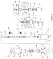
- FIG. 6 is an exploded view that shows the manner in which the various elements may interconnect with each other as previously described in relation to FIGS. 1 to 3 ;
- FIG. 6 also illustrates additional elements not specifically shown in FIGS. 1 to 3 .
- an O-ring 60 which may be adapted to be received in a recess 62 located in the upper portion of the collar 20, more particularly centrally in the bore which is provided for the actuator 115.
- a catch plate 64 may be provided for the catch fingers 50.
- Catch finger pins 66 of which there may be three in number, may be provided to permit pivoting of the fingers 50 in radial slots 74.
- the lower end of the push/pull control cable 190 may be threadedly received in a threaded opening at the upper end of the pointed lock pin 56, while the upper end of the push/pull control cable 190 may be threadedly received in a threaded opening at the bottom of the indicator 28.
- the indicator 28 may be fully enclosed within the indicator housing 22 and an indicator spring 76 may be compressed between the lower end of the indicator 28 and the upper connector housing 194.
- Four button-head screws 78 may pass through suitable holes in the indicator housing 22 and into the sides of the upper connector housing 194.
- buttons-head screws 78 may pass through suitable holes in the lower connector housing 191 and into the sides of the catch plate 64.
- the collar 20 may be provided with a brass tipped set screw 72 which secures the collar 20 onto the upper threaded end of the pipe nipple 12.
- a pipe cap spacer 116 held into a fixed position on the underside of the collar 20 by pipe cap spacer bolts 117.
- FIG. 4 when a pig 88 passes through the pipeline 14 and actuates the trigger 18, the actuator 115 may move upwardly and engage the sides of the three catch fingers 50 causing them to pivot outwardly and release the lock pin 56 and the push pull control cable 190.
- the spring 76 may commence to raise the indicator 28.
- FIG. 5 represents the condition of the pig detector 10 after the pig 88 has passed completely by. In the FIG. 5 position, the spring 76 has raised the indicator 28 to its uppermost position so that it serves as a signal to anyone looking that way that the pig has passed this particular pig detector.
- the spring 48 may move the trigger 18 back to its original position and the garter spring 52 may move the fingers 50 back to their original position. If it is desired to recock the pig detector, all one needs to do is push downwardly on the cap 26 until the lock pin 56 is engaged by the catches 54 at the tops of the catch fingers 50.
- FIGS. 7 and 8 relate to enlarged details of the catch finger assembly.
- FIG. 7 is a sectional view taken along section line 7-7 of FIG. 3 , showing the catch fingers 50 in engagement with the lock pin 56. Note that the fingers 50 may be urged pivotally inwardly towards each other by means of the garter spring 52 which encircles the fingers midway of their ends.
- FIG. 8 is a sectional view taken along section line 8-8 of FIG. 5 after the lock pin 56 has been released. The garter spring 52 has returned the fingers 50 to their original position as shown in FIG. 5 and the actuator 115 is bearing against the lower sides of the fingers.
- FIGS. 7 and 8 also show three triangularly arranged holes or bores 67 which may extend like chords across the catch plate 64 so as to receive therein the catch finger pins 66 which permit the pivoting of the fingers 50 in the radial slots 74.
- FIG. 9 is a transverse sectional view taken along section line 9-9 of FIG. 3 and cuts through the collar 20 roughly in the neighborhood of the set screw 72.
- Housing 38 is shown separated from the pipe 12 by means of an annular space 41 which represents the recess in which the O-ring 40 and 84 may be located.
- FIG. 10 is a sectional view of the bottom end of the trigger 18 showing its attachment to the plunger 120.
- the trigger 18 may be provided with a transverse opening 90 which may be in alignment with a transverse opening 92 in the plunger 120.
- a pin 94 having a set screw 96 at one end thereof may be adapted to pass through the opening 90 in the trigger 18 and also through the hole 92 in the plunger 120 to hold the trigger 18 in place.
Landscapes
- Engineering & Computer Science (AREA)
- General Engineering & Computer Science (AREA)
- Chemical & Material Sciences (AREA)
- Combustion & Propulsion (AREA)
- Mechanical Engineering (AREA)
- Feeding And Watering For Cattle Raising And Animal Husbandry (AREA)
Claims (1)
- Vorrichtung zum Anzeigen des Durchlaufs eines Molchs über einen vorbestimmten Ort in einer Rohrleitung hinaus, wobei die Vorrichtung Folgendes beinhaltet:einen Molchdetektor (10) zum Verbinden einer Rohrleitung und zum Kommunizieren mit dem Inneren der Rohrleitung durch eine Öffnung an dem Ort;einen Auslöser (18), der im Molchdetektor verschiebbar eingebaut ist und dafür ausgelegt ist, durch die Öffnung nach unten in das Innere der Rohrleitung hinein zu ragen;ein Anzeigergehäuse (22), das sich in einem Abstand vom Molchdetektor befindet;einen Anzeiger (28), der im Anzeigergehäuse (22) vertikal verschiebbar eingebaut ist;dadurch gekennzeichnet, dass die Vorrichtung ferner Folgendes beinhaltet:
einen Druck-Zug-Steuerseilzug (190) mit einem ersten, am Auslöser angebrachten Ende und einem zweiten, am Anzeiger angebrachten Ende, so dass der Druck-Zug-Steuerseilzug, wenn sich ein Molch in der Rohrleitung am Auslöser vorbeibewegt und den Auslöser betätigt, den Anzeiger nach oben über das Anzeigergehäuse hinaus bewegen lässt, um optisch anzuzeigen, dass der Molch vorbeigelaufen ist.
Applications Claiming Priority (2)
| Application Number | Priority Date | Filing Date | Title |
|---|---|---|---|
| US202163146142P | 2021-02-05 | 2021-02-05 | |
| US17/540,978 US12338940B2 (en) | 2021-02-05 | 2021-12-02 | Pig detector |
Publications (3)
| Publication Number | Publication Date |
|---|---|
| EP4040032A1 EP4040032A1 (de) | 2022-08-10 |
| EP4040032C0 EP4040032C0 (de) | 2023-06-21 |
| EP4040032B1 true EP4040032B1 (de) | 2023-06-21 |
Family
ID=80122068
Family Applications (1)
| Application Number | Title | Priority Date | Filing Date |
|---|---|---|---|
| EP22275010.1A Active EP4040032B1 (de) | 2021-02-05 | 2022-01-26 | Molchdetektor |
Country Status (3)
| Country | Link |
|---|---|
| US (1) | US12338940B2 (de) |
| EP (1) | EP4040032B1 (de) |
| CA (1) | CA3147576A1 (de) |
Families Citing this family (1)
| Publication number | Priority date | Publication date | Assignee | Title |
|---|---|---|---|---|
| US12600491B2 (en) * | 2023-02-15 | 2026-04-14 | Hamilton Sundstrand Corporation | Push button motion indicator mechanism |
Family Cites Families (13)
| Publication number | Priority date | Publication date | Assignee | Title |
|---|---|---|---|---|
| US3306251A (en) * | 1964-09-16 | 1967-02-28 | Gen Descaling Co Ltd | Pipe line pig or sphere locating devices |
| US3478717A (en) * | 1968-03-04 | 1969-11-18 | Joseph V Kidd | Pressure balanced mechanical detector with permanent magnetic means activating indicator means |
| DE2544075A1 (de) | 1974-10-03 | 1976-04-08 | Helmerich & Payne | Vorrichtung und verfahren zum normieren eines pipelinemolch-detektors |
| US4491018A (en) * | 1983-06-17 | 1985-01-01 | F. H. Maloney Company | Pig detector |
| US4596204A (en) * | 1983-08-15 | 1986-06-24 | T. D. Williamson, Inc. | Flag-type pig-sig |
| US5263220A (en) * | 1991-11-22 | 1993-11-23 | Campbell Doug C | Pig passage indicator mechanism incorporating a fluid seal construction |
| US6857329B2 (en) | 1998-02-18 | 2005-02-22 | Donsa, Inc. | Pig for detecting an obstruction in a pipeline |
| US6357384B1 (en) * | 2000-03-20 | 2002-03-19 | Dwane O. Laymon | Pig detector |
| US6823751B1 (en) * | 2002-05-22 | 2004-11-30 | Meter Engineers, Inc. | Sphere or pig detection switch assembly |
| US7861665B2 (en) * | 2007-05-11 | 2011-01-04 | Tdw Delaware Inc. | Pipeline pig signal with adjustable mounting |
| US8109162B2 (en) | 2009-04-20 | 2012-02-07 | Enduro Pipeline Services | Pig detector |
| JP5438631B2 (ja) | 2010-08-30 | 2014-03-12 | 大工 貞晋 | ピグ通過確認装置 |
| US9248477B2 (en) * | 2012-11-06 | 2016-02-02 | Tdw Delaware, Inc. | Pipeline pig signal trigger cavity seal |
-
2021
- 2021-12-02 US US17/540,978 patent/US12338940B2/en active Active
-
2022
- 2022-01-26 EP EP22275010.1A patent/EP4040032B1/de active Active
- 2022-02-03 CA CA3147576A patent/CA3147576A1/en active Pending
Also Published As
| Publication number | Publication date |
|---|---|
| EP4040032C0 (de) | 2023-06-21 |
| CA3147576A1 (en) | 2022-08-05 |
| US12338940B2 (en) | 2025-06-24 |
| EP4040032A1 (de) | 2022-08-10 |
| US20220252201A1 (en) | 2022-08-11 |
Similar Documents
| Publication | Publication Date | Title |
|---|---|---|
| US4303263A (en) | Instant fitting for reinforced multilayer flexible tubings for fluids | |
| US5988277A (en) | Running tool for static wellhead plug | |
| EP4040032B1 (de) | Molchdetektor | |
| US4306628A (en) | Safety switch for well tools | |
| US5427504A (en) | Gas operated plunger for lifting well fluids | |
| US4134455A (en) | Oilwell tubing tester with trapped valve seal | |
| US9983103B2 (en) | Gas sampling apparatus | |
| US5237136A (en) | Hydrostatic pressure responsive bypass safety switch | |
| CA1062147A (en) | Wireline latching apparatus and method of use | |
| AU615826B2 (en) | Apparatus for monitoring a parameter in a well | |
| US8109162B2 (en) | Pig detector | |
| CA1134741A (en) | Valve apparatus | |
| US4714233A (en) | Adapter bracket for making a valve fire safe | |
| US6357384B1 (en) | Pig detector | |
| FR2650074A3 (fr) | Dispositif de surveillance de pression | |
| US4407361A (en) | Tool trap | |
| US10408702B2 (en) | Hydraulic plate and pipe connection system | |
| US4660596A (en) | Inside B.O.P. valve | |
| US3204992A (en) | Rotary safety joint | |
| US20070029079A1 (en) | Subsea tubing hanger assembly for an oil or gas well | |
| CN209324336U (zh) | 井下工具检测装置 | |
| CN108571318B (zh) | 接箍定位器 | |
| US4314243A (en) | Well pump theft alarm | |
| US12486732B2 (en) | Downhole activated trigger device and associated tools and methods | |
| EP3611389A1 (de) | Lineares stellglied mit verriegelung und verriegelungsanzeige |
Legal Events
| Date | Code | Title | Description |
|---|---|---|---|
| PUAI | Public reference made under article 153(3) epc to a published international application that has entered the european phase |
Free format text: ORIGINAL CODE: 0009012 |
|
| STAA | Information on the status of an ep patent application or granted ep patent |
Free format text: STATUS: REQUEST FOR EXAMINATION WAS MADE |
|
| 17P | Request for examination filed |
Effective date: 20220126 |
|
| AK | Designated contracting states |
Kind code of ref document: A1 Designated state(s): AL AT BE BG CH CY CZ DE DK EE ES FI FR GB GR HR HU IE IS IT LI LT LU LV MC MK MT NL NO PL PT RO RS SE SI SK SM TR |
|
| GRAP | Despatch of communication of intention to grant a patent |
Free format text: ORIGINAL CODE: EPIDOSNIGR1 |
|
| STAA | Information on the status of an ep patent application or granted ep patent |
Free format text: STATUS: GRANT OF PATENT IS INTENDED |
|
| RIC1 | Information provided on ipc code assigned before grant |
Ipc: F16L 55/48 20060101AFI20230118BHEP |
|
| INTG | Intention to grant announced |
Effective date: 20230201 |
|
| GRAS | Grant fee paid |
Free format text: ORIGINAL CODE: EPIDOSNIGR3 |
|
| GRAA | (expected) grant |
Free format text: ORIGINAL CODE: 0009210 |
|
| STAA | Information on the status of an ep patent application or granted ep patent |
Free format text: STATUS: THE PATENT HAS BEEN GRANTED |
|
| AK | Designated contracting states |
Kind code of ref document: B1 Designated state(s): AL AT BE BG CH CY CZ DE DK EE ES FI FR GB GR HR HU IE IS IT LI LT LU LV MC MK MT NL NO PL PT RO RS SE SI SK SM TR |
|
| REG | Reference to a national code |
Ref country code: CH Ref legal event code: EP |
|
| REG | Reference to a national code |
Ref country code: DE Ref legal event code: R096 Ref document number: 602022000143 Country of ref document: DE |
|
| REG | Reference to a national code |
Ref country code: AT Ref legal event code: REF Ref document number: 1581113 Country of ref document: AT Kind code of ref document: T Effective date: 20230715 |
|
| REG | Reference to a national code |
Ref country code: IE Ref legal event code: FG4D |
|
| U01 | Request for unitary effect filed |
Effective date: 20230630 |
|
| U07 | Unitary effect registered |
Designated state(s): AT BE BG DE DK EE FI FR IT LT LU LV MT NL PT SE SI Effective date: 20230710 |
|
| REG | Reference to a national code |
Ref country code: LT Ref legal event code: MG9D |
|
| PG25 | Lapsed in a contracting state [announced via postgrant information from national office to epo] |
Ref country code: NO Free format text: LAPSE BECAUSE OF FAILURE TO SUBMIT A TRANSLATION OF THE DESCRIPTION OR TO PAY THE FEE WITHIN THE PRESCRIBED TIME-LIMIT Effective date: 20230921 |
|
| PG25 | Lapsed in a contracting state [announced via postgrant information from national office to epo] |
Ref country code: RS Free format text: LAPSE BECAUSE OF FAILURE TO SUBMIT A TRANSLATION OF THE DESCRIPTION OR TO PAY THE FEE WITHIN THE PRESCRIBED TIME-LIMIT Effective date: 20230621 Ref country code: HR Free format text: LAPSE BECAUSE OF FAILURE TO SUBMIT A TRANSLATION OF THE DESCRIPTION OR TO PAY THE FEE WITHIN THE PRESCRIBED TIME-LIMIT Effective date: 20230621 Ref country code: GR Free format text: LAPSE BECAUSE OF FAILURE TO SUBMIT A TRANSLATION OF THE DESCRIPTION OR TO PAY THE FEE WITHIN THE PRESCRIBED TIME-LIMIT Effective date: 20230922 |
|
| PG25 | Lapsed in a contracting state [announced via postgrant information from national office to epo] |
Ref country code: SK Free format text: LAPSE BECAUSE OF FAILURE TO SUBMIT A TRANSLATION OF THE DESCRIPTION OR TO PAY THE FEE WITHIN THE PRESCRIBED TIME-LIMIT Effective date: 20230621 |
|
| PG25 | Lapsed in a contracting state [announced via postgrant information from national office to epo] |
Ref country code: ES Free format text: LAPSE BECAUSE OF FAILURE TO SUBMIT A TRANSLATION OF THE DESCRIPTION OR TO PAY THE FEE WITHIN THE PRESCRIBED TIME-LIMIT Effective date: 20230621 |
|
| PG25 | Lapsed in a contracting state [announced via postgrant information from national office to epo] |
Ref country code: IS Free format text: LAPSE BECAUSE OF FAILURE TO SUBMIT A TRANSLATION OF THE DESCRIPTION OR TO PAY THE FEE WITHIN THE PRESCRIBED TIME-LIMIT Effective date: 20231021 |
|
| PG25 | Lapsed in a contracting state [announced via postgrant information from national office to epo] |
Ref country code: SM Free format text: LAPSE BECAUSE OF FAILURE TO SUBMIT A TRANSLATION OF THE DESCRIPTION OR TO PAY THE FEE WITHIN THE PRESCRIBED TIME-LIMIT Effective date: 20230621 Ref country code: SK Free format text: LAPSE BECAUSE OF FAILURE TO SUBMIT A TRANSLATION OF THE DESCRIPTION OR TO PAY THE FEE WITHIN THE PRESCRIBED TIME-LIMIT Effective date: 20230621 Ref country code: RO Free format text: LAPSE BECAUSE OF FAILURE TO SUBMIT A TRANSLATION OF THE DESCRIPTION OR TO PAY THE FEE WITHIN THE PRESCRIBED TIME-LIMIT Effective date: 20230621 Ref country code: IS Free format text: LAPSE BECAUSE OF FAILURE TO SUBMIT A TRANSLATION OF THE DESCRIPTION OR TO PAY THE FEE WITHIN THE PRESCRIBED TIME-LIMIT Effective date: 20231021 Ref country code: ES Free format text: LAPSE BECAUSE OF FAILURE TO SUBMIT A TRANSLATION OF THE DESCRIPTION OR TO PAY THE FEE WITHIN THE PRESCRIBED TIME-LIMIT Effective date: 20230621 Ref country code: CZ Free format text: LAPSE BECAUSE OF FAILURE TO SUBMIT A TRANSLATION OF THE DESCRIPTION OR TO PAY THE FEE WITHIN THE PRESCRIBED TIME-LIMIT Effective date: 20230621 |
|
| U20 | Renewal fee for the european patent with unitary effect paid |
Year of fee payment: 3 Effective date: 20240105 |
|
| PG25 | Lapsed in a contracting state [announced via postgrant information from national office to epo] |
Ref country code: PL Free format text: LAPSE BECAUSE OF FAILURE TO SUBMIT A TRANSLATION OF THE DESCRIPTION OR TO PAY THE FEE WITHIN THE PRESCRIBED TIME-LIMIT Effective date: 20230621 |
|
| REG | Reference to a national code |
Ref country code: DE Ref legal event code: R097 Ref document number: 602022000143 Country of ref document: DE |
|
| PLBE | No opposition filed within time limit |
Free format text: ORIGINAL CODE: 0009261 |
|
| STAA | Information on the status of an ep patent application or granted ep patent |
Free format text: STATUS: NO OPPOSITION FILED WITHIN TIME LIMIT |
|
| 26N | No opposition filed |
Effective date: 20240322 |
|
| PG25 | Lapsed in a contracting state [announced via postgrant information from national office to epo] |
Ref country code: MC Free format text: LAPSE BECAUSE OF FAILURE TO SUBMIT A TRANSLATION OF THE DESCRIPTION OR TO PAY THE FEE WITHIN THE PRESCRIBED TIME-LIMIT Effective date: 20230621 |
|
| PG25 | Lapsed in a contracting state [announced via postgrant information from national office to epo] |
Ref country code: MC Free format text: LAPSE BECAUSE OF FAILURE TO SUBMIT A TRANSLATION OF THE DESCRIPTION OR TO PAY THE FEE WITHIN THE PRESCRIBED TIME-LIMIT Effective date: 20230621 |
|
| PG25 | Lapsed in a contracting state [announced via postgrant information from national office to epo] |
Ref country code: IE Free format text: LAPSE BECAUSE OF NON-PAYMENT OF DUE FEES Effective date: 20240126 |
|
| PG25 | Lapsed in a contracting state [announced via postgrant information from national office to epo] |
Ref country code: IE Free format text: LAPSE BECAUSE OF NON-PAYMENT OF DUE FEES Effective date: 20240126 |
|
| U20 | Renewal fee for the european patent with unitary effect paid |
Year of fee payment: 4 Effective date: 20250121 |
|
| PG25 | Lapsed in a contracting state [announced via postgrant information from national office to epo] |
Ref country code: CY Free format text: LAPSE BECAUSE OF FAILURE TO SUBMIT A TRANSLATION OF THE DESCRIPTION OR TO PAY THE FEE WITHIN THE PRESCRIBED TIME-LIMIT; INVALID AB INITIO Effective date: 20220126 |
|
| REG | Reference to a national code |
Ref country code: CH Ref legal event code: PL |
|
| PG25 | Lapsed in a contracting state [announced via postgrant information from national office to epo] |
Ref country code: CH Free format text: LAPSE BECAUSE OF NON-PAYMENT OF DUE FEES Effective date: 20250131 |
|
| PG25 | Lapsed in a contracting state [announced via postgrant information from national office to epo] |
Ref country code: TR Free format text: LAPSE BECAUSE OF FAILURE TO SUBMIT A TRANSLATION OF THE DESCRIPTION OR TO PAY THE FEE WITHIN THE PRESCRIBED TIME-LIMIT Effective date: 20230621 |
|
| U20 | Renewal fee for the european patent with unitary effect paid |
Year of fee payment: 5 Effective date: 20260120 |
|
| PGFP | Annual fee paid to national office [announced via postgrant information from national office to epo] |
Ref country code: GB Payment date: 20260120 Year of fee payment: 5 |