EP4039979A1 - Gear pump - Google Patents
Gear pump Download PDFInfo
- Publication number
- EP4039979A1 EP4039979A1 EP20871137.4A EP20871137A EP4039979A1 EP 4039979 A1 EP4039979 A1 EP 4039979A1 EP 20871137 A EP20871137 A EP 20871137A EP 4039979 A1 EP4039979 A1 EP 4039979A1
- Authority
- EP
- European Patent Office
- Prior art keywords
- face
- gear
- fluid
- receiver
- communication
- Prior art date
- Legal status (The legal status is an assumption and is not a legal conclusion. Google has not performed a legal analysis and makes no representation as to the accuracy of the status listed.)
- Granted
Links
Images


Classifications
-
- F—MECHANICAL ENGINEERING; LIGHTING; HEATING; WEAPONS; BLASTING
- F04—POSITIVE - DISPLACEMENT MACHINES FOR LIQUIDS; PUMPS FOR LIQUIDS OR ELASTIC FLUIDS
- F04C—ROTARY-PISTON, OR OSCILLATING-PISTON, POSITIVE-DISPLACEMENT MACHINES FOR LIQUIDS; ROTARY-PISTON, OR OSCILLATING-PISTON, POSITIVE-DISPLACEMENT PUMPS
- F04C2/00—Rotary-piston machines or pumps
- F04C2/08—Rotary-piston machines or pumps of intermeshing-engagement type, i.e. with engagement of co-operating members similar to that of toothed gearing
- F04C2/12—Rotary-piston machines or pumps of intermeshing-engagement type, i.e. with engagement of co-operating members similar to that of toothed gearing of other than internal-axis type
- F04C2/14—Rotary-piston machines or pumps of intermeshing-engagement type, i.e. with engagement of co-operating members similar to that of toothed gearing of other than internal-axis type with toothed rotary pistons
- F04C2/18—Rotary-piston machines or pumps of intermeshing-engagement type, i.e. with engagement of co-operating members similar to that of toothed gearing of other than internal-axis type with toothed rotary pistons with similar tooth forms
-
- F—MECHANICAL ENGINEERING; LIGHTING; HEATING; WEAPONS; BLASTING
- F04—POSITIVE - DISPLACEMENT MACHINES FOR LIQUIDS; PUMPS FOR LIQUIDS OR ELASTIC FLUIDS
- F04C—ROTARY-PISTON, OR OSCILLATING-PISTON, POSITIVE-DISPLACEMENT MACHINES FOR LIQUIDS; ROTARY-PISTON, OR OSCILLATING-PISTON, POSITIVE-DISPLACEMENT PUMPS
- F04C15/00—Component parts, details or accessories of machines, pumps or pumping installations, not provided for in groups F04C2/00 - F04C14/00
-
- F—MECHANICAL ENGINEERING; LIGHTING; HEATING; WEAPONS; BLASTING
- F04—POSITIVE - DISPLACEMENT MACHINES FOR LIQUIDS; PUMPS FOR LIQUIDS OR ELASTIC FLUIDS
- F04C—ROTARY-PISTON, OR OSCILLATING-PISTON, POSITIVE-DISPLACEMENT MACHINES FOR LIQUIDS; ROTARY-PISTON, OR OSCILLATING-PISTON, POSITIVE-DISPLACEMENT PUMPS
- F04C15/00—Component parts, details or accessories of machines, pumps or pumping installations, not provided for in groups F04C2/00 - F04C14/00
- F04C15/0042—Systems for the equilibration of forces acting on the machines or pump
-
- F—MECHANICAL ENGINEERING; LIGHTING; HEATING; WEAPONS; BLASTING
- F04—POSITIVE - DISPLACEMENT MACHINES FOR LIQUIDS; PUMPS FOR LIQUIDS OR ELASTIC FLUIDS
- F04C—ROTARY-PISTON, OR OSCILLATING-PISTON, POSITIVE-DISPLACEMENT MACHINES FOR LIQUIDS; ROTARY-PISTON, OR OSCILLATING-PISTON, POSITIVE-DISPLACEMENT PUMPS
- F04C2/00—Rotary-piston machines or pumps
- F04C2/08—Rotary-piston machines or pumps of intermeshing-engagement type, i.e. with engagement of co-operating members similar to that of toothed gearing
- F04C2/082—Details specially related to intermeshing engagement type machines or pumps
- F04C2/088—Elements in the toothed wheels or the carter for relieving the pressure of fluid imprisoned in the zones of engagement
-
- F—MECHANICAL ENGINEERING; LIGHTING; HEATING; WEAPONS; BLASTING
- F04—POSITIVE - DISPLACEMENT MACHINES FOR LIQUIDS; PUMPS FOR LIQUIDS OR ELASTIC FLUIDS
- F04C—ROTARY-PISTON, OR OSCILLATING-PISTON, POSITIVE-DISPLACEMENT MACHINES FOR LIQUIDS; ROTARY-PISTON, OR OSCILLATING-PISTON, POSITIVE-DISPLACEMENT PUMPS
- F04C2240/00—Components
- F04C2240/30—Casings or housings
-
- F—MECHANICAL ENGINEERING; LIGHTING; HEATING; WEAPONS; BLASTING
- F04—POSITIVE - DISPLACEMENT MACHINES FOR LIQUIDS; PUMPS FOR LIQUIDS OR ELASTIC FLUIDS
- F04C—ROTARY-PISTON, OR OSCILLATING-PISTON, POSITIVE-DISPLACEMENT MACHINES FOR LIQUIDS; ROTARY-PISTON, OR OSCILLATING-PISTON, POSITIVE-DISPLACEMENT PUMPS
- F04C2240/00—Components
- F04C2240/50—Bearings
- F04C2240/54—Hydrostatic or hydrodynamic bearing assemblies specially adapted for rotary positive displacement pumps or compressors
-
- F—MECHANICAL ENGINEERING; LIGHTING; HEATING; WEAPONS; BLASTING
- F04—POSITIVE - DISPLACEMENT MACHINES FOR LIQUIDS; PUMPS FOR LIQUIDS OR ELASTIC FLUIDS
- F04C—ROTARY-PISTON, OR OSCILLATING-PISTON, POSITIVE-DISPLACEMENT MACHINES FOR LIQUIDS; ROTARY-PISTON, OR OSCILLATING-PISTON, POSITIVE-DISPLACEMENT PUMPS
- F04C2240/00—Components
- F04C2240/50—Bearings
- F04C2240/56—Bearing bushings or details thereof
-
- F—MECHANICAL ENGINEERING; LIGHTING; HEATING; WEAPONS; BLASTING
- F04—POSITIVE - DISPLACEMENT MACHINES FOR LIQUIDS; PUMPS FOR LIQUIDS OR ELASTIC FLUIDS
- F04C—ROTARY-PISTON, OR OSCILLATING-PISTON, POSITIVE-DISPLACEMENT MACHINES FOR LIQUIDS; ROTARY-PISTON, OR OSCILLATING-PISTON, POSITIVE-DISPLACEMENT PUMPS
- F04C2240/00—Components
- F04C2240/60—Shafts
Definitions
- the disclosure herein relates to a gear pump of a floating bearing type, which uses rotation of gears to pressurize and expel fluid, and in particular to a gear pump that keeps applying proper pressure onto the floating bearings even at higher rotational speed.
- a gear pump is usually provided with a pair of gears mutually in mesh and a housing that houses the gears and, by rotating the pair of gears in a flow path defined by the housing, pressurizes and expels fluid.
- a large flow rate is unhopeful, it is preferably applicable to some uses in which continuous fluid discharge is required. Examples of such uses are manufacturing equipment for extruding high viscosity polymers to produce resin products, hydraulic devices using pressurized working oil, and fuel feeder to reciprocating or jet engines.
- Fixed bearings may be often used for supporting gears in the gear pump but, in considerable cases, floating bearings may be chosen.
- a floating bearing In a gear pump of a floating bearing type, a floating bearing is slightly movable axially and is pressed onto a gear wheel under a proper pressure to prevent fluid leakage through side faces thereof. Any spring of an elastic body may be used for pressurization onto the bearing and yet a pressure of the fluid pressurized by the gear pump by itself may be used.
- the pressure generated by the gear pump in turn generates a reactive force on the gear wheel, which tends to pull the bearing away from the gear wheel.
- the pressurization on the bearing is required to be sufficient to counter this force and otherwise the bearing will float out of the gear wheel and then the fluid will begin to leak, thereby reducing the efficiency of the gear pump.
- the pressurization is excessive, resistance to rotation of the gears will increase. This would also cause reduction of efficiency of the gear pump and as well heat generation by the resistance might give rise to unintentional failure.
- a gear pump for pressurizing and expelling fluid is provided with: a casing including a suction port configured to suck the fluid, and a discharge port configured to expel the pressurized fluid; a gear including a wheel portion rimmed by gear teeth and a shaft portion axially elongated from the wheel portion, the gear being so housed in the casing that the gear teeth, by rotation of the gear about an axis, transport the fluid from the suction port to the discharge port; and a floating bearing rotatably supporting the shaft portion and being movable axially, the floating bearing including a sealing face in contact with the wheel portion, a receiver face axially opposed to the sealing face, the receiver face including a first receiver face in combination with the casing defining a first pressurization chamber in communication with the suction port, a second receiver face in combination with the casing defining a second pressurization chamber in communication with the discharge port, a third receiver face in combination with the casing defining a third pressurization chamber, and
- pressure on the sealing face extracted through the communication path contains a pressure variate of an opposite phase relative to fluctuation of pressurization applied to the bearing and acts as negative feedback to the third receiver face, the pressurization on the bearing is kept within a proper range.
- a gear pump according to the present embodiment is used for fuel supply to an aeronautic engine for example and it pressurizes and expels relatively low viscosity fluid like oil such as kerosene.
- the following description relates to an example which employs a pair of gears mutually in mesh to rotate in inverse directions but it is merely for convenience of explanation. Three or more gears may be used or use of only one gear is possible. Further, one of the gears is connected via a shaft or gearing with an external power source and the other is a follower gear, although any particular references will not be found in the following description. Or, both the gears may be driving gears.
- the gear pump 1 is generally constituted of a pair of gears mutually in mesh and a casing 3 housing them.
- the casing 3 is provided with a suction port 5 and a discharge port 7.
- the former generally sucks fluid FL before pressurization and the latter expels pressurized fluid FH.
- the suction port 5 and the discharge port 7 are opened on both ends of the casing 3 but, as it is not limiting of course, they may be opened on upper and lower faces or side faces.
- the casing 3 is configured to fluid-tightly seal its interior against the exterior, except communication between the interior and the exterior through the suction port 5 and the discharge port 7.
- the casing 3 is further so dimensioned as to contact with the peripheries of the wheel portions 9 and, as the gears make rotary motions R about respective axes, fluid enclosed in between gear teeth around the wheel portions 9 is transported with being pressurized.
- the suction port 5 is opened around the start point thereof and the discharge port 7 is opened around the end point thereof, thereby the fluid is sucked through the suction port 5 and pressurized and expelled through the discharged port 7.
- Each gear is constituted of the wheel portion 9 rimmed by gear teeth and a shaft portion 9S axially elongated from the wheel portion 9.
- the shaft portion 9S serves for a pivot supported by a floating bearing 11 as described later, and the wheel portion 9 has a larger diameter than that and is generally cylindrical.
- the gear teeth is toothed on the periphery of the wheel portion 9 and may be formed as radial teeth toothed in parallel with the axis but instead may be slanted relative to the axis.
- Side faces of the wheel portion 9 may be flat so as to have face contact with sealing faces that will be described later.
- the shaft portion 9S may be formed in a unitary body with the wheel portion 9 but may be a separated body and combined therewith by means of press-fitting or such.
- Each shaft portion 9S is rotatably supported by the bearings 11, 13 so that the gear is rotatable about its axis.
- the bearing 11 is, on one hand, a floating bearing movable axially and the bearing 13 may be, on the other hand, a fixed bearing fixed to, or at least immovable relative to, the casing 3. Or, the other bearing 13 may be a floating bearing also. Both the bearings 11, 13, or at least outer peripheries thereof, have substantially close contact with the casing 3.
- end faces thereof have some gaps toward the casing 3 and in particular the end face of the floating bearing 11 opposed to the faces facing to the wheel portion 9 holds pressurization chambers GL, GM and GH between itself and the casing 3, into which the fluid is introduced to pressurize the floating bearing 11. Details about them will be described later.
- the bearings 11, 13 fit on the peripheries of the shaft portion 9S and rotatably support it, and at one ends thereof have contact with the side faces of the wheel portion 9. Referring to FIG. 3 in combination with FIGs. 1 and 2 , between the internal peripheries of the bearings 11, 13 and the outer periphery of the shaft portion 9S, narrow gaps GS may be held and the fluid FL before pressurization flows into the gaps GS to effect lubrication.
- Each bearing 11, 13 as a whole is generally cylindrical but a portion thereof in contact with the adjacent bearing 11, 13 may be cut out to be flat.
- the bearings 11, 13 at the ends in contact with the side faces of the wheel portion 9 have diameters sufficient to have face contact with substantially whole surfaces of the faces but, at portions fitting on the shaft portions 9S, may have smaller diameters.
- the ends having face contact with the side faces of the wheel portion 9 function as sealing faces for preventing fluid leakage through the side faces. These sealing faces are generally flat but have some recessed structures as described later.
- each floating bearing 11 the end axially opposed to the sealing face is constituted of pressure-receiver faces 11L, 11M, 11H respectively receiving pressurization by the fluid.
- Each floating bearing 11 may, although inessential, have a structure with stepwise diminution in diameter with distance from the wheel portion.
- the endmost or radially innermost shoulder may be the low-pressure receiver face 11L and the proximate or radially outermost shoulder may be the high-pressure receiver face 11H.
- the low-pressure receiver face 11L in combination with the casing 3 defines a chamber GL.
- the chamber GL is directly or indirectly in communication with the suction port 5 and, as the fluid FL before pressurization is introduced therein, functions as a low-pressure pressurization chamber GL for pressurizing the low-pressure receiver face 11L.
- the low-pressure pressurization chamber GL may further be in communication with a gap GS inside the inner periphery of the bearing 11.
- the chamber GH is directly or indirectly in communication with the discharge port 7 and, as the pressurized fluid FH is introduced therein, functions as a high-pressure pressurization chamber GH for pressurizing the high-pressure receiver face 11H.
- Each floating bearing 11 may be further provided with a shoulder radially outside the low-pressure receiver face 11L and radially inside the high-pressure receiver face 11H. This shoulder functions as a mid-pressure receiver face 11M, which in combination with the casing 3 defines a mid-pressure pressurization chamber GM.
- the floating bearing 11 may be further provided with a communication path 15 passing through the bearing of itself and opened on this shoulder and the sealing face. To the mid-pressure receiver face 11M, as described later, a pressure PM on the sealing face is applied through the communication path 15. Functions of the mid-pressure pressurization chamber GM or the mid-pressure receiver face 11M will be described later in more detail.
- O-rings or gaskets may be interposed around the floating bearing 11 for example.
- the stepwise structure described above is beneficial in interposing the O-rings or the gaskets between respective shoulders.
- a part of or the totality of the receiver faces 11L, 11M, 11H may be on an identical plane.
- the sealing face has an opening on the communication path 15, which is located radially inward from the gear teeth and radially outward from the shaft portion 9S.
- the sealing face may, although inessential, have a groove 17 continuous from the opening.
- the groove 17 can reserve a certain amount of fluid therein and is thus helpful to stabilize the pressure of the fluid fed to the communication path 15.
- the sealing face may, although inessential, have a recessed portion 19 in communication with the suction port 5 and a recessed portion 21 in communication with the discharge port 7, both of which function as fluid reservoirs.
- the floating bearing 11 Before starting the rotary motion R of the gears, as the fluid FL before pressurization intrudes in the low-pressure pressurization chamber GL to pressurize the low-pressure receiver face 11L, the floating bearing 11 is lightly pressed onto the wheel portion 9, thereby preventing the fluid from leaking through the side faces of the wheel portion 9.
- a spring of an elastic body may be used to apply pressurization.
- FIG. 4 schematically illustrates this pressure gradient but it is not known whether the pressure gradient is so linear or not as in the drawing.
- the pressurized fluid FH is introduced into the high-pressure pressurization chamber GH and its high pressure PH is there applied to the high-pressure receiver face 11H.
- the pressurization is increased, the force that pulls the floating bearing 11 away from the wheel portion 9 is created, whereas opposed force acts on the high-pressure receiver face 11H. Consequently, in principle, both these forces compete with each other to prevent the fluid leakage through the side faces of the wheel portion 9.
- FIG. 5 another pressure gradient is created in the radial direction on the sealing face. More specifically, as the fluid FL intrudes into the gap GS around the shaft portion 9S, the pressure therein is identical to the low pressure PL, but the pressure rises along the radially outward direction and gets highest at a region 9T where the gear teeth sweep. As the opening of the communication path 15 is positioned radially inward from the wheel portion 9 and radially outward from the shaft portion 9S, the medium pressure PM is extracted, introduced to the pressurization chamber GM, and there applied to the mid-pressure receiver face 11M.
- This pressure gradient is not settled but reflects the degree of contact between the sealing face and the side face of the wheel portion. More specifically, when the pressurization onto the floating bearing 11 is excessively small and then the contact between the sealing face and the side face of the wheel portion becomes insufficient, the pressure on the sealing face may be increased as intrusion of the pressurized fluid FH into the sealing face becomes prominent. On the other hand, when the pressurization gets excessive and then the contact becomes overly tight, the pressure on the sealing face may get lower.
- the medium pressure PM thus contains a pressure variate dP of an opposite phase relative to disturbances in the pressurization on the floating bearing 11.
- the pressure variate dP of an opposite phase relative to the disturbance in the pressurization is applied to the mid-pressure receiver face 11M.
- This functions as a negative feedback circuit of a sort to keep the pressurization on the floating bearing 11 relative to the wheel portion within a proper range.
- the medium pressure PM and the pressure variate dP applied to the mid-pressure receiver face 11M depend on the position of the opening of the communication path 15 on the sealing face and also on the position of the groove 17.
- the positions in the radial direction and in the circumferential direction can be properly selected and then the device can be designed in accordance with the required properties.
- a range applicable thereto may extend from the shaft portion 9S to the gear teeth in the radial direction and from the recess portion 19 to the recess portion 21 in the circumferential direction, as described already.
- a gear pump which uses negative feedback to keep pressurization on bearings within a proper range, thereby retaining stability of the floating bearings even if the rotation speed is increased.
Landscapes
- Engineering & Computer Science (AREA)
- Mechanical Engineering (AREA)
- General Engineering & Computer Science (AREA)
- Rotary Pumps (AREA)
- Details And Applications Of Rotary Liquid Pumps (AREA)
Abstract
Description
- The disclosure herein relates to a gear pump of a floating bearing type, which uses rotation of gears to pressurize and expel fluid, and in particular to a gear pump that keeps applying proper pressure onto the floating bearings even at higher rotational speed.
- A gear pump is usually provided with a pair of gears mutually in mesh and a housing that houses the gears and, by rotating the pair of gears in a flow path defined by the housing, pressurizes and expels fluid. Although a large flow rate is unhopeful, it is preferably applicable to some uses in which continuous fluid discharge is required. Examples of such uses are manufacturing equipment for extruding high viscosity polymers to produce resin products, hydraulic devices using pressurized working oil, and fuel feeder to reciprocating or jet engines.
- Fixed bearings may be often used for supporting gears in the gear pump but, in considerable cases, floating bearings may be chosen. In a gear pump of a floating bearing type, a floating bearing is slightly movable axially and is pressed onto a gear wheel under a proper pressure to prevent fluid leakage through side faces thereof. Any spring of an elastic body may be used for pressurization onto the bearing and yet a pressure of the fluid pressurized by the gear pump by itself may be used.
- The
patent literatures 1 and 2 disclose related arts. -
- PTL 1:
Japanese Patent Application Laid-open No. 2005-344538 - PTL 2: International Publication No.
WO 2017/009994 - The pressure generated by the gear pump in turn generates a reactive force on the gear wheel, which tends to pull the bearing away from the gear wheel. The pressurization on the bearing is required to be sufficient to counter this force and otherwise the bearing will float out of the gear wheel and then the fluid will begin to leak, thereby reducing the efficiency of the gear pump. In contrast if the pressurization is excessive, resistance to rotation of the gears will increase. This would also cause reduction of efficiency of the gear pump and as well heat generation by the resistance might give rise to unintentional failure.
- If the generated pressure is used to apply pressurization onto the bearing, increase in pressure on one face of the bearing leads to increase in pressure on the other face. Thus any proper design made in light of dimensions of areas subject to the pressurization could balance them with each other. The present inventor, however, found out through his study that, when rotational speeds of the gears are increased in order to improve efficiency, the floating bearing could get unstable. The gear pump as disclosed hereafter has been created to overcome this problem.
- A gear pump for pressurizing and expelling fluid according to the present disclosure is provided with: a casing including a suction port configured to suck the fluid, and a discharge port configured to expel the pressurized fluid; a gear including a wheel portion rimmed by gear teeth and a shaft portion axially elongated from the wheel portion, the gear being so housed in the casing that the gear teeth, by rotation of the gear about an axis, transport the fluid from the suction port to the discharge port; and a floating bearing rotatably supporting the shaft portion and being movable axially, the floating bearing including a sealing face in contact with the wheel portion, a receiver face axially opposed to the sealing face, the receiver face including a first receiver face in combination with the casing defining a first pressurization chamber in communication with the suction port, a second receiver face in combination with the casing defining a second pressurization chamber in communication with the discharge port, a third receiver face in combination with the casing defining a third pressurization chamber, and a communication path having an opening on the sealing face and communicating the opening with the third pressurization chamber.
- As pressure on the sealing face extracted through the communication path contains a pressure variate of an opposite phase relative to fluctuation of pressurization applied to the bearing and acts as negative feedback to the third receiver face, the pressurization on the bearing is kept within a proper range.
-
-
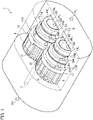
FIG. 1 is a perspective view of a gear pump in accordance with an embodiment, which partially shows its interior. -
FIG. 2 is an elevational sectional view of the gear pump. -
FIG. 3 is a plan view of a sealing face of a bearing viewed from the side of the gear wheel. -
FIG. 4 is a graph schematically depicting a pressure profile of fluid on the sealing face, which is viewed along a direction where the gear wheel rotates. -
FIG. 5 is a graph schematically depicting a pressure profile of fluid on the sealing face, which is viewed along a diameter of the gear wheel. - Exemplary embodiments will be described hereinafter with reference to the appended drawings.
- A gear pump according to the present embodiment is used for fuel supply to an aeronautic engine for example and it pressurizes and expels relatively low viscosity fluid like oil such as kerosene. The following description relates to an example which employs a pair of gears mutually in mesh to rotate in inverse directions but it is merely for convenience of explanation. Three or more gears may be used or use of only one gear is possible. Further, one of the gears is connected via a shaft or gearing with an external power source and the other is a follower gear, although any particular references will not be found in the following description. Or, both the gears may be driving gears.
- Referring mainly to
FIGs. 1 ,2 , thegear pump 1 is generally constituted of a pair of gears mutually in mesh and acasing 3 housing them. - The
casing 3 is provided with asuction port 5 and adischarge port 7. The former generally sucks fluid FL before pressurization and the latter expels pressurized fluid FH. InFIG. 1 , thesuction port 5 and thedischarge port 7 are opened on both ends of thecasing 3 but, as it is not limiting of course, they may be opened on upper and lower faces or side faces. - The
casing 3 is configured to fluid-tightly seal its interior against the exterior, except communication between the interior and the exterior through thesuction port 5 and thedischarge port 7. Thecasing 3 is further so dimensioned as to contact with the peripheries of thewheel portions 9 and, as the gears make rotary motions R about respective axes, fluid enclosed in between gear teeth around thewheel portions 9 is transported with being pressurized. In a path in each revolution of the rotary motion R of thewheel portions 9, thesuction port 5 is opened around the start point thereof and thedischarge port 7 is opened around the end point thereof, thereby the fluid is sucked through thesuction port 5 and pressurized and expelled through the dischargedport 7. - Each gear is constituted of the
wheel portion 9 rimmed by gear teeth and ashaft portion 9S axially elongated from thewheel portion 9. Theshaft portion 9S serves for a pivot supported by a floating bearing 11 as described later, and thewheel portion 9 has a larger diameter than that and is generally cylindrical. The gear teeth is toothed on the periphery of thewheel portion 9 and may be formed as radial teeth toothed in parallel with the axis but instead may be slanted relative to the axis. Side faces of thewheel portion 9 may be flat so as to have face contact with sealing faces that will be described later. Theshaft portion 9S may be formed in a unitary body with thewheel portion 9 but may be a separated body and combined therewith by means of press-fitting or such. - Each
shaft portion 9S is rotatably supported by thebearings bearing 11 is, on one hand, a floating bearing movable axially and thebearing 13 may be, on the other hand, a fixed bearing fixed to, or at least immovable relative to, thecasing 3. Or, the other bearing 13 may be a floating bearing also. Both thebearings casing 3. On the other hand, end faces thereof have some gaps toward thecasing 3 and in particular the end face of the floating bearing 11 opposed to the faces facing to thewheel portion 9 holds pressurization chambers GL, GM and GH between itself and thecasing 3, into which the fluid is introduced to pressurize the floatingbearing 11. Details about them will be described later. - The
bearings shaft portion 9S and rotatably support it, and at one ends thereof have contact with the side faces of thewheel portion 9. Referring toFIG. 3 in combination withFIGs. 1 and2 , between the internal peripheries of thebearings shaft portion 9S, narrow gaps GS may be held and the fluid FL before pressurization flows into the gaps GS to effect lubrication. Each bearing 11, 13 as a whole is generally cylindrical but a portion thereof in contact with the adjacent bearing 11, 13 may be cut out to be flat. - The
bearings wheel portion 9 have diameters sufficient to have face contact with substantially whole surfaces of the faces but, at portions fitting on theshaft portions 9S, may have smaller diameters. The ends having face contact with the side faces of thewheel portion 9 function as sealing faces for preventing fluid leakage through the side faces. These sealing faces are generally flat but have some recessed structures as described later. - Referring again to
FIGs. 1 ,2 , in each floating bearing 11, the end axially opposed to the sealing face is constituted of pressure-receiver faces 11L, 11M, 11H respectively receiving pressurization by the fluid. Each floating bearing 11 may, although inessential, have a structure with stepwise diminution in diameter with distance from the wheel portion. The endmost or radially innermost shoulder may be the low-pressure receiver face 11L and the proximate or radially outermost shoulder may be the high-pressure receiver face 11H. - The low-
pressure receiver face 11L in combination with thecasing 3 defines a chamber GL. The chamber GL is directly or indirectly in communication with thesuction port 5 and, as the fluid FL before pressurization is introduced therein, functions as a low-pressure pressurization chamber GL for pressurizing the low-pressure receiver face 11L. The low-pressure pressurization chamber GL may further be in communication with a gap GS inside the inner periphery of thebearing 11. The high-pressure receiver face 11H in combination with thecasing 3, similarly, defines a chamber GH. The chamber GH is directly or indirectly in communication with thedischarge port 7 and, as the pressurized fluid FH is introduced therein, functions as a high-pressure pressurization chamber GH for pressurizing the high-pressure receiver face 11H. - Each floating
bearing 11 may be further provided with a shoulder radially outside the low-pressure receiver face 11L and radially inside the high-pressure receiver face 11H. This shoulder functions as amid-pressure receiver face 11M, which in combination with thecasing 3 defines a mid-pressure pressurization chamber GM. The floatingbearing 11 may be further provided with acommunication path 15 passing through the bearing of itself and opened on this shoulder and the sealing face. To themid-pressure receiver face 11M, as described later, a pressure PM on the sealing face is applied through thecommunication path 15. Functions of the mid-pressure pressurization chamber GM or themid-pressure receiver face 11M will be described later in more detail. - To separate the pressurization chambers GL, GM, GH from each other, O-rings or gaskets may be interposed around the floating
bearing 11 for example. The stepwise structure described above is beneficial in interposing the O-rings or the gaskets between respective shoulders. Alternatively, by using any other proper structure or separation means, a part of or the totality of the receiver faces 11L, 11M, 11H may be on an identical plane. - Referring again to
FIG. 3 , the sealing face has an opening on thecommunication path 15, which is located radially inward from the gear teeth and radially outward from theshaft portion 9S. The sealing face may, although inessential, have agroove 17 continuous from the opening. Thegroove 17 can reserve a certain amount of fluid therein and is thus helpful to stabilize the pressure of the fluid fed to thecommunication path 15. Further the sealing face may, although inessential, have a recessedportion 19 in communication with thesuction port 5 and a recessedportion 21 in communication with thedischarge port 7, both of which function as fluid reservoirs. - Before starting the rotary motion R of the gears, as the fluid FL before pressurization intrudes in the low-pressure pressurization chamber GL to pressurize the low-
pressure receiver face 11L, the floatingbearing 11 is lightly pressed onto thewheel portion 9, thereby preventing the fluid from leaking through the side faces of thewheel portion 9. In place of, or in addition to, such pressurization, a spring of an elastic body may be used to apply pressurization. - Referring to
FIG. 4 in combination withFIGs. 1-3 , when the rotary motion R about the axis is given to eachwheel portion 9, the fluid is transported in the circumferential direction C and simultaneously pressurized from a low pressure PL given to the fluid FL before pressurization up to a high pressure PH generated in the fluid FH after pressurization.FIG. 4 schematically illustrates this pressure gradient but it is not known whether the pressure gradient is so linear or not as in the drawing. - The pressurized fluid FH is introduced into the high-pressure pressurization chamber GH and its high pressure PH is there applied to the high-
pressure receiver face 11H. As the pressurization is increased, the force that pulls the floatingbearing 11 away from thewheel portion 9 is created, whereas opposed force acts on the high-pressure receiver face 11H. Consequently, in principle, both these forces compete with each other to prevent the fluid leakage through the side faces of thewheel portion 9. - On the other hand, as schematically shown in
FIG. 5 , another pressure gradient is created in the radial direction on the sealing face. More specifically, as the fluid FL intrudes into the gap GS around theshaft portion 9S, the pressure therein is identical to the low pressure PL, but the pressure rises along the radially outward direction and gets highest at aregion 9T where the gear teeth sweep. As the opening of thecommunication path 15 is positioned radially inward from thewheel portion 9 and radially outward from theshaft portion 9S, the medium pressure PM is extracted, introduced to the pressurization chamber GM, and there applied to themid-pressure receiver face 11M. - This pressure gradient is not settled but reflects the degree of contact between the sealing face and the side face of the wheel portion. More specifically, when the pressurization onto the floating
bearing 11 is excessively small and then the contact between the sealing face and the side face of the wheel portion becomes insufficient, the pressure on the sealing face may be increased as intrusion of the pressurized fluid FH into the sealing face becomes prominent. On the other hand, when the pressurization gets excessive and then the contact becomes overly tight, the pressure on the sealing face may get lower. The medium pressure PM thus contains a pressure variate dP of an opposite phase relative to disturbances in the pressurization on the floatingbearing 11. As this medium pressure PM is extracted and introduced to the mid-pressure pressurization chamber GM, the pressure variate dP of an opposite phase relative to the disturbance in the pressurization is applied to themid-pressure receiver face 11M. This functions as a negative feedback circuit of a sort to keep the pressurization on the floatingbearing 11 relative to the wheel portion within a proper range. - As will be understood from the above descriptions, the medium pressure PM and the pressure variate dP applied to the
mid-pressure receiver face 11M depend on the position of the opening of thecommunication path 15 on the sealing face and also on the position of thegroove 17. The positions in the radial direction and in the circumferential direction can be properly selected and then the device can be designed in accordance with the required properties. A range applicable thereto may extend from theshaft portion 9S to the gear teeth in the radial direction and from therecess portion 19 to therecess portion 21 in the circumferential direction, as described already. - Although certain embodiments have been described above, modifications and variations of the embodiments described above will occur to those skilled in the art, in light of the above teachings.
- Provided is a gear pump which uses negative feedback to keep pressurization on bearings within a proper range, thereby retaining stability of the floating bearings even if the rotation speed is increased.
Claims (5)
- A gear pump for pressurizing and expelling fluid, comprising:a casing including a suction port configured to suck the fluid, and a discharge port configured to expel the pressurized fluid;a gear including a wheel portion rimmed by gear teeth and a shaft portion axially elongated from the wheel portion, the gear being so housed in the casing that the gear teeth, by rotation of the gear about an axis, transport the fluid from the suction port to the discharge port; anda floating bearing rotatably supporting the shaft portion and being movable axially, the floating bearing includinga sealing face in contact with the wheel portion,a receiver face axially opposed to the sealing face, the receiver face includinga first receiver face in combination with the casing defining a first pressurization chamber in communication with the suction port,a second receiver face in combination with the casing defining a second pressurization chamber in communication with the discharge port,a third receiver face in combination with the casing defining a third pressurization chamber, anda communication path having an opening on the sealing face and communicating the opening with the third pressurization chamber.
- The gear pump of claim 1, wherein the third receiver face is disposed radially outward from the first receiver face and radially inward from the second receiver face.
- The gear pump of claim 1, wherein the opening of the communication path is disposed radially inward from the gear teeth and radially outward from the shaft portion on the sealing face.
- The gear pump of claim 1, further comprising:
a groove so elongated in a circumferential direction on the sealing face as to keep the fluid between the wheel portion and the sealing face, the groove being in communication with the opening of the communication path. - The gear pump of claim 4, wherein the sealing face has a low-pressure recessed portion in communication with the suction port and a high-pressure recessed portion in communication with the discharge port, and the groove is so disposed as not to overlap with the low-pressure recessed portion and the high-pressure recessed portion in the circumferential direction.
Applications Claiming Priority (2)
| Application Number | Priority Date | Filing Date | Title |
|---|---|---|---|
| JP2019182915 | 2019-10-03 | ||
| PCT/JP2020/035162 WO2021065525A1 (en) | 2019-10-03 | 2020-09-17 | Gear pump |
Publications (3)
| Publication Number | Publication Date |
|---|---|
| EP4039979A1 true EP4039979A1 (en) | 2022-08-10 |
| EP4039979A4 EP4039979A4 (en) | 2023-10-25 |
| EP4039979B1 EP4039979B1 (en) | 2025-12-17 |
Family
ID=75337984
Family Applications (1)
| Application Number | Title | Priority Date | Filing Date |
|---|---|---|---|
| EP20871137.4A Active EP4039979B1 (en) | 2019-10-03 | 2020-09-17 | Gear pump |
Country Status (4)
| Country | Link |
|---|---|
| US (1) | US11852142B2 (en) |
| EP (1) | EP4039979B1 (en) |
| JP (1) | JP7298704B2 (en) |
| WO (1) | WO2021065525A1 (en) |
Families Citing this family (2)
| Publication number | Priority date | Publication date | Assignee | Title |
|---|---|---|---|---|
| US11933295B2 (en) * | 2022-06-06 | 2024-03-19 | General Electric Company | Tapered shafts for fluid pumps |
| US12313071B1 (en) | 2024-06-14 | 2025-05-27 | Hamilton Sundstrand Corporation | Gear pump with suction housing element providing a tight seal between suction and high-pressure chamber to increase pump efficiency and method of providing tight seal |
Family Cites Families (13)
| Publication number | Priority date | Publication date | Assignee | Title |
|---|---|---|---|---|
| GB883356A (en) * | 1959-04-24 | 1961-11-29 | Thompson Ramo Wooldridge Inc | Improvements in or relating to pumps |
| DE1264958B (en) * | 1960-10-08 | 1968-03-28 | Bosch Gmbh Robert | Gear pump or motor |
| US3372646A (en) * | 1967-03-20 | 1968-03-12 | Borg Warner | Contaminant resistant fluid supply system |
| GB1386237A (en) * | 1971-05-18 | 1975-03-05 | Dowty Hydraulic Units Ltd | Rotary positive-displacement hydraulic machines |
| JPS55107092A (en) * | 1979-02-06 | 1980-08-16 | Kayaba Ind Co Ltd | Loading device for gear pump |
| JPS5738685A (en) * | 1980-08-19 | 1982-03-03 | Matsushita Electric Ind Co Ltd | Gear pump |
| JPS6114489A (en) * | 1984-06-29 | 1986-01-22 | Kayaba Ind Co Ltd | Gear pump or motor |
| JPH04101084A (en) * | 1990-08-17 | 1992-04-02 | Kazuo Moro | External gear pump |
| JP4310563B2 (en) * | 1999-12-10 | 2009-08-12 | 株式会社村田製作所 | Heater and terminal structure of heater |
| JP2005344538A (en) | 2004-06-01 | 2005-12-15 | Hitachi Ltd | Gear pump |
| JP6265008B2 (en) * | 2014-03-31 | 2018-01-24 | 株式会社Ihi | Triple gear pump and fluid supply device |
| EP3324048B1 (en) | 2015-07-16 | 2020-02-26 | IHI Corporation | Triple gear pump and fluid supplying device |
| FR3091317A1 (en) * | 2018-12-26 | 2020-07-03 | Poclain Hydraulics Industrie | Hydraulic pump, cover and flange intended to equip such a pump |
-
2020
- 2020-09-17 EP EP20871137.4A patent/EP4039979B1/en active Active
- 2020-09-17 WO PCT/JP2020/035162 patent/WO2021065525A1/en not_active Ceased
- 2020-09-17 JP JP2021550594A patent/JP7298704B2/en active Active
-
2021
- 2021-11-16 US US17/455,079 patent/US11852142B2/en active Active
Also Published As
| Publication number | Publication date |
|---|---|
| JP7298704B2 (en) | 2023-06-27 |
| US20220074408A1 (en) | 2022-03-10 |
| EP4039979B1 (en) | 2025-12-17 |
| EP4039979A4 (en) | 2023-10-25 |
| US11852142B2 (en) | 2023-12-26 |
| WO2021065525A1 (en) | 2021-04-08 |
| JPWO2021065525A1 (en) | 2021-04-08 |
Similar Documents
| Publication | Publication Date | Title |
|---|---|---|
| US8535030B2 (en) | Gerotor hydraulic pump with fluid actuated vanes | |
| US11852142B2 (en) | Gear pump with floating bearing with receiver faces | |
| US9765778B2 (en) | Variable displacement rotary pump and displacement regulation method | |
| EP3120027B1 (en) | Gear pump with end plates or bearings having spiral grooves | |
| US2601003A (en) | Gear pump | |
| US9890782B2 (en) | Fluid pump with radial bearing between inner rotor and rotary shaft and lubrication groove in outer peripheral surface of radial bearing | |
| US9404495B2 (en) | Variable displacement pump with double eccentric ring and displacement regulation method | |
| US9638190B2 (en) | Oil pump | |
| CN203743802U (en) | Oil pump assembly | |
| US11421685B2 (en) | Vane pump with improved seal assembly for control chamber | |
| CN108474380B (en) | Oil-free screw compressor | |
| KR20170044635A (en) | Vacuum Pump with eccentrically driven vane (eccentric pump design) | |
| US7300267B2 (en) | Unit for delivering fuel to an internal combustion engine | |
| CN211852152U (en) | Stretching type variable gear pump | |
| CN104565751A (en) | Double-tooth-difference cycloidal gear pump | |
| US9885356B2 (en) | Variable displacement pump | |
| US3307480A (en) | Automatically reversible gear pump | |
| JP4917921B2 (en) | External gear pump with relief pocket | |
| US2601004A (en) | Gear pump | |
| CN214221484U (en) | Fluid pump | |
| US5252047A (en) | Gear pump with controlled clamping force | |
| JP3820779B2 (en) | Gear pump and fuel supply apparatus using the same | |
| CN109000141A (en) | A kind of rotor-type oil pump can be reduced abrasion | |
| CN103742774B (en) | Variable displacement oil pump with pressure relief groove | |
| KR101251535B1 (en) | Oil pump for vehicle |
Legal Events
| Date | Code | Title | Description |
|---|---|---|---|
| STAA | Information on the status of an ep patent application or granted ep patent |
Free format text: STATUS: THE INTERNATIONAL PUBLICATION HAS BEEN MADE |
|
| PUAI | Public reference made under article 153(3) epc to a published international application that has entered the european phase |
Free format text: ORIGINAL CODE: 0009012 |
|
| STAA | Information on the status of an ep patent application or granted ep patent |
Free format text: STATUS: REQUEST FOR EXAMINATION WAS MADE |
|
| 17P | Request for examination filed |
Effective date: 20220317 |
|
| AK | Designated contracting states |
Kind code of ref document: A1 Designated state(s): AL AT BE BG CH CY CZ DE DK EE ES FI FR GB GR HR HU IE IS IT LI LT LU LV MC MK MT NL NO PL PT RO RS SE SI SK SM TR |
|
| DAV | Request for validation of the european patent (deleted) | ||
| DAX | Request for extension of the european patent (deleted) | ||
| A4 | Supplementary search report drawn up and despatched |
Effective date: 20230922 |
|
| RIC1 | Information provided on ipc code assigned before grant |
Ipc: F04C 15/00 20060101ALI20230918BHEP Ipc: F04C 2/18 20060101AFI20230918BHEP |
|
| GRAP | Despatch of communication of intention to grant a patent |
Free format text: ORIGINAL CODE: EPIDOSNIGR1 |
|
| STAA | Information on the status of an ep patent application or granted ep patent |
Free format text: STATUS: GRANT OF PATENT IS INTENDED |
|
| INTG | Intention to grant announced |
Effective date: 20250808 |
|
| GRAS | Grant fee paid |
Free format text: ORIGINAL CODE: EPIDOSNIGR3 |
|
| GRAA | (expected) grant |
Free format text: ORIGINAL CODE: 0009210 |
|
| STAA | Information on the status of an ep patent application or granted ep patent |
Free format text: STATUS: THE PATENT HAS BEEN GRANTED |
|
| AK | Designated contracting states |
Kind code of ref document: B1 Designated state(s): AL AT BE BG CH CY CZ DE DK EE ES FI FR GB GR HR HU IE IS IT LI LT LU LV MC MK MT NL NO PL PT RO RS SE SI SK SM TR |
|
| REG | Reference to a national code |
Ref country code: CH Ref legal event code: F10 Free format text: ST27 STATUS EVENT CODE: U-0-0-F10-F00 (AS PROVIDED BY THE NATIONAL OFFICE) Effective date: 20251217 Ref country code: GB Ref legal event code: FG4D |
|
| REG | Reference to a national code |
Ref country code: DE Ref legal event code: R096 Ref document number: 602020064178 Country of ref document: DE |
|
| REG | Reference to a national code |
Ref country code: LT Ref legal event code: MG9D |
|
| PG25 | Lapsed in a contracting state [announced via postgrant information from national office to epo] |
Ref country code: NO Free format text: LAPSE BECAUSE OF FAILURE TO SUBMIT A TRANSLATION OF THE DESCRIPTION OR TO PAY THE FEE WITHIN THE PRESCRIBED TIME-LIMIT Effective date: 20260317 |
|
| PG25 | Lapsed in a contracting state [announced via postgrant information from national office to epo] |
Ref country code: FI Free format text: LAPSE BECAUSE OF FAILURE TO SUBMIT A TRANSLATION OF THE DESCRIPTION OR TO PAY THE FEE WITHIN THE PRESCRIBED TIME-LIMIT Effective date: 20251217 Ref country code: HR Free format text: LAPSE BECAUSE OF FAILURE TO SUBMIT A TRANSLATION OF THE DESCRIPTION OR TO PAY THE FEE WITHIN THE PRESCRIBED TIME-LIMIT Effective date: 20251217 |
|
| PG25 | Lapsed in a contracting state [announced via postgrant information from national office to epo] |
Ref country code: RS Free format text: LAPSE BECAUSE OF FAILURE TO SUBMIT A TRANSLATION OF THE DESCRIPTION OR TO PAY THE FEE WITHIN THE PRESCRIBED TIME-LIMIT Effective date: 20260317 |
|
| REG | Reference to a national code |
Ref country code: NL Ref legal event code: MP Effective date: 20251217 |
|
| PG25 | Lapsed in a contracting state [announced via postgrant information from national office to epo] |
Ref country code: LV Free format text: LAPSE BECAUSE OF FAILURE TO SUBMIT A TRANSLATION OF THE DESCRIPTION OR TO PAY THE FEE WITHIN THE PRESCRIBED TIME-LIMIT Effective date: 20251217 |
|
| PG25 | Lapsed in a contracting state [announced via postgrant information from national office to epo] |
Ref country code: BG Free format text: LAPSE BECAUSE OF FAILURE TO SUBMIT A TRANSLATION OF THE DESCRIPTION OR TO PAY THE FEE WITHIN THE PRESCRIBED TIME-LIMIT Effective date: 20251217 |
|
| REG | Reference to a national code |
Ref country code: AT Ref legal event code: MK05 Ref document number: 1868687 Country of ref document: AT Kind code of ref document: T Effective date: 20251217 |
|
| PG25 | Lapsed in a contracting state [announced via postgrant information from national office to epo] |
Ref country code: NL Free format text: LAPSE BECAUSE OF FAILURE TO SUBMIT A TRANSLATION OF THE DESCRIPTION OR TO PAY THE FEE WITHIN THE PRESCRIBED TIME-LIMIT Effective date: 20251217 |
|
| PG25 | Lapsed in a contracting state [announced via postgrant information from national office to epo] |
Ref country code: LT Free format text: LAPSE BECAUSE OF FAILURE TO SUBMIT A TRANSLATION OF THE DESCRIPTION OR TO PAY THE FEE WITHIN THE PRESCRIBED TIME-LIMIT Effective date: 20251217 |
|
| PG25 | Lapsed in a contracting state [announced via postgrant information from national office to epo] |
Ref country code: SM Free format text: LAPSE BECAUSE OF FAILURE TO SUBMIT A TRANSLATION OF THE DESCRIPTION OR TO PAY THE FEE WITHIN THE PRESCRIBED TIME-LIMIT Effective date: 20251217 |
|
| PG25 | Lapsed in a contracting state [announced via postgrant information from national office to epo] |
Ref country code: ES Free format text: LAPSE BECAUSE OF FAILURE TO SUBMIT A TRANSLATION OF THE DESCRIPTION OR TO PAY THE FEE WITHIN THE PRESCRIBED TIME-LIMIT Effective date: 20251217 |
|
| PG25 | Lapsed in a contracting state [announced via postgrant information from national office to epo] |
Ref country code: PL Free format text: LAPSE BECAUSE OF FAILURE TO SUBMIT A TRANSLATION OF THE DESCRIPTION OR TO PAY THE FEE WITHIN THE PRESCRIBED TIME-LIMIT Effective date: 20251217 |
|
| PG25 | Lapsed in a contracting state [announced via postgrant information from national office to epo] |
Ref country code: IT Free format text: LAPSE BECAUSE OF FAILURE TO SUBMIT A TRANSLATION OF THE DESCRIPTION OR TO PAY THE FEE WITHIN THE PRESCRIBED TIME-LIMIT Effective date: 20251217 |
|
| PG25 | Lapsed in a contracting state [announced via postgrant information from national office to epo] |
Ref country code: AT Free format text: LAPSE BECAUSE OF FAILURE TO SUBMIT A TRANSLATION OF THE DESCRIPTION OR TO PAY THE FEE WITHIN THE PRESCRIBED TIME-LIMIT Effective date: 20251217 |
|
| PG25 | Lapsed in a contracting state [announced via postgrant information from national office to epo] |
Ref country code: EE Free format text: LAPSE BECAUSE OF FAILURE TO SUBMIT A TRANSLATION OF THE DESCRIPTION OR TO PAY THE FEE WITHIN THE PRESCRIBED TIME-LIMIT Effective date: 20251217 |
|
| PG25 | Lapsed in a contracting state [announced via postgrant information from national office to epo] |
Ref country code: PT Free format text: LAPSE BECAUSE OF FAILURE TO SUBMIT A TRANSLATION OF THE DESCRIPTION OR TO PAY THE FEE WITHIN THE PRESCRIBED TIME-LIMIT Effective date: 20260417 Ref country code: IS Free format text: LAPSE BECAUSE OF FAILURE TO SUBMIT A TRANSLATION OF THE DESCRIPTION OR TO PAY THE FEE WITHIN THE PRESCRIBED TIME-LIMIT Effective date: 20260417 |
|
| PG25 | Lapsed in a contracting state [announced via postgrant information from national office to epo] |
Ref country code: CZ Free format text: LAPSE BECAUSE OF FAILURE TO SUBMIT A TRANSLATION OF THE DESCRIPTION OR TO PAY THE FEE WITHIN THE PRESCRIBED TIME-LIMIT Effective date: 20251217 |
|
| PG25 | Lapsed in a contracting state [announced via postgrant information from national office to epo] |
Ref country code: SK Free format text: LAPSE BECAUSE OF FAILURE TO SUBMIT A TRANSLATION OF THE DESCRIPTION OR TO PAY THE FEE WITHIN THE PRESCRIBED TIME-LIMIT Effective date: 20251217 |
|
| PG25 | Lapsed in a contracting state [announced via postgrant information from national office to epo] |
Ref country code: SE Free format text: LAPSE BECAUSE OF FAILURE TO SUBMIT A TRANSLATION OF THE DESCRIPTION OR TO PAY THE FEE WITHIN THE PRESCRIBED TIME-LIMIT Effective date: 20251217 |