EP4039953A1 - Gas discharge housing, arrangement of gas discharge housings, exhaust gas turbocharger with a gas discharge housing and use of a gas discharge housing - Google Patents
Gas discharge housing, arrangement of gas discharge housings, exhaust gas turbocharger with a gas discharge housing and use of a gas discharge housing Download PDFInfo
- Publication number
- EP4039953A1 EP4039953A1 EP21156055.2A EP21156055A EP4039953A1 EP 4039953 A1 EP4039953 A1 EP 4039953A1 EP 21156055 A EP21156055 A EP 21156055A EP 4039953 A1 EP4039953 A1 EP 4039953A1
- Authority
- EP
- European Patent Office
- Prior art keywords
- exhaust gas
- gas outlet
- housing
- outlet housing
- flow
- Prior art date
- Legal status (The legal status is an assumption and is not a legal conclusion. Google has not performed a legal analysis and makes no representation as to the accuracy of the status listed.)
- Withdrawn
Links
Images


Classifications
-
- F—MECHANICAL ENGINEERING; LIGHTING; HEATING; WEAPONS; BLASTING
- F01—MACHINES OR ENGINES IN GENERAL; ENGINE PLANTS IN GENERAL; STEAM ENGINES
- F01D—NON-POSITIVE DISPLACEMENT MACHINES OR ENGINES, e.g. STEAM TURBINES
- F01D9/00—Stators
- F01D9/02—Nozzles; Nozzle boxes; Stator blades; Guide conduits, e.g. individual nozzles
- F01D9/026—Scrolls for radial machines or engines
-
- F—MECHANICAL ENGINEERING; LIGHTING; HEATING; WEAPONS; BLASTING
- F01—MACHINES OR ENGINES IN GENERAL; ENGINE PLANTS IN GENERAL; STEAM ENGINES
- F01N—GAS-FLOW SILENCERS OR EXHAUST APPARATUS FOR MACHINES OR ENGINES IN GENERAL; GAS-FLOW SILENCERS OR EXHAUST APPARATUS FOR INTERNAL COMBUSTION ENGINES
- F01N13/00—Exhaust or silencing apparatus characterised by constructional features ; Exhaust or silencing apparatus, or parts thereof, having pertinent characteristics not provided for in, or of interest apart from, groups F01N1/00 - F01N5/00, F01N9/00, F01N11/00
- F01N13/08—Other arrangements or adaptations of exhaust conduits
- F01N13/10—Other arrangements or adaptations of exhaust conduits of exhaust manifolds
- F01N13/107—More than one exhaust manifold or exhaust collector
-
- F—MECHANICAL ENGINEERING; LIGHTING; HEATING; WEAPONS; BLASTING
- F02—COMBUSTION ENGINES; HOT-GAS OR COMBUSTION-PRODUCT ENGINE PLANTS
- F02B—INTERNAL-COMBUSTION PISTON ENGINES; COMBUSTION ENGINES IN GENERAL
- F02B37/00—Engines characterised by provision of pumps driven at least for part of the time by exhaust
-
- F—MECHANICAL ENGINEERING; LIGHTING; HEATING; WEAPONS; BLASTING
- F05—INDEXING SCHEMES RELATING TO ENGINES OR PUMPS IN VARIOUS SUBCLASSES OF CLASSES F01-F04
- F05D—INDEXING SCHEME FOR ASPECTS RELATING TO NON-POSITIVE-DISPLACEMENT MACHINES OR ENGINES, GAS-TURBINES OR JET-PROPULSION PLANTS
- F05D2220/00—Application
- F05D2220/40—Application in turbochargers
-
- Y—GENERAL TAGGING OF NEW TECHNOLOGICAL DEVELOPMENTS; GENERAL TAGGING OF CROSS-SECTIONAL TECHNOLOGIES SPANNING OVER SEVERAL SECTIONS OF THE IPC; TECHNICAL SUBJECTS COVERED BY FORMER USPC CROSS-REFERENCE ART COLLECTIONS [XRACs] AND DIGESTS
- Y02—TECHNOLOGIES OR APPLICATIONS FOR MITIGATION OR ADAPTATION AGAINST CLIMATE CHANGE
- Y02T—CLIMATE CHANGE MITIGATION TECHNOLOGIES RELATED TO TRANSPORTATION
- Y02T10/00—Road transport of goods or passengers
- Y02T10/10—Internal combustion engine [ICE] based vehicles
- Y02T10/12—Improving ICE efficiencies
Definitions
- the invention is in the field of exhaust gas turbochargers for supercharged internal combustion engines and relates in particular to a gas outlet housing for an exhaust gas turbocharger, the gas outlet housing including a diffuser housing section and a junction housing section. Furthermore, the invention relates to an arrangement with a first gas outlet housing and a second gas outlet housing, an exhaust gas turbocharger with a gas outlet housing, and the use of a gas outlet housing in an exhaust system of internal combustion engines.
- the exhaust gas flow of an internal combustion engine is used to drive a turbine on the exhaust gas side.
- the work generated in this way is used to drive a compressor on the intake side of the combustion engine, which compresses the intake air of the engine.
- the power and efficiency of the internal combustion engine can be increased by charging the internal combustion engine in this way.
- the exhaust gas flow After flowing through the turbine on the exhaust gas side, the exhaust gas flow enters a gas outlet housing of the turbocharger and is discharged from there.
- the exhaust gas flow is advantageously introduced into a diffuser, where the exhaust gas flow is decelerated and the gas pressure of the exhaust gas flow increases in the process. From the WO2019076980A1 It is known that by using a suitable diffuser, the occurrence of detachments or vortices can be avoided.
- a gas outlet housing for an exhaust gas turbocharger.
- the gas outlet housing includes a diffuser housing section for arrangement directly downstream of a turbine of the exhaust gas turbocharger to delay a first exhaust gas stream flowing from the turbine of the exhaust gas turbocharger in an inflow direction directly into the diffuser housing section.
- the diffuser housing section widens in the direction of flow.
- the diffuser housing section protrudes at least partially into the junction housing section.
- the gas exit housing further includes a merger housing section immediately downstream of the diffuser housing section for receiving the delayed first exhaust gas flow from the diffuser housing section and for combining the delayed first exhaust gas flow with a second exhaust gas flow.
- the junction housing portion extends in a second direction substantially transverse to the inflow direction and has two openings opposite in the second direction.
- a first of the two opposed openings is configured to receive the second flow of exhaust gas and a second of the two opposed openings is configured to discharge the second flow of exhaust gas combined with the delayed first flow of exhaust gas.
- a first gas outlet housing and a second gas outlet housing are described.
- the second gas outlet housing is a gas outlet housing according to an embodiment described herein.
- An exhaust gas flow is discharged from an opening in the first gas outlet housing.
- the opening of the first gas outlet housing is fluidly connected to the opening for receiving the second exhaust stream of the second gas outlet housing, so that the exhaust stream discharged from the first gas outlet housing is introduced into the second gas outlet housing as the second exhaust stream.
- the second gas outlet housing is set up to combine the second exhaust gas stream originating from the first gas outlet housing with a first exhaust gas stream flowing into the second gas outlet housing.
- an exhaust gas turbocharger for an internal combustion engine comprising a gas outlet housing according to an embodiment described herein.
- the exhaust gas turbocharger is fluidically connected to the gas outlet housing for introducing the first exhaust gas flow into the diffuser housing section of the gas outlet housing.
- the first exhaust gas flow is an exhaust gas flow originating from the turbine of the exhaust gas turbocharger.
- the invention relates to the use of a gas outlet housing according to an embodiment described herein in an exhaust system of one or more internal combustion engines with exhaust gas turbochargers.
- the use includes the introduction of a first exhaust gas flow emerging from the turbine of the exhaust gas turbocharger in an inflow direction into the diffuser housing section of the gas outlet housing.
- the diffuser housing section of the gas outlet housing decelerates the first exhaust gas flow along the direction of flow.
- the use also includes introducing a second exhaust gas stream into one of the openings of the combining housing section of the gas outlet housing, and introducing the first exhaust gas stream delayed by the diffuser housing section into the combining housing section of the gas outlet housing.
- the combining housing section and/or the diffuser housing section of the gas outlet housing deflects the first exhaust gas flow along the second direction.
- the merger body section immediately follows the diffuser body section.
- the advantage of a gas outlet housing, an arrangement with a first gas outlet housing and a second gas outlet housing, an exhaust gas turbocharger with a gas outlet housing, and the use of a gas outlet housing in an exhaust system of internal combustion engines according to one of the embodiments described herein is that a first exhaust gas stream originating from an exhaust gas turbocharger with a second exhaust stream can be combined in an advantageous manner.
- the combination can take place in such a way that a favorable flow of the combined exhaust gas stream is achieved.
- the first exhaust gas flow is delayed before the combination in a diffuser housing section of the gas outlet housing, so that according to the present invention a separate component can be dispensed with for this purpose. This allows a space-saving design of the exhaust system.
- the gas outlet housing according to the invention is part of the exhaust gas turbocharger and differs in this respect, for example, from a common exhaust gas line (e.g. a common chimney) arranged further downstream for collecting the exhaust gas streams from several exhaust gas turbochargers.
- a common exhaust line does not represent a gas outlet housing according to the invention, since it does not belong to the exhaust gas turbocharger and also has no downstream connection housing section immediately following a diffuser housing section.
- FIG 1 shows schematically a gas outlet housing 100 for an exhaust gas turbocharger 102 according to an embodiment.
- the exhaust gas turbocharger 102 can be fluidically connected to the gas outlet housing 100 in such a way that the entire exhaust gas flow of the exhaust gas turbocharger 102 flows into the gas outlet housing 100 .
- the gas outlet housing 100 can be part of an exhaust gas turbocharger 102 .
- the exhaust gas turbocharger 102 can be an axial exhaust gas turbocharger, in which the first exhaust gas stream flows axially through or around the exhaust gas side turbine 103 .
- the gas outlet housing 100 is a component associated with the exhaust gas turbocharger and can be provided in one piece with other components of the exhaust gas turbocharger (eg cast together with them) or separately from the other components of the exhaust gas turbocharger.
- the gas outlet housing 100 can be completely or partially enclosed by the exhaust gas turbocharger 102 or by housing parts belonging to the exhaust gas turbocharger 102 .
- the gas outlet casing 100 can adjoin the turbocharger 102 .
- the exhaust gas turbocharger 102 is shown as a component that completely spans the gas outlet housing 100 .
- the gas outlet housing itself can also consist of one piece or of several housing parts.
- the gas outlet housing includes a diffuser housing section 110 for delaying a first exhaust gas flow 150 originating from the turbine 103 of the exhaust gas turbocharger 102.
- the diffuser housing section 110 is arranged directly—that is, in particular without an intermediate piece that does not widen—downstream of the turbine 103 of the exhaust gas turbocharger 102 ( in this case, part of the diffuser housing section 110 can even overlap with the turbine 103) and receives the first exhaust gas flow 150 directly from the turbine 103 of the exhaust gas turbocharger 102.
- the first exhaust gas flow 150 flows via an inflow opening 310 into the diffuser housing section 110 of the gas outlet housing 100 a.
- the first exhaust stream 150 has an inflow direction 151 when flowing in.
- the first exhaust gas stream 150 largely maintains the inflow direction 151 , so that the flow direction of the first exhaust gas stream 150 in the diffuser housing section 110 essentially corresponds to the inflow direction 151 . Minor changes in direction, in particular regional changes in direction of parts of the first exhaust gas flow 150 within the diffuser partial housing 110, do not have to be taken into account here.
- the diffuser housing portion 110 widens in the direction of flow.
- the diffuser housing section 110 can widen continuously in the direction of flow of the first exhaust gas flow 150 .
- Such a diffuser housing section can be referred to as an axial diffuser housing section or an axial diffuser.
- the flow cross section available to the first exhaust gas flow 150 can increase as a result of the widening of the diffuser housing section 110 .
- the flow cross section available to the first exhaust gas flow 150 can increase in the flow direction of the first exhaust gas flow 150 .
- Widening can be understood to mean that the diffuser partial housing has a cross section that widens in the direction of flow of the axially flowing first exhaust gas stream.
- the increase in the flow cross section in the direction of flow can lead to a delay in the first exhaust gas flow 150 .
- the increase in the flow cross section in the direction of flow can lead to an increase in the pressure of the first exhaust gas flow 150 .
- the first exhaust gas stream 150 can be decelerated in the diffuser housing section 110 of the gas outlet housing 100 so that the first exhaust gas stream 150 is delayed and/or present with increased pressure when it flows out of the diffuser housing section 110 .
- a first exhaust flow 150 upon exiting the diffuser housing portion 110 may be a delayed first exhaust flow.
- the diffuser housing section 110 is immediately followed in the direction of flow by a combination housing section 120.
- the combination housing section 120 receives the delayed first exhaust gas flow from the diffuser housing section 110.
- the delayed first exhaust gas flow is combined with a second exhaust gas flow 152 united.
- the junction housing section 120 extends in a second direction 153.
- “extend” is to be understood as meaning that the second junction housing section 120 has a spatial extension, for example a length, along the second direction 153 Has.
- the length can be defined, for example, by the line connecting the centers of the opposite openings 130,132.
- the second direction 153 runs essentially transversely to the inflow direction 151, that is to say orthogonally to the inflow direction with a predetermined tolerance, for example with a tolerance of ⁇ 30°.
- the second direction 153 can have an angle of 90° in relation to the inflow direction 151, but the angle can also be in a range of 80°-100°, or in a range of 70°-110° or 60°-120° .
- the junction housing portion 120 may have an interior space that expands or extends along the second direction.
- the combining housing section 120 can be set up to guide an exhaust gas flow, in particular a second exhaust gas flow 152 along the second direction 153 .
- the combining housing section 120 comprises two opposite openings 130, 132 in the second direction 153.
- a first opening 130 can be, as in FIG figure 1 shown to be an opening for receiving a second exhaust gas stream 152, for example an inflow opening for the second exhaust gas stream 152.
- a second opening 132 can be, as in FIG figure 1 shown to be an opening for discharging a second exhaust gas flow 152, for example an outflow opening, in particular a second exhaust gas flow 152 combined with a first exhaust gas flow 150.
- the gas outlet housing 100 can, as in FIG figure 1 shown, be designed so that no preferred flow direction of the second exhaust gas stream 152 is provided.
- the first opening 130 can be an outflow opening and the second opening 132 can be an inflow opening.
- a reversal of the flow direction of the second exhaust gas stream 152 can be provided for the gas outlet housing 100 during operation.
- the delayed first exhaust gas stream 150 flows predominantly in a flow direction that essentially corresponds to the inflow direction 151 (approximately with a tolerance of ⁇ 30°, in embodiments even of ⁇ 15°).
- the second flow of exhaust gas 152 flows from the first opening 130 toward the second opening 132 along the second direction 153.
- the delayed first exhaust gas flow 150 when the delayed first exhaust gas flow 150 combines with the second exhaust gas flow 152 flowing transversely to the delayed first exhaust gas flow 150, the delayed first exhaust gas flow is deflected. The deflection occurs at the same time as the retarded first exhaust gas flow 150 is combined with the second exhaust gas flow 152 at the transition from the diffuser housing section 110 to the combining housing section 120.
- the combined second exhaust gas flow 152 comprises the volumetric flow of the first exhaust gas flow 150 and the second exhaust gas flow 152 at the time receiving the second flow of exhaust gas 152 in the first opening 130.
- the combined second flow of exhaust gas flows along the second direction 153.
- the diffuser housing section 110 can protrude into the combining housing section 120 .
- Protruding is to be understood as meaning that the diffuser housing section is at least partially surrounded by the combining housing section. It is possible to protrude completely, so that the diffuser housing section of the gas outlet housing can only be seen through an inflow opening when the gas outlet housing is viewed from the outside.
- the at least partial protrusion of the diffuser housing section into the junction housing section can enable a compact design of the gas outlet housing and have a favorable influence on the flow of the first and/or the second exhaust gas stream.
- FIG 2 shows a gas outlet housing 100 for an exhaust gas turbocharger 102 according to one embodiment.
- gas outlet housing it can be a gas outlet housing 100 according to a reference to figure 1 act described embodiment.
- the gas outlet housing described is characterized by a predominantly tubular design of the junction housing section 120 , the second direction 153 corresponding to the longitudinal direction of the predominantly tubular junction housing section 120 .
- Gas outlet casing include one or more flanges 240, 242.
- Flanges 240,242 may be provided at openings 130,132.
- a flange can be provided at further openings of the gas outlet housing 100, for example the inflow opening of the diffuser housing section 110 for the first exhaust gas flow 150.
- the flanges can be provided for connection to or for the connection of further components of an exhaust system.
- the other components can be coupled directly to the gas outlet casing using the flange.
- the flanges can be provided for connection to other components, such as other flanges, for example with the aid of bolts, clamps or clamping bands.
- V-band flanges or T-flanges can be provided.
- the flange can be provided for the attachment of at least partially flexible connectors, such as compensators.
- compensators such as compensators
- a gas outlet housing for example in connection with figure 2
- Gas outlet housing 100 described, as well as, for example, also later in connection with figure 4 described gas outlet housing 400 include one or more angled flanges, such as angled flange 242b.
- the flange can comprise a widening, for example an annular one.
- the direction of a flange can be understood as the direction of the surface normal of the flange, with the surface of the flange being understood as the plane defined by the flange (e.g. the bearing surface defined by the flange for a to be connected to the flange further line flange, for example the ring-shaped widening).
- a flange can be understood as angled if it is not attached transversely, ie not at an angle of approximately 90°, to the inflow direction 151 .
- the flange can also be understood as angled when the second direction 153 changes in the junction housing section such that the second direction does not correspond to a straight line.
- the change in the second direction can, as in figure 2 shown, done in sections.
- the change in the second direction can be continuous, for example when the combining housing section is designed in an arc-like manner.
- the angled flange 242b can be designed in such a way that in a partial area of the combining housing section 120 the direction of flow of the second exhaust gas stream 152 and/or the second direction 153b is changed or deflected, for example, by adjusting the shape of the merging housing portion 120.
- the angled flange 242b which typically radially spans the second direction 153 in the area of the flange in one plane, can be angled at an angle of 135° on a plane formed by the inflow direction 151 and the second direction 153 with respect to the inflow direction, for example. like it in figure 2 is shown with angle 250.
- Angled flanges with an angle 250 can be made in a wide range, for example with an angle lying in a range of 40°-140° with respect to the inflow direction 151, such as 60°-120° or 80°-100 °.
- An angled opening 132 is also typically associated with the angled flange 242b.
- gas outlet housing can result from an angled flange.
- the gas outlet housing can be connected to other components, for example other components of an exhaust system, in a favorable manner. Due to the presence of an angled flange, the gas outlet housing can be designed to be compact and space-saving. Due to the presence of an angled flange, the second exhaust gas stream can be guided in a favorable manner, so that unfavorable flows and the associated higher flow resistances, for example due to separation or turbulence, are avoided.
- the diffuser housing section 110 can be designed such that the direction of the first exhaust gas flow 150 is essentially maintained in the area of the diffuser housing section 110 .
- the effect of the diffuser housing section 110 as a diffuser is based on the fact that the cross section of the flow space expands in the radial direction in the inflow direction 151 .
- the diffuser housing section 110 can expand continuously in the direction of flow of the first exhaust gas flow 150 .
- the diffuser housing section 110 can be designed as a conical diffuser.
- the diffuser housing section 110 may include an area through which the first exhaust gas stream does not flow, such as the dead space lying in the center of the diffuser housing section 110 . In the case of larger flow cross sections, the dead space may be necessary in order to prevent centrally located parts of the first exhaust gas stream 150 from flowing through the diffuser housing section 110 without delay.
- first exhaust gas flow 150 is combined with second exhaust gas flow 152, which flows transversely to first exhaust gas flow 150 along second direction 153.
- FIG figure 3 shows a gas outlet housing 100 for an exhaust gas turbocharger according to one embodiment.
- the gas outlet housing shown can be a gas outlet housing 100 according to one of the previously described embodiments. In particular, it can be a plan view of an inflow opening of the diffuser housing section 110 of a gas outlet housing 100 according to FIG figure 2 gas outlet housing 100 described act.
- the diffuser housing section 110 comprises a circular inflow opening 310, which is delimited on the outside by a flange.
- the flange can be used to fluidly connect the gas outlet housing 100 to an exhaust gas turbocharger, so that a first exhaust gas stream originating from the exhaust gas turbocharger flows into the diffuser housing section 110 of the gas outlet housing 100 .
- the circular inflow opening 310 also includes an inner, circular, closed area. This can be an interface, for example a wall, in connection with figure 2 act described dead space.
- the deflection of the first exhaust gas stream 150 which essentially maintains the inflow direction 151 when flowing through the diffuser housing section 110, takes place in the combining housing section 120.
- the deflection typically takes place in the direction of the second direction 153.
- the deflection primarily by combining the first exhaust flow 150 with the second exhaust flow 152 . This assumes that there is a second exhaust flow 152 flowing along the second direction 153 .
- a fluidically advantageous deflection of the first exhaust gas flow 150 can presuppose that the volume flow of the second exhaust gas flow 152 is approximately the same as or higher than the first exhaust gas flow 150 .
- the gas outlet housing 100 it may also be possible that no second exhaust gas flow 152 is present and the first exhaust gas flow 150 is nevertheless deflected after leaving the diffuser housing section 110 in the combining housing section 120 according to an anticipated operating mode.
- this can be achieved in that the gas outlet housing is integrated into an exhaust system in which the inflow of the first exhaust gas stream leads to a back pressure in the exhaust system.
- the exhaust system can be designed such that the back pressure causes the exhaust flow in the junction housing section to escape only through an opening 130,132.
- a component that prevents the exhaust gas flow from freely exiting that opening for example a stationary exhaust gas turbocharger or a pipe with a blind flange
- FIG 4 shows schematically a gas outlet housing 400 for an exhaust gas turbocharger 102 according to an embodiment. Many of the features described in connection with the gas outlet housing 100 can be transferred to the gas outlet housing 400 and are therefore not described again.
- the gas outlet housing 400 comprises a diffuser housing section 110 in which the direction of flow of the first exhaust gas flow 150 changes as it flows through the diffuser housing section and the first exhaust gas flow 150 is thus deflected.
- the first exhaust gas stream 150 can flow into the diffuser housing section 110 in an inflow direction 151 . While flowing through the diffuser housing section 110, the first exhaust gas flow 150 is simultaneously decelerated and deflected in the embodiment shown.
- the delayed first exhaust stream 150 is introduced into the combiner housing section 120 via an introduction port 434 .
- the direction of flow of the delayed first exhaust gas stream 150 when introduced via the introduction opening 434 can essentially correspond to the direction of flow of the second exhaust gas stream 152 which flows along the second direction 153 .
- the flow direction of the delayed first exhaust gas flow 150 can also only partially correspond to the second direction 153, so that in the merger housing section 120 a further deflection of parts of the first exhaust gas stream 150 takes place.
- the deflection can take place, comparable to the gas outlet housing 100 according to a previously described embodiment, during the combination of the first exhaust gas flow 150 with the second exhaust gas flow 152 .
- the combining housing section 120 of the gas outlet housing 400 can comprise two flow spaces.
- the first flow space 422 can be a flow space in which only a second exhaust gas flow 150 flows, as it previously flowed in through the opening 130 .
- the second flow space may 424 be a flow space in which the second exhaust flow 152 is combined with the delayed first exhaust flow 150 to form a combined second exhaust flow 152 .
- the transition area 426 from the first flow space 422 to the second flow space 424 can be described by the initial outflow of a delayed first exhaust gas flow 150 along the second direction 153 from an introduction opening 434 into the combining housing section 120 .
- the transition region 426 can be described as the region where the second exhaust stream 152 is first combined with the delayed first exhaust stream 150 .
- gas outlet housing 400 unlike embodiments of gas outlet housing 100, has a preferred direction for the second exhaust gas flow and thus second direction 153. Since the first exhaust gas flow is already at least partially deflected in the direction of opening 132 in diffuser housing section 110, it is the gas outlet housing 400 provided that the first opening 130 is an inflow opening for a second exhaust gas flow 152, and that the second opening 132 is an outflow opening for the combined second exhaust gas flow 152.
- the at least partial deflection of the first exhaust gas flow 150 in the diffuser housing section 110 can result in the delayed first exhaust gas flow 150 and the second exhaust gas flow 152 already flowing at least partially in the same direction at the point in time when they combine.
- the flow resistance of the housing can advantageously be reduced.
- the formation of detachments or vortices can be at least partially prevented, whereby a favorable flow behavior of the combined second exhaust gas flow can be achieved.
- the cross section of the junction housing portion 120 may expand along the second direction 153 .
- the cross section is to be understood as widened if the cross section of the opening 130 used as the inflow opening is lower than the cross section of the opening 132 used as the outflow opening.
- a section-wise narrowing of the flow space of the combining housing section can be provided in some embodiments and is not to be construed as contradicting the widening of the cross section of the junction housing portion 120 .
- the widening of the cross section of the combining housing section 120 can be carried out in such a way that the flow rate of the second exhaust gas flow 152 when it flows in through the opening 130 is approximately the flow rate of the delayed first Exhaust stream 150 combined second exhaust stream 152 when flowing out through the opening 132 corresponds.
- a favorable flow behavior of the combined second exhaust gas stream can be achieved.
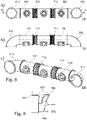
- FIG 5 shows a gas outlet housing 400 for an exhaust gas turbocharger 102 according to an embodiment.
- gas outlet housing it can be a gas outlet housing 400 according to a reference to figure 4 act described embodiment.
- the gas outlet housing 400 can have a diffuser housing section 110 with an at least partially spiral-like collecting section 510 extending in the circumferential direction of the diffuser housing section 110 .
- the circumferential direction can be the direction that radially spans the inflow direction 151 .
- the circumferential direction can be the direction that is normal to the inflow direction 151 .
- the collection portion may be a generally ring-like structure at least partially including a spiral-like portion.
- the spiral-like area can spiral-like radially to the inflow direction expand.
- the spiral-like area can be spiral-like in the axial section, for example the inflow direction 151 .
- the collecting section can fulfill the function of a diffuser.
- the area of the collecting section that is not part of the spiral-like area can include an introduction opening 434 .
- the area of the collection section that is not part of the spiral-like area can differ from the spiral-like collection section 510 by the presence of the introduction opening 434 .
- the spiral shape of the spiral collecting portion 510 is shown in figure 5 in the section plane formed by directions 151 and 153.
- the collecting section directs the first exhaust gas flow 150 radially to delay it. Subsequently, the spiral-like collecting section continues the first exhaust gas flow 150 in the circumferential direction of the diffuser housing section 110 until the first exhaust gas flow 150 can exit via the introduction opening 434 into the combining housing section 120 .
- FIG figure 6 shows a gas outlet housing 400 for an exhaust gas turbocharger according to an embodiment.
- the gas outlet housing shown can be a gas outlet housing 400 according to one of the previously described embodiments. In particular, it can be a plan view of an inflow opening of the diffuser housing section 110 of a gas outlet housing 400 according to FIG figure 5 gas outlet housing 400 described act.
- features located inside the gas outlet housing 400 have also been drawn, in particular features of the diffuser housing section 110.
- the delay in the first exhaust gas flow 150 occurs primarily as a result of the redirection of the first exhaust gas flow in a radial direction.
- the first exhaust gas flow is thus delayed independently of the second exhaust gas flow.
- the result of the diversion in a radial direction is that the cross section available to the first exhaust gas flow 150 increases along the direction of flow as the radius increases. Due to the diversion in the radial direction, the delayed first exhaust gas flow only partially flows in the desired direction 153.
- the diffuser housing section 110 in the in figure 6 shown embodiment only there an introduction opening 434, where the direction of the delayed first exhaust gas flow 150 already corresponds approximately to the second direction.
- the section of the diffuser housing section 110 in which the direction of the delayed first exhaust gas flow 150 contains a vector component pointing opposite to the direction 153 is designed as a spiral-like collecting section 510 .
- the first exhaust gas flow 150 flowing in there is decelerated and, in addition to the radial direction, is further deflected along the circumferential direction of the diffuser housing section 110 .
- the delayed first exhaust gas flow therefore no longer has a directional component flowing counter to the second exhaust gas flow 152 .
- the introduction opening 434 of the diffuser housing section has an opening angle of 180°.
- opening angles of 160°, 150° or 140° can be provided. Further narrowed opening angles of 90°-140° or less than 90° can also be provided.
- figure 7 shows an arrangement 700 of three gas outlet housings, the two outer gas outlet housings being gas outlet housings 100, 400a, 400b according to the embodiments described herein.
- the exhaust gas turbocharger 102 and the turbine 103 are not shown for the sake of clarity.
- One of the external gas outlet housings should be referred to as the second gas outlet housing.
- the inner, central gas outlet housing can be another gas outlet housing according to an embodiment not claimed and is referred to as the first gas outlet housing.
- An arrangement 700 according to figure 7 can be provided to several parallel first exhaust gas streams, such as from several side by side Arranged, for example, come along a line of turbochargers lined up to supply an exhaust system.
- the parallel first exhaust gas streams can flow along the inflow direction 151a and/or 151b.
- the respective gas outlet housings can be connected to one another, for example between a first and a second gas outlet housing or between two second gas outlet housings, by directly connecting the flanges 240 , 242 .
- a second gas outlet housing 100, 400a, 400b which may be a gas outlet housing according to an embodiment described herein, may comprise one or more compensators 710, 712.
- the first compensator 710 is located between a turbine of an exhaust gas turbocharger and the diffuser housing section 110 of the second gas outlet housing and fluidly connects the gas flow emerging from the turbine of the exhaust gas turbocharger to the diffuser housing section 110.
- the first compensator 710 can have a flow from the turbine of the exhaust gas turbocharger Initiate originating first exhaust gas stream 150 in the second gas outlet housing.
- the second compensator 712 is located between an opening 130, 132 of the first gas outlet housing and a discharge opening of the first gas outlet housing.
- the second compensator 712 can introduce a second exhaust gas stream 152 originating from the first gas outlet housing into an opening 130, 132 of the gas outlet housing.
- the compensator 710, 712 can be connected to the gas outlet housing at a flange 240, 242 provided for this purpose.
- the compensators 710, 712 can be partially flexible components that are suitable for guiding hot exhaust gases.
- the compensators can be set up to carry exhaust gases with an overpressure of up to 5 bar compared to the outside.
- the compensator can be in the form of a bellows mounted between two flanges.
- the bellows can be made of folded stainless steel sheet.
- the flanges of the compensator can be set up to be connected to flanges provided on the gas outlet casings.
- the compensator can be an axial compensator.
- the compensator can be set up to compensate for axial and lateral or radial movements.
- the compensator can be set up to avoid stresses occurring between the respective components, for example between an exhaust gas turbocharger and a gas outlet housing, as a result of thermal expansion.
- the compensator can be set up, a transfer of To avoid vibrations between the respective components.
- the compensator can partially protrude into the gas outlet housing.
- the second gas outlet housing to be fluidically connected to a first gas outlet housing.
- a second exhaust gas stream 152 originates from the first gas outlet housing.
- the second exhaust gas stream 152 is introduced into an opening 130, 132 of the second gas outlet housing.
- the second exhaust gas flow can flow in the respective gas outlet housing 100, 400a, 400b along a second direction 753a, 753b.
- the second direction 753a, 753b can be a second direction 153 in relation to the second gas outlet housing.
- a first exhaust gas stream 150 comes from an exhaust gas turbocharger 102.
- the first exhaust gas stream 150 can be introduced into the second gas outlet housing.
- the first exhaust gas flow 150 can be introduced into a diffuser housing section of the second gas outlet housing.
- the first exhaust gas flow 150 and the second exhaust gas flow 152 are combined in the second gas outlet housing to form a combined second exhaust gas flow.
- the embodiment shown shows an exemplary arrangement of a central first gas outlet housing and two second gas outlet housings arranged peripherally thereto.
- the first gas outlet housing is also a gas outlet housing 100, 400 according to the embodiments described herein.
- every second gas outlet housing 100, 400 of the arrangement can then be set up to be fluidically connected to a further gas outlet housing 100, 400, so that a combined second exhaust gas stream of a gas outlet housing of the arrangement flowing out of an opening 132 flows into an opening 130 of a further gas outlet housing of the arrangement is initiated.
- each gas outlet housing receives a second exhaust gas flow via an opening 130, combined with the delayed first exhaust gas flow and forwarded to the following housing (if present) as a combined second exhaust gas flow.
- An exhaust system for example in the form of a chimney, can be arranged for receiving the combined second exhaust gas flow.
- figure 8 shows an arrangement 700 of three gas outlet housings, the two outer gas outlet housings being gas outlet housings 100 according to embodiments described herein.
- the representations a, b, c of figure 8 each correspond to different perspectives of the same arrangement.
- At the in figure 8 shown arrangement can be an embodiment according to in connection with figure 7 act described arrangement 700.
- an advantageous arrangement of the second compensators 712 becomes clear, in which the combined second exhaust gas streams are routed between the respective gas outlet housings without a disadvantageous reduction in the line cross section.
- the arrangement is already largely tubular, which makes clear the advantageous property of the distributor section immediately following the diffuser housing section or of the diffuser housing section lying partially inside the combining housing section in relation to the reduced space requirement.
- additional discharge lines 810, 812 can be provided.
- the derivatives 810, 812 can, as in figure 8 shown cause a deflection of the exhaust gas stream flowing therein. Assuming that a comparable first exhaust gas flow flows into each gas outlet housing of the arrangement 700, if the exhaust gas systems following the discharge lines 810, 812 have comparable properties, the arrangement 700 can achieve an even division of the three first exhaust gas flows into two combined second exhaust gas flows will.
- the arrangement 700 shown can also be a gas outlet housing 100 according to the invention for the central, internal gas outlet housing.
- FIG. 12 shows a schematic sectional view along the inflow direction through part of a diffuser housing section 910 of a gas outlet housing according to FIG one embodiment.
- the diffuser housing section 910 can be an embodiment of a diffuser housing section 110, for example a gas outlet housing 100, for example according to one of the figure 1 , 2 , 3 , 7 or 8th embodiments shown.
- the embodiment shown of the diffuser housing section 110 can be provided for an arrangement of gas outlet housings 700 .
- the diffuser housing section 910 is characterized by being designed as an axial diffuser.
- the diffuser housing section 910 receives a first exhaust gas flow in a flow space 950 on the underside and guides it further along the inflow direction 151 .
- the flow space 950 widens continuously outwards, as a result of which the diffuser housing section 910 acts as a diffuser.
- the diffuser housing portion 910 includes walls 970, with inner and outer walls provided along the entire length of the flow space. In this case, the outer wall serves in part as a delimitation 960 from the flow space of a combining housing section.
- the flow space 950 there is an inner partition between the inner wall and the outer wall, which separates the flow space 950 into an inner and an outer flow space.
- the partition ensures that the opening angle of the diffuser housing section does not exceed a value of 7.5°.
- the in figure 7 and 8th shown gas outlet housing 100, 400 each comprise an exhaust gas turbocharger 102.
- the exhaust gas turbocharger 102 can be fluidically connected to the respective gas outlet housing.
- the gas outlet housing 100, 400 can be part of the exhaust gas turbocharger 102, so that the exhaust gas turbocharger 102 includes the gas outlet housing.
- the first exhaust-gas flow can be an exhaust-gas flow originating from the turbine, in particular the exhaust-gas-side turbine of the exhaust-gas turbocharger 102 .
- the exhaust gas turbocharger can be an axial exhaust gas turbocharger.
- the present invention includes the use of a gas outlet housing 100, 400 according to an embodiment described herein in an exhaust system of one or more internal combustion engines with exhaust gas turbochargers.
- the Use requires the presence of a first exhaust stream 150 and a second exhaust stream 152 .
- the first exhaust flow 150 is typically an exhaust flow originating from a turbine of an exhaust gas turbocharger 102 .
- the second exhaust flow 152 may be an already delayed exhaust flow.
- the second exhaust flow may be an exhaust flow from another turbocharger that has passed through a diffuser and has been decelerated in the process.
- the use includes introducing the first exhaust gas flow 150 in an inflow direction 151 into the diffuser housing section 110 of the gas outlet housing 100, 400.
- the diffuser housing section 110 can be a diffuser housing section according to one of the embodiments described herein.
- the diffuser housing section can be an axial diffuser.
- the diffuser housing section can have an at least partially spiral-like collecting section which extends in the circumferential direction of the diffuser housing section.
- the first exhaust gas flow 150 is decelerated along the flow direction 151 of the first exhaust gas flow.
- the use can provide that the diffuser housing section additionally at least partially deflects or diverts the first exhaust gas flow, for example in the direction of the second exhaust gas flow.
- the use also includes introducing the second exhaust gas stream 152 into one of the openings 130, 132 of the combining housing section 120 of the gas outlet housing 100, 400.
- the second exhaust gas stream can initially flow in a first flow chamber 422 and subsequently into a second Flow space 424 flow.
- the use also includes introducing the first exhaust gas flow 150 delayed by the diffuser housing section into the combining housing section 120.
- the delayed first exhaust gas flow can be introduced into the combining housing section 120 via an introduction opening 434.
- Merger body section 120 immediately follows diffuser body section 110.
- merge body section 120 may follow diffuser body section 110 without a non-flaring interface, and/or diffuser body section 110 may nest within merge body section 120 protrude.
- the diffuser housing section 110 can optionally have a Compensator be coupled to the union housing portion 120. Introducing the delayed first exhaust stream 150 into the merge housing section, the delayed first exhaust stream 150 is merged with the second exhaust stream 152 .
- the combination typically results in the delayed first exhaust gas flow 150, if it does not flow in the second direction, being deflected in the direction of the second direction 153, so that the combined second exhaust gas flow 152 subsequently flows along the second direction 153.
- the use may include exiting the combined second exhaust stream 152 from the gas exit housing.
- the combined second exhaust gas stream 152 can be discharged via one of the openings 130, 132, for example into an exhaust gas system following the gas outlet housing.
- the invention comprises a method for combining the exhaust gas streams exiting from the turbines of two or more exhaust gas turbochargers, comprising for each of the two or more exhaust gas streams: introducing the exhaust gas stream in an inflow direction into a diffuser housing section of a gas outlet housing, with a for each exhaust gas stream Gas outlet housing is provided, so that the number of gas outlet housings corresponds to the number of exhaust gas flows, and wherein the diffuser housing section of the gas outlet housing decelerates the exhaust gas flow along a flow direction; Introducing the exhaust gas flow delayed by the diffuser housing section into a distributor partial housing of the gas outlet housing, the distributor partial housing or the diffuser partial housing of the gas outlet housing deflecting the exhaust gas flow along a direction running transversely to the inflow direction, and the combining housing section directly onto the diffuser -housing section follows; the method further comprising: combining the deflected exhaust gas streams in a common flow space, the common flow space being formed at least in sections by the distributor partial housings of the gas
- the invention includes an arrangement for discharging exhaust gas streams exiting from a respective turbine of two or more exhaust gas turbochargers, the arrangement comprising: two or more gas outlet housings according to an embodiment described herein, with one gas outlet housing of the two or more gas outlet housings being provided on each exhaust gas turbocharger is, so that the exhaust gas stream originating from the turbine of the respective exhaust gas turbocharger flows into the diffuser housing section of the gas outlet housing, and wherein at least one opening of a combining housing section of a first gas outlet housing is connected to an opening, which is adjacent in the outflow direction, of a combining housing section of a second gas outlet housing, so that the delayed exhaust gas streams are combined in a common flow space, the common flow space comprising the respective combining housing section of the two or more gas outlet housings.
- exhaust gas systems of this type can be implemented in a space-saving manner and, compared to conventional exhaust gas systems, have a lower flow resistance and thus a high level of efficiency.
- An exhaust gas system with gas outlet housings according to an embodiment described herein can be implemented with few components, so that an advantage can result from lower material, construction and maintenance costs.
Abstract
Es wird ein Gasaustrittsgehäuse (100, 400) für einen Abgasturbolader (102) beschrieben. Das Gasaustrittsgehäuse (100, 400) umfasst einen Diffusor-Gehäuseabschnitt (110) zur Verzögerung eines aus einer Turbine (103) des Abgasturboladers (102) in einer Einströmrichtung (151) in den Diffusor-Gehäuseabschnitt (110) einströmenden ersten Abgasstroms. Der Diffusor-Gehäuseabschnitt (110) weitet sich in Strömungsrichtung auf. Das Gasaustrittsgehäuse (100, 400) umfasst weiterhin einen stromabwärts unmittelbar auf den Diffusor-Gehäuseabschnitt (110) folgenden Vereinigungs-Gehäuseabschnitt (120) zum Empfangen des verzögerten ersten Abgasstroms aus dem Diffusor-Gehäuseabschnitt (110) und zum Vereinigen des verzögerten ersten Abgasstroms mit einem zweiten Abgasstrom (152). Der Vereinigungs-Gehäuseabschnitt (120) erstreckt sich in einer im Wesentlichen quer zur Einströmrichtung verlaufenden zweiten Richtung und hat zwei in der zweiten Richtung gegenüberliegende Öffnungen (130, 132). Eine erste (130) der zwei gegenüberliegenden Öffnungen ist zum Aufnehmen des zweiten Abgasstroms (152) eingerichtet, und eine zweite (132) der zwei gegenüberliegenden Öffnungen ist zum Ausleiten des mit dem verzögerten ersten Abgasstrom vereinigten zweiten Abgasstroms (152) eingerichtet.A gas outlet housing (100, 400) for an exhaust gas turbocharger (102) is described. The gas outlet housing (100, 400) comprises a diffuser housing section (110) for decelerating a first exhaust gas stream flowing from a turbine (103) of the exhaust gas turbocharger (102) in an inflow direction (151) into the diffuser housing section (110). The diffuser housing section (110) widens in the direction of flow. The gas outlet housing (100, 400) further comprises a combination housing section (120) immediately downstream of the diffuser housing section (110) for receiving the delayed first exhaust gas flow from the diffuser housing section (110) and for combining the delayed first exhaust gas flow with a second exhaust stream (152). The junction housing portion (120) extends in a second direction substantially transverse to the inflow direction and has two openings (130, 132) opposite in the second direction. A first (130) of the two opposed openings is configured to receive the second exhaust flow (152) and a second (132) of the two opposed openings is configured to discharge the second exhaust flow (152) combined with the delayed first exhaust flow.
Description
Die Erfindung liegt auf dem Gebiet der Abgasturbolader für aufgeladene Brennkraftmaschinen und betrifft insbesondere ein Gasaustrittsgehäuse für einen Abgasturbolader, wobei das Gasaustrittsgehäuse einen Diffusor-Gehäuseabschnitt sowie einen Vereinigungs-Gehäuseabschnitt beinhaltet. Des Weiteren betrifft die Erfindung eine Anordnung mit einem ersten Gasaustrittsgehäuse und einem zweiten Gasaustrittsgehäuse, einen Abgasturbolader mit einem Gasaustrittsgehäuse, sowie die Verwendung eines Gasaustrittsgehäuses in einem Abgassystem von Verbrennungsmotoren.The invention is in the field of exhaust gas turbochargers for supercharged internal combustion engines and relates in particular to a gas outlet housing for an exhaust gas turbocharger, the gas outlet housing including a diffuser housing section and a junction housing section. Furthermore, the invention relates to an arrangement with a first gas outlet housing and a second gas outlet housing, an exhaust gas turbocharger with a gas outlet housing, and the use of a gas outlet housing in an exhaust system of internal combustion engines.
In Abgasturboladern wird der Abgasstrom eines Verbrennungsmotors zum Antrieb einer abgasseitigen Turbine verwendet. Die so erzeugte Arbeit wird zum Antrieb eines eingangsseitig am Verbrennungsmotors liegenden Verdichters genutzt, der die Ansaugluft des Motors verdichtet. Durch die so ermöglichte Aufladung des Verbrennungsmotors können die Leistung und der Wirkungsgrad des Verbrennungsmotors gesteigert werden.In exhaust gas turbochargers, the exhaust gas flow of an internal combustion engine is used to drive a turbine on the exhaust gas side. The work generated in this way is used to drive a compressor on the intake side of the combustion engine, which compresses the intake air of the engine. The power and efficiency of the internal combustion engine can be increased by charging the internal combustion engine in this way.
Nach dem Durchströmen der abgasseitigen Turbine gelangt der Abgasstrom in ein Gasaustrittsgehäuse des Turboladers und wird dort abgeleitet. Hierin wird der Abgasstrom zum Erreichen eines möglichst hohen Turbinenwirkungsgrads vorteilhafterweise in einen Diffusor eingeführt, wo der Abgasstrom verzögert wird und sich dabei der Gasdruck des Abgasstroms erhöht. Aus der
Wenn mehrere Abgasströme aus mehreren Abgasturboladern vorliegen, können diese etwa in eine gemeinsame Abgasleitung, wie z.B. einen gemeinsamen Schornstein, geleitet werden. Insbesondere für eine Anordnung, in der eine ungerade Anzahl an Abgasströmen vereinigt werden soll, ist jedoch bislang keine Vorrichtung bekannt, die die Abgasströme auf strömungstechnisch günstige Weise verzögert und vereinigt und gleichzeitig platzsparend und mit einer möglichst geringen Anzahl von verschiedenen Bauteilen realisierbar ist.If there are several exhaust gas streams from several exhaust gas turbochargers, these can be routed into a common exhaust line, such as a common chimney. In particular for an arrangement in which an odd number of exhaust gas streams is to be combined, no device is known to date that decelerates and combines the exhaust gas streams in a fluidically favorable manner and at the same time can be realized in a space-saving manner and with the smallest possible number of different components.
Vor diesem Hintergrund werden daher Vorrichtungen und eine Verwendung gemäß den unabhängigen Ansprüchen der vorliegenden Patenanmeldung vorgeschlagen. Weitere günstige Ausführungsformen ergeben sich aus den abhängigen Ansprüchen und der Beschreibung.Against this background, devices and a use according to the independent claims of the present patent application are therefore proposed. Further favorable embodiments emerge from the dependent claims and the description.
Gemäß einem Aspekt der Erfindung wird ein Gasaustrittsgehäuse für einen Abgasturbolader beschrieben. Das Gasaustrittsgehäuse umfasst einen Diffusor-Gehäuseabschnitt zur Anordnung unmittelbar stromabwärts einer Turbine des Abgasturboladers zur Verzögerung eines aus der Turbine des Abgasturboladers in einer Einströmrichtung unmittelbar in den Diffusor-Gehäuseabschnitt einströmenden ersten Abgasstroms. Der Diffusor-Gehäuseabschnitt weitet sich in Strömungsrichtung auf. Der Diffusor-Gehäuseabschnitt ragt zumindest teilweise in den Vereinigungs-Gehäuseabschnitt hinein. Das Gasaustrittsgehäuse umfasst weiterhin einen stromabwärts unmittelbar auf den Diffusor-Gehäuseabschnitt folgenden Vereinigungs-Gehäuseabschnitt zum Empfangen des verzögerten ersten Abgasstroms aus dem Diffusor-Gehäuseabschnitt und zum Vereinigen des verzögerten ersten Abgasstroms mit einem zweiten Abgasstrom. Der Vereinigungs-Gehäuseabschnitt erstreckt sich in einer im Wesentlichen quer zur Einströmrichtung verlaufenden zweiten Richtung und hat zwei in der zweiten Richtung gegenüberliegende Öffnungen. Eine erste der zwei gegenüberliegenden Öffnungen ist zum Aufnehmen des zweiten Abgasstroms eingerichtet, und eine zweite der zwei gegenüberliegenden Öffnungen ist zum Ausleiten des mit dem verzögerten ersten Abgasstrom vereinigten zweiten Abgasstroms eingerichtet.According to one aspect of the invention, a gas outlet housing for an exhaust gas turbocharger is described. The gas outlet housing includes a diffuser housing section for arrangement directly downstream of a turbine of the exhaust gas turbocharger to delay a first exhaust gas stream flowing from the turbine of the exhaust gas turbocharger in an inflow direction directly into the diffuser housing section. The diffuser housing section widens in the direction of flow. The diffuser housing section protrudes at least partially into the junction housing section. The gas exit housing further includes a merger housing section immediately downstream of the diffuser housing section for receiving the delayed first exhaust gas flow from the diffuser housing section and for combining the delayed first exhaust gas flow with a second exhaust gas flow. The junction housing portion extends in a second direction substantially transverse to the inflow direction and has two openings opposite in the second direction. A first of the two opposed openings is configured to receive the second flow of exhaust gas and a second of the two opposed openings is configured to discharge the second flow of exhaust gas combined with the delayed first flow of exhaust gas.
Gemäß einem Aspekt der Erfindung werden ein erstes Gasaustrittsgehäuse und ein zweites Gasaustrittsgehäuse beschrieben. Das zweite Gasaustrittsgehäuse ist ein Gasaustrittsgehäuse nach einer hierin beschriebenen Ausführungsform. Aus einer Öffnung des ersten Gasaustrittsgehäuses wird ein Abgasstrom ausgeleitet. Die Öffnung des ersten Gasaustrittsgehäuses ist fluidisch mit der Öffnung zum Aufnehmen des zweiten Abgasstroms des zweiten Gasaustrittsgehäuses verbunden, sodass der aus dem ersten Gasaustrittsgehäuse ausgeleitete Abgasstrom als zweiter Abgasstrom in das zweite Gasaustrittsgehäuse eingeleitet wird. Das zweite Gasaustrittsgehäuse ist dazu eingerichtet, den aus dem ersten Gasaustrittsgehäuse stammenden zweiten Abgasstrom mit einem in das zweite Gasaustrittsgehäuse einströmenden ersten Abgasstrom zu vereinigen.According to one aspect of the invention, a first gas outlet housing and a second gas outlet housing are described. The second gas outlet housing is a gas outlet housing according to an embodiment described herein. An exhaust gas flow is discharged from an opening in the first gas outlet housing. The opening of the first gas outlet housing is fluidly connected to the opening for receiving the second exhaust stream of the second gas outlet housing, so that the exhaust stream discharged from the first gas outlet housing is introduced into the second gas outlet housing as the second exhaust stream. The second gas outlet housing is set up to combine the second exhaust gas stream originating from the first gas outlet housing with a first exhaust gas stream flowing into the second gas outlet housing.
Gemäß einem Aspekt der Erfindung wird ein Abgasturbolader für einen Verbrennungsmotor beschrieben. Der Abgasturbolader umfassend ein Gasaustrittsgehäuse gemäß einer hierin beschriebenen Ausführungsform. Der Abgasturbolader ist mit dem Gasaustrittsgehäuse zum Einleiten des ersten Abgasstroms in den Diffusor-Gehäuseabschnitt des Gasaustrittsgehäuses fluidisch verbunden. Der erste Abgasstrom ist ein aus der Turbine des Abgasturboladers stammender Abgasstrom.According to one aspect of the invention, an exhaust gas turbocharger for an internal combustion engine is described. The exhaust gas turbocharger comprising a gas outlet housing according to an embodiment described herein. The exhaust gas turbocharger is fluidically connected to the gas outlet housing for introducing the first exhaust gas flow into the diffuser housing section of the gas outlet housing. The first exhaust gas flow is an exhaust gas flow originating from the turbine of the exhaust gas turbocharger.
Gemäß einem Aspekt betrifft die Erfindung die Verwendung eines Gasaustrittsgehäuses nach einer hierin beschriebenen Ausführungsform in einem Abgassystem eines oder mehrerer Verbrennungsmotoren mit Abgasturboladern. Die Verwendung umfasst das Einleiten eines aus der Turbine des Abgasturboladers austretenden ersten Abgasstroms in einer Einströmrichtung in den Diffusor-Gehäuseabschnitt des Gasaustrittsgehäuses. Der Diffusor-Gehäuseabschnitt des Gasaustrittsgehäuses verzögert den ersten Abgasstrom entlang der Strömungsrichtung. Die Verwendung umfasst weiterhin das Einleiten eines zweiten Abgasstroms in eine der Öffnungen des Vereinigungs-Gehäuseabschnitts des Gasaustrittsgehäuses, sowie das Einleiten des durch den Diffusor-Gehäuseabschnitt verzögerten ersten Abgasstroms in den Vereinigungs-Gehäuseabschnitt des Gasaustrittsgehäuses. Der Vereinigungs-Gehäuseabschnitt und/oder der Diffusor-Gehäuseabschnitt des Gasaustrittsgehäuses lenkt den ersten Abgasstrom entlang der zweiten Richtung um. Der Vereinigungs-Gehäuseabschnitt folgt unmittelbar auf den Diffusor-Gehäuseabschnitt.According to one aspect, the invention relates to the use of a gas outlet housing according to an embodiment described herein in an exhaust system of one or more internal combustion engines with exhaust gas turbochargers. The use includes the introduction of a first exhaust gas flow emerging from the turbine of the exhaust gas turbocharger in an inflow direction into the diffuser housing section of the gas outlet housing. The diffuser housing section of the gas outlet housing decelerates the first exhaust gas flow along the direction of flow. The use also includes introducing a second exhaust gas stream into one of the openings of the combining housing section of the gas outlet housing, and introducing the first exhaust gas stream delayed by the diffuser housing section into the combining housing section of the gas outlet housing. The combining housing section and/or the diffuser housing section of the gas outlet housing deflects the first exhaust gas flow along the second direction. The merger body section immediately follows the diffuser body section.
Der Vorteil eines Gasaustrittsgehäuses, einer Anordnung mit einem ersten Gasaustrittsgehäuse und einem zweiten Gasaustrittsgehäuse, einen Abgasturbolader mit einem Gasaustrittsgehäuse, sowie die Verwendung eines Gasaustrittsgehäuses in einem Abgassystem von Verbrennungsmotoren gemäß einer der hierin beschriebenen Ausführungsformen liegt darin, dass ein erster aus einem Abgasturbolader stammender Abgasstrom mit einem zweiten Abgasstrom auf vorteilhafte Weise vereinigt werden kann. Insbesondere kann die Vereinigung so erfolgen, dass eine günstige Strömung des vereinigten Abgasstroms erreicht wird. Vorteilhafterweise wird der erste Abgasstrom vor der Vereinigung in einem Diffusor-Gehäuseabschnitt des Gasaustrittsgehäuses verzögert, sodass gemäß der vorliegenden Erfindung hierfür auf ein getrenntes Bauteil verzichtet werden kann. Dadurch kann eine platzsparende Ausführung des Abgassystems ermöglicht werden.The advantage of a gas outlet housing, an arrangement with a first gas outlet housing and a second gas outlet housing, an exhaust gas turbocharger with a gas outlet housing, and the use of a gas outlet housing in an exhaust system of internal combustion engines according to one of the embodiments described herein is that a first exhaust gas stream originating from an exhaust gas turbocharger with a second exhaust stream can be combined in an advantageous manner. In particular, the combination can take place in such a way that a favorable flow of the combined exhaust gas stream is achieved. Advantageously, the first exhaust gas flow is delayed before the combination in a diffuser housing section of the gas outlet housing, so that according to the present invention a separate component can be dispensed with for this purpose. This allows a space-saving design of the exhaust system.
Das erfindungsgemäße Gasaustrittsgehäuse ist zum Abgasturbolader gehörig und unterscheidet sich darin z.B. von einer weiter stromabwärts angeordneten gemeinsamen Abgasleitung (z.B. einen gemeinsamen Schornstein) zum Sammeln der Abgasströme aus mehreren Abgasturboladern. Eine solche gemeinsame Abgasleitung stellt kein erfindungsgemäßes Gasaustrittsgehäuse dar, da sie nicht zum Abgasturbolader gehört und außerdem keinen stromabwärts unmittelbar auf einen Diffusor-Gehäuseabschnitt folgenden Vereinigungs-Gehäuseabschnitt aufweist.The gas outlet housing according to the invention is part of the exhaust gas turbocharger and differs in this respect, for example, from a common exhaust gas line (e.g. a common chimney) arranged further downstream for collecting the exhaust gas streams from several exhaust gas turbochargers. Such a common exhaust line does not represent a gas outlet housing according to the invention, since it does not belong to the exhaust gas turbocharger and also has no downstream connection housing section immediately following a diffuser housing section.
Im Weiteren soll die Erfindung anhand von in Figuren dargestellten Ausführungsbeispielen erläutert werden, aus denen sich weitere Vorteile und Abwandlungen ergeben. Dazu zeigen:
-
Figur 1 eine schematische Schnittansicht entlang der Einströmrichtung und der zweiten Richtung durch ein Gasaustrittsgehäuse gemäß einer hierin beschriebenen Ausführungsform -
Figur 2 eine schematische Schnittansicht entlang der Einströmrichtung und der zweiten Richtung durch ein Gasaustrittsgehäuse gemäß einer hierin beschriebenen Ausführungsform -
Figur 3 eine schematische Draufsicht von Seiten der Einström-Öffnung auf ein Gasaustrittsgehäuse gemäß einer hierin beschriebenen Ausführungsform -
Figur 4 eine schematische Schnittansicht entlang der Einströmrichtung und der zweiten Richtung durch ein Gasaustrittsgehäuse gemäß einer hierin beschriebenen Ausführungsform -
Figur 5 eine schematische Schnittansicht entlang der Einströmrichtung und der zweiten Richtung durch ein Gasaustrittsgehäuse gemäß einer hierin beschriebenen Ausführungsform -
Figur 6 eine schematische Draufsicht von Seiten der Einström-Öffnung auf ein Gasaustrittsgehäuse gemäß einer hierin beschriebenen Ausführungsform -
Figur 7 eine schematische Schnittansicht entlang der Einströmrichtung und der zweiten Richtung durch eine Anordnung von Gasaustrittsgehäusen gemäß einer hierin beschriebenen Ausführungsform -
Figur 8 eine schematische Ansicht einer Anordnung von Gasaustrittsgehäusen gemäß einer hierin beschriebenen Ausführungsform -
Figur 9 eine schematische Schnittansicht entlang der Einströmrichtung durch einen Diffusor-Gehäuseabschnitt eines Gasaustrittsgehäuses gemäß einer hierin beschriebenen Ausführungsform
-
figure 1 a schematic sectional view along the inflow direction and the second direction through a gas outlet housing according to an embodiment described herein -
figure 2 a schematic sectional view along the inflow direction and the second direction through a gas outlet housing according to an embodiment described herein -
figure 3 a schematic plan view from the side of the inflow opening of a gas outlet housing according to an embodiment described herein -
figure 4 a schematic sectional view along the inflow direction and the second direction through a gas outlet housing according to an embodiment described herein -
figure 5 a schematic sectional view along the inflow direction and the second direction through a gas outlet housing according to an embodiment described herein -
figure 6 a schematic plan view from the side of the inflow opening of a gas outlet housing according to an embodiment described herein -
figure 7 a schematic sectional view along the inflow direction and the second direction through an arrangement of gas outlet housings according to an embodiment described herein -
figure 8 a schematic view of an arrangement of gas outlet housings according to an embodiment described herein -
figure 9 a schematic sectional view along the inflow direction through a diffuser housing section of a gas outlet housing according to an embodiment described herein
Im Allgemeinen werden gleiche Merkmale in den Figuren mit der gleichen Referenznummer bezeichnet. Im Allgemeinen sind gleiche oder gleichartige Merkmale einer Ausführungsform mit einer weiteren hierin beschriebenen Ausführungsform kombinierbar. Im Allgemeinen wird, sofern nicht anders erwähnt, bei der Beschreibung von unterschiedlichen Ausführungsformen nur explizit auf neue Merkmale oder Unterschiede zwischen den jeweiligen Ausführungsformen eingegangen.In general, like features in the figures are denoted by the same reference number. In general, the same or similar features of an embodiment can be combined with another embodiment described herein. In general, unless otherwise stated, the description of different embodiments only explicitly addresses new features or differences between the respective embodiments.
Im Folgenden wird die Erfindung im Zusammenhang mit den Figuren anhand von Ausführungsformen beschrieben. Da die Erfindung ein Gasaustrittsgehäuse zum Führen von Abgasströmen betrifft, erfolgt die Beschreibung im Sinne einer deutlichen und prägnanten Offenbarung teilweise unter Beschreibung des Verhaltens der zu führenden Abgasströme. Die jeweils beschriebene Ausführungsform soll hierbei so verstanden werden, dass sie dazu geeignet ist, den jeweiligen Abgasstrom in der beschriebenen Weise zu führen, auch wenn in der Beschreibung der Ausführungsform dazu an mancher Stelle direkt auf einen Abgasstrom Bezug genommen wird.The invention is described below in connection with the figures using embodiments. Since the invention relates to a gas outlet housing for guiding exhaust gas streams, the description is made in the sense of a clear and concise disclosure, partly with a description of the behavior of the exhaust gas streams to be guided. The embodiment described in each case should be understood in such a way that it is suitable for conducting the respective exhaust gas flow in the manner described, even if in the description of the embodiment direct reference is made to an exhaust gas flow at many points.
Gemäß der im Zusammenhang mit
Gemäß der im Zusammenhang mit
Gemäß der im Zusammenhang mit
Gemäß der im Zusammenhang mit
Gemäß der im Zusammenhang mit
Gemäß der im Zusammenhang mit
Gemäß der in Zusammenhang mit
Gemäß von Ausführungsformen, welche mit weiteren hierin beschriebenen Ausführungsformen kombinierbar sind, kann ein erfindungsgemäßes Gasaustrittsgehäuse, beispielsweise das in Zusammenhang mit
Durch einen abgewinkelten Flansch kann sich eine vorteilhafte Bauform des Gasaustrittsgehäuses ergeben. Insbesondere kann das Gasaustrittsgehäuse in günstiger Weise mit anderen Komponenten, beispielsweise weiteren Komponenten eines Abgassystems verbunden werden. Durch das Vorhandensein eines abgewinkelten Flanschens kann das Gasaustrittsgehäuse kompakt und platzsparend ausgeführt werden. Durch das Vorhandensein eines abgewinkelten Flansches kann der zweite Abgasstrom auf günstige Weise geführt werden, sodass unvorteilhafte Strömungen und die damit einhergehenden, höheren Strömungswiderstände, beispielsweise durch Ablösungen oder Wirbel, vermieden werden.An advantageous design of the gas outlet housing can result from an angled flange. In particular, the gas outlet housing can be connected to other components, for example other components of an exhaust system, in a favorable manner. Due to the presence of an angled flange, the gas outlet housing can be designed to be compact and space-saving. Due to the presence of an angled flange, the second exhaust gas stream can be guided in a favorable manner, so that unfavorable flows and the associated higher flow resistances, for example due to separation or turbulence, are avoided.
Gemäß der in Zusammenhang mit
Gemäß der in Zusammenhang mit
Gemäß der in Zusammenhang mit
Gemäß von Ausführungsformen des Gasaustrittsgehäuses 100 erfolgt die Umlenkung des ersten Abgasstroms 150, der beim Durchströmen des Diffusor-Gehäuseabschnitts 110 die Einströmrichtung 151 im Wesentlichen beibehält, im Vereinigungsgehäuseabschnitt 120. Die Umlenkung erfolgt typischerweise in Richtung der zweiten Richtung 153. In einem Beispiel kann die Umlenkung hauptsächlich durch die Vereinigung des ersten Abgasstroms 150 mit dem zweiten Abgasstrom 152 erfolgen. Dies setzt voraus, dass ein zweiter Abgasstrom 152 vorhanden ist, der entlang der zweiten Richtung 153 strömt. Ein strömungstechnisch vorteilhaftes Umlenken des ersten Abgasstroms 150 kann voraussetzen, dass der Volumenstrom des zweiten Abgasstroms 152 im Verhältnis zum ersten Abgasstrom 150 in etwa gleich hoch oder höher ist.According to embodiments of the
Gemäß von Ausführungsformen des Gasaustrittsgehäuses 100 kann es jedoch auch möglich sein, dass kein zweiter Abgasstrom 152 vorhanden ist und dennoch eine Umlenkung des ersten Abgasstroms 150 nach dem Verlassen des Diffusor-Gehäuseabschnitts 110 im Vereinigungs-Gehäuseabschnitt 120 gemäß einer vorhergesehenen Betriebsart erfolgt. In einem Beispiel kann dies dadurch erreicht werden, dass das Gasaustrittsgehäuse in einem Abgassystem eingebunden ist, in dem das Einströmen des ersten Abgasstroms zu einem Staudruck im Abgassystem führt. Das Abgassystem kann so gestaltet sein, dass der Staudruck dazu führt, dass der Abgasstrom im Vereinigungs-Gehäuseabschnitt ausschließlich aus einer Öffnung 130, 132 entweichen kann. Das kann beispielsweise dann vorkommen, wenn eine der Öffnungen 130, 132 mit einer Komponente verbunden ist, die ein freies Ausströmen des Abgasstroms aus dieser Öffnung verhindert, beispielsweise einem stillstehenden Abgasturbolader oder einem Rohr mit einem Blindflansch, während die zweite der Öffnungen 130, 132 beispielsweise in weiterer Folge in einen Schornstein mündet und so das freie Ausströmen des Abgasstroms ermöglicht.According to embodiments of the
Gemäß der in Zusammenhang mit
Gemäß der in Zusammenhang mit
Gemäß der in Zusammenhang mit
Durch die zumindest teilweise Umlenkung des ersten Abgasstroms 150 im Diffusor-Gehäuseabschnitt 110 kann erreicht werden, dass der verzögerte erste Abgasstrom 150 und der zweite Abgasstrom 152 zum Zeitpunkt der Vereinigung bereits zumindest teilweise in dieselbe Richtung strömen. Dadurch kann vorteilhafterweise der Strömungswiderstand des Gehäuses reduziert werden. Vorteilhafterweise kann das Entstehen von Ablösungen oder Wirbeln zumindest teilweise verhindert werden, wodurch ein günstiges Strömungsverhalten des vereinigten zweiten Abgasstroms erreicht werden kann.The at least partial deflection of the first
Gemäß der in Zusammenhang mit
Gemäß einer günstigen Ausführungsform, welche mit weiteren hierin beschriebenen Ausführungsformen kombinierbar ist, kann die Aufweitung des Querschnitts des Vereinigungs-Gehäuseabschnitts 120 derart ausgeführt werden, dass die Strömungsgeschwindigkeit des zweiten Abgasstroms 152 beim Einströmen durch die Öffnung 130 in etwa der Strömungsgeschwindigkeit des mit dem verzögerten ersten Abgasstrom 150 vereinigten zweiten Abgasstroms 152 beim Ausströmen durch die Öffnung 132 entspricht. Dadurch kann ein günstiges Strömungsverhalten des vereinigten zweiten Abgasstroms erreicht werden.According to a favorable embodiment, which can be combined with other embodiments described herein, the widening of the cross section of the combining
Gemäß der in Zusammenhang mit
In der in der
In der in
In der in
Wie in
Bei den Kompensatoren 710, 712 kann es sich um teilflexible Bauteile handeln, die dazu geeignet sind, heiße Abgase zu führen. Die Kompensatoren können dazu eingerichtet sein, Abgase mit einem Überdruck gegenüber der Außenseite von bis zu 5 bar zu führen. Der Kompensator kann jeweils in Form eines Balges ausgeführt sein, der zwischen zwei Flanschen angebracht ist. Der Balg kann aus gefalztem Edelstahlblech gefertigt sein. Die Flansche des Kompensators können dazu eingerichtet sein, mit an den Gasaustrittsgehäusen vorgesehenen Flanschen verbunden werden. Der Kompensator kann ein Axialkompensator sein. Der Kompensator kann dazu eingerichtet sein, axiale und laterale bzw. radiale Bewegungen auszugleichen. Der Kompensator kann dazu eingerichtet sein, aufgrund von thermischer Expansion auftretende Spannungen zwischen den jeweiligen Bauteilen, beispielsweise zwischen einem Abgasturbolader und einem Gasaustrittsgehäuse, zu vermeiden. Der Kompensator kann dazu eingerichtet sein, eine Übertragung von Vibrationen zwischen den jeweiligen Bauteilen zu vermeiden. Der Kompensator kann teilweise in das Gasaustrittsgehäuse hineinragen.The
Gemäß der in
In der in
Gemäß der in
Der Diffusor-Gehäuseabschnitt 910 zeichnet sich durch die Ausführung als axialer Diffusor aus. Der Diffusor-Gehäuseabschnitt 910 nimmt unterseitig einen ersten Abgasstrom in einem Strömungsraum 950 auf und führt ihn entlang der Einströmrichtung 151 weiter. Hierbei weitet sich der Strömungsraum 950 kontinuierlich nach außen hin auf, wodurch der Diffusor-Gehäuseabschnitt 910 als Diffusor wirkt. Der Diffusor-Gehäuseabschnitt 910 umfasst die Wände 970, wobei auf der gesamten Länge des Strömungsraums eine Innen- und eine Außenwand vorgesehen sind. Die Außenwand dient hierbei teilweise als Abgrenzung 960 zum Strömungsraum eines Vereinigungs-Gehäuseabschnitts. Auf etwa halber Höhe des Strömungsraums 950 kommt eine zwischen der Innenwand und der Außenwand liegende innere Trennwand hinzu, die den Strömungsraum 950 in einen inneren und einen äußeren Strömungsraum trennt. Durch die Trennwand wird gewährleistet, dass der Öffnungswinkel des Diffusor-Gehäuseabschnitts einen Wert von 7,5° nicht überschreitet. Durch Verkleinerung des Öffnungswinkels kann ein überkritisches Strömen des ersten Abgasstroms vermieden werden, wodurch es nicht zu ungünstiger Dissipation, wie z.B. Ablösungen des Abgasstroms von einer der Wände 970 oder Verwirbelung kommt.The
Gemäß einer Ausführungsform, können die in
Gemäß einem Aspekt umfasst die vorliegende Erfindung die Verwendung eines Gasaustrittsgehäuses 100, 400 nach einer hierin beschriebenen Ausführungsform in einem Abgassystem eines oder mehrerer Verbrennungsmotoren mit Abgasturboladern. Die Verwendung setzt das Vorhandensein eines ersten Abgasstroms 150 und eines zweiten Abgasstrom 152 voraus. Der erste Abgasstrom 150 ist typischerweise ein aus einer Turbine eines Abgasturboladers 102 stammende Abgasstrom. Der zweite Abgasstrom 152 kann ein bereits verzögerter Abgasstrom sein. In einem Beispiel kann es sich bei dem zweiten Abgasstrom um einen Abgasstrom aus einem weiteren Turbolader handeln, der einen Diffusor durchströmt hat und dabei verzögert wurde.According to one aspect, the present invention includes the use of a
Die Verwendung umfasst das Einleiten des ersten Abgasstroms 150 in einer Einströmrichtung 151 in den Diffusor-Gehäuseab schnitt 110 des Gasaustrittsgehäuses 100, 400. Der Diffusor-Gehäuseabschnitt 110 kann ein Diffusor-Gehäuseabschnitt gemäß einer der hierin beschriebenen Ausführungsformen sein. Insbesondere kann der Diffusor-Gehäuseabschnitt ein axialer Diffusor sein. Insbesondere kann der Diffusor-Gehäuseabschnitt einen sich in Umfangrichtung des Diffusor-Gehäuseabschnitts erstreckenden, zumindest teilweise spiralartigen Sammelabschnitt aufweisen. Im Diffusor-Gehäuseabschnitt 110 wird der erste Abgasstrom 150 entlang der Strömungsrichtung 151 des ersten Abgasstroms verzögert. Die Verwendung kann vorsehen, dass der Diffusor-Gehäuseabschnitt den ersten Abgasstrom zusätzlich zumindest teilweise umlenkt oder umleitet, beispielsweise in Richtung des zweiten Abgasstroms.The use includes introducing the first
Die Verwendung umfasst weiterhin das Einleiten des zweiten Abgasstroms 152 in eine der Öffnungen 130, 132 des Vereinigungs-Gehäuseabschnitts 120 des Gasaustrittsgehäuses 100, 400. Der zweite Abgasstrom kann in Folge des Einleitens vorerst in einem ersten Strömungsraum 422 strömen und in weiterer Folge in einen zweiten Strömungsraum 424 einströmen.The use also includes introducing the second
Die Verwendung umfasst weiterhin das Einleiten des durch den Diffusor-Gehäuseabschnitt verzögerten ersten Abgasstroms 150 in den Vereinigungs-Gehäuseabschnitt 120. Dazu kann der verzögerte erste Abgasstrom über eine Einleite-Öffnung 434 in den Vereinigungs-Gehäuseabschnitt 120 eingeleitet werden. Der Vereinigungs-Gehäuseabschnitt 120 folgt unmittelbar auf den Diffusor-Gehäuseabschnitt 110. Insbesondere kann der Vereinigungs-Gehäuseabschnitt 120 ohne ein sich nicht erweiterndes Zwischenstück auf den Diffusor-Gehäuseabschnitt 110 folgen, und/oder der Diffusor-Gehäuseabschnitt 110 kann in den Vereinigungs-Gehäuseabschnitt 120 hineinragen. Dabei kann der Diffusor-Gehäuseabschnitt 110 optional über einen Kompensator an den Vereinigungs-Gehäuseabschnitt 120 gekoppelt sein. Durch das Einleiten des verzögerten ersten Abgasstroms 150 in den Vereinigungs-Gehäuseabschnitt wird der verzögerte erste Abgasstrom 150 mit dem zweiten Abgasstrom 152 vereinigt. Die Vereinigung führt typischerweise dazu, dass der verzögerte erste Abgasstrom 150, sofern er nicht in die zweite Richtung strömt, in Richtung der zweiten Richtung 153 umgelenkt wird, sodass in weiterer Folge der vereinigte zweite Abgasstrom 152 entlang der zweiten Richtung 153 strömt. Die Verwendung kann das Ausleiten des vereinigten zweiten Abgasstroms 152 aus dem Gasaustrittsgehäuse umfassen. Der vereinigte zweite Abgasstrom 152 kann über eine der Öffnungen 130, 132 ausgeleitet werden, beispielsweise in ein auf das Gasaustrittsgehäuse folgende Abgassystem.The use also includes introducing the first
Gemäß einem Aspekt umfasst die Erfindung eine Methode zur Vereinigung der aus den Turbinen von zwei oder mehr Abgasturboladern austretenden Abgasströme, für jeden der zwei oder mehr Abgasströme umfassend: Einleiten des Abgasstroms in einer Einströmrichtung in einen Diffusor-Gehäuseabschnitt eines Gasaustrittsgehäuses, wobei für jeden Abgasstrom ein Gasaustrittsgehäuse vorgesehen ist, sodass die Anzahl an Gasaustrittsgehäuse der Anzahl an Abgasströmen entspricht, und wobei der Diffusor-Gehäuseabschnitt des Gasaustrittsgehäuses den Abgasstrom entlang einer Strömungsrichtung verzögert; Einleiten des durch den Diffusor-Gehäuseabschnitt verzögerten Abgasstroms in ein Verteiler-Teilgehäuse des Gasaustrittsgehäuses, wobei das Verteiler-Teilgehäuse oder das Diffusor-Teilgehäuse des Gasaustrittsgehäuses den Abgasstrom entlang einer quer zur Einströmrichtung verlaufenden Richtung umlenkt, und wobei der Vereinigungs-Gehäuseabschnitt unmittelbar auf den Diffusor-Gehäuseabschnitt folgt; die Methode ferner umfassend: Vereinigen der umgelenkten Abgasströme in einem gemeinsamen Strömungsraum, wobei der gemeinsame Strömungsraum zumindest abschnittsweise von den Verteiler-Teilgehäusen der Gasaustrittsgehäuse ausgebildet wird.According to one aspect, the invention comprises a method for combining the exhaust gas streams exiting from the turbines of two or more exhaust gas turbochargers, comprising for each of the two or more exhaust gas streams: introducing the exhaust gas stream in an inflow direction into a diffuser housing section of a gas outlet housing, with a for each exhaust gas stream Gas outlet housing is provided, so that the number of gas outlet housings corresponds to the number of exhaust gas flows, and wherein the diffuser housing section of the gas outlet housing decelerates the exhaust gas flow along a flow direction; Introducing the exhaust gas flow delayed by the diffuser housing section into a distributor partial housing of the gas outlet housing, the distributor partial housing or the diffuser partial housing of the gas outlet housing deflecting the exhaust gas flow along a direction running transversely to the inflow direction, and the combining housing section directly onto the diffuser -housing section follows; the method further comprising: combining the deflected exhaust gas streams in a common flow space, the common flow space being formed at least in sections by the distributor partial housings of the gas outlet housing.
Gemäß einem Aspekt umfasst die Erfindung eine Anordnung zum Ableiten von aus einer jeweiligen Turbine von zwei oder mehr Abgasturboladern austretenden Abgasströmen, die Anordnung umfassend: zwei oder mehr Gasaustrittsgehäuse gemäß einer hierin beschriebenen Ausführungsform, wobei an jedem Abgasturbolader jeweils ein Gasaustrittsgehäuse der zwei oder mehr Gasaustrittsgehäuse vorgesehen ist, sodass der aus der Turbine des jeweiligen Abgasturboladers stammende Abgasstrom in den Diffusor-Gehäuseabschnitt des Gasaustrittsgehäuses einströmt, und wobei zumindest eine Öffnung eines Vereinigungs-Gehäuseabschnittes eines ersten Gasaustrittsgehäuses mit einer in Ausströmrichtung benachbarten Öffnung eines Vereinigungs-Gehäuseabschnittes eines zweiten Gasaustrittsgehäuses verbunden ist, sodass die verzögerten Abgasströme in einem gemeinsamen Strömungsraum vereint werden, wobei der gemeinsame Strömungsraum den jeweiligen Vereinigungs-Gehäuseabschnitt der zwei oder mehr Gasaustrittsgehäuse umfasst.According to one aspect, the invention includes an arrangement for discharging exhaust gas streams exiting from a respective turbine of two or more exhaust gas turbochargers, the arrangement comprising: two or more gas outlet housings according to an embodiment described herein, with one gas outlet housing of the two or more gas outlet housings being provided on each exhaust gas turbocharger is, so that the exhaust gas stream originating from the turbine of the respective exhaust gas turbocharger flows into the diffuser housing section of the gas outlet housing, and wherein at least one opening of a combining housing section of a first gas outlet housing is connected to an opening, which is adjacent in the outflow direction, of a combining housing section of a second gas outlet housing, so that the delayed exhaust gas streams are combined in a common flow space, the common flow space comprising the respective combining housing section of the two or more gas outlet housings.
Die hierin beschriebenen Ausführungsformen erlauben die Bereitstellung vorteilhafter Abgassysteme für Verbrennungsmotoren mit Turboladern. Insbesondere können derartige Abgassysteme platzsparend umgesetzt werden und im Vergleich zu konventionellen Abgassystemen einen geringeren Strömungswiderstand und damit eine hohe Effizienz aufweisen. Ein Abgassystem mit Gasaustrittsgehäusen gemäß einer hierin beschriebenen Ausführungsform kann mit wenigen Bauteilen realisiert werden, sodass sich hieraus ein Vorteil durch geringere Material-, Bau- und Wartungskosten ergeben kann.The embodiments described herein allow for the provision of advantageous exhaust systems for turbocharged internal combustion engines. In particular, exhaust gas systems of this type can be implemented in a space-saving manner and, compared to conventional exhaust gas systems, have a lower flow resistance and thus a high level of efficiency. An exhaust gas system with gas outlet housings according to an embodiment described herein can be implemented with few components, so that an advantage can result from lower material, construction and maintenance costs.
- 100100
- Gasaustrittsgehäusegas outlet housing
- 102102
- Abgasturboladerexhaust gas turbocharger
- 103103
- Turbineturbine
- 110110
- Diffusor-Gehäuseabschnittdiffuser housing section
- 120120
- Vereinigungs-Gehäuseabschnittunion housing section
- 130130
- Öffnungopening
- 132132
- Öffnungopening
- 150150
- Erster AbgasstromFirst exhaust stream
- 151151
- Einströmrichtunginflow direction
- 151a151a
- Einströmrichtunginflow direction
- 151b151b
- Einströmrichtunginflow direction
- 152152
- Zweiter AbgasstromSecond exhaust stream
- 153153
- Zweite Richtungsecond direction
- 153b153b
- Zweite Richtung (umgelenkt)Second direction (redirected)
- 240240
- Flanschflange
- 242242
- Flanschflange
- 242b242b
- Abgewinkelter FlanschAngled flange
- 250250
- Winkelangle
- 310310
- Einström-Öffnung (Diffusor-Gehäuseabschnitt)Inflow opening (diffuser housing section)
- 400400
- Gasaustrittsgehäusegas outlet housing
- 400a400a
- Gasaustrittsgehäusegas outlet housing
- 400b400b
- Gasaustrittsgehäusegas outlet housing
- 422422
- Erster Strömungsraum (Vereinigungs-Gehäuseabschnitt)First flow space (union housing section)
- 424424
- Zweiter Strömungsraum (Vereinigungs-Gehäuseabschnitt)Second flow space (union housing section)
- 426426
- Übergangsbereich (ersten Strömungsraum in zweiten Strömungsraum)Transition area (first flow space into second flow space)
- 434434
- Einleite-Öffnung (Diffusor-Gehäuseabschnitt in Vereinigungs-Gehäuseabschnitt)Introductory port (diffuser body section into merger body section)
- 510510
- Spiralartiger SammelabschnittSpiral collection section
- 700700
- Anordnung von GasaustrittsgehäusenArrangement of gas outlet casings
- 710710
- Erster KompensatorFirst compensator
- 712712
- Zweiter KompensatorSecond compensator
- 753a753a
- Zweite Richtungsecond direction
- 753b753b
- Zweite Richtungsecond direction
- 810810
- Ableitungderivation
- 812812
- Ableitungderivation
- 910910
- Diffusor-Gehäuseabschnitt (Axialer Diffusor)Diffuser Housing Section (Axial Diffuser)
- 950950
- Strömungsraum (Diffusor-Gehäuseabschnitt)flow space (diffuser housing section)
- 960960
- Abgrenzung zum Vereinigungs-GehäuseabschnittDemarcation to Union housing section
- 970970
- Wändewalls
Claims (15)
das zweite Gasaustrittsgehäuse ein Gasaustrittsgehäuse (100, 400) nach einem der vorhergehenden Ansprüche 1 bis 9 ist, und wobei
aus einer Öffnung des ersten Gasaustrittsgehäuses ein Abgasstrom ausgeleitet wird, und wobei
die Öffnung des ersten Gasaustrittsgehäuses fluidisch mit der Öffnung (130) zum Aufnehmen des zweiten Abgasstroms (152) des zweiten Gasaustrittsgehäuses verbunden ist, sodass der aus dem ersten Gasaustrittsgehäuse ausgeleitete Abgasstrom als zweiter Abgasstrom (152) in das zweite Gasaustrittsgehäuse (100, 400) eingeleitet wird, und wobei
das zweite Gasaustrittsgehäuse (100, 400) dazu eingerichtet ist, den aus dem ersten Gasaustrittsgehäuse stammenden zweiten Abgasstrom (152) mit einem in das zweite Gasaustrittsgehäuse einströmenden ersten Abgasstrom (150) zu vereinigen.A first gas outlet housing and a second gas outlet housing, wherein
the second gas outlet housing is a gas outlet housing (100, 400) according to one of the preceding claims 1 to 9, and wherein
an exhaust gas flow is discharged from an opening of the first gas outlet housing, and wherein
the opening of the first gas outlet housing is fluidly connected to the opening (130) for receiving the second exhaust stream (152) of the second gas outlet housing is, so that the exhaust gas stream discharged from the first gas outlet housing is introduced as a second exhaust gas stream (152) into the second gas outlet housing (100, 400), and wherein
the second gas outlet housing (100, 400) is set up to combine the second exhaust gas stream (152) originating from the first gas outlet housing with a first exhaust gas stream (150) flowing into the second gas outlet housing.
das erste Gasaustrittsgehäuse ein Gasaustrittsgehäuse (100, 400) nach einem der vorhergehenden Ansprüche ist 1 bis 10, und wobei
der aus dem ersten Gasaustrittsgehäuse (100, 400) ausgeleitete Abgasstrom ein zweiter Abgasstrom (152) ist, und wobei
die Öffnung des ersten Gasaustrittsgehäuses (100, 400) eine Öffnung (132) zum Ausleiten des zweiten Abgasstroms (152) ist.The first gas outlet housing and the second gas outlet housing (100, 400) according to the preceding claim, wherein
the first gas outlet housing is a gas outlet housing (100, 400) according to one of the preceding claims 1 to 10, and wherein
the exhaust gas flow discharged from the first gas outlet housing (100, 400) is a second exhaust gas flow (152), and wherein
the opening of the first gas outlet housing (100, 400) is an opening (132) for discharging the second exhaust gas flow (152).
der Abgasturbolader (102) mit dem Gasaustrittsgehäuse (100, 400) zum Einleiten des ersten Abgasstroms (150) in den Diffusor-Gehäuseabschnitt (110) des Gasaustrittsgehäuses (100, 400) fluidisch verbunden ist, und wobei
der erste Abgasstrom (150) ein aus der Turbine (103) des Abgasturboladers (102) stammender Abgasstrom ist.Exhaust gas turbocharger (102) for an internal combustion engine, the exhaust gas turbocharger (102) comprising a gas outlet housing (100, 400) according to any one of claims 1 to 9, wherein
the exhaust gas turbocharger (102) is fluidically connected to the gas outlet housing (100, 400) for introducing the first exhaust gas flow (150) into the diffuser housing section (110) of the gas outlet housing (100, 400), and wherein
the first exhaust gas flow (150) is an exhaust gas flow originating from the turbine (103) of the exhaust gas turbocharger (102).
Priority Applications (2)
| Application Number | Priority Date | Filing Date | Title |
|---|---|---|---|
| EP21156055.2A EP4039953A1 (en) | 2021-02-09 | 2021-02-09 | Gas discharge housing, arrangement of gas discharge housings, exhaust gas turbocharger with a gas discharge housing and use of a gas discharge housing |
| PCT/EP2022/053126 WO2022171669A1 (en) | 2021-02-09 | 2022-02-09 | Gas outlet housing, arrangement of gas outlet housings, turbocharger having a gas outlet housing, and use of a gas outlet housing |
Applications Claiming Priority (1)
| Application Number | Priority Date | Filing Date | Title |
|---|---|---|---|
| EP21156055.2A EP4039953A1 (en) | 2021-02-09 | 2021-02-09 | Gas discharge housing, arrangement of gas discharge housings, exhaust gas turbocharger with a gas discharge housing and use of a gas discharge housing |
Publications (1)
| Publication Number | Publication Date |
|---|---|
| EP4039953A1 true EP4039953A1 (en) | 2022-08-10 |
Family
ID=74586760
Family Applications (1)
| Application Number | Title | Priority Date | Filing Date |
|---|---|---|---|
| EP21156055.2A Withdrawn EP4039953A1 (en) | 2021-02-09 | 2021-02-09 | Gas discharge housing, arrangement of gas discharge housings, exhaust gas turbocharger with a gas discharge housing and use of a gas discharge housing |
Country Status (2)
| Country | Link |
|---|---|
| EP (1) | EP4039953A1 (en) |
| WO (1) | WO2022171669A1 (en) |
Citations (4)
| Publication number | Priority date | Publication date | Assignee | Title |
|---|---|---|---|---|
| DE4331943A1 (en) * | 1993-09-02 | 1995-03-16 | Man Nutzfahrzeuge Ag | Supercharging system for air-compressing internal combustion engines |
| US5560207A (en) * | 1994-05-25 | 1996-10-01 | Ramsden; John N. | Turbocharged internal combustion engine |
| US5692378A (en) * | 1994-11-04 | 1997-12-02 | Gfc Alsthom Diesels Limited | Turbocharger assembly |
| WO2019076980A1 (en) | 2017-10-19 | 2019-04-25 | Abb Turbo Systems Ag | Diffusor device for an exhaust gas turbine |
-
2021
- 2021-02-09 EP EP21156055.2A patent/EP4039953A1/en not_active Withdrawn
-
2022
- 2022-02-09 WO PCT/EP2022/053126 patent/WO2022171669A1/en active Application Filing
Patent Citations (4)
| Publication number | Priority date | Publication date | Assignee | Title |
|---|---|---|---|---|
| DE4331943A1 (en) * | 1993-09-02 | 1995-03-16 | Man Nutzfahrzeuge Ag | Supercharging system for air-compressing internal combustion engines |
| US5560207A (en) * | 1994-05-25 | 1996-10-01 | Ramsden; John N. | Turbocharged internal combustion engine |
| US5692378A (en) * | 1994-11-04 | 1997-12-02 | Gfc Alsthom Diesels Limited | Turbocharger assembly |
| WO2019076980A1 (en) | 2017-10-19 | 2019-04-25 | Abb Turbo Systems Ag | Diffusor device for an exhaust gas turbine |
Also Published As
| Publication number | Publication date |
|---|---|
| WO2022171669A1 (en) | 2022-08-18 |
Similar Documents
| Publication | Publication Date | Title |
|---|---|---|
| DE3321691C2 (en) | Radial turbine housing for an exhaust gas turbocharger | |
| DE102004028158B4 (en) | turbocharger | |
| DE2934041C2 (en) | Controlled exhaust gas turbocharger turbine | |
| EP2025896B1 (en) | Centrifugal compressor for a turbocharger | |
| EP3092385B1 (en) | Trim adjuster for at least one compressor and internal combustion engine | |
| DE102007007090A1 (en) | Gas turbine has cooling air transfer system with several tubular nozzles which are independently arranged in a circle inside a chamber, encompass the rotor and can discharge cooling air | |
| DE2802515A1 (en) | METHOD AND DEVICE FOR IMPROVING THE FLOW OF GASES IN THE EXHAUST COLLECTOR OF A COMBUSTION ENGINE | |
| DE19819946A1 (en) | Exhaust manifold | |
| DE112009001754T5 (en) | Exhaust diffuser for gas turbine | |
| EP1457647B1 (en) | Exhaust system for an internal combustion engine | |
| DE3121341A1 (en) | Exhaust gas piping system between a multiple-cylinder internal combustion engine supercharged on the back pressure principle and an exhaust turbocharger | |
| EP4039953A1 (en) | Gas discharge housing, arrangement of gas discharge housings, exhaust gas turbocharger with a gas discharge housing and use of a gas discharge housing | |
| EP0345700A1 (en) | Turbo machine exhaust casing | |
| DE102018129130B4 (en) | Turbine control device for exhaust gas turbochargers | |
| DE10145489B4 (en) | Arrangement for mixing two originally separately guided fluid streams in a two-circuit jet engine | |
| DE102012200866A1 (en) | Compressor for charging internal combustion engine, has exhaust gas recirculation channel that is fluidically connected to annular channel, where compressor housing has cavity for passage of cooling medium, which is radially extended | |
| EP4039954A1 (en) | Gas discharge housing, arrangement of gas discharge housings, exhaust gas turbocharger with a gas discharge housing and use of a gas discharge housing | |
| EP2665896B1 (en) | Intermediate casing of a gas turbine engine comprising an outer boundary wall wich comprises upstream of a support strut a variable contour in circumferential direction in order to reduce secondary flow losses | |
| DE102019207065B4 (en) | Ring catalyst | |
| DE102018104239A1 (en) | silencer | |
| DE102008051981A1 (en) | Turbocharger arrangement for internal-combustion engine of motor vehicle, has turbochargers connected in series for compressing of load air, where load air arrives in axial diffuser arranged in housing of one of turbochargers | |
| EP2077386A1 (en) | Cylinder head with exhgaust manifold integrated in cylinder head | |
| DE102015104591B4 (en) | Exhaust duct of an internal combustion engine, in particular with an exhaust gas turbocharger, and internal combustion engine with such an exhaust duct | |
| DE102019202380B4 (en) | Internal combustion engine with an exhaust manifold and an exhaust gas turbocharger | |
| WO2012097797A2 (en) | Heat exchanger and jet engine comprising same |
Legal Events
| Date | Code | Title | Description |
|---|---|---|---|
| PUAI | Public reference made under article 153(3) epc to a published international application that has entered the european phase |
Free format text: ORIGINAL CODE: 0009012 |
|
| STAA | Information on the status of an ep patent application or granted ep patent |
Free format text: STATUS: THE APPLICATION HAS BEEN PUBLISHED |
|
| AK | Designated contracting states |
Kind code of ref document: A1 Designated state(s): AL AT BE BG CH CY CZ DE DK EE ES FI FR GB GR HR HU IE IS IT LI LT LU LV MC MK MT NL NO PL PT RO RS SE SI SK SM TR |
|
| STAA | Information on the status of an ep patent application or granted ep patent |
Free format text: STATUS: THE APPLICATION IS DEEMED TO BE WITHDRAWN |
|
| 18D | Application deemed to be withdrawn |
Effective date: 20230211 |