EP4039593A1 - Fault-tolerant power distribution with power source selection in a vehicle - Google Patents
Fault-tolerant power distribution with power source selection in a vehicle Download PDFInfo
- Publication number
- EP4039593A1 EP4039593A1 EP22151643.8A EP22151643A EP4039593A1 EP 4039593 A1 EP4039593 A1 EP 4039593A1 EP 22151643 A EP22151643 A EP 22151643A EP 4039593 A1 EP4039593 A1 EP 4039593A1
- Authority
- EP
- European Patent Office
- Prior art keywords
- power
- power sources
- electric
- buses
- electric motors
- Prior art date
- Legal status (The legal status is an assumption and is not a legal conclusion. Google has not performed a legal analysis and makes no representation as to the accuracy of the status listed.)
- Pending
Links
- 230000001141 propulsive effect Effects 0.000 claims abstract description 11
- 238000000034 method Methods 0.000 claims description 51
- 230000004044 response Effects 0.000 claims description 43
- 230000008878 coupling Effects 0.000 claims description 42
- 238000010168 coupling process Methods 0.000 claims description 42
- 238000005859 coupling reaction Methods 0.000 claims description 42
- 230000008901 benefit Effects 0.000 description 4
- 238000013461 design Methods 0.000 description 3
- 238000002955 isolation Methods 0.000 description 2
- 238000012986 modification Methods 0.000 description 2
- 230000004048 modification Effects 0.000 description 2
- 230000005540 biological transmission Effects 0.000 description 1
- 238000010276 construction Methods 0.000 description 1
- 230000007613 environmental effect Effects 0.000 description 1
- 239000000446 fuel Substances 0.000 description 1
- 238000012544 monitoring process Methods 0.000 description 1
- 239000003381 stabilizer Substances 0.000 description 1
- 230000007704 transition Effects 0.000 description 1
- XLYOFNOQVPJJNP-UHFFFAOYSA-N water Substances O XLYOFNOQVPJJNP-UHFFFAOYSA-N 0.000 description 1
Images


Classifications
-
- H—ELECTRICITY
- H02—GENERATION; CONVERSION OR DISTRIBUTION OF ELECTRIC POWER
- H02J—CIRCUIT ARRANGEMENTS OR SYSTEMS FOR SUPPLYING OR DISTRIBUTING ELECTRIC POWER; SYSTEMS FOR STORING ELECTRIC ENERGY
- H02J9/00—Circuit arrangements for emergency or stand-by power supply, e.g. for emergency lighting
- H02J9/04—Circuit arrangements for emergency or stand-by power supply, e.g. for emergency lighting in which the distribution system is disconnected from the normal source and connected to a standby source
- H02J9/06—Circuit arrangements for emergency or stand-by power supply, e.g. for emergency lighting in which the distribution system is disconnected from the normal source and connected to a standby source with automatic change-over, e.g. UPS systems
- H02J9/061—Circuit arrangements for emergency or stand-by power supply, e.g. for emergency lighting in which the distribution system is disconnected from the normal source and connected to a standby source with automatic change-over, e.g. UPS systems for DC powered loads
-
- H—ELECTRICITY
- H02—GENERATION; CONVERSION OR DISTRIBUTION OF ELECTRIC POWER
- H02J—CIRCUIT ARRANGEMENTS OR SYSTEMS FOR SUPPLYING OR DISTRIBUTING ELECTRIC POWER; SYSTEMS FOR STORING ELECTRIC ENERGY
- H02J1/00—Circuit arrangements for dc mains or dc distribution networks
- H02J1/14—Balancing the load in a network
-
- B—PERFORMING OPERATIONS; TRANSPORTING
- B64—AIRCRAFT; AVIATION; COSMONAUTICS
- B64U—UNMANNED AERIAL VEHICLES [UAV]; EQUIPMENT THEREFOR
- B64U50/00—Propulsion; Power supply
- B64U50/10—Propulsion
- B64U50/19—Propulsion using electrically powered motors
-
- B—PERFORMING OPERATIONS; TRANSPORTING
- B60—VEHICLES IN GENERAL
- B60L—PROPULSION OF ELECTRICALLY-PROPELLED VEHICLES; SUPPLYING ELECTRIC POWER FOR AUXILIARY EQUIPMENT OF ELECTRICALLY-PROPELLED VEHICLES; ELECTRODYNAMIC BRAKE SYSTEMS FOR VEHICLES IN GENERAL; MAGNETIC SUSPENSION OR LEVITATION FOR VEHICLES; MONITORING OPERATING VARIABLES OF ELECTRICALLY-PROPELLED VEHICLES; ELECTRIC SAFETY DEVICES FOR ELECTRICALLY-PROPELLED VEHICLES
- B60L3/00—Electric devices on electrically-propelled vehicles for safety purposes; Monitoring operating variables, e.g. speed, deceleration or energy consumption
- B60L3/0023—Detecting, eliminating, remedying or compensating for drive train abnormalities, e.g. failures within the drive train
- B60L3/0046—Detecting, eliminating, remedying or compensating for drive train abnormalities, e.g. failures within the drive train relating to electric energy storage systems, e.g. batteries or capacitors
-
- B—PERFORMING OPERATIONS; TRANSPORTING
- B60—VEHICLES IN GENERAL
- B60L—PROPULSION OF ELECTRICALLY-PROPELLED VEHICLES; SUPPLYING ELECTRIC POWER FOR AUXILIARY EQUIPMENT OF ELECTRICALLY-PROPELLED VEHICLES; ELECTRODYNAMIC BRAKE SYSTEMS FOR VEHICLES IN GENERAL; MAGNETIC SUSPENSION OR LEVITATION FOR VEHICLES; MONITORING OPERATING VARIABLES OF ELECTRICALLY-PROPELLED VEHICLES; ELECTRIC SAFETY DEVICES FOR ELECTRICALLY-PROPELLED VEHICLES
- B60L3/00—Electric devices on electrically-propelled vehicles for safety purposes; Monitoring operating variables, e.g. speed, deceleration or energy consumption
- B60L3/0092—Electric devices on electrically-propelled vehicles for safety purposes; Monitoring operating variables, e.g. speed, deceleration or energy consumption with use of redundant elements for safety purposes
-
- B—PERFORMING OPERATIONS; TRANSPORTING
- B60—VEHICLES IN GENERAL
- B60L—PROPULSION OF ELECTRICALLY-PROPELLED VEHICLES; SUPPLYING ELECTRIC POWER FOR AUXILIARY EQUIPMENT OF ELECTRICALLY-PROPELLED VEHICLES; ELECTRODYNAMIC BRAKE SYSTEMS FOR VEHICLES IN GENERAL; MAGNETIC SUSPENSION OR LEVITATION FOR VEHICLES; MONITORING OPERATING VARIABLES OF ELECTRICALLY-PROPELLED VEHICLES; ELECTRIC SAFETY DEVICES FOR ELECTRICALLY-PROPELLED VEHICLES
- B60L50/00—Electric propulsion with power supplied within the vehicle
-
- B—PERFORMING OPERATIONS; TRANSPORTING
- B60—VEHICLES IN GENERAL
- B60L—PROPULSION OF ELECTRICALLY-PROPELLED VEHICLES; SUPPLYING ELECTRIC POWER FOR AUXILIARY EQUIPMENT OF ELECTRICALLY-PROPELLED VEHICLES; ELECTRODYNAMIC BRAKE SYSTEMS FOR VEHICLES IN GENERAL; MAGNETIC SUSPENSION OR LEVITATION FOR VEHICLES; MONITORING OPERATING VARIABLES OF ELECTRICALLY-PROPELLED VEHICLES; ELECTRIC SAFETY DEVICES FOR ELECTRICALLY-PROPELLED VEHICLES
- B60L58/00—Methods or circuit arrangements for monitoring or controlling batteries or fuel cells, specially adapted for electric vehicles
- B60L58/10—Methods or circuit arrangements for monitoring or controlling batteries or fuel cells, specially adapted for electric vehicles for monitoring or controlling batteries
- B60L58/18—Methods or circuit arrangements for monitoring or controlling batteries or fuel cells, specially adapted for electric vehicles for monitoring or controlling batteries of two or more battery modules
- B60L58/21—Methods or circuit arrangements for monitoring or controlling batteries or fuel cells, specially adapted for electric vehicles for monitoring or controlling batteries of two or more battery modules having the same nominal voltage
-
- B—PERFORMING OPERATIONS; TRANSPORTING
- B63—SHIPS OR OTHER WATERBORNE VESSELS; RELATED EQUIPMENT
- B63H—MARINE PROPULSION OR STEERING
- B63H21/00—Use of propulsion power plant or units on vessels
- B63H21/12—Use of propulsion power plant or units on vessels the vessels being motor-driven
- B63H21/17—Use of propulsion power plant or units on vessels the vessels being motor-driven by electric motor
-
- B—PERFORMING OPERATIONS; TRANSPORTING
- B64—AIRCRAFT; AVIATION; COSMONAUTICS
- B64D—EQUIPMENT FOR FITTING IN OR TO AIRCRAFT; FLIGHT SUITS; PARACHUTES; ARRANGEMENTS OR MOUNTING OF POWER PLANTS OR PROPULSION TRANSMISSIONS IN AIRCRAFT
- B64D27/00—Arrangement or mounting of power plant in aircraft; Aircraft characterised thereby
- B64D27/02—Aircraft characterised by the type or position of power plant
- B64D27/24—Aircraft characterised by the type or position of power plant using steam, electricity, or spring force
-
- B—PERFORMING OPERATIONS; TRANSPORTING
- B64—AIRCRAFT; AVIATION; COSMONAUTICS
- B64D—EQUIPMENT FOR FITTING IN OR TO AIRCRAFT; FLIGHT SUITS; PARACHUTES; ARRANGEMENTS OR MOUNTING OF POWER PLANTS OR PROPULSION TRANSMISSIONS IN AIRCRAFT
- B64D47/00—Equipment not otherwise provided for
-
- B—PERFORMING OPERATIONS; TRANSPORTING
- B64—AIRCRAFT; AVIATION; COSMONAUTICS
- B64U—UNMANNED AERIAL VEHICLES [UAV]; EQUIPMENT THEREFOR
- B64U50/00—Propulsion; Power supply
- B64U50/10—Propulsion
- B64U50/13—Propulsion using external fans or propellers
-
- B—PERFORMING OPERATIONS; TRANSPORTING
- B64—AIRCRAFT; AVIATION; COSMONAUTICS
- B64U—UNMANNED AERIAL VEHICLES [UAV]; EQUIPMENT THEREFOR
- B64U50/00—Propulsion; Power supply
- B64U50/30—Supply or distribution of electrical power
-
- H—ELECTRICITY
- H02—GENERATION; CONVERSION OR DISTRIBUTION OF ELECTRIC POWER
- H02H—EMERGENCY PROTECTIVE CIRCUIT ARRANGEMENTS
- H02H3/00—Emergency protective circuit arrangements for automatic disconnection directly responsive to an undesired change from normal electric working condition with or without subsequent reconnection ; integrated protection
- H02H3/02—Details
- H02H3/05—Details with means for increasing reliability, e.g. redundancy arrangements
-
- H—ELECTRICITY
- H02—GENERATION; CONVERSION OR DISTRIBUTION OF ELECTRIC POWER
- H02J—CIRCUIT ARRANGEMENTS OR SYSTEMS FOR SUPPLYING OR DISTRIBUTING ELECTRIC POWER; SYSTEMS FOR STORING ELECTRIC ENERGY
- H02J1/00—Circuit arrangements for dc mains or dc distribution networks
- H02J1/08—Three-wire systems; Systems having more than three wires
- H02J1/084—Three-wire systems; Systems having more than three wires for selectively connecting the load or loads to one or several among a plurality of power lines or power sources
-
- H—ELECTRICITY
- H02—GENERATION; CONVERSION OR DISTRIBUTION OF ELECTRIC POWER
- H02J—CIRCUIT ARRANGEMENTS OR SYSTEMS FOR SUPPLYING OR DISTRIBUTING ELECTRIC POWER; SYSTEMS FOR STORING ELECTRIC ENERGY
- H02J9/00—Circuit arrangements for emergency or stand-by power supply, e.g. for emergency lighting
- H02J9/04—Circuit arrangements for emergency or stand-by power supply, e.g. for emergency lighting in which the distribution system is disconnected from the normal source and connected to a standby source
- H02J9/06—Circuit arrangements for emergency or stand-by power supply, e.g. for emergency lighting in which the distribution system is disconnected from the normal source and connected to a standby source with automatic change-over, e.g. UPS systems
- H02J9/068—Electronic means for switching from one power supply to another power supply, e.g. to avoid parallel connection
-
- H—ELECTRICITY
- H02—GENERATION; CONVERSION OR DISTRIBUTION OF ELECTRIC POWER
- H02P—CONTROL OR REGULATION OF ELECTRIC MOTORS, ELECTRIC GENERATORS OR DYNAMO-ELECTRIC CONVERTERS; CONTROLLING TRANSFORMERS, REACTORS OR CHOKE COILS
- H02P5/00—Arrangements specially adapted for regulating or controlling the speed or torque of two or more electric motors
-
- B—PERFORMING OPERATIONS; TRANSPORTING
- B60—VEHICLES IN GENERAL
- B60L—PROPULSION OF ELECTRICALLY-PROPELLED VEHICLES; SUPPLYING ELECTRIC POWER FOR AUXILIARY EQUIPMENT OF ELECTRICALLY-PROPELLED VEHICLES; ELECTRODYNAMIC BRAKE SYSTEMS FOR VEHICLES IN GENERAL; MAGNETIC SUSPENSION OR LEVITATION FOR VEHICLES; MONITORING OPERATING VARIABLES OF ELECTRICALLY-PROPELLED VEHICLES; ELECTRIC SAFETY DEVICES FOR ELECTRICALLY-PROPELLED VEHICLES
- B60L2200/00—Type of vehicles
- B60L2200/10—Air crafts
-
- B—PERFORMING OPERATIONS; TRANSPORTING
- B60—VEHICLES IN GENERAL
- B60L—PROPULSION OF ELECTRICALLY-PROPELLED VEHICLES; SUPPLYING ELECTRIC POWER FOR AUXILIARY EQUIPMENT OF ELECTRICALLY-PROPELLED VEHICLES; ELECTRODYNAMIC BRAKE SYSTEMS FOR VEHICLES IN GENERAL; MAGNETIC SUSPENSION OR LEVITATION FOR VEHICLES; MONITORING OPERATING VARIABLES OF ELECTRICALLY-PROPELLED VEHICLES; ELECTRIC SAFETY DEVICES FOR ELECTRICALLY-PROPELLED VEHICLES
- B60L2220/00—Electrical machine types; Structures or applications thereof
- B60L2220/40—Electrical machine applications
- B60L2220/42—Electrical machine applications with use of more than one motor
-
- B—PERFORMING OPERATIONS; TRANSPORTING
- B63—SHIPS OR OTHER WATERBORNE VESSELS; RELATED EQUIPMENT
- B63H—MARINE PROPULSION OR STEERING
- B63H21/00—Use of propulsion power plant or units on vessels
- B63H2021/003—Use of propulsion power plant or units on vessels the power plant using fuel cells for energy supply or accumulation, e.g. for buffering photovoltaic energy
-
- B—PERFORMING OPERATIONS; TRANSPORTING
- B64—AIRCRAFT; AVIATION; COSMONAUTICS
- B64D—EQUIPMENT FOR FITTING IN OR TO AIRCRAFT; FLIGHT SUITS; PARACHUTES; ARRANGEMENTS OR MOUNTING OF POWER PLANTS OR PROPULSION TRANSMISSIONS IN AIRCRAFT
- B64D2221/00—Electric power distribution systems onboard aircraft
Definitions
- the present disclosure relates generally to electric power distribution and, in particular, to electric power distribution in electrically-powered systems such as those onboard vehicles.
- Electric and hybrid vehicles such as aerial vehicles, road vehicles and the like are powered by sources of electric power such as batteries.
- These vehicles generally include one or more power sources, and a propulsion system one or more electric motors configured to power one or more propulsors to generate propulsive forces that cause the vehicle to move.
- these propulsors may include rotors, propellers, wheels and the like.
- the propulsion system may also include a drivetrain configured to deliver power from the electric motors to the propulsors; and for some vehicles, the electric motors and drivetrain may in some contexts be referred to as the powertrain of the vehicle.
- electric power from the power sources is distributed to the electric motors via a centralized electric power distribution box designed to facilitate electric source switchover and back up in cases of certain failure modes.
- Existing power distribution designs usually have multiple channels of power sources, with centralized monitoring and a control unit to detect failures and control connections between sources and loads. Some design instances use additional channel via a dissimilar apparatus, and this channel is designed to have higher reliability for certain equipment such as navigation equipment in the case of air vehicles.
- Examples of the present disclosure are directed to electric power distribution and, in particular, to electric power distribution in electrically-powered systems such as those onboard vehicles.
- a vehicle includes a plurality of power sources, and a propulsion system including a plurality of electric motors configured to power a plurality of propulsors.
- the vehicle also includes power distribution circuitry that electrically couples the plurality of power sources to the plurality of electric motors, such as in an interleaved topology in which electric motors of the plurality of electric motors are alternately, electrically coupled to power sources of the plurality of power sources. Examples employ self-control fault tolerance that selects between power sources based on their condition as operating normally or having a fault or failure.
- the present disclosure thus includes, without limitation, the following examples.
- a vehicle comprising: a basic structure; and coupled to the basic structure, a plurality of power sources; a propulsion system including a plurality of electric motors configured to power a plurality of propulsors to generate propulsive forces that cause the vehicle to move; and power distribution circuitry configured to deliver direct current (DC) electric power from the plurality of power sources to the plurality of electric motors, the power distribution circuitry electrically coupling the plurality of power sources to the plurality of electric motors in an interleaved topology in which electric motors of the plurality of electric motors are alternately, electrically coupled to power sources of the plurality of power sources, each of the electric motors electrically coupled to a different one of the power sources than immediately adjacent ones of the electric motors.
- DC direct current
- the plurality of propulsors include one or more of rotors, propellers or wheels.
- each of the electric motors is electrically coupled to a different one of the power sources than the immediately adjacent ones of the electric motors in either or both direction of a pitch axis or a roll axis of the vehicle.
- the basic structure includes an airframe with a fuselage and one or more pairs of wings that extend from opposing sides of the fuselage, the plurality of electric motors are mounted to the one or more pairs of wings, and each wing has multiple ones of the electric motors mounted to the wing.
- the multiple ones of the electric motors include at least a first electric motor and a second electric motor electrically coupled to respectively a first and a second of the power sources.
- the power distribution circuitry includes: a plurality of electric power buses electrically coupling the plurality of power sources to groups of the plurality of electric motors; a plurality of switches electrically coupled to and between the plurality of power sources and the plurality of electric power buses, the plurality of switches closed during normal operation of the plurality of power sources; one or more bus tie switches electrically coupled to and between power buses of the plurality of power sources, the one or more bus tie switches open during normal operation of the plurality of power sources; and power control circuitry configured to open one of the plurality of switches to disconnect a first of the plurality of power sources from a first of the plurality of electric power buses, and close one of the one or more bus tie switches to connect the first of the plurality of electric power buses to a second of the plurality of electric power buses, automatically in direct response to a fault or failure at the first of the plurality of power sources.
- the first of the plurality of electric power buses and the second of the plurality of electric power buses electrically couples the first of the plurality of power sources and a second of the plurality of power sources to respectively first and second groups of the plurality of electric motors
- the power control circuitry is configured to open the one of the plurality of switches and close the one of the one or more bus tie switches to electrically couple the second of the plurality of power sources to the first and second groups of the plurality of electric motors.
- the power distribution circuitry includes: a plurality of electric power buses electrically coupling the plurality of power sources to the plurality of electric motors; and a plurality of source-selection circuitries that are separate and independent, and electrically coupled to and between the plurality of electric power buses and the plurality of electric motors, and wherein a group of the plurality of source-selection circuitries is configured to switchably connect a first of the plurality of electric power buses and thereby a first of the plurality of power sources to a first group of the plurality of electric motors during normal operation of the first of the plurality of power sources, and a second of the plurality of electric power buses and thereby a second of the plurality of power sources to the first group of the plurality of electric motors automatically in direct response to a fault or failure at the first of the plurality of power sources.
- a second group of the plurality of source-selection circuitries is configured to switchably connect the second of the plurality of electric power buses to a second group of the plurality of electric motors during normal operation of the second of the plurality of power sources, and the first of the plurality of electric power buses to the second group of the plurality of electric motors automatically in direct response to the fault or failure at the second of the plurality of power sources.
- the power distribution circuitry includes: a plurality of electric power buses electrically coupling the plurality of power sources to the plurality of electric motors; a plurality of source-selection circuitries that are separate and independent, and electrically coupled to and between the plurality of power sources and the plurality of electric power buses, and wherein a source-selection circuitry of the plurality of source-selection circuitries is configured to switchably connect a first of the plurality of power sources to a first of the plurality of electric power buses during normal operation of the first of the plurality of power sources, and a second of the plurality of power sources to the first of the plurality of electric power buses automatically in direct response to a fault or failure at the first of the plurality of power sources.
- a second source-selection circuitry of the plurality of source-selection circuitries is configured to switchably connect the second of the plurality of power sources to the second of the plurality of electric power buses during normal operation of the second of the plurality of power sources, and the first of the plurality of power sources to the second of the plurality of electric power buses automatically in direct response to the fault or failure at the second of the plurality of power sources.
- the power distribution circuitry includes: a plurality of electric power buses with a plurality of feeders electrically coupling the plurality of power sources to the plurality of electric motors; and a plurality of interlocks electrically coupled to and between the plurality of feeders across the plurality of electric power buses, including interlocks configured to electrically couple feeders of a first of the plurality of electric power buses to different feeders of different ones of others of the plurality of electric power buses, automatically and in direct response to a fault or failure at a first of the plurality of power sources electrically coupled to the first of the plurality of electric power buses.
- the interlocks include switches that are open during normal operation of the plurality of power sources, and the interlocks are configured to close a first of the switches to connect a first feeder of the first of the plurality of electric power buses and one of the feeders of a second of the plurality of electric power buses, and close a second of the switches to connect a second feeder of the first of the plurality of electric power buses and one of the feeders of a third of the plurality of electric power buses.
- Some examples provide a method of managing power in a vehicle, the method comprising: providing the vehicle including a plurality of power sources, a propulsion system including a plurality of electric motors configured to power a plurality of propulsors to generate propulsive forces that cause the vehicle to move, and power distribution circuitry; and delivering direct current (DC) electric power from the plurality of power sources to the plurality of electric motors via the power distribution circuitry electrically coupling the plurality of power sources to the plurality of electric motors in an interleaved topology in which electric motors of the plurality of electric motors are alternately, electrically coupled to power sources of the plurality of power sources, each of the electric motors electrically coupled to a different one of the power sources than immediately adjacent ones of the electric motors.
- DC direct current
- delivering the DC electric power includes delivering the DC electric power via the power distribution circuitry in which each of the electric motors is electrically coupled to a different one of the power sources than the immediately adjacent ones of the electric motors in either or both direction of a pitch axis or a roll axis of the vehicle.
- providing the vehicle includes providing the vehicle further including an airframe with a fuselage and one or more pairs of wings that extend from opposing sides of the fuselage, the plurality of electric motors are mounted to the one or more pairs of wings, and each wing has multiple ones of the electric motors mounted to the wing.
- delivering the DC electric power includes delivering the DC electric power via the power distribution circuitry in which the multiple ones of the electric motors include at least a first electric motor and a second electric motor electrically coupled to respectively a first and a second of the power sources.
- the power distribution circuitry includes a plurality of electric power buses electrically coupling the plurality of power sources to groups of the plurality of electric motors, a plurality of switches electrically coupled to and between the plurality of power sources and the plurality of electric power buses, and one or more bus tie switches electrically coupled to and between power buses of the plurality of power sources, the plurality of switches and the one or more bus tie switches respectively closed and open during normal operation of the plurality of power sources, and wherein the method further comprises opening one of the plurality of switches to disconnect a first of the plurality of power sources from a first of the plurality of electric power buses, and closing one of the one or more bus tie switches to connect the first of the plurality of electric power buses to a second of the plurality of electric power buses, automatically in direct response to a fault or failure at the first of the plurality of power sources.
- the first of the plurality of electric power buses and the second of the plurality of electric power buses electrically couples the first of the plurality of power sources and a second of the plurality of power sources to respectively first and second groups of the plurality of electric motors, and wherein the one of the plurality of switches is opened, and the one of the one or more bus tie switches is closed, to electrically couple the second of the plurality of power sources to the first and second groups of the plurality of electric motors.
- the power distribution circuitry includes a plurality of electric power buses electrically coupling the plurality of power sources to the plurality of electric motors, and a plurality of source-selection circuitries that are separate and independent, and electrically coupled to and between the plurality of electric power buses and the plurality of electric motors, and wherein the method further comprises a group of the plurality of source-selection circuitries switchably connecting a first of the plurality of electric power buses and thereby a first of the plurality of power sources to a first group of the plurality of electric motors during normal operation of the first of the plurality of power sources, and a second of the plurality of electric power buses and thereby a second of the plurality of power sources to the first group of the plurality of electric motors automatically in direct response to a fault or failure at the first of the plurality of power sources.
- the method further comprises a second group of the plurality of source-selection circuitries switchably connecting the second of the plurality of electric power buses to a second group of the plurality of electric motors during normal operation of the second of the plurality of power sources, and the first of the plurality of electric power buses to the second group of the plurality of electric motors automatically in direct response to the fault or failure at the second of the plurality of power sources.
- the power distribution circuitry includes a plurality of electric power buses electrically coupling the plurality of power sources to the plurality of electric motors, and a plurality of source-selection circuitries that are separate and independent, and electrically coupled to and between the plurality of power sources and the plurality of electric power buses, and wherein the method further comprises a source-selection circuitry of the plurality of source-selection circuitries switchably connecting a first of the plurality of power sources to a first of the plurality of electric power buses during normal operation of the first of the plurality of power sources, and a second of the plurality of power sources to the first of the plurality of electric power buses automatically in direct response to a fault or failure at the first of the plurality of power sources.
- the method further comprises a second source-selection circuitry of the plurality of source-selection circuitries switchably connecting the second of the plurality of power sources to the second of the plurality of electric power buses during normal operation of the second of the plurality of power sources, and the first of the plurality of power sources to the second of the plurality of electric power buses automatically in direct response to the fault or failure at the second of the plurality of power sources.
- the power distribution circuitry includes a plurality of electric power buses with a plurality of feeders electrically coupling the plurality of power sources to the plurality of electric motors, and a plurality of interlocks electrically coupled to and between the plurality of feeders across the plurality of electric power buses, and wherein the method further comprises interlocks of the plurality of interlocks electrically coupling feeders of a first of the plurality of electric power buses to different feeders of different ones of others of the plurality of electric power buses, automatically and in direct response to a fault or failure at a first of the plurality of power sources electrically coupled to the first of the plurality of electric power buses.
- the interlocks include switches that are open during normal operation of the plurality of power sources, and wherein the interlocks electrically coupling the feeders includes the interlocks closing a first of the switches to connect a first feeder of the first of the plurality of electric power buses and one of the feeders of a second of the plurality of electric power buses, and closing a second of the switches to connect a second feeder of the first of the plurality of electric power buses and one of the feeders of a third of the plurality of electric power buses.
- references to first, second or the like should not be construed to imply a particular order.
- a feature described as being above another feature may instead be below, and vice versa; and similarly, features described as being to the left of another feature else may instead be to the right, and vice versa.
- reference may be made herein to quantitative measures, values, geometric relationships or the like unless otherwise stated, any one or more if not all of these may be absolute or approximate to account for acceptable variations that may occur, such as those due to engineering tolerances or the like.
- Examples of the present disclosure relate generally to electric power distribution and, in particular, to electric power distribution in electrically-powered systems such as those onboard vehicles.
- a vehicle is a machine designed as an instrument of conveyance by land, water or air.
- a vehicle designed and configurable to fly may at times be referred to as an aerial vehicle or aircraft.
- a vehicle designed and configurable to operate with at least some level of autonomy may at times be referred to as an autonomous vehicle, or an autonomous aerial vehicle or aircraft in the case of an autonomous vehicle that is also designed and configurable to fly.
- suitable vehicles include a variety of road vehicles, railed vehicles, watercraft (surface vessels, underwater vessels), amphibious vehicles, spacecraft and the like.
- the vehicle is an electric vehicle such as an electric road or rail vehicle, an electric aircraft, an electric spacecraft or the like.
- the vehicle may be manned or unmanned.
- the vehicle may be fully human-controlled, or the vehicle may be semi-autonomous or autonomous in which at least some of its maneuvers are executed independent of or with minimal human intervention.
- the vehicle is operable in various modes with various amounts of human control.
- a vehicle generally includes a basic structure; and coupled to the basic structure, a power source, power distribution circuitry and a propulsion system.
- the basic structure is the main supporting structure of the vehicle to which other components are attached.
- the basic structure is the load-bearing framework of the vehicle that structurally supports the vehicle in its construction and function. In various contexts, the basic structure may be referred to as a chassis, an airframe or the like.
- the power source is a source of power such as electric power from which the vehicle is powered to move; and in some examples, the vehicle includes multiple or a plurality of power sources. Examples of suitable power sources include batteries, solar panels, fuel cells, electric generators and the like.
- the power distribution circuitry includes power transmission lines, power electronics and other circuitry for distribution of power from the power source to an electrical load such as the propulsion system and other onboard electronics.
- the propulsion system includes one or more electric motors configured to power one or more propulsors to generate propulsive forces that cause the vehicle to move.
- one or more motor controllers may be included to coordinate performance of the one or more electric motors.
- a propulsor is any of a number of different means of converting power into a propulsive force. Examples of suitable propulsors include rotors, propellers, wheels and the like.
- the propulsion system includes a drivetrain configured to deliver power from the electric motors to the propulsors.
- the electric motors and drivetrain may in some contexts be referred to as the powertrain of the vehicle.
- the vehicle may also include any of a number of other systems, subsystems, components and the like.
- the vehicle may include a vehicle management system (VMS).
- VMS vehicle management system
- the VMS is a vehicle-specific subsystem configured to manage subsystems and other components of the vehicle. These subsystems and other components include, for example, maneuver controls, landing gear, onboard environmental systems, electrical, pneumatic and hydraulic systems, communications systems, navigation systems and other subsystems and components for controlling operation and maneuvering of the vehicle.
- the VMS is configured to accept maneuver commands such as waypoints and/or steering commands, and control the vehicle to follow those maneuver commands.
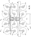
- FIGS. 1A and 1B illustrate one type of vehicle 100, namely, an aircraft, that may benefit from examples of the present disclosure.
- the vehicle generally includes a basic structure 102 with an airframe 104 with including a fuselage 106, and one or more pairs of wings 108 that extend from opposing sides of the fuselage.
- the airframe also includes an empennage or tail assembly 110 at a rear end of the fuselage, and the tail assembly includes a stabilizer 112.
- the vehicle 100 includes a plurality of power sources 114, and a propulsion system 116 including a plurality of electric motors 118 configured to power a plurality of propulsors 120 to generate propulsive forces that cause the vehicle to move.
- the vehicle as shown includes twelve electric motors (labeled M1 - M12), and the propulsors are rotors.
- the propulsors include one or more of rotors, propellers or wheels.
- the plurality of electric motors are mounted to the one or more pairs of wings 108, and each wing has multiple ones of the electric motors mounted to the wing.
- power distribution circuitry 122 electrically couples the plurality of power sources to the plurality of electric motors.
- the power distribution circuitry is configured to deliver electric power from the plurality of power sources to the plurality of electric motors.
- the power distribution circuitry 122 electrically couples the plurality of power sources 114 to the plurality of electric motors 118 in an interleaved topology.
- electric motors of the plurality of electric motors are alternately, electrically coupled to power sources of the plurality of power sources.
- Each of the electric motors is electrically coupled to a different one of the power sources than immediately adjacent ones of the electric motors.
- each of the electric motors is electrically coupled to a different one of the power sources than the immediately adjacent ones of the electric motors in either or both direction of a pitch axis or a roll axis of the vehicle.
- the interleaved topology in which the power distribution circuitry 122 electrically couples the plurality of power sources 114 to the plurality of electric motors 118 may be implemented in a number of different manners depending on the need or role of the electric motors.
- the first row of propulsors 120 are tilted relative to the other rows of propulsors.
- the first row of propulsors is primarily responsible for transition and forward flight (i.e., forward thrust). Higher redundancy may be required for the first row of propulsors relative to the other rows of propulsors.
- the electrical coupling may be distributed in a different manner or level.
- the plurality of electric motors 118 are mounted to the one or more pairs of wings 108, and each wing has multiple ones of the electric motors mounted to the wing.
- the multiple ones of the electric motors include at least a first electric motor and a second electric motor electrically coupled to respectively a first and a second of the power sources 114A, 114B.
- the multiple ones of the electric motors may include first electric motors M1, M3, M6, M8, M9, M11 , and second electric motors M2, M4, M5, M7, M10, M12 electrically coupled to respectively the first and the second of the power sources.
- FIGS. 2 , 3 , 4 and 5 illustrate power distribution circuitry that in various examples may correspond to the power distribution circuitry 122 shown in FIGS. 1A and 1B .
- the power distribution circuitry is shown and described herein in the context of a vehicle including a number of power sources, electric motors and propulsors. The numbers of these and other components shown in the figures are provided by way of example and should not be taken as limiting.
- the power distribution circuitry according to the various examples may electrically couple any number of power sources to any number of electric motors, according to examples of the present disclosure.
- FIG. 2 illustrates power distribution circuitry 200 according to some examples.
- the power distribution circuitry 200 includes a plurality of electric power buses 202 electrically coupling the plurality of power sources 114 to groups 204 of the plurality of electric motors 118.
- the power distribution circuitry includes a plurality of switches 206 electrically coupled to and between the plurality of power sources and the plurality of electric power buses, and one or more bus tie switches 208 electrically coupled to and between power buses of the plurality of power sources.
- the plurality of switches are closed during normal operation of the plurality of power sources, and the one or more bus tie switches are open during normal operation of the plurality of power sources.
- the power distribution circuitry includes power control circuitry 210 configured to control the plurality of switches 206 and the one or more bus tie switches 208 based on conditions of the plurality of power sources 114.
- the power control circuitry may include bus sensing circuitry, which may be implemented in a number of different manners.
- the bus sensing circuitry may be implemented using relays to sense input states of the plurality of power sources, and control the plurality of switches and the one or more bus tie switches. Other examples include sensing the input states of the plurality of power sources with voltage transducers, controlling the plurality of switches and the one or more bus tie switches with solid-state switches, and the like.
- the power control circuitry 210 is configured to open one of the plurality of switches 206 to disconnect a first of the plurality of power sources 114A from a first of the plurality of electric power buses 202A, and close one of the one or more bus tie switches 208 to connect the first of the plurality of electric power buses to a second of the plurality of electric power buses 202B.
- the power control circuitry is configured to open and close the respective switches, automatically in direct response to a fault or failure at the first of the plurality of power sources.
- the first of the plurality of electric power buses 202A and the second of the plurality of electric power buses 202B electrically couple the first of the plurality of power sources 114A and a second of the plurality of power sources 114B to respectively first and second groups 204A, 204B of the plurality of electric motors 118.
- the power control circuitry 210 is configured to open the one of the plurality of switches 206 and close the one of the one or more bus tie switches 208 to electrically couple the second of the plurality of power sources to the first and second groups of the plurality of electric motors.
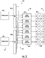
- FIG. 3 illustrates power distribution circuitry 300 according to other examples.
- the power distribution circuitry 300 includes a plurality of electric power buses 302 electrically coupling the plurality of power sources 114 to the plurality of electric motors 118.
- the power distribution circuitry includes a plurality of source-selection circuitries 304 that are separate and independent, and electrically coupled to and between the plurality of electric power buses and the plurality of electric motors.
- a group 306A of the plurality of source-selection circuitries 304 is configured to switchably connect a first or a second of the plurality of electric power buses 302A, 302B, and thereby a first or a second of the plurality of power sources 114A, 114B, to a first group 308A of the plurality of electric motors 118 based on conditions of the plurality of power sources 114.
- the plurality of source-selection circuitries is configured to connect the first of the plurality of electric power buses, and thereby the first of the plurality of power sources, to the first group of the plurality of electric motors during normal operation of the first of the plurality of power sources.
- the plurality of source-selection circuitries is configured to connect the second of the plurality of electric power buses, and thereby the second of the plurality of power sources, to the first group of the plurality of electric motors automatically in direct response to a fault or failure at the first of the plurality of power sources.
- a second group 306B of the plurality of source-selection circuitries 304 is configured to switchably connect the first or the second of the plurality of electric power buses 302A, 302B, and thereby the first or a second of the plurality of power sources 114A, 114B, to a second group 308B of the plurality of electric motors 118 based on conditions of the plurality of power sources 114.
- the second group of the plurality of source-selection circuitries is configured to connect the second of the plurality of electric power buses to the second group of the plurality of electric motors during normal operation of the second of the plurality of power sources.
- the second group of the plurality of source-selection circuitries is configured to connect the first of the plurality of electric power buses to the second group of the plurality of electric motors automatically in direct response to the fault or failure at the second of the plurality of power sources.
- FIG. 4 illustrates power distribution circuitry 400 according to yet other examples.
- the power distribution circuitry 400 includes a plurality of electric power buses 402 electrically coupling the plurality of power sources 114 to the plurality of electric motors 118.
- the power distribution circuitry includes a plurality of source-selection circuitries 404 that are separate and independent, and electrically coupled to and between the plurality of power sources and the plurality of electric power buses.
- a source-selection circuitry 404A of the plurality of source-selection circuitries 404 is configured to switchably connect a first or a second of the plurality of power sources 114A, 114B to a first of the plurality of electric power buses 402A based on a condition of the first of the plurality of power sources.
- the source-selection circuitry is configured to connect the first of the plurality of power sources to the first of the plurality of electric power buses during normal operation of the first of the plurality of power sources.
- the source-selection circuitry is configured to connect the second of the plurality of power sources to the first of the plurality of electric power buses automatically in direct response to a fault or failure at the first of the plurality of power sources.
- a second source-selection circuitry 404B of the plurality of source-selection circuitries 404 is configured to switchably connect a first or a second of the plurality of power sources 114A, 114B to a second of the plurality of electric power buses 402B based on a condition of the second of the plurality of power sources.
- the second source-selection circuitry is configured to connect the second of the plurality of power sources to the second of the plurality of electric power buses during normal operation of the second of the plurality of power sources.
- the second source-selection circuitry is configured to connect the first of the plurality of power sources to the second of the plurality of electric power buses automatically in direct response to the fault or failure at the second of the plurality of power sources.
- FIG. 5 illustrates power distribution circuitry 500 according to some examples.
- the power distribution circuitry 500 includes a plurality of electric power buses 502 with a plurality of feeders 504 electrically coupling the plurality of power sources 114 to the plurality of electric motors 118.
- the power distribution circuitry also includes a plurality of interlocks 506 electrically coupled to and between the plurality of feeders across the plurality of electric power buses.
- the interlocks include switches 508 that are open during normal operation of the plurality of power sources 114.
- the interlocks are configured to close a first of the switches 508A to connect a first feeder 504A of the first of the plurality of electric power buses 502A and one of the feeders 504C of a second of the plurality of electric power buses 502B.
- the interlocks are configured to close a second of the switches 508B to connect a second feeder 504B of the first of the plurality of electric power buses and one of the feeders 504D of a third of the plurality of electric power buses 502C.
- FIGS. 6A-6G are flowcharts illustrating various steps in a method 600 of managing power in a vehicle 100, according to various examples.
- the method includes providing the vehicle including a plurality of power sources 114, a propulsion system 116 including a plurality of electric motors 118 configured to power a plurality of propulsors 120 to generate propulsive forces that cause the vehicle to move, and power distribution circuitry 122, as shown at block 602 of FIG. 6A .
- the method also includes delivering direct current DC electric power from the plurality of power sources to the plurality of electric motors via the power distribution circuitry electrically coupling the plurality of power sources to the plurality of electric motors in an interleaved topology, as shown at block 604.
- each of the electric motors electrically coupled to a different one of the power sources than immediately adjacent ones of the electric motors.
- delivering the DC electric power at block 604 includes delivering the DC electric power via the power distribution circuitry 122 in which each of the electric motors 118 is electrically coupled to a different one of the power sources 114 than the immediately adjacent ones of the electric motors in either or both direction of a pitch axis or a roll axis of the vehicle 100.
- providing the vehicle 100 at block 602 includes providing the vehicle further including an airframe 104 with a fuselage 106 and one or more pairs of wings 108 that extend from opposing sides of the fuselage.
- the plurality of electric motors 118 are mounted to the one or more pairs of wings, and each wing has multiple ones of the electric motors mounted to the wing.
- delivering the DC electric power at block 604 includes delivering the DC electric power via the power distribution circuitry 122 in which the multiple ones of the electric motors 118 include at least a first electric motor (e.g., M1, M3, M6, M8, M9, M11 ) and a second electric motor (e.g., M2, M4, M5, M7, M10, M12 ) electrically coupled to respectively a first and a second of the power sources 114A, 114B.
- a first electric motor e.g., M1, M3, M6, M8, M9, M11
- a second electric motor e.g., M2, M4, M5, M7, M10, M12
- the power distribution circuitry 122, 200 includes a plurality of electric power buses 202 electrically coupling the plurality of power sources 114 to groups 204 of the plurality of electric motors 118.
- the power distribution circuitry also includes a plurality of switches 206 electrically coupled to and between the plurality of power sources and the plurality of electric power buses, and one or more bus tie switches 208 electrically coupled to and between power buses of the plurality of power sources. The plurality of switches and the one or more bus tie switches respectively closed and open during normal operation of the plurality of power sources.
- the method 600 further includes opening one of the plurality of switches to disconnect a first of the plurality of power sources 114A from a first of the plurality of electric power buses 202A, as shown at block 606 of FIG. 6B .
- the method also includes closing one of the one or more bus tie switches to connect the first of the plurality of electric power buses to a second of the plurality of electric power buses 202B, automatically in direct response to a fault or failure at the first of the plurality of power sources, as shown at block 608.
- the first of the plurality of electric power buses 202A and the second of the plurality of electric power buses 202B electrically couples the first of the plurality of power sources 114A and a second of the plurality of power sources 114B to respectively first and second groups 204A, 204B of the plurality of electric motors 118.
- the one of the plurality of switches is opened at block 606, and the one of the one or more bus tie switches is closed at block 608, to electrically couple the second of the plurality of power sources to the first and second groups of the plurality of electric motors.
- the power distribution circuitry 122, 300 includes a plurality of electric power buses 302 electrically coupling the plurality of power sources 114 to the plurality of electric motors 118.
- the power distribution circuitry also includes a plurality of source-selection circuitries 304 that are separate and independent, and electrically coupled to and between the plurality of electric power buses and the plurality of electric motors.
- the method 600 further includes a group 306A of the plurality of source-selection circuitries switchably connecting a first or a second of the plurality of electric power buses 302A, and thereby a first or a second of the plurality of power sources 114A, to a first group 308A of the plurality of electric motors, as shown at blocks 610 and 612 of FIG. 6C .
- the group of the plurality of source-selection circuitries connect the first of the plurality of electric power buses (and thereby the first of the plurality of power sources) to the first group of the plurality of electric motors during normal operation of the first of the plurality of power sources.
- the group of the plurality of source-selection circuitries connect the second of the plurality of electric power buses (and thereby the second of the plurality of power sources) to the first group of the plurality of electric motors automatically in direct response to a fault or failure at the first of the plurality of power sources.
- the method 600 further includes a second group 306B of the plurality of source-selection circuitries switchably connecting the first or the second of the plurality of electric power buses 302A, and thereby the first or the second of the plurality of power sources 114A, to a first group 308A of the plurality of electric motors, as shown at blocks 614 and 616 of FIG. 6D .
- the second group of the plurality of source-selection circuitries connect the second of the plurality of electric power buses (and thereby the second of the plurality of power sources) to the second group of the plurality of electric motors during normal operation of the second of the plurality of power sources.
- the second group of the plurality of source-selection circuitries connect the first of the plurality of electric power buses (and thereby the first of the plurality of power sources) to the second group of the plurality of electric motors automatically in direct response to a fault or failure at the second of the plurality of power sources.
- the power distribution circuitry 122, 400 includes a plurality of electric power buses 402 electrically coupling the plurality of power sources 114 to the plurality of electric motors 118.
- the power distribution circuitry also includes a plurality of source-selection circuitries 404 that are separate and independent, and electrically coupled to and between the plurality of power sources and the plurality of electric power buses.
- the method 600 in some of these examples further includes a source-selection circuitry 404A of the plurality of source-selection circuitries 404 switchably connecting a first or a second of the plurality of power sources 114A, 114B to a first of the plurality of electric power buses 402A, as shown at blocks 618 and 620 of FIG. 6E .
- the source-selection circuitry connects the first of the plurality of power sources to the first of the plurality of electric power buses during normal operation of the first of the plurality of power sources.
- the source-selection circuitry connects the second of the plurality of power sources to the first of the plurality of electric power buses automatically in direct response to a fault or failure at the first of the plurality of power sources.
- the method 600 further includes a second source-selection circuitry 404B of the plurality of source-selection circuitries 404 switchably connecting the first or the second of the plurality of power sources 114A, 114B to a second of the plurality of electric power buses 402B, as shown at blocks 622 and 624 of FIG. 6F .
- the second source-selection circuitry connects the second of the plurality of power sources to the second of the plurality of electric power buses during normal operation of the second of the plurality of power sources.
- the second source-selection circuitry connects the first of the plurality of power sources to the second of the plurality of electric power buses automatically in direct response to a fault or failure at the second of the plurality of power sources.
- the power distribution circuitry 122, 500 includes a plurality of electric power buses 502 with a plurality of feeders 504 electrically coupling the plurality of power sources 114 to the plurality of electric motors 118, and a plurality of interlocks 506 electrically coupled to and between the plurality of feeders across the plurality of electric power buses.
- the method 600 further includes interlocks of the plurality of interlocks electrically coupling feeders of a first of the plurality of electric power buses 502A to different feeders of different ones of others of the plurality of electric power buses 502B, 502C, automatically and in direct response to a fault or failure at a first of the plurality of power sources 114A electrically coupled to the first of the plurality of electric power buses, as shown at block 626 of FIG. 6G .
- the interlocks include switches 508 that are open during normal operation of the plurality of power sources 114.
- the interlocks electrically coupling the feeders at block 626 includes the interlocks closing a first of the switches 508A to connect a first feeder 504A of the first of the plurality of electric power buses 502A and one of the feeders 504C of a second of the plurality of electric power buses 502B, as shown at block 628.
- the interlocks also close a second of the switches 508B to connect a second feeder 504B of the first of the plurality of electric power buses and one of the feeders 504D of a third of the plurality of electric power buses 502C, as shown at block 630.
Abstract
Description
- The present disclosure relates generally to electric power distribution and, in particular, to electric power distribution in electrically-powered systems such as those onboard vehicles.
- Electric and hybrid vehicles such as aerial vehicles, road vehicles and the like are powered by sources of electric power such as batteries. These vehicles generally include one or more power sources, and a propulsion system one or more electric motors configured to power one or more propulsors to generate propulsive forces that cause the vehicle to move. Depending on the vehicle, these propulsors may include rotors, propellers, wheels and the like. The propulsion system may also include a drivetrain configured to deliver power from the electric motors to the propulsors; and for some vehicles, the electric motors and drivetrain may in some contexts be referred to as the powertrain of the vehicle.
- In many of these vehicles, electric power from the power sources is distributed to the electric motors via a centralized electric power distribution box designed to facilitate electric source switchover and back up in cases of certain failure modes. Existing power distribution designs usually have multiple channels of power sources, with centralized monitoring and a control unit to detect failures and control connections between sources and loads. Some design instances use additional channel via a dissimilar apparatus, and this channel is designed to have higher reliability for certain equipment such as navigation equipment in the case of air vehicles.
- As explained above, existing power distribution designs in electric and hybrid vehicles have provided back-up or failure isolation with a centralized electric power distribution box. New propulsion architectures in vehicles that use distributed propulsors driven by individual electric motors at the propulsors has provided opportunity to simplify the centralized electric power distribution box with self-arbitration between the available power sources, and improved back up and failure isolation coverage as well as propulsion system reliability.
- Examples of the present disclosure are directed to electric power distribution and, in particular, to electric power distribution in electrically-powered systems such as those onboard vehicles. A vehicle according to some examples includes a plurality of power sources, and a propulsion system including a plurality of electric motors configured to power a plurality of propulsors. The vehicle also includes power distribution circuitry that electrically couples the plurality of power sources to the plurality of electric motors, such as in an interleaved topology in which electric motors of the plurality of electric motors are alternately, electrically coupled to power sources of the plurality of power sources. Examples employ self-control fault tolerance that selects between power sources based on their condition as operating normally or having a fault or failure.
- The present disclosure thus includes, without limitation, the following examples.
- Some examples provide a vehicle comprising: a basic structure; and coupled to the basic structure, a plurality of power sources; a propulsion system including a plurality of electric motors configured to power a plurality of propulsors to generate propulsive forces that cause the vehicle to move; and power distribution circuitry configured to deliver direct current (DC) electric power from the plurality of power sources to the plurality of electric motors, the power distribution circuitry electrically coupling the plurality of power sources to the plurality of electric motors in an interleaved topology in which electric motors of the plurality of electric motors are alternately, electrically coupled to power sources of the plurality of power sources, each of the electric motors electrically coupled to a different one of the power sources than immediately adjacent ones of the electric motors.
- In some examples of the vehicle of any preceding example, or any combination of any preceding examples, the plurality of propulsors include one or more of rotors, propellers or wheels.
- In some examples of the vehicle of any preceding example, or any combination of any preceding examples, each of the electric motors is electrically coupled to a different one of the power sources than the immediately adjacent ones of the electric motors in either or both direction of a pitch axis or a roll axis of the vehicle.
- In some examples of the vehicle of any preceding example, or any combination of any preceding example, the basic structure includes an airframe with a fuselage and one or more pairs of wings that extend from opposing sides of the fuselage, the plurality of electric motors are mounted to the one or more pairs of wings, and each wing has multiple ones of the electric motors mounted to the wing.
- In some examples of the vehicle of any preceding example, or any combination of any preceding examples, the multiple ones of the electric motors include at least a first electric motor and a second electric motor electrically coupled to respectively a first and a second of the power sources.
- In some examples of the vehicle of any preceding example, or any combination of any preceding examples, the power distribution circuitry includes: a plurality of electric power buses electrically coupling the plurality of power sources to groups of the plurality of electric motors; a plurality of switches electrically coupled to and between the plurality of power sources and the plurality of electric power buses, the plurality of switches closed during normal operation of the plurality of power sources; one or more bus tie switches electrically coupled to and between power buses of the plurality of power sources, the one or more bus tie switches open during normal operation of the plurality of power sources; and power control circuitry configured to open one of the plurality of switches to disconnect a first of the plurality of power sources from a first of the plurality of electric power buses, and close one of the one or more bus tie switches to connect the first of the plurality of electric power buses to a second of the plurality of electric power buses, automatically in direct response to a fault or failure at the first of the plurality of power sources.
- In some examples of the vehicle of any preceding example, or any combination of any preceding examples, the first of the plurality of electric power buses and the second of the plurality of electric power buses electrically couples the first of the plurality of power sources and a second of the plurality of power sources to respectively first and second groups of the plurality of electric motors, and wherein the power control circuitry is configured to open the one of the plurality of switches and close the one of the one or more bus tie switches to electrically couple the second of the plurality of power sources to the first and second groups of the plurality of electric motors.
- In some examples of the vehicle of any preceding example, or any combination of any preceding examples, the power distribution circuitry includes: a plurality of electric power buses electrically coupling the plurality of power sources to the plurality of electric motors; and a plurality of source-selection circuitries that are separate and independent, and electrically coupled to and between the plurality of electric power buses and the plurality of electric motors, and wherein a group of the plurality of source-selection circuitries is configured to switchably connect a first of the plurality of electric power buses and thereby a first of the plurality of power sources to a first group of the plurality of electric motors during normal operation of the first of the plurality of power sources, and a second of the plurality of electric power buses and thereby a second of the plurality of power sources to the first group of the plurality of electric motors automatically in direct response to a fault or failure at the first of the plurality of power sources.
- In some examples of the vehicle of any preceding example, or any combination of any preceding examples, a second group of the plurality of source-selection circuitries is configured to switchably connect the second of the plurality of electric power buses to a second group of the plurality of electric motors during normal operation of the second of the plurality of power sources, and the first of the plurality of electric power buses to the second group of the plurality of electric motors automatically in direct response to the fault or failure at the second of the plurality of power sources.
- In some examples of the vehicle of any preceding example, or any combination of any preceding examples, the power distribution circuitry includes: a plurality of electric power buses electrically coupling the plurality of power sources to the plurality of electric motors; a plurality of source-selection circuitries that are separate and independent, and electrically coupled to and between the plurality of power sources and the plurality of electric power buses, and wherein a source-selection circuitry of the plurality of source-selection circuitries is configured to switchably connect a first of the plurality of power sources to a first of the plurality of electric power buses during normal operation of the first of the plurality of power sources, and a second of the plurality of power sources to the first of the plurality of electric power buses automatically in direct response to a fault or failure at the first of the plurality of power sources.
- In some examples of the vehicle of any preceding example, or any combination of any preceding examples, a second source-selection circuitry of the plurality of source-selection circuitries is configured to switchably connect the second of the plurality of power sources to the second of the plurality of electric power buses during normal operation of the second of the plurality of power sources, and the first of the plurality of power sources to the second of the plurality of electric power buses automatically in direct response to the fault or failure at the second of the plurality of power sources.
- In some examples of the vehicle of any preceding example, or any combination of any preceding examples, the power distribution circuitry includes: a plurality of electric power buses with a plurality of feeders electrically coupling the plurality of power sources to the plurality of electric motors; and a plurality of interlocks electrically coupled to and between the plurality of feeders across the plurality of electric power buses, including interlocks configured to electrically couple feeders of a first of the plurality of electric power buses to different feeders of different ones of others of the plurality of electric power buses, automatically and in direct response to a fault or failure at a first of the plurality of power sources electrically coupled to the first of the plurality of electric power buses.
- In some examples of the vehicle of any preceding example, or any combination of any preceding examples, the interlocks include switches that are open during normal operation of the plurality of power sources, and the interlocks are configured to close a first of the switches to connect a first feeder of the first of the plurality of electric power buses and one of the feeders of a second of the plurality of electric power buses, and close a second of the switches to connect a second feeder of the first of the plurality of electric power buses and one of the feeders of a third of the plurality of electric power buses.
- Some examples provide a method of managing power in a vehicle, the method comprising: providing the vehicle including a plurality of power sources, a propulsion system including a plurality of electric motors configured to power a plurality of propulsors to generate propulsive forces that cause the vehicle to move, and power distribution circuitry; and delivering direct current (DC) electric power from the plurality of power sources to the plurality of electric motors via the power distribution circuitry electrically coupling the plurality of power sources to the plurality of electric motors in an interleaved topology in which electric motors of the plurality of electric motors are alternately, electrically coupled to power sources of the plurality of power sources, each of the electric motors electrically coupled to a different one of the power sources than immediately adjacent ones of the electric motors.
- In some examples of the method of any preceding example, or any combination of any preceding examples, delivering the DC electric power includes delivering the DC electric power via the power distribution circuitry in which each of the electric motors is electrically coupled to a different one of the power sources than the immediately adjacent ones of the electric motors in either or both direction of a pitch axis or a roll axis of the vehicle.
- In some examples of the method of any preceding example, or any combination of any preceding examples, providing the vehicle includes providing the vehicle further including an airframe with a fuselage and one or more pairs of wings that extend from opposing sides of the fuselage, the plurality of electric motors are mounted to the one or more pairs of wings, and each wing has multiple ones of the electric motors mounted to the wing.
- In some examples of the method of any preceding example, or any combination of any preceding examples, delivering the DC electric power includes delivering the DC electric power via the power distribution circuitry in which the multiple ones of the electric motors include at least a first electric motor and a second electric motor electrically coupled to respectively a first and a second of the power sources.
- In some examples of the method of any preceding example, or any combination of any preceding examples, the power distribution circuitry includes a plurality of electric power buses electrically coupling the plurality of power sources to groups of the plurality of electric motors, a plurality of switches electrically coupled to and between the plurality of power sources and the plurality of electric power buses, and one or more bus tie switches electrically coupled to and between power buses of the plurality of power sources, the plurality of switches and the one or more bus tie switches respectively closed and open during normal operation of the plurality of power sources, and wherein the method further comprises opening one of the plurality of switches to disconnect a first of the plurality of power sources from a first of the plurality of electric power buses, and closing one of the one or more bus tie switches to connect the first of the plurality of electric power buses to a second of the plurality of electric power buses, automatically in direct response to a fault or failure at the first of the plurality of power sources.
- In some examples of the method of any preceding example, or any combination of any preceding examples, the first of the plurality of electric power buses and the second of the plurality of electric power buses electrically couples the first of the plurality of power sources and a second of the plurality of power sources to respectively first and second groups of the plurality of electric motors, and wherein the one of the plurality of switches is opened, and the one of the one or more bus tie switches is closed, to electrically couple the second of the plurality of power sources to the first and second groups of the plurality of electric motors.
- In some examples of the method of any preceding example, or any combination of any preceding examples, the power distribution circuitry includes a plurality of electric power buses electrically coupling the plurality of power sources to the plurality of electric motors, and a plurality of source-selection circuitries that are separate and independent, and electrically coupled to and between the plurality of electric power buses and the plurality of electric motors, and wherein the method further comprises a group of the plurality of source-selection circuitries switchably connecting a first of the plurality of electric power buses and thereby a first of the plurality of power sources to a first group of the plurality of electric motors during normal operation of the first of the plurality of power sources, and a second of the plurality of electric power buses and thereby a second of the plurality of power sources to the first group of the plurality of electric motors automatically in direct response to a fault or failure at the first of the plurality of power sources.
- In some examples of the method of any preceding example, or any combination of any preceding examples, the method further comprises a second group of the plurality of source-selection circuitries switchably connecting the second of the plurality of electric power buses to a second group of the plurality of electric motors during normal operation of the second of the plurality of power sources, and the first of the plurality of electric power buses to the second group of the plurality of electric motors automatically in direct response to the fault or failure at the second of the plurality of power sources.
- In some examples of the method of any preceding example, or any combination of any preceding examples, the power distribution circuitry includes a plurality of electric power buses electrically coupling the plurality of power sources to the plurality of electric motors, and a plurality of source-selection circuitries that are separate and independent, and electrically coupled to and between the plurality of power sources and the plurality of electric power buses, and wherein the method further comprises a source-selection circuitry of the plurality of source-selection circuitries switchably connecting a first of the plurality of power sources to a first of the plurality of electric power buses during normal operation of the first of the plurality of power sources, and a second of the plurality of power sources to the first of the plurality of electric power buses automatically in direct response to a fault or failure at the first of the plurality of power sources.
- In some examples of the method of any preceding example, or any combination of any preceding examples, the method further comprises a second source-selection circuitry of the plurality of source-selection circuitries switchably connecting the second of the plurality of power sources to the second of the plurality of electric power buses during normal operation of the second of the plurality of power sources, and the first of the plurality of power sources to the second of the plurality of electric power buses automatically in direct response to the fault or failure at the second of the plurality of power sources.
- In some examples of the method of any preceding example, or any combination of any preceding examples, the power distribution circuitry includes a plurality of electric power buses with a plurality of feeders electrically coupling the plurality of power sources to the plurality of electric motors, and a plurality of interlocks electrically coupled to and between the plurality of feeders across the plurality of electric power buses, and wherein the method further comprises interlocks of the plurality of interlocks electrically coupling feeders of a first of the plurality of electric power buses to different feeders of different ones of others of the plurality of electric power buses, automatically and in direct response to a fault or failure at a first of the plurality of power sources electrically coupled to the first of the plurality of electric power buses.
- In some examples of the method of any preceding example, or any combination of any preceding examples, the interlocks include switches that are open during normal operation of the plurality of power sources, and wherein the interlocks electrically coupling the feeders includes the interlocks closing a first of the switches to connect a first feeder of the first of the plurality of electric power buses and one of the feeders of a second of the plurality of electric power buses, and closing a second of the switches to connect a second feeder of the first of the plurality of electric power buses and one of the feeders of a third of the plurality of electric power buses.
- These and other features, examples, and advantages of the present disclosure will be apparent from a reading of the following detailed description together with the accompanying figures, which are briefly described below. The present disclosure includes any combination of two, three, four or more features or elements set forth in this disclosure, regardless of whether such features or elements are expressly combined or otherwise recited in a specific example described herein. This disclosure is intended to be read holistically such that any separable features or elements of the disclosure, in any of its examples, should be viewed as combinable unless the context of the disclosure clearly dictates otherwise.
- It will therefore be appreciated that this Brief Summary is provided merely for purposes of summarizing some examples so as to provide a basic understanding of some examples of the disclosure. Accordingly, it will be appreciated that the above described examples should not be construed to narrow the scope of the disclosure in any way. Other examples and advantages will become apparent from the following detailed description taken in conjunction with the accompanying figures which illustrate, by way of example, the principles of some described examples.
- Having thus described examples of the disclosure in general terms, reference will now be made to the accompanying figures, which are not necessarily drawn to scale, and wherein:
-
FIGS. 1A and1B illustrate one type of vehicle, namely, an aircraft; -
FIGS. 2 ,3 ,4 and5 illustrate power distribution circuitry; and -
FIGS. 6A, 6B ,6C, 6D ,6E, 6F and6G are flowcharts illustrating various steps in a method of managing power in a vehicle. - Some examples of the present disclosure will now be described more fully hereinafter with reference to the accompanying figures, in which some, but not all examples of the disclosure are shown. Indeed, various examples of the disclosure may be embodied in many different forms and should not be construed as limited to the examples set forth herein; rather, these examples are provided so that this disclosure will be thorough and complete, and will fully convey the scope of the disclosure to those skilled in the art. Like reference numerals refer to like elements throughout.
- Unless specified otherwise or clear from context, references to first, second or the like should not be construed to imply a particular order. A feature described as being above another feature (unless specified otherwise or clear from context) may instead be below, and vice versa; and similarly, features described as being to the left of another feature else may instead be to the right, and vice versa. Also, while reference may be made herein to quantitative measures, values, geometric relationships or the like, unless otherwise stated, any one or more if not all of these may be absolute or approximate to account for acceptable variations that may occur, such as those due to engineering tolerances or the like.
- As used herein, unless specified otherwise or clear from context, the "or" of a set of operands is the "inclusive or" and thereby true if and only if one or more of the operands is true, as opposed to the "exclusive or" which is false when all of the operands are true. Thus, for example, "[A] or [B]" is true if [A] is true, or if [B] is true, or if both [A] and [B] are true. Further, the articles "a" and "an" mean "one or more," unless specified otherwise or clear from context to be directed to a singular form. Furthermore, it should be understood that unless otherwise specified, the terms "data," "content," "digital content," "information," and similar terms may be at times used interchangeably.
- Examples of the present disclosure relate generally to electric power distribution and, in particular, to electric power distribution in electrically-powered systems such as those onboard vehicles. As used herein, a vehicle is a machine designed as an instrument of conveyance by land, water or air. A vehicle designed and configurable to fly may at times be referred to as an aerial vehicle or aircraft. A vehicle designed and configurable to operate with at least some level of autonomy may at times be referred to as an autonomous vehicle, or an autonomous aerial vehicle or aircraft in the case of an autonomous vehicle that is also designed and configurable to fly. Other examples of suitable vehicles include a variety of road vehicles, railed vehicles, watercraft (surface vessels, underwater vessels), amphibious vehicles, spacecraft and the like. In some examples, the vehicle is an electric vehicle such as an electric road or rail vehicle, an electric aircraft, an electric spacecraft or the like.
- The vehicle may be manned or unmanned. The vehicle may be fully human-controlled, or the vehicle may be semi-autonomous or autonomous in which at least some of its maneuvers are executed independent of or with minimal human intervention. In some examples, the vehicle is operable in various modes with various amounts of human control.
- A vehicle generally includes a basic structure; and coupled to the basic structure, a power source, power distribution circuitry and a propulsion system. The basic structure is the main supporting structure of the vehicle to which other components are attached. The basic structure is the load-bearing framework of the vehicle that structurally supports the vehicle in its construction and function. In various contexts, the basic structure may be referred to as a chassis, an airframe or the like.
- The power source is a source of power such as electric power from which the vehicle is powered to move; and in some examples, the vehicle includes multiple or a plurality of power sources. Examples of suitable power sources include batteries, solar panels, fuel cells, electric generators and the like. The power distribution circuitry includes power transmission lines, power electronics and other circuitry for distribution of power from the power source to an electrical load such as the propulsion system and other onboard electronics.
- The propulsion system includes one or more electric motors configured to power one or more propulsors to generate propulsive forces that cause the vehicle to move. Although not separately shown, in some examples, one or more motor controllers may be included to coordinate performance of the one or more electric motors. A propulsor is any of a number of different means of converting power into a propulsive force. Examples of suitable propulsors include rotors, propellers, wheels and the like. In some examples, the propulsion system includes a drivetrain configured to deliver power from the electric motors to the propulsors. The electric motors and drivetrain may in some contexts be referred to as the powertrain of the vehicle.
- The vehicle may also include any of a number of other systems, subsystems, components and the like. In particular, for example, the vehicle may include a vehicle management system (VMS). The VMS is a vehicle-specific subsystem configured to manage subsystems and other components of the vehicle. These subsystems and other components include, for example, maneuver controls, landing gear, onboard environmental systems, electrical, pneumatic and hydraulic systems, communications systems, navigation systems and other subsystems and components for controlling operation and maneuvering of the vehicle. The VMS is configured to accept maneuver commands such as waypoints and/or steering commands, and control the vehicle to follow those maneuver commands.
-
FIGS. 1A and1B illustrate one type ofvehicle 100, namely, an aircraft, that may benefit from examples of the present disclosure. As shown, the vehicle generally includes abasic structure 102 with anairframe 104 with including afuselage 106, and one or more pairs ofwings 108 that extend from opposing sides of the fuselage. The airframe also includes an empennage ortail assembly 110 at a rear end of the fuselage, and the tail assembly includes astabilizer 112. - The
vehicle 100 includes a plurality ofpower sources 114, and apropulsion system 116 including a plurality ofelectric motors 118 configured to power a plurality ofpropulsors 120 to generate propulsive forces that cause the vehicle to move. The vehicle as shown includes twelve electric motors (labeled M1 - M12), and the propulsors are rotors. Depending on the vehicle, in various examples, the propulsors include one or more of rotors, propellers or wheels. Also in the vehicle as shown, the plurality of electric motors are mounted to the one or more pairs ofwings 108, and each wing has multiple ones of the electric motors mounted to the wing. As also shown,power distribution circuitry 122 electrically couples the plurality of power sources to the plurality of electric motors. The power distribution circuitry is configured to deliver electric power from the plurality of power sources to the plurality of electric motors. - As shown more particularly in
FIG. 1B , according to some examples of the present disclosure, thepower distribution circuitry 122 electrically couples the plurality ofpower sources 114 to the plurality ofelectric motors 118 in an interleaved topology. In some examples of this topology, electric motors of the plurality of electric motors are alternately, electrically coupled to power sources of the plurality of power sources. Each of the electric motors is electrically coupled to a different one of the power sources than immediately adjacent ones of the electric motors. In some examples, each of the electric motors is electrically coupled to a different one of the power sources than the immediately adjacent ones of the electric motors in either or both direction of a pitch axis or a roll axis of the vehicle. - The interleaved topology in which the
power distribution circuitry 122 electrically couples the plurality ofpower sources 114 to the plurality ofelectric motors 118 may be implemented in a number of different manners depending on the need or role of the electric motors. In thevehicle 100 as shown, the first row ofpropulsors 120 are tilted relative to the other rows of propulsors. The first row of propulsors is primarily responsible for transition and forward flight (i.e., forward thrust). Higher redundancy may be required for the first row of propulsors relative to the other rows of propulsors. In other configurations, the electrical coupling may be distributed in a different manner or level. - In some examples in which the
vehicle 100 is an aircraft, the plurality ofelectric motors 118 are mounted to the one or more pairs ofwings 108, and each wing has multiple ones of the electric motors mounted to the wing. In some of these examples, the multiple ones of the electric motors include at least a first electric motor and a second electric motor electrically coupled to respectively a first and a second of thepower sources -
FIGS. 2 ,3 ,4 and5 illustrate power distribution circuitry that in various examples may correspond to thepower distribution circuitry 122 shown inFIGS. 1A and1B . The power distribution circuitry is shown and described herein in the context of a vehicle including a number of power sources, electric motors and propulsors. The numbers of these and other components shown in the figures are provided by way of example and should not be taken as limiting. The power distribution circuitry according to the various examples may electrically couple any number of power sources to any number of electric motors, according to examples of the present disclosure. -
FIG. 2 illustrates power distribution circuitry 200 according to some examples. As shown, the power distribution circuitry 200 includes a plurality ofelectric power buses 202 electrically coupling the plurality ofpower sources 114 togroups 204 of the plurality ofelectric motors 118. The power distribution circuitry includes a plurality ofswitches 206 electrically coupled to and between the plurality of power sources and the plurality of electric power buses, and one or more bus tie switches 208 electrically coupled to and between power buses of the plurality of power sources. The plurality of switches are closed during normal operation of the plurality of power sources, and the one or more bus tie switches are open during normal operation of the plurality of power sources. - As also shown, the power distribution circuitry includes power control circuitry 210 configured to control the plurality of
switches 206 and the one or more bus tie switches 208 based on conditions of the plurality ofpower sources 114. Although not separately shown, the power control circuitry may include bus sensing circuitry, which may be implemented in a number of different manners. The bus sensing circuitry may be implemented using relays to sense input states of the plurality of power sources, and control the plurality of switches and the one or more bus tie switches. Other examples include sensing the input states of the plurality of power sources with voltage transducers, controlling the plurality of switches and the one or more bus tie switches with solid-state switches, and the like. - According to some examples, the power control circuitry 210 is configured to open one of the plurality of
switches 206 to disconnect a first of the plurality ofpower sources 114A from a first of the plurality of electric power buses 202A, and close one of the one or more bus tie switches 208 to connect the first of the plurality of electric power buses to a second of the plurality ofelectric power buses 202B. In this regard, the power control circuitry is configured to open and close the respective switches, automatically in direct response to a fault or failure at the first of the plurality of power sources. - In some further examples, the first of the plurality of electric power buses 202A and the second of the plurality of
electric power buses 202B electrically couple the first of the plurality ofpower sources 114A and a second of the plurality ofpower sources 114B to respectively first andsecond groups electric motors 118. In some of these examples, the power control circuitry 210 is configured to open the one of the plurality ofswitches 206 and close the one of the one or more bus tie switches 208 to electrically couple the second of the plurality of power sources to the first and second groups of the plurality of electric motors. -
FIG. 3 illustratespower distribution circuitry 300 according to other examples. As shown, thepower distribution circuitry 300 includes a plurality ofelectric power buses 302 electrically coupling the plurality ofpower sources 114 to the plurality ofelectric motors 118. The power distribution circuitry includes a plurality of source-selection circuitries 304 that are separate and independent, and electrically coupled to and between the plurality of electric power buses and the plurality of electric motors. - According to some examples, a
group 306A of the plurality of source-selection circuitries 304 is configured to switchably connect a first or a second of the plurality ofelectric power buses power sources electric motors 118 based on conditions of the plurality ofpower sources 114. In this regard, in some examples, the plurality of source-selection circuitries is configured to connect the first of the plurality of electric power buses, and thereby the first of the plurality of power sources, to the first group of the plurality of electric motors during normal operation of the first of the plurality of power sources. The plurality of source-selection circuitries is configured to connect the second of the plurality of electric power buses, and thereby the second of the plurality of power sources, to the first group of the plurality of electric motors automatically in direct response to a fault or failure at the first of the plurality of power sources. - In some further examples, a
second group 306B of the plurality of source-selection circuitries 304 is configured to switchably connect the first or the second of the plurality ofelectric power buses power sources second group 308B of the plurality ofelectric motors 118 based on conditions of the plurality ofpower sources 114. The second group of the plurality of source-selection circuitries is configured to connect the second of the plurality of electric power buses to the second group of the plurality of electric motors during normal operation of the second of the plurality of power sources. The second group of the plurality of source-selection circuitries is configured to connect the first of the plurality of electric power buses to the second group of the plurality of electric motors automatically in direct response to the fault or failure at the second of the plurality of power sources. -
FIG. 4 illustratespower distribution circuitry 400 according to yet other examples. As shown, thepower distribution circuitry 400 includes a plurality ofelectric power buses 402 electrically coupling the plurality ofpower sources 114 to the plurality ofelectric motors 118. The power distribution circuitry includes a plurality of source-selection circuitries 404 that are separate and independent, and electrically coupled to and between the plurality of power sources and the plurality of electric power buses. - According to some of these examples, a source-
selection circuitry 404A of the plurality of source-selection circuitries 404 is configured to switchably connect a first or a second of the plurality ofpower sources electric power buses 402A based on a condition of the first of the plurality of power sources. The source-selection circuitry is configured to connect the first of the plurality of power sources to the first of the plurality of electric power buses during normal operation of the first of the plurality of power sources. The source-selection circuitry is configured to connect the second of the plurality of power sources to the first of the plurality of electric power buses automatically in direct response to a fault or failure at the first of the plurality of power sources. - In some further examples, a second source-
selection circuitry 404B of the plurality of source-selection circuitries 404 is configured to switchably connect a first or a second of the plurality ofpower sources electric power buses 402B based on a condition of the second of the plurality of power sources. The second source-selection circuitry is configured to connect the second of the plurality of power sources to the second of the plurality of electric power buses during normal operation of the second of the plurality of power sources. And the second source-selection circuitry is configured to connect the first of the plurality of power sources to the second of the plurality of electric power buses automatically in direct response to the fault or failure at the second of the plurality of power sources. -
FIG. 5 illustratespower distribution circuitry 500 according to some examples. As shown, thepower distribution circuitry 500 includes a plurality ofelectric power buses 502 with a plurality offeeders 504 electrically coupling the plurality ofpower sources 114 to the plurality ofelectric motors 118. The power distribution circuitry also includes a plurality ofinterlocks 506 electrically coupled to and between the plurality of feeders across the plurality of electric power buses. This includes interlocks configured to electrically couple feeders of a first of the plurality ofelectric power buses 502A to different feeders of different ones of others of the plurality ofelectric power buses power sources 114A electrically coupled to the first of the plurality of electric power buses. - In some further examples, the interlocks include switches 508 that are open during normal operation of the plurality of
power sources 114. In some of these examples, the interlocks are configured to close a first of theswitches 508A to connect afirst feeder 504A of the first of the plurality ofelectric power buses 502A and one of thefeeders 504C of a second of the plurality ofelectric power buses 502B. Likewise, the interlocks are configured to close a second of theswitches 508B to connect asecond feeder 504B of the first of the plurality of electric power buses and one of thefeeders 504D of a third of the plurality ofelectric power buses 502C. -
FIGS. 6A-6G are flowcharts illustrating various steps in amethod 600 of managing power in avehicle 100, according to various examples. The method includes providing the vehicle including a plurality ofpower sources 114, apropulsion system 116 including a plurality ofelectric motors 118 configured to power a plurality ofpropulsors 120 to generate propulsive forces that cause the vehicle to move, andpower distribution circuitry 122, as shown atblock 602 ofFIG. 6A . The method also includes delivering direct current DC electric power from the plurality of power sources to the plurality of electric motors via the power distribution circuitry electrically coupling the plurality of power sources to the plurality of electric motors in an interleaved topology, as shown atblock 604. Again, in this topology, which electric motors of the plurality of electric motors are alternately, electrically coupled to power sources of the plurality of power sources, each of the electric motors electrically coupled to a different one of the power sources than immediately adjacent ones of the electric motors. - In some examples, delivering the DC electric power at
block 604 includes delivering the DC electric power via thepower distribution circuitry 122 in which each of theelectric motors 118 is electrically coupled to a different one of thepower sources 114 than the immediately adjacent ones of the electric motors in either or both direction of a pitch axis or a roll axis of thevehicle 100. - In some examples, providing the
vehicle 100 atblock 602 includes providing the vehicle further including anairframe 104 with afuselage 106 and one or more pairs ofwings 108 that extend from opposing sides of the fuselage. In some of these examples, the plurality ofelectric motors 118 are mounted to the one or more pairs of wings, and each wing has multiple ones of the electric motors mounted to the wing. - In some examples, delivering the DC electric power at
block 604 includes delivering the DC electric power via thepower distribution circuitry 122 in which the multiple ones of theelectric motors 118 include at least a first electric motor (e.g., M1, M3, M6, M8, M9, M11) and a second electric motor (e.g., M2, M4, M5, M7, M10, M12) electrically coupled to respectively a first and a second of thepower sources - In some examples, the
power distribution circuitry 122, 200 includes a plurality ofelectric power buses 202 electrically coupling the plurality ofpower sources 114 togroups 204 of the plurality ofelectric motors 118. The power distribution circuitry also includes a plurality ofswitches 206 electrically coupled to and between the plurality of power sources and the plurality of electric power buses, and one or more bus tie switches 208 electrically coupled to and between power buses of the plurality of power sources. The plurality of switches and the one or more bus tie switches respectively closed and open during normal operation of the plurality of power sources. - Also in some of these examples, the
method 600 further includes opening one of the plurality of switches to disconnect a first of the plurality ofpower sources 114A from a first of the plurality of electric power buses 202A, as shown atblock 606 ofFIG. 6B . The method also includes closing one of the one or more bus tie switches to connect the first of the plurality of electric power buses to a second of the plurality ofelectric power buses 202B, automatically in direct response to a fault or failure at the first of the plurality of power sources, as shown atblock 608. - In some further examples, the first of the plurality of electric power buses 202A and the second of the plurality of
electric power buses 202B electrically couples the first of the plurality ofpower sources 114A and a second of the plurality ofpower sources 114B to respectively first andsecond groups electric motors 118. In some of these examples, the one of the plurality of switches is opened atblock 606, and the one of the one or more bus tie switches is closed atblock 608, to electrically couple the second of the plurality of power sources to the first and second groups of the plurality of electric motors. - In some examples, the
power distribution circuitry electric power buses 302 electrically coupling the plurality ofpower sources 114 to the plurality ofelectric motors 118. The power distribution circuitry also includes a plurality of source-selection circuitries 304 that are separate and independent, and electrically coupled to and between the plurality of electric power buses and the plurality of electric motors. - Also in some of these examples, the
method 600 further includes agroup 306A of the plurality of source-selection circuitries switchably connecting a first or a second of the plurality ofelectric power buses 302A, and thereby a first or a second of the plurality ofpower sources 114A, to a first group 308A of the plurality of electric motors, as shown atblocks 610 and 612 ofFIG. 6C . The group of the plurality of source-selection circuitries connect the first of the plurality of electric power buses (and thereby the first of the plurality of power sources) to the first group of the plurality of electric motors during normal operation of the first of the plurality of power sources. And the group of the plurality of source-selection circuitries connect the second of the plurality of electric power buses (and thereby the second of the plurality of power sources) to the first group of the plurality of electric motors automatically in direct response to a fault or failure at the first of the plurality of power sources. - In some further examples, the
method 600 further includes asecond group 306B of the plurality of source-selection circuitries switchably connecting the first or the second of the plurality ofelectric power buses 302A, and thereby the first or the second of the plurality ofpower sources 114A, to a first group 308A of the plurality of electric motors, as shown atblocks FIG. 6D . The second group of the plurality of source-selection circuitries connect the second of the plurality of electric power buses (and thereby the second of the plurality of power sources) to the second group of the plurality of electric motors during normal operation of the second of the plurality of power sources. And the second group of the plurality of source-selection circuitries connect the first of the plurality of electric power buses (and thereby the first of the plurality of power sources) to the second group of the plurality of electric motors automatically in direct response to a fault or failure at the second of the plurality of power sources. - In some examples, the
power distribution circuitry electric power buses 402 electrically coupling the plurality ofpower sources 114 to the plurality ofelectric motors 118. The power distribution circuitry also includes a plurality of source-selection circuitries 404 that are separate and independent, and electrically coupled to and between the plurality of power sources and the plurality of electric power buses. - The
method 600 in some of these examples further includes a source-selection circuitry 404A of the plurality of source-selection circuitries 404 switchably connecting a first or a second of the plurality ofpower sources electric power buses 402A, as shown atblocks FIG. 6E . The source-selection circuitry connects the first of the plurality of power sources to the first of the plurality of electric power buses during normal operation of the first of the plurality of power sources. And the source-selection circuitry connects the second of the plurality of power sources to the first of the plurality of electric power buses automatically in direct response to a fault or failure at the first of the plurality of power sources. - In some further examples, the
method 600 further includes a second source-selection circuitry 404B of the plurality of source-selection circuitries 404 switchably connecting the first or the second of the plurality ofpower sources electric power buses 402B, as shown atblocks FIG. 6F . The second source-selection circuitry connects the second of the plurality of power sources to the second of the plurality of electric power buses during normal operation of the second of the plurality of power sources. And the second source-selection circuitry connects the first of the plurality of power sources to the second of the plurality of electric power buses automatically in direct response to a fault or failure at the second of the plurality of power sources. - In some examples, the
power distribution circuitry electric power buses 502 with a plurality offeeders 504 electrically coupling the plurality ofpower sources 114 to the plurality ofelectric motors 118, and a plurality ofinterlocks 506 electrically coupled to and between the plurality of feeders across the plurality of electric power buses. In some of these examples, themethod 600 further includes interlocks of the plurality of interlocks electrically coupling feeders of a first of the plurality ofelectric power buses 502A to different feeders of different ones of others of the plurality ofelectric power buses power sources 114A electrically coupled to the first of the plurality of electric power buses, as shown atblock 626 ofFIG. 6G . - In some further examples, the interlocks include switches 508 that are open during normal operation of the plurality of
power sources 114. In some of these examples, the interlocks electrically coupling the feeders atblock 626 includes the interlocks closing a first of theswitches 508A to connect afirst feeder 504A of the first of the plurality ofelectric power buses 502A and one of thefeeders 504C of a second of the plurality ofelectric power buses 502B, as shown atblock 628. The interlocks also close a second of theswitches 508B to connect asecond feeder 504B of the first of the plurality of electric power buses and one of thefeeders 504D of a third of the plurality ofelectric power buses 502C, as shown atblock 630. - Many modifications and other examples of the disclosure set forth herein will come to mind to one skilled in the art to which the disclosure pertains having the benefit of the teachings presented in the foregoing description and the associated figures. Therefore, it is to be understood that the disclosure is not to be limited to the specific examples disclosed and that modifications and other examples are intended to be included within the scope of the appended claims. Moreover, although the foregoing description and the associated figures describe examples in the context of certain example combinations of elements and/or functions, it should be appreciated that different combinations of elements and/or functions may be provided by alternative examples without departing from the scope of the appended claims. In this regard, for example, different combinations of elements and/or functions than those explicitly described above are also contemplated as may be set forth in some of the appended claims. Although specific terms are employed herein, they are used in a generic and descriptive sense only and not for purposes of limitation.
- The disclosure comprises the subject matter described in the following clauses:
-
Clause 1. A vehicle (100) comprising: a basic structure (102); and coupled to the basic structure, a plurality of power sources (114); a propulsion system (116) including a plurality of electric motors (118) configured to power a plurality of propulsors (120) to generate propulsive forces that cause the vehicle to move; and power distribution circuitry (122) configured to deliver direct current (DC) electric power from the plurality of power sources to the plurality of electric motors, the power distribution circuitry electrically coupling the plurality of power sources to the plurality of electric motors in an interleaved topology in which electric motors of the plurality of electric motors are alternately, electrically coupled to power sources of the plurality of power sources, each of the electric motors electrically coupled to a different one of the power sources than immediately adjacent ones of the electric motors. - Clause 2. The vehicle (100) of
clause 1, wherein the plurality of propulsors (120) include one or more of rotors, propellers or wheels. - Clause 3. The vehicle (100) of
clause 1 or clause 2, wherein each of the electric motors (118) is electrically coupled to a different one of the power sources (114) than the immediately adjacent ones of the electric motors in either or both direction of a pitch axis or a roll axis of the vehicle. - Clause 4. The vehicle (100) of any of the clauses above, wherein the basic structure (102) includes an airframe (104) with a fuselage (106) and one or more pairs of wings (108) that extend from opposing sides of the fuselage, the plurality of electric motors (118) are mounted to the one or more pairs of wings, and each wing has multiple ones of the electric motors mounted to the wing.
- Clause 5. The vehicle (100) of clause 4, wherein the multiple ones of the electric motors (118) include at least a first electric motor (M1, M3, M6, M8, M9, M11) and a second electric motor (M2, M4, M5, M7, M10, M12) electrically coupled to respectively a first and a second of the power sources (114A, 114B).
- Clause 6. The vehicle (100) of any of the clauses above, wherein the power distribution circuitry (122, 200) includes: a plurality of electric power buses (202) electrically coupling the plurality of power sources (114) to groups (204) of the plurality of electric motors (118); a plurality of switches (206) electrically coupled to and between the plurality of power sources and the plurality of electric power buses, the plurality of switches closed during normal operation of the plurality of power sources; one or more bus tie switches (208) electrically coupled to and between power buses of the plurality of power sources, the one or more bus tie switches open during normal operation of the plurality of power sources; and power control circuitry (210) configured to open one of the plurality of switches to disconnect a first of the plurality of power sources (114A) from a first of the plurality of electric power buses (202A), and close one of the one or more bus tie switches to connect the first of the plurality of electric power buses to a second of the plurality of electric power buses (202B), automatically in direct response to a fault or failure at the first of the plurality of power sources.
- Clause 7. The vehicle (100) of clause 6, wherein the first of the plurality of electric power buses (202A) and the second of the plurality of electric power buses (202B) electrically couples the first of the plurality of power sources (114A) and a second of the plurality of power sources (114B) to respectively first and second groups (204A, 204B) of the plurality of electric motors (118), and wherein the power control circuitry (210) is configured to open the one of the plurality of switches and close the one of the one or more bus tie switches to electrically couple the second of the plurality of power sources to the first and second groups of the plurality of electric motors.
- Clause 8. The vehicle (100) of any of the clauses above, wherein the power distribution circuitry (122, 300) includes: a plurality of electric power buses (302) electrically coupling the plurality of power sources (114) to the plurality of electric motors (118); and a plurality of source-selection circuitries (304) that are separate and independent, and electrically coupled to and between the plurality of electric power buses and the plurality of electric motors, and wherein a group (306A) of the plurality of source-selection circuitries is configured to switchably connect a first of the plurality of electric power buses (302A) and thereby a first of the plurality of power sources (114A) to a first group (308A) of the plurality of electric motors during normal operation of the first of the plurality of power sources, and a second of the plurality of electric power buses (302B) and thereby a second of the plurality of power sources (114B) to the first group of the plurality of electric motors automatically in direct response to a fault or failure at the first of the plurality of power sources.
- Clause 9. The vehicle (100) of clause 8, wherein a second group (306B) of the plurality of source-selection circuitries (304) is configured to switchably connect the second of the plurality of electric power buses (302B) to a second group (308B) of the plurality of electric motors (118) during normal operation of the second of the plurality of power sources (114B), and the first of the plurality of electric power buses (302A) to the second group of the plurality of electric motors automatically in direct response to the fault or failure at the second of the plurality of power sources.
- Clause 10. The vehicle (100) of any of the clauses above, wherein the power distribution circuitry (122, 400) includes: a plurality of electric power buses (402) electrically coupling the plurality of power sources (114) to the plurality of electric motors (118); a plurality of source-selection circuitries (404) that are separate and independent, and electrically coupled to and between the plurality of power sources and the plurality of electric power buses, and wherein a source-selection circuitry (404A) of the plurality of source-selection circuitries is configured to switchably connect a first of the plurality of power sources (114A) to a first of the plurality of electric power buses (402A) during normal operation of the first of the plurality of power sources, and a second of the plurality of power sources (114B) to the first of the plurality of electric power buses automatically in direct response to a fault or failure at the first of the plurality of power sources.
- Clause 11. The vehicle (100) of clause 10, wherein a second source-selection circuitry (404B) of the plurality of source-selection circuitries (404) is configured to switchably connect the second of the plurality of power sources (114B) to the second of the plurality of electric power buses (402B) during normal operation of the second of the plurality of power sources, and the first of the plurality of power sources (114A) to the second of the plurality of electric power buses automatically in direct response to the fault or failure at the second of the plurality of power sources.
- Clause 12. The vehicle (100) of any of the clauses above, wherein the power distribution circuitry (122, 500) includes: a plurality of electric power buses (502) with a plurality of feeders (504) electrically coupling the plurality of power sources (114) to the plurality of electric motors (118); and a plurality of interlocks (506) electrically coupled to and between the plurality of feeders across the plurality of electric power buses, including interlocks configured to electrically couple feeders of a first of the plurality of electric power buses (502A) to different feeders of different ones of others of the plurality of electric power buses (502B, 502C), automatically and in direct response to a fault or failure at a first of the plurality of power sources (114A) electrically coupled to the first of the plurality of electric power buses.
- Clause 13. The vehicle (100) of clause 12, wherein the interlocks include switches (508) that are open during normal operation of the plurality of power sources (114), and the interlocks are configured to close a first of the switches (508A) to connect a first feeder (504A) of the first of the plurality of electric power buses (502A) and one of the feeders (504C) of a second of the plurality of electric power buses (502B), and close a second of the switches (508B) to connect a second feeder (504B) of the first of the plurality of electric power buses and one of the feeders (504D) of a third of the plurality of electric power buses (502C).
- Clause 14. A method (600) of managing power in a vehicle (100), the method comprising: providing (602) the vehicle including a plurality of power sources (114), a propulsion system (116) including a plurality of electric motors (118) configured to power a plurality of propulsors (120) to generate propulsive forces that cause the vehicle to move, and power distribution circuitry (122); and delivering (604) direct current (DC) electric power from the plurality of power sources to the plurality of electric motors via the power distribution circuitry electrically coupling the plurality of power sources to the plurality of electric motors in an interleaved topology in which electric motors of the plurality of electric motors are alternately, electrically coupled to power sources of the plurality of power sources, each of the electric motors electrically coupled to a different one of the power sources than immediately adjacent ones of the electric motors.
- Clause 15. The method (600) of clause 14, wherein delivering (604) the DC electric power includes delivering the DC electric power via the power distribution circuitry (122) in which each of the electric motors (118) is electrically coupled to a different one of the power sources (114) than the immediately adjacent ones of the electric motors in either or both direction of a pitch axis or a roll axis of the vehicle (100).
- Clause 16. The method (600) of clause 14 or clause 15, wherein providing (602) the vehicle (100) includes providing the vehicle further including an airframe (104) with a fuselage (106) and one or more pairs of wings (108) that extend from opposing sides of the fuselage, the plurality of electric motors (118) are mounted to the one or more pairs of wings, and each wing has multiple ones of the electric motors mounted to the wing.
- Clause 17. The method (600) of clause 16, wherein delivering (604) the DC electric power includes delivering the DC electric power via the power distribution circuitry (122) in which the multiple ones of the electric motors (118) include at least a first electric motor (M1, M3, M6, M8, M9, M11) and a second electric motor (M2, M4, M5, M7, M10, M12) electrically coupled to respectively a first and a second of the power sources (114A, 114B).
- Clause 18. The method (600) of any of clauses 14 thru clause 17, wherein the power distribution circuitry (122, 200) includes a plurality of electric power buses (202) electrically coupling the plurality of power sources (114) to groups (204) of the plurality of electric motors (118), a plurality of switches (206) electrically coupled to and between the plurality of power sources and the plurality of electric power buses, and one or more bus tie switches (208) electrically coupled to and between power buses of the plurality of power sources, the plurality of switches and the one or more bus tie switches respectively closed and open during normal operation of the plurality of power sources, and wherein the method (600) further comprises opening (606) one of the plurality of switches to disconnect a first of the plurality of power sources (114A) from a first of the plurality of electric power buses (202A), and closing (608) one of the one or more bus tie switches to connect the first of the plurality of electric power buses to a second of the plurality of electric power buses (202B), automatically in direct response to a fault or failure at the first of the plurality of power sources.
- Clause 19. The method (600) of clause 18, wherein the first of the plurality of electric power buses (202A) and the second of the plurality of electric power buses (202B) electrically couples the first of the plurality of power sources (114A) and a second of the plurality of power sources (114B) to respectively first and second groups (204A, 204B) of the plurality of electric motors (118), and wherein the one of the plurality of switches is opened (606), and the one of the one or more bus tie switches is closed (608), to electrically couple the second of the plurality of power sources to the first and second groups of the plurality of electric motors.
- Clause 20. The method (600) of any of clause 14 thru clause 19, wherein the power distribution circuitry (122, 300) includes a plurality of electric power buses (302) electrically coupling the plurality of power sources (114) to the plurality of electric motors (118), and a plurality of source-selection circuitries (304) that are separate and independent, and electrically coupled to and between the plurality of electric power buses and the plurality of electric motors, and wherein the method (600) further comprises a group (306A) of the plurality of source-selection circuitries switchably connecting (610, 612) a first of the plurality of electric power buses (302A) and thereby a first of the plurality of power sources (114A) to a first group (308A) of the plurality of electric motors during normal operation of the first of the plurality of power sources, and a second of the plurality of electric power buses (302B) and thereby a second of the plurality of power sources (114B) to the first group of the plurality of electric motors automatically in direct response to a fault or failure at the first of the plurality of power sources.
- Clause 21. The method (600) of clause 20, further comprising a second group (306B) of the plurality of source-selection circuitries (304) switchably connecting (614, 616) the second of the plurality of electric power buses (302B) to a second group (308B) of the plurality of electric motors (118) during normal operation of the second of the plurality of power sources (114B), and the first of the plurality of electric power buses (302A) to the second group of the plurality of electric motors automatically in direct response to the fault or failure at the second of the plurality of power sources.
- Clause 22. The method (600) of any of clause 14 thru clause 21, wherein the power distribution circuitry (122, 400) includes a plurality of electric power buses (402) electrically coupling the plurality of power sources (114) to the plurality of electric motors (118), and a plurality of source-selection circuitries (404) that are separate and independent, and electrically coupled to and between the plurality of power sources and the plurality of electric power buses, and wherein the method further comprises a source-selection circuitry (404A) of the plurality of source-selection circuitries switchably connecting (618, 620) a first of the plurality of power sources (114A) to a first of the plurality of electric power buses (402A) during normal operation of the first of the plurality of power sources, and a second of the plurality of power sources (114B) to the first of the plurality of electric power buses automatically in direct response to a fault or failure at the first of the plurality of power sources.
- Clause 23. The method (600) of clause 22, further comprising a second source-selection circuitry (404B) of the plurality of source-selection circuitries (404) switchably connecting (622, 624) the second of the plurality of power sources (114B) to the second of the plurality of electric power buses (402B) during normal operation of the second of the plurality of power sources, and the first of the plurality of power sources (114A) to the second of the plurality of electric power buses automatically in direct response to the fault or failure at the second of the plurality of power sources.
- Clause 24. The method (600) of any of clause 14 thru clause 23, wherein the power distribution circuitry (122, 500) includes a plurality of electric power buses (502) with a plurality of feeders (504) electrically coupling the plurality of power sources (114) to the plurality of electric motors (118), and a plurality of interlocks (506) electrically coupled to and between the plurality of feeders across the plurality of electric power buses, and wherein the method further comprises interlocks of the plurality of interlocks electrically coupling (626) feeders of a first of the plurality of electric power buses (502A) to different feeders of different ones of others of the plurality of electric power buses (502B, 502C), automatically and in direct response to a fault or failure at a first of the plurality of power sources (114A) electrically coupled to the first of the plurality of electric power buses.
- Clause 25. The method (600) of clause 24, wherein the interlocks include switches (508) that are open during normal operation of the plurality of power sources (114), and wherein the interlocks electrically coupling (626) the feeders includes the interlocks closing (628) a first of the switches (508A) to connect a first feeder (504A) of the first of the plurality of electric power buses (502A) and one of the feeders (504C) of a second of the plurality of electric power buses (502B), and closing (630) a second of the switches (508B) to connect a second feeder (504B) of the first of the plurality of electric power buses and one of the feeders (504D) of a third of the plurality of electric power buses (502C).
Claims (15)
- A vehicle (100) comprising:a basic structure (102); and, coupled to the basic structure,a plurality of power sources (114);a propulsion system (116) including a plurality of electric motors (118) configured to power a plurality of propulsors (120) to generate propulsive forces that cause the vehicle to move; andpower distribution circuitry (122) configured to deliver direct current (DC) electric power from the plurality of power sources to the plurality of electric motors, the power distribution circuitry electrically coupling the plurality of power sources to the plurality of electric motors in an interleaved topology in which electric motors of the plurality of electric motors are alternately, electrically coupled to power sources of the plurality of power sources, each of the electric motors electrically coupled to a different one of the power sources than immediately adjacent ones of the electric motors.
- The vehicle (100) of claim 1, wherein the plurality of propulsors (120) include one or more of rotors, propellers or wheels.
- The vehicle (100) of claim 1 or claim 2, wherein each of the electric motors (118) is electrically coupled to a different one of the power sources (114) than the immediately adjacent ones of the electric motors in either or both direction of a pitch axis or a roll axis of the vehicle.
- The vehicle (100) of any preceding claim, wherein the plurality of the electric motors (118) include at least a first electric motor (M1, M3, M6, M8, M9, M11) and a second electric motor (M2, M4, M5, M7, M10, M12) electrically coupled to respectively a first and a second of the power sources (114A, 114B).
- The vehicle (100) of any preceding claim, wherein:
the basic structure (102) includes an airframe (104) with a fuselage (106) and one or more pairs of wings (108) that extend from opposing sides of the fuselage, the plurality of electric motors (118) are mounted to the one or more pairs of wings, and each wing has multiple ones of the electric motors mounted to the wing. - The vehicle (100) of any preceding claim, wherein the power distribution circuitry (122, 200) includes:a plurality of electric power buses (202) electrically coupling the plurality of power sources (114) to groups (204) of the plurality of electric motors (118);a plurality of switches (206) electrically coupled to and between the plurality of power sources and the plurality of electric power buses, the plurality of switches closed during normal operation of the plurality of power sources;one or more bus tie switches (208) electrically coupled to and between power buses of the plurality of power sources, the one or more bus tie switches open during normal operation of the plurality of power sources; andpower control circuitry (210) configured to open one of the plurality of switches to disconnect a first of the plurality of power sources (114A) from a first of the plurality of electric power buses (202A), and close one of the one or more bus tie switches to connect the first of the plurality of electric power buses to a second of the plurality of electric power buses (202B), automatically in direct response to a fault or failure at the first of the plurality of power sources
- The vehicle (100) claim 6, wherein the first of the plurality of electric power buses (202A) and the second of the plurality of electric power buses (202B) electrically couples the first of the plurality of power sources (114A) and a second of the plurality of power sources (114B) to respectively first and second groups (204A, 204B) of the plurality of electric motors (118), and the power control circuitry (210) is configured to open the one of the plurality of switches and close the one of the one or more bus tie switches to electrically couple the second of the plurality of power sources to the first and second groups of the plurality of electric motors.
- The vehicle (100) of any preceding claim, wherein the power distribution circuitry (122, 300) includes:a plurality of electric power buses (302) electrically coupling the plurality of power sources (114) to the plurality of electric motors (118); anda plurality of source-selection circuitries (304) that are separate and independent, and electrically coupled to and between the plurality of electric power buses and the plurality of electric motors, andwherein:
a group (306A) of the plurality of source-selection circuitries is configured to switchably connect a first of the plurality of electric power buses (302A) and thereby a first of the plurality of power sources (114A) to a first group (308A) of the plurality of electric motors during normal operation of the first of the plurality of power sources, and a second of the plurality of electric power buses (302B) and thereby a second of the plurality of power sources (114B) to the first group of the plurality of electric motors automatically in direct response to a fault or failure at the first of the plurality of power sources - The vehicle (100) claim 8, a second group (306B) of the plurality of source-selection circuitries (304) is configured to switchably connect the second of the plurality of electric power buses (302B) to a second group (308B) of the plurality of electric motors (118) during normal operation of the second of the plurality of power sources (114B), and the first of the plurality of electric power buses (302A) to the second group of the plurality of electric motors automatically in direct response to the fault or failure at the second of the plurality of power sources.
- The vehicle (100) of any preceding claim, wherein the power distribution circuitry (122, 400) includes:a plurality of electric power buses (402) electrically coupling the plurality of power sources (114) to the plurality of electric motors (118);a plurality of source-selection circuitries (404) that are separate and independent, and electrically coupled to and between the plurality of power sources and the plurality of electric power buses, andwherein:
a source-selection circuitry (404A) of the plurality of source-selection circuitries is configured to switchably connect a first of the plurality of power sources (114A) to a first of the plurality of electric power buses (402A) during normal operation of the first of the plurality of power sources, and a second of the plurality of power sources (114B) to the first of the plurality of electric power buses automatically in direct response to a fault or failure at the first of the plurality of power sources - The vehicle (100) claim 10, a second source-selection circuitry (404B) of the plurality of source-selection circuitries (404) is configured to switchably connect the second of the plurality of power sources (114B) to the second of the plurality of electric power buses (402B) during normal operation of the second of the plurality of power sources, and the first of the plurality of power sources (114A) to the second of the plurality of electric power buses automatically in direct response to the fault or failure at the second of the plurality of power sources.
- The vehicle (100) of any preceding claim, wherein the power distribution circuitry (122, 500) includes:a plurality of electric power buses (502) with a plurality of feeders (504) electrically coupling the plurality of power sources (114) to the plurality of electric motors (118); anda plurality of interlocks (506) electrically coupled to and between the plurality of feeders across the plurality of electric power buses, including interlocks configured to electrically couple feeders of a first of the plurality of electric power buses (502A) to different feeders of different ones of others of the plurality of electric power buses (502B, 502C), automatically and in direct response to a fault or failure at a first of the plurality of power sources (114A) electrically coupled to the first of the plurality of electric power buses
- The vehicle (100) claim 12, wherein the interlocks include switches (508) that are open during normal operation of the plurality of power sources (114), and the interlocks are configured to close a first of the switches (508A) to connect a first feeder (504A) of the first of the plurality of electric power buses (502A) and one of the feeders (504C) of a second of the plurality of electric power buses (502B), and close a second of the switches (508B) to connect a second feeder (504B) of the first of the plurality of electric power buses and one of the feeders (504D) of a third of the plurality of electric power buses (502C).
- A method (600) of managing power in the vehicle (100) of any preceding claim, the method comprising:
delivering (604) direct current (DC) electric power from the plurality of power sources to the plurality of electric motors via the power distribution circuitry. - The method (600) of claim 14, wherein the power distribution circuitry (122, 200) includes a plurality of electric power buses (202) electrically coupling the plurality of power sources (114) to groups (204) of the plurality of electric motors (118), a plurality of switches (206) electrically coupled to and between the plurality of power sources and the plurality of electric power buses, and one or more bus tie switches (208) electrically coupled to and between power buses of the plurality of power sources, the plurality of switches and the one or more bus tie switches respectively closed and open during normal operation of the plurality of power sources, and
wherein the method (600) further comprises opening (606) one of the plurality of switches to disconnect a first of the plurality of power sources (114A) from a first of the plurality of electric power buses (202A), and closing (608) one of the one or more bus tie switches to connect the first of the plurality of electric power buses to a second of the plurality of electric power buses (202B), automatically in direct response to a fault or failure at the first of the plurality of power sources.
Applications Claiming Priority (1)
| Application Number | Priority Date | Filing Date | Title |
|---|---|---|---|
| US202163147540P | 2021-02-09 | 2021-02-09 |
Publications (1)
| Publication Number | Publication Date |
|---|---|
| EP4039593A1 true EP4039593A1 (en) | 2022-08-10 |
Family
ID=79686944
Family Applications (1)
| Application Number | Title | Priority Date | Filing Date |
|---|---|---|---|
| EP22151643.8A Pending EP4039593A1 (en) | 2021-02-09 | 2022-01-14 | Fault-tolerant power distribution with power source selection in a vehicle |
Country Status (3)
| Country | Link |
|---|---|
| US (1) | US20220250759A1 (en) |
| EP (1) | EP4039593A1 (en) |
| CN (1) | CN114915009A (en) |
Cited By (1)
| Publication number | Priority date | Publication date | Assignee | Title |
|---|---|---|---|---|
| SE2251056A1 (en) * | 2022-09-13 | 2024-03-14 | Heart Aerospace AB | A system and method for charging an airplane |
Families Citing this family (1)
| Publication number | Priority date | Publication date | Assignee | Title |
|---|---|---|---|---|
| SE2250982A1 (en) * | 2022-08-19 | 2024-02-20 | Heart Aerospace AB | A system and method for an airplane |
Citations (5)
| Publication number | Priority date | Publication date | Assignee | Title |
|---|---|---|---|---|
| US20190009920A1 (en) * | 2017-07-10 | 2019-01-10 | Rolls-Royce North American Technologies, Inc. | Selectively regulating current in distributed propulsion systems |
| US10322824B1 (en) * | 2018-01-25 | 2019-06-18 | H55 Sa | Construction and operation of electric or hybrid aircraft |
| US20200010187A1 (en) * | 2018-05-31 | 2020-01-09 | Joby Aero, Inc. | Electric power system architecture and fault tolerant vtol aircraft using same |
| US20200079520A1 (en) * | 2018-09-11 | 2020-03-12 | Embraer S.A. | Method and system for distributed electrical loads connected to shared power sources |
| US20200274368A1 (en) * | 2019-02-22 | 2020-08-27 | Aurora Flight Sciences Corporation | Battery Switch with Current Control |
Family Cites Families (4)
| Publication number | Priority date | Publication date | Assignee | Title |
|---|---|---|---|---|
| DE19745492B4 (en) * | 1997-10-15 | 2005-06-09 | Wobben, Aloys, Dipl.-Ing. | Vertical airplane |
| PT2551198E (en) * | 2011-07-29 | 2013-12-27 | Agustawestland Spa | Convertiplane |
| GB2497136A (en) * | 2011-12-02 | 2013-06-05 | Eads Uk Ltd | Electric distributed propulsion |
| US20210362849A1 (en) * | 2020-05-19 | 2021-11-25 | Archer Aviation, Inc. | Vertical take-off and landing aircraft |
-
2021
- 2021-12-02 US US17/457,378 patent/US20220250759A1/en active Pending
-
2022
- 2022-01-14 EP EP22151643.8A patent/EP4039593A1/en active Pending
- 2022-01-24 CN CN202210077892.XA patent/CN114915009A/en active Pending
Patent Citations (5)
| Publication number | Priority date | Publication date | Assignee | Title |
|---|---|---|---|---|
| US20190009920A1 (en) * | 2017-07-10 | 2019-01-10 | Rolls-Royce North American Technologies, Inc. | Selectively regulating current in distributed propulsion systems |
| US10322824B1 (en) * | 2018-01-25 | 2019-06-18 | H55 Sa | Construction and operation of electric or hybrid aircraft |
| US20200010187A1 (en) * | 2018-05-31 | 2020-01-09 | Joby Aero, Inc. | Electric power system architecture and fault tolerant vtol aircraft using same |
| US20200079520A1 (en) * | 2018-09-11 | 2020-03-12 | Embraer S.A. | Method and system for distributed electrical loads connected to shared power sources |
| US20200274368A1 (en) * | 2019-02-22 | 2020-08-27 | Aurora Flight Sciences Corporation | Battery Switch with Current Control |
Cited By (1)
| Publication number | Priority date | Publication date | Assignee | Title |
|---|---|---|---|---|
| SE2251056A1 (en) * | 2022-09-13 | 2024-03-14 | Heart Aerospace AB | A system and method for charging an airplane |
Also Published As
| Publication number | Publication date |
|---|---|
| US20220250759A1 (en) | 2022-08-11 |
| CN114915009A (en) | 2022-08-16 |
Similar Documents
| Publication | Publication Date | Title |
|---|---|---|
| EP4039593A1 (en) | Fault-tolerant power distribution with power source selection in a vehicle | |
| US11827347B2 (en) | Electric power system architecture and fault tolerant VTOL aircraft using same | |
| EP3521172B1 (en) | Drive system for an aircraft and method for supplying drive power for an aircraft | |
| US11715948B2 (en) | Fault-tolerant power distribution in a vehicle | |
| US20210339881A1 (en) | Electric power system architecture and fault tolerant vtol aircraft using same | |
| CN112124568B (en) | Fly-by-wire flight control system and control method | |
| CN113972447A (en) | Switchable battery management system | |
| CN111114761A (en) | Aircraft landing gear longitudinal force control | |
| US20240051672A1 (en) | Airship equipped with an electric distributed propulsion system | |
| US11784506B2 (en) | Power transformation with power source balancing in an apparatus | |
| US11613368B2 (en) | Aircraft with electrical energy storage in nacelles | |
| CN112947530A (en) | Control method and system for yawing of distributed electric propulsion aircraft | |
| US20230286646A1 (en) | System and methods for designing and building regional hybrid-to-electric systems and methods for designing and optimizing regional hybrid-to-electric aircraft | |
| EP4049930A1 (en) | An electrically powered rotary-wing aircraft | |
| US11964770B2 (en) | Flying body with a control section having a plurality of operational modes | |
| WO2022115132A1 (en) | Electric power system architecture and fault tolerant vtol aircraft using same | |
| US11939074B2 (en) | Flying body with a control section having a plurality of operational modes | |
| US20230303260A1 (en) | Power supply system, flying object, and method for controlling power supply system | |
| EP4261648A1 (en) | Triplex fully redundant fly-by-wire architecture | |
| US20240017844A1 (en) | Aircraft propulsion utilizing a safety critical energy management system | |
| US20220348311A1 (en) | Drive system of an aircraft, aircraft and method for operating an aircraft | |
| CN117022499A (en) | Reconfigurable special vehicle structure | |
| CN117885900A (en) | Multi-bus power supply aircraft electric propulsion device and method | |
| Fraser-Chanpong et al. | Component Control System for a Vehicle |
Legal Events
| Date | Code | Title | Description |
|---|---|---|---|
| PUAI | Public reference made under article 153(3) epc to a published international application that has entered the european phase |
Free format text: ORIGINAL CODE: 0009012 |
|
| STAA | Information on the status of an ep patent application or granted ep patent |
Free format text: STATUS: THE APPLICATION HAS BEEN PUBLISHED |
|
| AK | Designated contracting states |
Kind code of ref document: A1 Designated state(s): AL AT BE BG CH CY CZ DE DK EE ES FI FR GB GR HR HU IE IS IT LI LT LU LV MC MK MT NL NO PL PT RO RS SE SI SK SM TR |
|
| STAA | Information on the status of an ep patent application or granted ep patent |
Free format text: STATUS: REQUEST FOR EXAMINATION WAS MADE |
|
| 17P | Request for examination filed |
Effective date: 20230210 |
|
| RBV | Designated contracting states (corrected) |
Designated state(s): AL AT BE BG CH CY CZ DE DK EE ES FI FR GB GR HR HU IE IS IT LI LT LU LV MC MK MT NL NO PL PT RO RS SE SI SK SM TR |
|
| STAA | Information on the status of an ep patent application or granted ep patent |
Free format text: STATUS: EXAMINATION IS IN PROGRESS |
|
| 17Q | First examination report despatched |
Effective date: 20231212 |