EP4049930A1 - An electrically powered rotary-wing aircraft - Google Patents
An electrically powered rotary-wing aircraft Download PDFInfo
- Publication number
- EP4049930A1 EP4049930A1 EP21400005.1A EP21400005A EP4049930A1 EP 4049930 A1 EP4049930 A1 EP 4049930A1 EP 21400005 A EP21400005 A EP 21400005A EP 4049930 A1 EP4049930 A1 EP 4049930A1
- Authority
- EP
- European Patent Office
- Prior art keywords
- thrust producing
- predetermined number
- batteries
- electrically powered
- wing aircraft
- Prior art date
- Legal status (The legal status is an assumption and is not a legal conclusion. Google has not performed a legal analysis and makes no representation as to the accuracy of the status listed.)
- Granted
Links
- RZVHIXYEVGDQDX-UHFFFAOYSA-N 9,10-anthraquinone Chemical compound C1=CC=C2C(=O)C3=CC=CC=C3C(=O)C2=C1 RZVHIXYEVGDQDX-UHFFFAOYSA-N 0.000 claims description 16
- 230000005611 electricity Effects 0.000 claims description 6
- 238000010586 diagram Methods 0.000 description 11
- 208000032953 Device battery issue Diseases 0.000 description 4
- 230000008878 coupling Effects 0.000 description 3
- 238000010168 coupling process Methods 0.000 description 3
- 238000005859 coupling reaction Methods 0.000 description 3
- 238000012423 maintenance Methods 0.000 description 3
- 238000009434 installation Methods 0.000 description 2
- 235000015842 Hesperis Nutrition 0.000 description 1
- 235000012633 Iberis amara Nutrition 0.000 description 1
- 230000004308 accommodation Effects 0.000 description 1
- 230000002708 enhancing effect Effects 0.000 description 1
- 238000000605 extraction Methods 0.000 description 1
- 239000007788 liquid Substances 0.000 description 1
- 238000004519 manufacturing process Methods 0.000 description 1
- 238000012986 modification Methods 0.000 description 1
- 230000004048 modification Effects 0.000 description 1
Images


Classifications
-
- B—PERFORMING OPERATIONS; TRANSPORTING
- B64—AIRCRAFT; AVIATION; COSMONAUTICS
- B64D—EQUIPMENT FOR FITTING IN OR TO AIRCRAFT; FLIGHT SUITS; PARACHUTES; ARRANGEMENTS OR MOUNTING OF POWER PLANTS OR PROPULSION TRANSMISSIONS IN AIRCRAFT
- B64D27/00—Arrangement or mounting of power plant in aircraft; Aircraft characterised thereby
- B64D27/02—Aircraft characterised by the type or position of power plant
- B64D27/24—Aircraft characterised by the type or position of power plant using steam, electricity, or spring force
-
- B—PERFORMING OPERATIONS; TRANSPORTING
- B64—AIRCRAFT; AVIATION; COSMONAUTICS
- B64C—AEROPLANES; HELICOPTERS
- B64C27/00—Rotorcraft; Rotors peculiar thereto
- B64C27/04—Helicopters
- B64C27/08—Helicopters with two or more rotors
-
- B—PERFORMING OPERATIONS; TRANSPORTING
- B60—VEHICLES IN GENERAL
- B60L—PROPULSION OF ELECTRICALLY-PROPELLED VEHICLES; SUPPLYING ELECTRIC POWER FOR AUXILIARY EQUIPMENT OF ELECTRICALLY-PROPELLED VEHICLES; ELECTRODYNAMIC BRAKE SYSTEMS FOR VEHICLES IN GENERAL; MAGNETIC SUSPENSION OR LEVITATION FOR VEHICLES; MONITORING OPERATING VARIABLES OF ELECTRICALLY-PROPELLED VEHICLES; ELECTRIC SAFETY DEVICES FOR ELECTRICALLY-PROPELLED VEHICLES
- B60L50/00—Electric propulsion with power supplied within the vehicle
- B60L50/50—Electric propulsion with power supplied within the vehicle using propulsion power supplied by batteries or fuel cells
- B60L50/60—Electric propulsion with power supplied within the vehicle using propulsion power supplied by batteries or fuel cells using power supplied by batteries
- B60L50/66—Arrangements of batteries
-
- B—PERFORMING OPERATIONS; TRANSPORTING
- B64—AIRCRAFT; AVIATION; COSMONAUTICS
- B64C—AEROPLANES; HELICOPTERS
- B64C27/00—Rotorcraft; Rotors peculiar thereto
- B64C27/22—Compound rotorcraft, i.e. aircraft using in flight the features of both aeroplane and rotorcraft
-
- B—PERFORMING OPERATIONS; TRANSPORTING
- B64—AIRCRAFT; AVIATION; COSMONAUTICS
- B64C—AEROPLANES; HELICOPTERS
- B64C27/00—Rotorcraft; Rotors peculiar thereto
- B64C27/54—Mechanisms for controlling blade adjustment or movement relative to rotor head, e.g. lag-lead movement
- B64C27/58—Transmitting means, e.g. interrelated with initiating means or means acting on blades
- B64C27/68—Transmitting means, e.g. interrelated with initiating means or means acting on blades using electrical energy, e.g. having electrical power amplification
-
- B—PERFORMING OPERATIONS; TRANSPORTING
- B64—AIRCRAFT; AVIATION; COSMONAUTICS
- B64C—AEROPLANES; HELICOPTERS
- B64C29/00—Aircraft capable of landing or taking-off vertically, e.g. vertical take-off and landing [VTOL] aircraft
- B64C29/0008—Aircraft capable of landing or taking-off vertically, e.g. vertical take-off and landing [VTOL] aircraft having its flight directional axis horizontal when grounded
- B64C29/0016—Aircraft capable of landing or taking-off vertically, e.g. vertical take-off and landing [VTOL] aircraft having its flight directional axis horizontal when grounded the lift during taking-off being created by free or ducted propellers or by blowers
- B64C29/0025—Aircraft capable of landing or taking-off vertically, e.g. vertical take-off and landing [VTOL] aircraft having its flight directional axis horizontal when grounded the lift during taking-off being created by free or ducted propellers or by blowers the propellers being fixed relative to the fuselage
-
- H—ELECTRICITY
- H02—GENERATION; CONVERSION OR DISTRIBUTION OF ELECTRIC POWER
- H02J—CIRCUIT ARRANGEMENTS OR SYSTEMS FOR SUPPLYING OR DISTRIBUTING ELECTRIC POWER; SYSTEMS FOR STORING ELECTRIC ENERGY
- H02J1/00—Circuit arrangements for dc mains or dc distribution networks
- H02J1/08—Three-wire systems; Systems having more than three wires
- H02J1/084—Three-wire systems; Systems having more than three wires for selectively connecting the load or loads to one or several among a plurality of power lines or power sources
-
- B—PERFORMING OPERATIONS; TRANSPORTING
- B60—VEHICLES IN GENERAL
- B60L—PROPULSION OF ELECTRICALLY-PROPELLED VEHICLES; SUPPLYING ELECTRIC POWER FOR AUXILIARY EQUIPMENT OF ELECTRICALLY-PROPELLED VEHICLES; ELECTRODYNAMIC BRAKE SYSTEMS FOR VEHICLES IN GENERAL; MAGNETIC SUSPENSION OR LEVITATION FOR VEHICLES; MONITORING OPERATING VARIABLES OF ELECTRICALLY-PROPELLED VEHICLES; ELECTRIC SAFETY DEVICES FOR ELECTRICALLY-PROPELLED VEHICLES
- B60L2200/00—Type of vehicles
- B60L2200/10—Air crafts
-
- B—PERFORMING OPERATIONS; TRANSPORTING
- B64—AIRCRAFT; AVIATION; COSMONAUTICS
- B64D—EQUIPMENT FOR FITTING IN OR TO AIRCRAFT; FLIGHT SUITS; PARACHUTES; ARRANGEMENTS OR MOUNTING OF POWER PLANTS OR PROPULSION TRANSMISSIONS IN AIRCRAFT
- B64D2221/00—Electric power distribution systems onboard aircraft
-
- B—PERFORMING OPERATIONS; TRANSPORTING
- B64—AIRCRAFT; AVIATION; COSMONAUTICS
- B64U—UNMANNED AERIAL VEHICLES [UAV]; EQUIPMENT THEREFOR
- B64U10/00—Type of UAV
- B64U10/10—Rotorcrafts
-
- B—PERFORMING OPERATIONS; TRANSPORTING
- B64—AIRCRAFT; AVIATION; COSMONAUTICS
- B64U—UNMANNED AERIAL VEHICLES [UAV]; EQUIPMENT THEREFOR
- B64U10/00—Type of UAV
- B64U10/20—Vertical take-off and landing [VTOL] aircraft
-
- B—PERFORMING OPERATIONS; TRANSPORTING
- B64—AIRCRAFT; AVIATION; COSMONAUTICS
- B64U—UNMANNED AERIAL VEHICLES [UAV]; EQUIPMENT THEREFOR
- B64U50/00—Propulsion; Power supply
- B64U50/10—Propulsion
- B64U50/13—Propulsion using external fans or propellers
-
- B—PERFORMING OPERATIONS; TRANSPORTING
- B64—AIRCRAFT; AVIATION; COSMONAUTICS
- B64U—UNMANNED AERIAL VEHICLES [UAV]; EQUIPMENT THEREFOR
- B64U50/00—Propulsion; Power supply
- B64U50/30—Supply or distribution of electrical power
-
- H—ELECTRICITY
- H02—GENERATION; CONVERSION OR DISTRIBUTION OF ELECTRIC POWER
- H02J—CIRCUIT ARRANGEMENTS OR SYSTEMS FOR SUPPLYING OR DISTRIBUTING ELECTRIC POWER; SYSTEMS FOR STORING ELECTRIC ENERGY
- H02J2310/00—The network for supplying or distributing electric power characterised by its spatial reach or by the load
- H02J2310/40—The network being an on-board power network, i.e. within a vehicle
- H02J2310/44—The network being an on-board power network, i.e. within a vehicle for aircrafts
-
- H—ELECTRICITY
- H02—GENERATION; CONVERSION OR DISTRIBUTION OF ELECTRIC POWER
- H02J—CIRCUIT ARRANGEMENTS OR SYSTEMS FOR SUPPLYING OR DISTRIBUTING ELECTRIC POWER; SYSTEMS FOR STORING ELECTRIC ENERGY
- H02J7/00—Circuit arrangements for charging or depolarising batteries or for supplying loads from batteries
- H02J7/0047—Circuit arrangements for charging or depolarising batteries or for supplying loads from batteries with monitoring or indicating devices or circuits
-
- Y—GENERAL TAGGING OF NEW TECHNOLOGICAL DEVELOPMENTS; GENERAL TAGGING OF CROSS-SECTIONAL TECHNOLOGIES SPANNING OVER SEVERAL SECTIONS OF THE IPC; TECHNICAL SUBJECTS COVERED BY FORMER USPC CROSS-REFERENCE ART COLLECTIONS [XRACs] AND DIGESTS
- Y02—TECHNOLOGIES OR APPLICATIONS FOR MITIGATION OR ADAPTATION AGAINST CLIMATE CHANGE
- Y02T—CLIMATE CHANGE MITIGATION TECHNOLOGIES RELATED TO TRANSPORTATION
- Y02T50/00—Aeronautics or air transport
- Y02T50/60—Efficient propulsion technologies, e.g. for aircraft
Definitions
- the present embodiment relates to an electrically powered rotary-wing aircraft, and more particularly to an electrically powered rotary-wing aircraft with a first predetermined number of thrust producing units and a second predetermined number of batteries.
- Air transportation is a field that must typically consider strict applicable regulations, certification requirements, and safety demands independent of a selected air transportation vehicle, such as e. g. helicopters, airplanes, hybrid aircrafts, rockets and so on.
- regulations, certification requirements, and safety demands are e.g. specified by the US-American Federal Aviation Regulations (FAR) from the US-American Federal Aviation Administration (FAA), the European Certification Specifications (CS) from the European Aviation Safety Agency (EASA) and/or other aviation authorities.
- FAR US-American Federal Aviation Regulations
- FAA US-American Federal Aviation Administration
- CS European Certification Specifications
- EASA European Aviation Safety Agency
- Fixed-wing aircrafts and rotary-wing aircrafts address these safety regulations in several different ways.
- the most common approach for fixed-wing aircrafts involves the use of overpowered jet engines so that the fixed-wing aircraft continues to be operational with the remaining operative jet engines when one jet engine fails.
- EVTOL Electrified Vertical Take Off and Landing Vehicle
- Document WO 2019/232472 A1 relates to an electric power system and fault tolerant VTOL aircraft.
- the power system includes a reliability enhancing battery architecture for electric motors adapted for use in an aerial vehicle.
- Individual batteries may be used to power a subset of two or more motors in system with six or more motors. Each motor may be powered by two or more subsets of batteries, allowing accommodation for motor failure. With a failed motor in a vertical take-off or landing mode, power may be diverted to other motors to continue proper attitude control, and to provide sufficient thrust. With a failed motor a second motor offset from the failed motor may be powered down to facilitate attitude control.
- the new electrically powered rotary-wing aircraft should further provide a high safety level and ensure the continued supply of electric power to the thrust producing units.
- the loss of a battery should not impact the functioning of the thrust producing units.
- the new electrically powered rotary-wing aircraft should include a simple electric power system (EPS) for providing electricity to the thrust producing units.
- EPS electric power system
- an electrically powered rotary-wing aircraft comprises a first predetermined number of thrust producing units and a second predetermined number of batteries.
- Each one of the first predetermined number of thrust producing units comprises a rotor, and an electrical drive unit with at least two electric motors for driving the rotor.
- the second predetermined number of batteries provides electricity to the at least two electric motors of the first predetermined number of thrust producing units.
- Each battery of the second predetermined number of batteries is coupled to at most one electric motor of the at least two electric motors of at least one of the first predetermined number of thrust producing units.
- Each electric motor of the at least one of the first predetermined number of thrust producing units is coupled to at most one of the second predetermined number of batteries.
- each electrical drive unit may be provided with two or more motors which are connected to different batteries. This means that each electric motor of each electrical drive unit is assigned to a battery and connected to this battery by a cable, resulting in a simple EPS architecture with a very high level of safety and significant savings in weight, number of parts, cost, and maintenance effort.
- the protection of a battery may be secured over an aviation-approved fuse.
- a battery balancing would be an additional possibility for an active power balancing of the electric motors. Equipotential bonding between the batteries is not required.
- this EPS architecture was developed to ensure a high level of safety for an electrically powered rotary-wing aircraft, and particularly for the electrical drive unit of such an electrically powered rotary-wing aircraft.
- the EPS architecture is designed in such a way that an energy supply is always guaranteed, and no electrical drive unit will fail due to energy loss from one battery failure.
- the only components required for the architecture may be standard fuses and cables. More generally, fewer electrical components are required for the power distribution between the batteries. Nevertheless, some components such as diodes and relays are subject to a certain amount of wear and tear and have to be replaced on a regular basis. However, the fewer number of required components increases the time intervals between maintenance.
- the present EPS needs no distribution boxes, which are comparatively large and heavy. Thereby, the associated production and installation costs for the EPS may be reduced.
- the first predetermined number is greater than one.
- the second predetermined number is greater than one.
- the at least two electric motors of each one of the first predetermined number of thrust producing units are coupled to different batteries of the second predetermined number of batteries.
- the at least two electric motors of any pair of the first predetermined number of thrust producing units are coupled to a different subset of batteries of the second predetermined number of batteries.
- the electrically powered rotary-wing aircraft further comprises a cable harness that transmits electric power from the second predetermined number of batteries to the at least two electric motors of the first predetermined number of thrust producing units.
- the electrically powered rotary-wing aircraft further comprises fuses in connections between the second predetermined number of batteries and the at least two electric motors of the first predetermined number of thrust producing units.
- the fuses are adapted to protecting the second predetermined number of batteries from high currents.
- the batteries may be protected against voltage fluctuations and short-circuits.
- the electrically powered rotary-wing aircraft further comprises an automatic flight control system that controls the first predetermined number of thrust producing units and the second predetermined number of batteries.
- the electrically powered rotary-wing aircraft further comprises a battery control system that is coupled to the automatic flight control system and monitors a status of at least one battery of the second predetermined number of batteries.
- the status comprises at least one of a temperature, a charging level, an outgoing current, a consumption of energy, or a remaining time of operationality of the at least one battery of the second predetermined number of batteries.
- the electrically powered rotary-wing aircraft further comprises a motor control system that is coupled to the automatic flight control system and controls the functions and power needs of the at least two electric motors of the first predetermined number of thrust producing units.
- a first subset of the first predetermined number of thrust producing units is located on a portside and a second subset of the first predetermined number of thrust producing units is located on a starboard side of the electrically powered rotary-wing aircraft.
- the motor control system further comprises a left motor control system that controls the functions and power needs of the at least two electric motors of the first subset of the first predetermined number of thrust producing units located on the portside of the electrically powered rotary-wing aircraft; and a right motor control system that controls the functions and power needs of the at least two electric motors of the second subset of the first predetermined number of thrust producing units located on the starboard side of the electrically powered rotary-wing aircraft.
- the remaining functioning batteries of the second predetermined number of batteries supply electric power to at least one electric motor of the at least two electric motors in each one of the first predetermined number of thrust producing units in order to enable at least a safe flight of the electrically powered rotary-wing aircraft.
- the failure of a particular battery may not be a problem, as the remaining batteries continue to supply electric power to the thrust producing units.
- the single battery supplies electric power to at least one electric motor of the at least two electric motors in at least half of the first predetermined number of thrust producing units in order to enable at least a safe emergency landing of the electrically powered rotary-wing aircraft.
- the automatic flight control system will manage the electric power needs to compensate the drop in performance to the remaining electric motors.
- Figure 1 shows aircraft 100 and Figure 2 shows aircraft 200 that are both embodied by an electrically powered rotary-wing aircraft 100, 200.
- rotary-wing aircraft 100, 200 may be any aircraft with a predetermined number of thrust producing units, whereby each one of the predetermined number of thrust producing units includes a rotor and an electrical drive unit.
- Exemplary embodiments of rotary-wing aircraft 100, 200 may include airplanes, vertical take-off and landing (VTOL) aircrafts, multicopters, helicopters, drones, etc.
- VTOL vertical take-off and landing
- the electrically powered rotary-wing aircraft 100 of Figure 1 is shown with a vertical axis 106 that corresponds to the yaw axis inherent to the electrically powered rotary-wing aircraft 100.
- the vertical axis 106 separates the electrically powered rotary-wing aircraft 100 into a portside 104 and a starboard side 105.
- Electrically powered rotary-wing aircraft 100 may have an aircraft airframe.
- the aircraft airframe defines a supporting structure of aircraft 100 that is also referred to hereinafter as the fuselage 101 of the rotary-wing aircraft 100.
- the fuselage forms an aircraft interior region.
- the aircraft interior region preferably accommodates at least a cabin 102 for passengers and/or cargo.
- the electrically powered rotary-wing aircraft 100 may include at least one upper wing and at least one lower wing.
- the at least one upper wing may be joined to the at least one lower wing in a joined-wing configuration.
- the upper and lower wing form a portside wing 107 assembly and a starboard side wing 108 assembly.
- the electrically powered rotary-wing aircraft 100 may comprises a single portside wing 107 and a single starboard side wing 108.
- the electrically powered rotary-wing aircraft 100 comprises a first predetermined number of thrust producing units 103a, 103b. If desired, the first predetermined number of thrust producing units 103a, 103b is greater than one (e.g., equal to two, three, four, five, six, etc.).
- a first thrust producing unit 103a is arranged on the portside 104 of the electrically powered rotary-wing aircraft 100, and a second thrust producing unit 103b is arranged on the starboard side 105 of the electrically powered rotary-wing aircraft 100.
- the first thrust producing unit 103a is mounted on the portside wing 107
- the second thrust producing unit 103b is mounted on the starboard side wing 108.
- each one of the first and second thrust producing units 103a, 103b may include a rotor and an electrical drive unit with at least two electric motors for driving the rotor.
- the electrically powered rotary-wing aircraft 100 may include an electric power system with a predetermined number of batteries for providing electricity to the at least two motors of the first and second thrust producing units 103a, 103b and a cable harness that couples the batteries and the electric motors with each other.
- each battery of the predetermined number of batteries may be coupled to at most one electric motor of the at least two electric motors of at least one of the first and second thrust producing units 103a, 103b, and each electric motor of the at least one of the first and second thrust producing units 103a, 103b may be coupled to at most one of the predetermined number of batteries.
- the electrically powered rotary-wing aircraft 100 includes batteries X and Y.
- the first thrust producing unit 103a includes an electrical drive unit with electric motors A and B
- the second thrust producing unit 103b includes an electrical drive unit with electric motors C and D
- battery X is coupled to motors A and C
- battery Y is coupled to motors B and D.
- thrust producing unit 103a remains operational in case of a failure of either one of electric motors A or B
- thrust producing unit 103b remains operational in case of a failure of either one of electric motors C or D.
- thrust producing units 103a and 103b remain operational in case of a failure of either battery X or Y.
- thrust producing unit 103a remains operational in case of a failure of battery X and electric motor A or in case of a failure of battery Y and electric motor B.
- thrust producing unit 103b remains operational in case of a failure of battery X and electric motor C or in case of a failure of battery Y and electric motor D.
- Figure 2 shows a top view of an illustrative electrically powered rotary-wing aircraft 200.
- the electrically powered rotary-wing aircraft 200 is shown with mutually orthogonal axes 201, 202.
- Axis 202 represents a longitudinal axis 202 that corresponds to the roll axis inherent to the electrically powered rotary-wing aircraft 200.
- the longitudinal axis 202 separates the electrically powered rotary-wing aircraft 200 into a portside 104 and a starboard side 105.
- Axis 201 represents a lateral axis 201 that corresponds to the pitch axis inherent to the electrically powered rotary-wing aircraft 200.
- the electrically powered rotary-wing aircraft 200 includes eight thrust producing units 203a, 203b, 203c, 203d, 203e, 203f, 203g, 203h.
- the first predetermined number of thrust producing units of the illustrative electrically powered rotary-wing aircraft 200 of Figure 2 is eight.
- four thrust producing units 203b, 203c, 203d, 203e are arranged on the portside 104 of the electrically powered rotary-wing aircraft 200, and four thrust producing units 203a, 203f, 203g, 203h are arranged on the starboard side 105 of the electrically powered rotary-wing aircraft 200.
- three thrust producing units 203b, 203c, 203d are mounted on the portside wing 107
- three thrust producing units 203a, 203h, 203g are mounted on the starboard side wing 108
- two thrust producing units 203f, 203e are mounted to a tail boom, that is connected to the fuselage 101 of the electrical rotary-wing aircraft 200.
- the first predetermined number of thrust producing units may be an even number.
- the arrangement of the thrust producing units 203a to 203h may be symmetrical with respect to a vertical longitudinal median plane defined by the vertical axis (e.g., vertical axis 106 of Figure 1 ) and the longitudinal axis 202 of the electrically powered rotary-wing aircraft 200.
- the first predetermined number of thrust producing units may be an odd number. If desired, the odd number may be greater than one.
- the arrangement of the thrust producing units between the portside 104 and the starboard side 105 may be symmetrical with respect to a vertical longitudinal median plane defined by the vertical axis (e.g., vertical axis 106 of Figure 1 ) and the longitudinal axis 202 of the electrically powered rotary-wing aircraft 200.
- At least one thrust producing unit of the thrust producing units may be arranged on the vertical longitudinal median plane defined by the vertical axis and the longitudinal axis 202, while a first half of the remaining thrust producing units is arranged on the starboard side and a second half of the remaining thrust producing units is arranged on the portside of the electrically powered rotary-wing aircraft 200.
- Figure 3 shows a diagram of an illustrative thrust producing unit 300 (e.g., one of thrust producing units 103a, 103b of Figure 1 or one of thrust producing units 203a, 203b, 203c, 203d, 203e, 203f, 203g, 203h of Figure 2 ) of an the electrically powered rotary-wing aircraft (e.g., electrically powered rotary-wing aircraft 100 of Figure 1 or electrically powered rotary-wing aircraft 200 of Figure 2 ).
- the thrust producing unit 300 may include a rotor 331 and an electrical drive unit 330.
- rotor 331 may include at least two rotor blades. If desired, the number of rotor blades may be more than two. For example, rotor 331 may comprises three, four or more rotor blades.
- the electrical drive unit 330 includes at least two electric motors for driving the rotor 331. As shown in Figure 3 , the electrical drive unit 330 may include three electric motors 380, 383, 386. If desired, electrical drive unit 330 may include more than three electric motors.
- Electric motors 380, 383, 386 may be any type of electric motor that is adapted for driving rotor 331.
- electric motors 380, 383, 386 may be alternating current (AC) type motors or direct current (DC) type motors, brushed or brushless, single-phase, two-phase, or three-phase, air-cooled or liquid cooled, or any combination thereof.
- AC alternating current
- DC direct current
- the thrust producing unit 300 may include an output shaft.
- the output shaft may couple the at least two electric motors to the rotor 331.
- three belts may couple the three electric motors 380, 383, 386 to the output shaft, and the output shaft may be connected to the rotor blades via a rotor hub.
- the thrust producing unit 300 may have at least two electric motors 380, 383 that are arranged at a same distance from the output shaft.
- thrust producing unit 103a, 103b may have at least two electric motors 380, 383 of which at least one electric motor is arranged at a different distance from an output shaft than the other electric motors.
- the thrust producing unit 103a, 103b may comprise three electric motors 380, 383, 386 that are all arranged at different distances from the output shaft.
- a cable harness 340 may transmit electric power from the batteries (e.g., batteries 410a, 410b, 610c of Figure 6 ) to the at least two electric motors 380, 383, 386.
- the cable harness 340 may include wires 341, 342, 343.
- wires 341 may couple a battery with electric motor 380
- wires 342 my couple a battery with electric motor 383
- wires 343 may couple a battery with electric motor 386.
- Figure 4 to Figure 10 show different illustrative electrical drive systems for an electrically powered rotary-wing aircraft (e.g., electrically powered rotary-wing aircraft 100 of Figure 1 or electrically powered rotary-wing aircraft 200 of Figure 2 ).
- an electrically powered rotary-wing aircraft e.g., electrically powered rotary-wing aircraft 100 of Figure 1 or electrically powered rotary-wing aircraft 200 of Figure 2 .
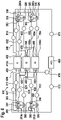
- Figure 4 to Figure 10 show several different electrical drive systems 400, 500, 600, 700, 800, 900, 1000 that each include a first predetermined number of thrust producing units and an electric power system with a second predetermined number of batteries.
- These electrical drive systems are given by way of example, different configurations of these electrical drive systems may be possible.
- Figure 4 shows an illustrative electrical drive system 400 for an electrically powered rotary-wing aircraft with a first predetermined number of thrust producing units and an electric power system 420.
- the electric power system 420 may include a second predetermined number of batteries.
- the first predetermined number may be greater than one.
- the second predetermined number may be greater than one.
- the first and second predetermined numbers may be equal to two.
- the electrically powered rotary-wing aircraft may include two thrust producing units 103a, 103b and an electric power system 420 with two batteries 410a, 410b.
- each one of the two thrust producing units 103a, 103b includes a rotor (e.g., rotor 331 of Figure 3 ) and an electrical drive unit 330 (e.g., electrical drive unit 330 of Figure 3 ).
- Each electrical drive unit 330 comprises at least two electric motors 380, 383 for driving the rotor.
- the electrical drive unit includes a first electric motor 380 and a second electric motor 383 for driving the rotor.
- the two batteries 410a, 410b may provide electric power to the at least two electric motors 380, 383 of the first and the second thrust producing units 103a, 103b.
- each battery of the two batteries 410a, 410b is coupled to at most one electric motor of the at least two electric motors 380, 383 of at least one of the two thrust producing units 103a, 103b, and each electric motor 380, 383 of the at least one of the two thrust producing units 103a, 103b is coupled to at most one of the two batteries 410a, 410b.
- the first battery 410a may be coupled to the first electric motor 380 of the first thrust producing unit 103a and to the first electric motor 380 of the second thrust producing unit 103b.
- the second battery 410b may be coupled to the second electric motor 383 of the first thrust producing unit 103a and to the second electric motor 383 of the second thrust producing unit 103b.
- each battery 410a, 410b is coupled to at most one electric motor of the at least two electric motors 380, 383 of the first thrust producing unit 103a, and each battery 410a, 410b is coupled to at most one electric motor of the at least two electric motors 380, 383 of the second thrust producing unit 103b.
- each electric motor 380, 383, of the first thrust producing unit 103a is coupled to a different battery 410a, 410b
- each electric motor 380, 383 of the second thrust producing unit 103b is coupled to a different battery 410a, 410b.
- the at least two electric motors 380, 383 of each one of the two thrust producing units 103a, 103b are coupled to different batteries of the two batteries 410a, 410b.
- the electric power system 420 may include a cable harness 340.
- the cable harness 340 may transmit electric power from the two batteries 410a, 410b to the at least two electric motors 380, 383 of the two thrust producing units 103a, 103b.
- cable harness 340 may include wires 441, 442, 443, 444 for transmitting electric power from the batteries 410a, 410b to the electric motors 380, 383 of thrust producing units 103a, 103b.
- wires 441 may transmit electric power from the first battery 410a to the first electric motor 380 of the first thrust producing unit 103a
- wires 442 may transmit electric power from the second battery 410b to the second electric motor 383 of the first thrust producing unit 103a
- wires 443 may transmit electric power from the first battery 410a to the first electric motor 380 of the second thrust producing unit 103b
- wires 444 may transmit electric power from the second battery 410b to the second electric motor 383 of the second thrust producing unit 103b.
- the electric power system 420 may include fuses 450 in connections between the second predetermined number of batteries 410a, 410b and the at least two electric motors 380, 383 of the first predetermined number of thrust producing units 103a, 103b.
- the fuses 450 may be adapted to protecting the second predetermined number of batteries 410a, 410b from high currents.
- a first fuse 450 may be coupled with wires 443 between the first battery 410a and the first electric motor 380 of the second thrust producing unit 103b.
- other fuses 450 may be coupled with wires 441, 442, and 444 between the respective battery and the respective electric motor, if desired.
- the electrically powered rotary-wing aircraft may comprise an automatic flight control system 460 that controls the first predetermined number of thrust producing unit 103a, 103b and the second predetermined number of batteries 410a, 410b.
- the electrically powered rotary-wing aircraft may comprise a battery control system 470 that is coupled to the automatic flight control system 460 and monitors a status of at least one battery of the second predetermined number of batteries 410a, 410b.
- the status may comprise at least one of a temperature, a charging level, an outgoing current, a consumption of energy, or a remaining time of operationality of the at least one battery of the second predetermined number of batteries 410a, 410b.
- a motor control system 471, 472 may be coupled to the automatic flight control system 460.
- the motor control system 471, 472 may control the functions and power needs of the at least two electric motors 380, 383.
- motor control system 471 may control the functions and power needs of the two electric motors 380, 383 of the first thrust producing unit 103a
- motor control system 472 may control the functions and power needs of the two electric motors 380, 383 of the second thrust producing unit 103b.
- a first subset of the first predetermined number of thrust producing units (e.g., first thrust producing unit 103a) is located on a portside (e.g., portside 104 of Figure 1 ) and a second subset of the first predetermined number of thrust producing units (e.g., second thrust producing unit 103b) is located on a starboard side (e.g., starboard side 105 of Figure 1 ) of the electrically powered rotary-wing aircraft.
- the motor control system 471, 472 may further comprise a right motor control system 471, and a left motor control system 472.
- the left motor control system 472 may control the functions and power needs of the at least two electric motors 380, 383 of the first subset of the first predetermined number of thrust producing units 103a located on the portside (e.g., portside 104 of Figure 1 ) and the right motor control system 471 may control the functions and power needs of the at least two electric motors 380, 383 of the second subset of the first predetermined number of thrust producing units 103b located on the starboard side (e.g., starboard side 105 of Figure 1 ) of the electrically powered rotary-wing aircraft.
- the remaining functioning battery 410b may provide sufficient electric power for a safe emergency landing of the electrically powered rotary-wing aircraft.
- the remaining functioning battery 410a may provide sufficient electric power for a safe emergency landing of the electrically powered rotary-wing aircraft 100.
- Figure 5 shows an illustrative electrical drive system 500 for an electrically powered rotary-wing aircraft (e.g., electrically powered rotary-wing aircraft 100 of Figure 1 or electrically powered rotary-wing aircraft 200 of Figure 2 ) with four thrust producing units 203a, 203b, 203h, 203c and an electric power system 520.
- the electric power system 520 may include two batteries 410a, 410b.
- the electrical drive system 500 comprises, in addition to the first and second thrust producing units 203a, 203b third and fourth thrust producing units 203h, 203c.
- the electrically powered rotary-wing aircraft comprises two pairs of thrust producing units 203a, 203b, 203h, 203c.
- the first and third thrust producing units 203a, 203h may be arranged on the portside (e.g., portside 104 of Figure 1 ) of the electrically powered rotary-wing aircraft, and the second and fourth thrust producing units 203b, 203c may be arranged on the starboard side (e.g., starboard side 105 of Figure 1 ) of the electrically powered rotary-wing aircraft.
- the portside e.g., portside 104 of Figure 1
- the second and fourth thrust producing units 203b, 203c may be arranged on the starboard side (e.g., starboard side 105 of Figure 1 ) of the electrically powered rotary-wing aircraft.
- All the thrust producing units comprise an electrical drive unit 330, comprising at least two motors 380, 383. As shown in Figure 5 , each thrust producing unit of the four thrust producing units 203a, 203b, 203h, 203c include first and second electric motors 380, 383.
- the first battery 410a may be coupled:
- the second battery 410b may be coupled:
- each battery of batteries 410a, 410b is coupled to four electric motors 380, 383 instead of being coupled to two electric motors as shown in Figure 4 .
- each battery of batteries 410a, 410b is coupled to at most one electric motor 380, 383 in any thrust producing unit of thrust producing units 203a, 203b, 203h, 203c.
- each electric motor 380, 383 of all thrust producing units 203a, 203b, 203h, 203c is connected to at most one of the two batteries 410a, 410b.
- no electric motor 380, 383 is coupled to more than one battery
- no battery 410a, 410b is coupled to more than one electric motor 380, 383 in any one of the thrust producing units 203a, 203b, 203h, 203c.
- the first electric motor 380 of all thrust producing units 203a, 203b, 203h, 203c ceases functioning, while the second battery 410b continues to provide power to the second electric motor 383 of thrust producing units 203a, 203b, 203h, 203c.
- the second battery 410b may provide sufficient electric power to the second electric motors 383 of the thrust producing units 203a, 203b, 203h, 203c to enable a safe emergency landing of the electrically powered rotary-wing aircraft.
- the second electric motor 383 of all thrust producing units 203a, 203b, 203h, 203c ceases functioning, while the first battery 410a continues to provide power to the first electric motor 380 of thrust producing units 203a, 203b, 203h, 203c.
- the first battery 410a may provide sufficient electric power to the first electric motors 380 of the thrust producing units 203a, 203b, 203h, 203c to enable a safe emergency landing of the electrically powered rotary-wing aircraft.
- Figure 6 shows an illustrative electrical drive system 600 for an electrically powered rotary-wing aircraft (e.g., electrically powered rotary-wing aircraft 100 of Figure 1 or electrically powered rotary-wing aircraft 200 of Figure 2 ) with four thrust producing units 203a, 203b, 203h, 203c and an electric power system 620.
- the electric power system 620 may include three batteries 410a, 410b, 610c.
- the electrical drive system 600 of Figure 6 comprises, in addition to the first and second batteries 410a, 410b a third battery 610c.
- the thrust producing units 203a, 203b, 203h, 203c each include an electrical drive unit 330 that has, in addition to the two electric motors 380, 383, at least one additional electric motor 386.
- the electric power system 620 may include fuses 450 in connections between the batteries 410a, 410b, 610c and the electric motors 380, 383, 386 of the four thrust producing units 203a, 203b, 203h, 203c.
- the fuses 450 may be adapted to protecting the batteries 410a, 410b, 610c from high currents.
- the electric power system 620 may include a cable harness 340.
- the cable harness 340 may transmit electric power from the three batteries 410a, 410b, 610c to the electric motors 380, 383, 386 of the four thrust producing units 203a, 203b, 203h, 203c.
- cable harness 340 may include wires 611, 612, 613, 614, 621, 622, 623, 624, 631, 632, 633, 634 for supplying electric power from the batteries 410a, 410b, 610c to the electric motors 380, 383, 386 of thrust producing units 203a, 203b, 203h, 203c.
- the first battery 410a is coupled:
- the second battery 410b is coupled:
- the third battery 610c is coupled:
- the first, second, and third electric motors 380, 383, 386 of each one of the first, second, third, and fourth thrust producing units 203a, 203b, 2033h, 203c are coupled to different batteries 410a, 410b, 610c.
- An electrically powered rotary-wing aircraft with an electrical drive system 600 as shown in Figure 6 that includes four thrust producing units 203a, 203b, 203h, 203c and three batteries 410a, 410b, 610c may provide a high safety level.
- the loss of one electric motor of the electric motors 380, 383, 386 in any one thrust producing unit may not be catastrophic as the remaining two operational electric motors of the electric motors 380, 383, 386 of the affected thrust producing unit continue to provide the required redundancy for operating the thrust producing unit.
- the remaining functioning batteries of the three batteries 410a, 410b, 610c may supply electric power to at least one electric motor of the at least two electric motors 380, 383 in each one of the first predetermined number of thrust producing units 203a, 203b, 203h, 203c in order to enable at least a safe flight of the electrically powered rotary-wing aircraft.
- the two remaining functioning batteries of the three batteries 410a, 410b, 610c may continue to provide power to two electric motors of the electric motors 380, 383, 386 in each thrust producing unit of thrust producing units 203a, 203b, 203h, 203c.
- the single battery supplies electric power to at least one electric motor of the three electric motors 380, 383, 386 in each one of the first predetermined number of thrust producing units 203a, 203b, 203c, 203d, 203e, 203f, 203g, 203h in order to enable at least a safe emergency landing of the electrically powered rotary-wing aircraft.
- Figure 7 shows an illustrative electrical drive system 700 for an electrically powered rotary-wing aircraft (e.g., electrically powered rotary-wing aircraft 100 of Figure 1 or electrically powered rotary-wing aircraft 200 of Figure 2 ) with six thrust producing units 203a, 203b, 203h, 203c, 203g, 203d and an electric power system 720.
- the electric power system 720 may include three batteries 410a, 410b, 610c.
- the electrical drive system 700 of Figure 7 comprises, in addition to the first, second, third, and fourth thrust producing units 203a, 203b, 203h, 203c a fifth and a sixth thrust producing unit 203g, 203d.
- Each one of the six thrust producing units 203a, 203b, 203h, 203c, 203g, 203d, may include a rotor and an electrical drive unit 330 with three electric motors 380, 383, 386.
- each battery 410a, 410b, 610c is coupled to six different electric motors 380, 383, 386.
- Figure 8 shows an illustrative electrical drive system 800 for an electrically powered rotary-wing aircraft (e.g., electrically powered rotary-wing aircraft 100 of Figure 1 or electrically powered rotary-wing aircraft 200 of Figure 2 ) with four thrust producing units 203a, 203b, 203h, 203c, each having an electrical drive unit 330 with two electric motors 380, 383, and an electric power system 820.
- the electric power system 820 may include four batteries 410a, 410b, 610c, 810d.
- the electrical drive system 800 of Figure 8 comprises, in addition to first and second batteries 410a, 410b, at least two additional batteries 610c, 810d.
- each battery of first, second, third, and fourth batteries 410a, 410b, 610c, 810d is coupled to two electric motors 380, 383 that are located in two different thrust producing units.
- the first battery 410a is coupled:
- the second battery 410b is coupled:
- the third battery 610c is coupled:
- the fourth battery 810d is coupled:
- the two electric motors 380, 383 of the first thrust producing unit 203a are coupled to the first and second batteries 410a, 410b
- the two electric motors 380, 383 of the second thrust producing unit 203b are coupled to the first and fourth batteries 410a, 810d
- the two electric motors 380, 383 of the third thrust producing unit 203h are coupled to the third and fourth batteries 610c, 810d
- the two electric motors 380, 383 of the fourth thrust producing unit 203c are coupled to the second and third batteries 410b, 610c.
- the two electric motors 380, 383 of any pair of the four thrust producing units 203a, 203b, 203h, 203c are coupled to a different subset of batteries of the four batteries 410a, 410b, 610c, 810d.
- the remaining functioning batteries of the four batteries 410a, 410b, 610c, 810d may supply electric power to at least one electric motor of the at least two electric motors 380, 383 in each one of the first predetermined number of thrust producing units 203a, 203b, 203h, 203c in order to enable at least a safe flight of the electrically powered rotary-wing aircraft.
- first electric motors 380 of the first and second thrust producing units 203a, 203b cease functioning, while the second electric motors 383 of the first and second thrust producing units 203a, 203b and both electric motors 380, 383 of the third and fourth thrust producing units 203h, 203c may continue to receive electric power from the remaining functioning batteries 410b, 610c, 810d.
- the remaining functioning batteries of the four batteries 410a, 410b, 610c, 810d may supply electric power to at least one electric motor of the at least two electric motors 380, 383 in at least three quarters of the first predetermined number of thrust producing units (i.e., three of the four thrust producing units) 203a, 203b, 203h, 203c.
- a safe flight of the electrically powered rotary-wing aircraft may be ensured with three quarters of the thrust producing units.
- both electric motors 380, 383 of the first thrust producing unit 203a may cease functioning, and the first electric motors 380 of the second and fourth thrust producing units 203b, 203c may cease functioning, while the second electric motor 383 of the second and fourth thrust producing units 203b, 203c and both electric motors 380, 383 of the third thrust producing unit 203h may continue to receive electric power from the remaining two functioning batteries 610c, 810d.
- the single battery supplies electric power to at least one electric motor of the two electric motors 380, 383 in two of the four thrust producing units 203a, 203b, 203h, 203c in order to enable at least a safe emergency landing of the electrically powered rotary-wing aircraft.
- both electric motors 380, 383 of the first and fourth thrust producing units 203a, 203c may cease functioning, and the first electric motors 380 of the second and fourth thrust producing units 203b, 203c may cease functioning, while the second electric motors 383 of the second and fourth thrust producing units 203b, 203c and both electric motors 380, 383 of the third thrust producing unit 203h may continue to receive electric power from the remaining two functioning batteries 610c, 810d.
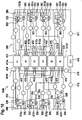
- Figure 9 shows an illustrative electrical drive system 900 for the electrically powered rotary-wing aircraft 200 of Figure 2 with eight thrust producing units and four batteries.
- the electrical drive system 900 comprises, in addition to the first, second, third, and fourth thrust producing units 203a, 203b, 203h, 203c, four additional thrust producing units 203g, 203d, 203f, 203e.
- Each one of the eight thrust producing units 203a, 203b, 203h, 203c, 203g, 203d, 203f, 203e may include a rotor (e.g., rotor 331 of Figure 3 ) and an electrical drive unit 330.
- Each electrical drive unit 330 may include two electric motors 380, 383.
- the electrical drive system 900 may include a cable harness 340 that transmits power from the four batteries 410a, 410b, 610c, 810d to the eight thrust producing units 203a, 203b, 203h, 203c, 203g, 203d, 203f, 203e.
- the portion of the cable harness 340 that couples first and second batteries 410a, 410b with first, second, third, and fourth thrust producing units 203a, 203b, 203h, 203c may be similar to the coupling of the first and second batteries 410a, 410b with first, second, third, and fourth thrust producing units 203a, 203b, 203h, 203c described with reference to electrical drive system 500 of Figure 5 .
- the first battery 410a may be coupled to the first electric motors 380 of the first, second, third, and fourth thrust producing unit 203a, 203b, 203h, 203c
- the second battery 410b may be coupled to the second electric motors 383 of the first, second, third, and fourth thrust producing unit 203a, 203b, 203h, 203c.
- the portion of the cable harness 340 that couples the third and fourth batteries 610c, 810d with fifth, sixth, seventh, and eighth thrust producing units 203g, 203d, 203f, 203e is similar to the couplings described with reference to the first and second batteries 410a, 410b with first, second, third, and fourth thrust producing units 203a, 203b, 203h, 203c.
- the third battery 610c may be coupled to the first electric motors 380 of the fifth, sixth, seventh, and eighth thrust producing unit 203g, 203d, 203f, 203e, and the second battery 410b may be coupled to the second electric motors 383 of the fifth, sixth, seventh, and eighth thrust producing unit 203g, 203d, 203f, 203e.
- Figure 10 shows an illustrative electrical drive system 1000 for the electrically powered rotary-wing aircraft 200 of Figure 2 , with a first predetermined number of eight thrust producing units 203a, 203b, 203h, 203c, 203g, 203f, 203d, 203e and a second predetermined number of six batteries 410a, 410b 610c, 810d, 1010e, 1010f.
- Each thrust producing unit of the eight thrust producing units 203a, 203b, 203h, 203c, 203g, 203f, 203d, 203e comprises a rotor and an electrical drive unit 330 with at least two electric motors. As shown in Figure 10 , each electrical drive unit 330 includes three electric motors 380, 383, 386.
- the second predetermined number of six batteries 410a, 410b 610c, 810d, 1010e, 1010f may provide electricity to the at least two electric motors 380, 383, 386 of the first predetermined number of eight thrust producing units 203a, 203b, 203h, 203c, 203g, 203f, 203d, 203e.
- each battery of the second predetermined number of batteries 410a, 410b, 610c, 810d, 1010e, 1010f is coupled to at most one electric motor of the at least two electric motors 380, 383, 386 of at least one of the first predetermined number of thrust producing units 203a, 203b, 203h, 203c, 203g, 203f, 203d, 203e.
- the three electric motors 380, 383, 386 of at least one thrust producing unit are coupled to different batteries.
- no battery of batteries 410a, 410b, 610c, 810d, 1010e, 1010f is coupled to more than one electric motor in any one of thrust producing units 203a, 203b, 203h, 203c, 203g, 203f, 203d, 203e.
- each electric motor 380, 383, 386 of the at least one of the eight thrust producing units 203a, 203b, 203h, 203c, 203g, 203f, 203d, 203e is coupled to at most one of the six of batteries 410a, 410b, 610c, 810d, 1010e, 1010f. As shown in Figure 10 , no electric motor 380, 383, 386 is coupled to more than one battery.
- the electric motors 380, 383, 386 of the first, second, and fifth thrust producing units 203a, 203b, 203g are coupled to the first, third, and fifth batteries 410a, 610c, 1010e, respectively
- the electric motors 380, 383, 386 of the third, fourth, and seventh thrust producing units 203h, 203c, 203f are coupled to the second, fourth, and sixth batteries 410b, 810d, 1010f, respectively
- the electric motors 380, 383, 386 of the sixth thrust producing unit 203d are coupled to the first, fourth, and fifth batteries 410a, 810d, 1010e, respectively
- the electric motors 380, 383, 386 of the eighth thrust producing unit 203e are coupled to the second, third, and sixth batteries 410b, 610c,1010f, respectively.
- the electric motors 380, 383, 386 of the first, second, and fifth thrust producing units 203a, 203b, 203g are coupled to a same subset of batteries (i.e., to first, third, and fifth battery), and the electric motors 380, 383, 386 of the third, fourth, and seventh thrust producing units 203h, 203c, 203f are coupled to a same subset of batteries (i.e., to second, fourth, and sixth battery).
- the three electric motors of any pair of the eight thrust producing units 203a, 203b, 203h, 203c, 203g, 203f, 203d, 203e may be coupled to a different subset of batteries of the six batteries 410a, 410b, 610c, 810d, 1010e, 1010f.
- the electric motors 380, 383, 386 of the first thrust producing unit 203a may be coupled to the first, third, and fifth batteries 410a, 610c, 1010e, respectively
- the electric motors 380, 383, 386 of the second thrust producing unit 203b may be coupled to the first, fourth, and fifth batteries 410a, 810d, 1010e, respectively
- the electric motors 380, 383, 386 of the third thrust producing unit 203h may be coupled to the first, third, and sixth batteries 410a, 610c, 1010f, respectively
- the electric motors 380, 383, 386 of the fourth thrust producing unit 203c may be coupled to the first, fourth, and sixth batteries 410a, 810d, 1010f, respectively
- the electric motors 380, 383, 386 of the fifth thrust producing unit 203g may be coupled to the second, third, and fifth batteries 410b, 610c, 1010e, respectively
- the three electric motors 380, 383, 386 of each one of the eight thrust producing units 203a, 203b, 203h, 203c, 203g, 203d, 203f, 203e is coupled to different batteries of the six batteries 410a, 410b, 610c, 810d, 1010e, 1010f.
- a cable harness 340 may transmit the electric power from the six batteries 410a, 410b, 610c, 810d, 1010e, 1010f to the three electric motors 380, 383, 386 of the eight thrust producing units 203a, 203b, 203h, 203c, 203g, 203d, 203f, 203e.
- connections between the six batteries 410a, 410b, 610c, 810d, 1010e, 1010f and the three electric motors 380, 383, 386 of the eight thrust producing units 203a, 203b, 203h, 203c, 203g, 203d, 203f, 203e may include fuses 450.
- the fuses 450 may be adapted to protecting the six batteries 410a, 410b, 610c, 810d, 1010e, 1010f from high currents.
- the electrically powered rotary-wing aircraft may include an automatic flight control system 460 that controls the eight thrust producing units 203a, 203b, 203h, 203c, 203g, 203d, 203f, 203e and the six batteries 410a, 410b, 610c, 810d, 1010e, 1010f.
- the electrical drive system 1000 may include a battery control system 470 that is coupled to the automatic flight control system 460 and monitors a status of at least one battery of the six batteries 410a, 410b, 610c, 810d, 1010e, 1010f. As shown in Figure 10 , the battery control system may monitor the status of all six batteries 410a, 410b, 610c, 810d, 1010e, 1010f.
- the status may include at least one of a temperature, a charging level, an outgoing current, a consumption of energy, or a remaining time of operationality of the at least one battery of the six batteries 410a, 410b, 610c, 810d, 1010e, 1010f.
- the battery control system 470 may be able to disconnect one or more of the six batteries 410a, 410b, 610c, 810d, 1010e, 1010f from one or more of the electric motors to which the battery is coupled under predefined conditions. As an example, the battery control system 470 may disconnect a battery from the respective electric motors if the temperature of the battery exceeds a predetermined threshold. As another example, the battery control system 470 may disconnect a battery from the respective electric motors if the charging level of the battery drops below a predetermined threshold.
- the electrical drive system 1000 may include a motor control system 471, 472 that is coupled to the automatic flight control system 460 and controls the functions and power needs of the three electric motors 380, 383, 386 of the eight thrust producing units 203a, 203b, 203h, 203c, 203g, 203d, 203f, 203e.
- the automatic flight control system 460 may receive status information about the six batteries 410a, 410b, 610c, 810d, 1010e, 1010f from the battery control system 470 and status information about the functions and power needs of the three electric motors 380, 383, 386 of the eight thrust producing units 203a, 203b, 203h, 203c, 203g, 203d, 203f, 203e from the motor control system 471, 472.
- the automatic flight control system 460 may direct the battery control system 470 to disconnect the one or more batteries and/or direct the motor control system 471, 472 to individually increase or decrease the output of one or more of the electric motors 380, 383, 386.
- a first subset of the eight thrust producing units may be located on a portside and a second subset of the eight thrust producing units (e.g., thrust producing units 203a, 203h, 203g, 203f) may be located on a starboard side of an electrically powered rotary-wing aircraft (e.g., as illustratively shown for electrically powered rotary-wing aircraft 200 of Figure 2 ).
- the motor control system 471, 472 may include a left motor control system 471 that controls the functions and power needs of the electric motors located on the portside of the electrically powered rotary-wing aircraft, and a right motor control system 472 that controls the functions and power needs of the electric motors located on the starboard side of the electrically powered rotary-wing aircraft.
- the remaining functioning three batteries of the six batteries 410a, 410b, 610c, 810d, 1010e, 1010f may supply electric power to at least one electric motor of the three electric motors 380, 383, 386 in at least seven of the eight thrust producing units 203a, 203b, 203h, 203c, 203g, 203d, 203f, 203e.
- the remaining functioning batteries may supply electric power to at least one electric motor in each one of the eight thrust producing units 203a, 203b, 203h, 203c, 203g, 203d, 203f, 203e.
- the remaining functioning batteries supply electric power to at least one electric motor in seven of the eight thrust producing units 203a, 203b, 203h, 203c, 203g, 203d, 203f, 203e, while all electric motors in only one of the eight thrust producing units 203a, 203b, 203h, 203c, 203g, 203d, 203f, 203e is without a power supply.
- the remaining functioning batteries of the six batteries 410a, 410b, 610c, 810d, 1010e, 1010f may supply electric power to at least one electric motor of the three electric motors 380, 383, 386 in each one of the eight thrust producing units 203a, 203b, 203h, 203c, 203g, 203d, 203f, 203e in order to enable at least a safe flight of the electrically powered rotary-wing aircraft.
- the first electric motor 380 of four of the eight thrust producing units 203a, 203b 203h, 203c, 203g, 203d, 203f, 203e may cease functioning, while the second and third electric motors 383, 386 of these four thrust producing units and the three electric motors 380, 383, 386 of the other four of the eight thrust producing units 203a, 203b 203h, 203c, 203g, 203d, 203f, 203e continue to receive electric power from the remaining functioning batteries.
- all eight thrust producing units 203a, 203b, 203h, 203c, 203g, 203d, 203f, 203e have at least two electric motors of the three electric motors 380, 383, 386 that receive electric power from functioning batteries.
- the single battery supplies electric power to at least one electric motor of the three electric motors 380, 383, 386 in four of the eight thrust producing units 203a, 203b, 203h, 203c 203g, 203d, 203f, 203e in order to enable at least a safe emergency landing of the electrically powered rotary-wing aircraft.
- all three electric motors 380, 383, 386 of thrust producing units 203g, 203d, 203f, 203e cease functioning, while the first motor 380 of thrust producing units 203a, 203b, 203h, 203c may continue to receive electric power from the remaining functioning battery 410a.
- Figure 4 to Figure 10 show several different electrical drive systems 400, 500, 600, 700, 800, 900, 1000 that each include an even number of thrust producing units.
- the electrical drive systems may include an odd number of thrust producing units instead.
- a subset with an odd number of these thrust producing units may be located on the longitudinal axis of the electrically powered rotary-wing aircraft (e.g., longitudinal axis 202 of electrically powered rotary-wing aircraft 200 of Figure 2 ).
- the remaining subset with an even number of these thrust producing units is divided in a first half that is located on the portside and a second half that is located on the starboard side of the electrically powered rotary wing aircraft.
- a different second predetermined number of batteries 410a, 410b, 610c, 810d, 1010e, 1010f may be selected.
- the second predetermined number of batteries may be selected between two and the total number of electric motors in the electrically powered rotary-wing aircraft.
- the selected number of batteries may be a trade-off between safety and additional weight during operation of the electrically powered rotary-wing aircraft. In fact, safety and weight may both increase with the number of batteries.
- the electrical drive unit 330 of Figure 3 is merely an example of an electrical drive unit with two or more electric motors.
- Other configurations of an electrical drive unit with redundant electric motors are known to the person skilled in the art. A more detailed discussion of such an electrical drive unit is therefore omitted for briefness and conciseness.
- wires of cable harness 340 of Figure 4 or Figure 6 are shown with a single connection between the batteries and the electric motors.
- wires 441 of Figure 4 are shown with a single line between first battery 410a and first electric motor 380 of first thrust producing unit 203a.
- all shown wires may include all the connectivity that is required to supply power from a battery to an electric motor.
- wires 441 of Figure 4 may include two wires if the first electric motor 380 is a DC motor: one wire between the positive terminal of the battery 410a and the electric motor 380 and another wire between the negative terminal of the battery 410a and the electric motor 380.
- the wires may include a switch to disconnect the battery from one or more electric motors.
- the battery control system 470 and/or the motor control system 471, 172 may control the switch.
- each thrust producing unit of Figure 4 to Figure 10 is shown to have either two or three electric motors. However, if desired, some thrust producing units may have two electric motors and other thrust producing units may have three electric motors. Some thrust producing units may have more than three electric motors, if desired. For example, some thrust producing units may have four electric motors.
- the cable harness 340 of Figure 8 to Figure 10 shows illustrative connections between the first predetermined number of thrust producing units and the second predetermined number of batteries.
- different connections between the first predetermined number of thrust producing units and the second predetermined number of batteries are possible as shown above with respect to the first and second configurations of the cable harness 340 of Figure 10 .
- Yet other configurations of the cable harness 340 of Figure 10 are possible and within the common knowledge of a person skilled in the art.
- the electric motors 380, 383, 386 of the first thrust producing unit 203a may be coupled to the first, second, and third batteries 410a, 410b, 610c, respectively
- the electric motors 380, 383, 386 of the second thrust producing unit 203b may be coupled to the first, second, and fourth batteries 410a, 410b, 810d, respectively
- the electric motors 380, 383, 386 of the third thrust producing unit 203h may be coupled to the first, second, and fifth batteries 410a, 410b, 1010e, respectively
- the electric motors 380, 383, 386 of the fourth thrust producing unit 203c may be coupled to the first, second, and sixth batteries 410a, 410b, 1010f, respectively
- the electric motors 380, 383, 386 of the fifth thrust producing unit 203g may be coupled to the first, third, and fourth batteries 410a, 610c, 810d, respectively
Abstract
Description
- The present embodiment relates to an electrically powered rotary-wing aircraft, and more particularly to an electrically powered rotary-wing aircraft with a first predetermined number of thrust producing units and a second predetermined number of batteries.
- Safety is absolutely paramount in air transportation. In fact, air transportation is a field that must typically consider strict applicable regulations, certification requirements, and safety demands independent of a selected air transportation vehicle, such as e. g. helicopters, airplanes, hybrid aircrafts, rockets and so on. Such regulations, certification requirements, and safety demands are e.g. specified by the US-American Federal Aviation Regulations (FAR) from the US-American Federal Aviation Administration (FAA), the European Certification Specifications (CS) from the European Aviation Safety Agency (EASA) and/or other aviation authorities.
- Fixed-wing aircrafts and rotary-wing aircrafts address these safety regulations in several different ways. The most common approach for fixed-wing aircrafts involves the use of overpowered jet engines so that the fixed-wing aircraft continues to be operational with the remaining operative jet engines when one jet engine fails.
- In contrast thereto, most rotary-wing aircrafts rely on the auto-rotation capability that most rotors provide and the use of two or more engines that are connected to a same rotor, whereby the rotor remains operational when one of the engines fails.
- Recently, urban air mobility (UAM) is emerging as a new market with new safety challenges. In particular, most current solutions for urban air mobility (UAM) involve vertical take-off and landing (VTOL) aircrafts with one or more thrust producing units that have an electrical drive unit and are usually equipped with fixed pitch propellers which do not have the auto-rotation capability of other rotary-wing aircrafts. Thus, the aviation manufacturers that produce VTOL aircrafts for the UAM market have to imagine new solutions to provide an extra layer of safety.
- The current state of the art at Electrified Vertical Take Off and Landing Vehicle (EVTOL) is that a direct drive electric motor is supplied with energy from batteries via a cable connection. In order to improve safety, the direct drive is connected with two energy sources, respectively batteries, using two cables. The uniform extraction of energy is ensured via diodes, relays, and bus-bars so that the same electric potential is always present on both connections.
- Document
WO 2019/232472 A1 relates to an electric power system and fault tolerant VTOL aircraft. The power system includes a reliability enhancing battery architecture for electric motors adapted for use in an aerial vehicle. Individual batteries may be used to power a subset of two or more motors in system with six or more motors. Each motor may be powered by two or more subsets of batteries, allowing accommodation for motor failure. With a failed motor in a vertical take-off or landing mode, power may be diverted to other motors to continue proper attitude control, and to provide sufficient thrust. With a failed motor a second motor offset from the failed motor may be powered down to facilitate attitude control. - This electric power system presented in document
WO 2019/232472 A1 ensures greater safety in the event of a battery failure. However, if a motor fails, there is no way to continue driving it and as a result all other motors have to compensate this loss. Otherwise, in the event of a battery failure, potential equalization must take place between the motors with only one source and the motors connected in parallel with two sources. However, such an electric power system requires the installation of diodes, relays and bus-bars and thus an increase in weight, cost and maintenance for all the electrical parts. - Many state-of-the-art electric power systems combine individual batteries and distribution of their electrical energy to the installed motors. Thereby, complex energy distribution boxes are needed, to ensure a redundant electrical energy distribution between the batteries in case of a battery failure. The more batteries are used, the more effort is required to connect and integrate them. Every single battery needs a distribution box to distribute and forward its electricity.
- It is, therefore, an objective to provide a new electrically powered rotary-wing aircraft that is suitable to overcome the above-described drawbacks.
- The new electrically powered rotary-wing aircraft should further provide a high safety level and ensure the continued supply of electric power to the thrust producing units. In particular, the loss of a battery should not impact the functioning of the thrust producing units.
- Moreover, the new electrically powered rotary-wing aircraft should include a simple electric power system (EPS) for providing electricity to the thrust producing units.
- The objective is solved by an electrically powered rotary-wing aircraft comprising the features of claim 1. More specifically, according to the present invention an electrically powered rotary-wing aircraft comprises a first predetermined number of thrust producing units and a second predetermined number of batteries. Each one of the first predetermined number of thrust producing units comprises a rotor, and an electrical drive unit with at least two electric motors for driving the rotor. The second predetermined number of batteries provides electricity to the at least two electric motors of the first predetermined number of thrust producing units. Each battery of the second predetermined number of batteries is coupled to at most one electric motor of the at least two electric motors of at least one of the first predetermined number of thrust producing units. Each electric motor of the at least one of the first predetermined number of thrust producing units is coupled to at most one of the second predetermined number of batteries.
- Thus, the number of batteries is distributed evenly between the electrical drive units in a meaningful and logical manner. More specifically, each electrical drive unit may be provided with two or more motors which are connected to different batteries. This means that each electric motor of each electrical drive unit is assigned to a battery and connected to this battery by a cable, resulting in a simple EPS architecture with a very high level of safety and significant savings in weight, number of parts, cost, and maintenance effort.
- The protection of a battery may be secured over an aviation-approved fuse. A battery balancing would be an additional possibility for an active power balancing of the electric motors. Equipotential bonding between the batteries is not required.
- More specifically, this EPS architecture was developed to ensure a high level of safety for an electrically powered rotary-wing aircraft, and particularly for the electrical drive unit of such an electrically powered rotary-wing aircraft. The EPS architecture is designed in such a way that an energy supply is always guaranteed, and no electrical drive unit will fail due to energy loss from one battery failure.
- Furthermore, the only components required for the architecture may be standard fuses and cables. More generally, fewer electrical components are required for the power distribution between the batteries. Nevertheless, some components such as diodes and relays are subject to a certain amount of wear and tear and have to be replaced on a regular basis. However, the fewer number of required components increases the time intervals between maintenance.
- Moreover, contrary to prior art solutions, the present EPS needs no distribution boxes, which are comparatively large and heavy. Thereby, the associated production and installation costs for the EPS may be reduced.
- According to one aspect, the first predetermined number is greater than one.
- According to one aspect, the second predetermined number is greater than one.
- According to one aspect, the at least two electric motors of each one of the first predetermined number of thrust producing units are coupled to different batteries of the second predetermined number of batteries.
- According to one aspect, the at least two electric motors of any pair of the first predetermined number of thrust producing units are coupled to a different subset of batteries of the second predetermined number of batteries.
- According to one aspect, the electrically powered rotary-wing aircraft further comprises a cable harness that transmits electric power from the second predetermined number of batteries to the at least two electric motors of the first predetermined number of thrust producing units.
- According to one aspect, the electrically powered rotary-wing aircraft further comprises fuses in connections between the second predetermined number of batteries and the at least two electric motors of the first predetermined number of thrust producing units.
- More specifically, only one fuse may be needed per connection.
- According to one aspect, the fuses are adapted to protecting the second predetermined number of batteries from high currents.
- More specifically, the batteries may be protected against voltage fluctuations and short-circuits.
- According to one aspect, the electrically powered rotary-wing aircraft further comprises an automatic flight control system that controls the first predetermined number of thrust producing units and the second predetermined number of batteries.
- According to one aspect, the electrically powered rotary-wing aircraft further comprises a battery control system that is coupled to the automatic flight control system and monitors a status of at least one battery of the second predetermined number of batteries.
- According to one aspect, the status comprises at least one of a temperature, a charging level, an outgoing current, a consumption of energy, or a remaining time of operationality of the at least one battery of the second predetermined number of batteries.
- According to one aspect, the electrically powered rotary-wing aircraft further comprises a motor control system that is coupled to the automatic flight control system and controls the functions and power needs of the at least two electric motors of the first predetermined number of thrust producing units.
- According to one aspect, a first subset of the first predetermined number of thrust producing units is located on a portside and a second subset of the first predetermined number of thrust producing units is located on a starboard side of the electrically powered rotary-wing aircraft. The motor control system further comprises a left motor control system that controls the functions and power needs of the at least two electric motors of the first subset of the first predetermined number of thrust producing units located on the portside of the electrically powered rotary-wing aircraft; and a right motor control system that controls the functions and power needs of the at least two electric motors of the second subset of the first predetermined number of thrust producing units located on the starboard side of the electrically powered rotary-wing aircraft.
- According to one aspect, in case of a failure of one of the second predetermined number of batteries, the remaining functioning batteries of the second predetermined number of batteries supply electric power to at least one electric motor of the at least two electric motors in each one of the first predetermined number of thrust producing units in order to enable at least a safe flight of the electrically powered rotary-wing aircraft.
- More specifically, the failure of a particular battery may not be a problem, as the remaining batteries continue to supply electric power to the thrust producing units.
- According to one aspect, in case of a failure of all but one of the second predetermined number of batteries, such that only a single battery of the second predetermined number of batteries remains functioning, the single battery supplies electric power to at least one electric motor of the at least two electric motors in at least half of the first predetermined number of thrust producing units in order to enable at least a safe emergency landing of the electrically powered rotary-wing aircraft.
- More specifically, in an emergency situation, for example in case of the loss of a battery or an electric motor, the automatic flight control system will manage the electric power needs to compensate the drop in performance to the remaining electric motors.
- Preferred embodiments are outlined by way of example in the following description with reference to the attached drawings. In these attached drawings, identical or identically functioning components and elements are labelled with identical reference numbers and characters and are, consequently, only described once in the following description.
-
Figure 1 is a diagram showing a front view of an illustrative electrically powered rotary-wing aircraft with at least two thrust producing units in accordance with some embodiments, -
Figure 2 is a diagram showing a top view of an illustrative electrically powered rotary-wing aircraft with at least eight thrust producing units in accordance with some embodiments, -
Figure 3 is a diagram of an illustrative thrust producing unit of the illustrative electrically powered rotary-wing aircraft ofFigure 1 orFigure 2 with at least two electric motors in accordance with some embodiments, -
Figure 4 is a diagram of an illustrative electrical drive system of an electrically powered rotary-wing aircraft with two thrust producing units and two batteries in accordance with some embodiments, -
Figure 5 is a diagram of an illustrative electrical drive system of an electrically powered rotary-wing aircraft with four thrust producing units and two batteries in accordance with some embodiments, -
Figure 6 is a diagram of an illustrative electrical drive system of an electrically powered rotary-wing aircraft with four thrust producing units and three batteries in accordance with some embodiments, -
Figure 7 is a diagram of an illustrative electrical drive system of an electrically powered rotary-wing aircraft with six thrust producing units and three batteries in accordance with some embodiments, -
Figure 8 is a diagram of an illustrative electrical drive system of an electrically powered rotary-wing aircraft with four thrust producing units and four batteries in accordance with some embodiments, -
Figure 9 is a diagram of an illustrative electrical drive system of an electrically powered rotary-wing aircraft with eight thrust producing units and four batteries in accordance with some embodiments, and -
Figure 10 is a diagram of an illustrative electrical drive system of an electrically powered rotary-wing aircraft with eight thrust producing units and six batteries in accordance with some embodiments. -
Figure 1 showsaircraft 100 andFigure 2 showsaircraft 200 that are both embodied by an electrically powered rotary-wing aircraft wing aircraft wing aircraft - The electrically powered rotary-
wing aircraft 100 ofFigure 1 is shown with avertical axis 106 that corresponds to the yaw axis inherent to the electrically powered rotary-wing aircraft 100. Thevertical axis 106 separates the electrically powered rotary-wing aircraft 100 into a portside 104 and astarboard side 105. - Electrically powered rotary-
wing aircraft 100 may have an aircraft airframe. The aircraft airframe defines a supporting structure ofaircraft 100 that is also referred to hereinafter as thefuselage 101 of the rotary-wing aircraft 100. The fuselage forms an aircraft interior region. The aircraft interior region preferably accommodates at least acabin 102 for passengers and/or cargo. - Illustratively, the electrically powered rotary-
wing aircraft 100 may include at least one upper wing and at least one lower wing. The at least one upper wing may be joined to the at least one lower wing in a joined-wing configuration. Illustratively, the upper and lower wing form aportside wing 107 assembly and astarboard side wing 108 assembly. - Alternatively, the electrically powered rotary-
wing aircraft 100 may comprises a singleportside wing 107 and a singlestarboard side wing 108. - By way of example, the electrically powered rotary-
wing aircraft 100 comprises a first predetermined number ofthrust producing units thrust producing units - Illustratively, a first
thrust producing unit 103a is arranged on theportside 104 of the electrically powered rotary-wing aircraft 100, and a secondthrust producing unit 103b is arranged on thestarboard side 105 of the electrically powered rotary-wing aircraft 100. - As an example, the first
thrust producing unit 103a is mounted on theportside wing 107, and the secondthrust producing unit 103b is mounted on thestarboard side wing 108. - Illustratively, each one of the first and second
thrust producing units - By way of example, the electrically powered rotary-
wing aircraft 100 may include an electric power system with a predetermined number of batteries for providing electricity to the at least two motors of the first and secondthrust producing units - Illustratively, each battery of the predetermined number of batteries may be coupled to at most one electric motor of the at least two electric motors of at least one of the first and second
thrust producing units thrust producing units - As an example, consider the scenario in which the electrically powered rotary-
wing aircraft 100 includes batteries X and Y. Consider further that the firstthrust producing unit 103a includes an electrical drive unit with electric motors A and B, the secondthrust producing unit 103b includes an electrical drive unit with electric motors C and D, that battery X is coupled to motors A and C, and that battery Y is coupled to motors B and D. - In this scenario, if both batteries X and Y are operational, then thrust producing
unit 103a remains operational in case of a failure of either one of electric motors A or B, and thrust producingunit 103b remains operational in case of a failure of either one of electric motors C or D. - Furthermore, if all electric motors A, B, C, and D are operational, then thrust producing
units unit 103a remains operational in case of a failure of battery X and electric motor A or in case of a failure of battery Y and electric motor B. Similarly, thrust producingunit 103b remains operational in case of a failure of battery X and electric motor C or in case of a failure of battery Y and electric motor D. -
Figure 2 shows a top view of an illustrative electrically powered rotary-wing aircraft 200. The electrically powered rotary-wing aircraft 200 is shown with mutuallyorthogonal axes -
Axis 202 represents alongitudinal axis 202 that corresponds to the roll axis inherent to the electrically powered rotary-wing aircraft 200. Thelongitudinal axis 202 separates the electrically powered rotary-wing aircraft 200 into a portside 104 and astarboard side 105.Axis 201 represents alateral axis 201 that corresponds to the pitch axis inherent to the electrically powered rotary-wing aircraft 200. - As shown in
Figure 2 , the electrically powered rotary-wing aircraft 200 includes eightthrust producing units wing aircraft 200 ofFigure 2 is eight. - As exemplarily illustrated, four
thrust producing units portside 104 of the electrically powered rotary-wing aircraft 200, and fourthrust producing units starboard side 105 of the electrically powered rotary-wing aircraft 200. - By way of example, three
thrust producing units portside wing 107, threethrust producing units starboard side wing 108, and twothrust producing units fuselage 101 of the electrical rotary-wing aircraft 200. - If desired, the first predetermined number of thrust producing units may be an even number. Illustratively, the arrangement of the
thrust producing units 203a to 203h may be symmetrical with respect to a vertical longitudinal median plane defined by the vertical axis (e.g.,vertical axis 106 ofFigure 1 ) and thelongitudinal axis 202 of the electrically powered rotary-wing aircraft 200. - Alternatively, the first predetermined number of thrust producing units may be an odd number. If desired, the odd number may be greater than one. Preferably, the arrangement of the thrust producing units between the portside 104 and the
starboard side 105 may be symmetrical with respect to a vertical longitudinal median plane defined by the vertical axis (e.g.,vertical axis 106 ofFigure 1 ) and thelongitudinal axis 202 of the electrically powered rotary-wing aircraft 200. Thus, at least one thrust producing unit of the thrust producing units may be arranged on the vertical longitudinal median plane defined by the vertical axis and thelongitudinal axis 202, while a first half of the remaining thrust producing units is arranged on the starboard side and a second half of the remaining thrust producing units is arranged on the portside of the electrically powered rotary-wing aircraft 200. -
Figure 3 shows a diagram of an illustrative thrust producing unit 300 (e.g., one ofthrust producing units Figure 1 or one ofthrust producing units Figure 2 ) of an the electrically powered rotary-wing aircraft (e.g., electrically powered rotary-wing aircraft 100 ofFigure 1 or electrically powered rotary-wing aircraft 200 ofFigure 2 ). Illustratively, thethrust producing unit 300 may include arotor 331 and anelectrical drive unit 330. - As shown in
Figure 3 ,rotor 331 may include at least two rotor blades. If desired, the number of rotor blades may be more than two. For example,rotor 331 may comprises three, four or more rotor blades. - Illustratively, the
electrical drive unit 330 includes at least two electric motors for driving therotor 331. As shown inFigure 3 , theelectrical drive unit 330 may include threeelectric motors electrical drive unit 330 may include more than three electric motors. -
Electric motors rotor 331. Illustratively,electric motors - Illustratively, the
thrust producing unit 300 may include an output shaft. The output shaft may couple the at least two electric motors to therotor 331. For example, three belts may couple the threeelectric motors - If desired, the
thrust producing unit 300 may have at least twoelectric motors unit electric motors - As an example, the
thrust producing unit electric motors - As exemplarily illustrated, a
cable harness 340 may transmit electric power from the batteries (e.g.,batteries Figure 6 ) to the at least twoelectric motors cable harness 340 may includewires wires 341 may couple a battery withelectric motor 380,wires 342 my couple a battery withelectric motor 383, andwires 343 may couple a battery withelectric motor 386. - It should be noted that the mechanism of the electrical drive unit is well-known to the person skilled in the art. Thus, a detailed description of such mechanism is omitted, for brevity and conciseness.
-
Figure 4 to Figure 10 show different illustrative electrical drive systems for an electrically powered rotary-wing aircraft (e.g., electrically powered rotary-wing aircraft 100 ofFigure 1 or electrically powered rotary-wing aircraft 200 ofFigure 2 ). - In particular,
Figure 4 to Figure 10 show several differentelectrical drive systems -
Figure 4 shows an illustrativeelectrical drive system 400 for an electrically powered rotary-wing aircraft with a first predetermined number of thrust producing units and anelectric power system 420. Theelectric power system 420 may include a second predetermined number of batteries. - Illustratively, the first predetermined number may be greater than one. If desired, the second predetermined number may be greater than one. As shown in
Figure 4 , the first and second predetermined numbers may be equal to two. Thus, the electrically powered rotary-wing aircraft may include twothrust producing units electric power system 420 with twobatteries - Illustratively, each one of the two
thrust producing units rotor 331 ofFigure 3 ) and an electrical drive unit 330 (e.g.,electrical drive unit 330 ofFigure 3 ). Eachelectrical drive unit 330 comprises at least twoelectric motors Figure 4 , the electrical drive unit includes a firstelectric motor 380 and a secondelectric motor 383 for driving the rotor. - The two
batteries electric motors thrust producing units - Illustratively, each battery of the two
batteries electric motors thrust producing units electric motor thrust producing units batteries - By way of example, the
first battery 410a may be coupled to the firstelectric motor 380 of the firstthrust producing unit 103a and to the firstelectric motor 380 of the secondthrust producing unit 103b. - Illustratively, the
second battery 410b may be coupled to the secondelectric motor 383 of the firstthrust producing unit 103a and to the secondelectric motor 383 of the secondthrust producing unit 103b. - Thus, each
battery electric motors thrust producing unit 103a, and eachbattery electric motors thrust producing unit 103b. - As exemplarily illustrated, each
electric motor thrust producing unit 103a is coupled to adifferent battery electric motor thrust producing unit 103b is coupled to adifferent battery Figure 4 , the at least twoelectric motors thrust producing units batteries - Illustratively, the
electric power system 420 may include acable harness 340. Thecable harness 340 may transmit electric power from the twobatteries electric motors thrust producing units - As shown in
Figure 4 ,cable harness 340 may includewires batteries electric motors thrust producing units wires 441 may transmit electric power from thefirst battery 410a to the firstelectric motor 380 of the firstthrust producing unit 103a,wires 442 may transmit electric power from thesecond battery 410b to the secondelectric motor 383 of the firstthrust producing unit 103a,wires 443 may transmit electric power from thefirst battery 410a to the firstelectric motor 380 of the secondthrust producing unit 103b, andwires 444 may transmit electric power from thesecond battery 410b to the secondelectric motor 383 of the secondthrust producing unit 103b. - By way of example, the
electric power system 420 may includefuses 450 in connections between the second predetermined number ofbatteries electric motors thrust producing units fuses 450 may be adapted to protecting the second predetermined number ofbatteries - As an example, a
first fuse 450 may be coupled withwires 443 between thefirst battery 410a and the firstelectric motor 380 of the secondthrust producing unit 103b. Similarly,other fuses 450 may be coupled withwires - Illustratively, the electrically powered rotary-wing aircraft (e.g., electrically powered rotary-
wing aircraft 100 ofFigure 1 or electrically powered rotary-wing aircraft 200 ofFigure 2 ) may comprise an automaticflight control system 460 that controls the first predetermined number ofthrust producing unit batteries - If desired, the electrically powered rotary-wing aircraft may comprise a
battery control system 470 that is coupled to the automaticflight control system 460 and monitors a status of at least one battery of the second predetermined number ofbatteries batteries - If desired, a
motor control system flight control system 460. As an example, themotor control system electric motors - As shown in
Figure 4 ,motor control system 471 may control the functions and power needs of the twoelectric motors thrust producing unit 103a, andmotor control system 472 may control the functions and power needs of the twoelectric motors thrust producing unit 103b. - Exemplarily, a first subset of the first predetermined number of thrust producing units (e.g., first
thrust producing unit 103a) is located on a portside (e.g.,portside 104 ofFigure 1 ) and a second subset of the first predetermined number of thrust producing units (e.g., secondthrust producing unit 103b) is located on a starboard side (e.g.,starboard side 105 ofFigure 1 ) of the electrically powered rotary-wing aircraft. - The
motor control system motor control system 471, and a leftmotor control system 472. The leftmotor control system 472 may control the functions and power needs of the at least twoelectric motors thrust producing units 103a located on the portside (e.g.,portside 104 ofFigure 1 ) and the rightmotor control system 471 may control the functions and power needs of the at least twoelectric motors thrust producing units 103b located on the starboard side (e.g.,starboard side 105 ofFigure 1 ) of the electrically powered rotary-wing aircraft. - By way of example, in case of a failure of the
first battery 410a, the remaining functioningbattery 410b may provide sufficient electric power for a safe emergency landing of the electrically powered rotary-wing aircraft. - Similarly, in case of a failure of, for example, the
second battery 410b, the remaining functioningbattery 410a may provide sufficient electric power for a safe emergency landing of the electrically powered rotary-wing aircraft 100. -
Figure 5 shows an illustrativeelectrical drive system 500 for an electrically powered rotary-wing aircraft (e.g., electrically powered rotary-wing aircraft 100 ofFigure 1 or electrically powered rotary-wing aircraft 200 ofFigure 2 ) with fourthrust producing units electric power system 520. Theelectric power system 520 may include twobatteries - In contrast to the
electrical drive system 400 ofFigure 4 , theelectrical drive system 500 comprises, in addition to the first and secondthrust producing units thrust producing units thrust producing units - Illustratively, the first and third
thrust producing units portside 104 ofFigure 1 ) of the electrically powered rotary-wing aircraft, and the second and fourththrust producing units starboard side 105 ofFigure 1 ) of the electrically powered rotary-wing aircraft. - All the thrust producing units comprise an
electrical drive unit 330, comprising at least twomotors Figure 5 , each thrust producing unit of the fourthrust producing units electric motors - Illustratively, the
first battery 410a may be coupled: - to the first
electric motor 380 of the firstthrust producing unit 203a, - to the first
electric motor 380 of the thirdthrust producing unit 203h, - to the first
electric motor 380 of the secondthrust producing unit 203b, and - to the first
electric motor 380 of the fourththrust producing unit 203c. - The
second battery 410b may be coupled: - to the second
electric motor 383 of the firstthrust producing unit 203a, - to the second
electric motor 383 of the thirdthrust producing unit 203h, - to the second
electric motor 383 of the secondthrust producing unit 203b, and - to the second
electric motor 383 of the fourththrust producing unit 203c. - Thus, each battery of
batteries electric motors Figure 4 . However, each battery ofbatteries electric motor thrust producing units electric motor thrust producing units batteries - In other words, no
electric motor battery electric motor thrust producing units - Thus, in the scenario in which the
first battery 410a fails, the firstelectric motor 380 of allthrust producing units second battery 410b continues to provide power to the secondelectric motor 383 ofthrust producing units second battery 410b may provide sufficient electric power to the secondelectric motors 383 of thethrust producing units - Similarly, in the scenario in which the
second battery 410b fails, the secondelectric motor 383 of allthrust producing units first battery 410a continues to provide power to the firstelectric motor 380 ofthrust producing units first battery 410a may provide sufficient electric power to the firstelectric motors 380 of thethrust producing units -
Figure 6 shows an illustrativeelectrical drive system 600 for an electrically powered rotary-wing aircraft (e.g., electrically powered rotary-wing aircraft 100 ofFigure 1 or electrically powered rotary-wing aircraft 200 ofFigure 2 ) with fourthrust producing units electric power system 620. Theelectric power system 620 may include threebatteries - In contrast to the
electrical drive system 500 ofFigure 5 , theelectrical drive system 600 ofFigure 6 comprises, in addition to the first andsecond batteries third battery 610c. Moreover, thethrust producing units electrical drive unit 330 that has, in addition to the twoelectric motors electric motor 386. - By way of example, the
electric power system 620 may includefuses 450 in connections between thebatteries electric motors thrust producing units fuses 450 may be adapted to protecting thebatteries - Illustratively, the
electric power system 620 may include acable harness 340. Thecable harness 340 may transmit electric power from the threebatteries electric motors thrust producing units - As shown in
Figure 6 ,cable harness 340 may includewires batteries electric motors thrust producing units - Illustratively, the
first battery 410a is coupled: - via
fuses 450 andwires 611 to the firstelectric motor 380 of the firstthrust producing unit 203a, - via
fuses 450 andwires 612 to the firstelectric motor 380 of the thirdthrust producing unit 203h, - via
fuses 450 andwires 613 to the firstelectric motor 380 of the secondthrust producing unit 203b, and - via
fuses 450 andwires 614 to the firstelectric motor 380 of the fourththrust producing unit 203c. - Illustratively, the
second battery 410b is coupled: - via
fuses 450 andwires 621 to the secondelectric motor 383 of the firstthrust producing unit 203a, - via
fuses 450 andwires 622 to the secondelectric motor 383 of the thirdthrust producing unit 203h, - via
fuses 450 andwires 623 to the secondelectric motor 383 of the secondthrust producing unit 203b, and - via
fuses 450 andwires 624 to the secondelectric motor 383 of the fourththrust producing unit 203c. - Illustratively, the
third battery 610c is coupled: - via
fuses 450 andwires 631 to the thirdelectric motor 386 of the firstthrust producing Unit 203a, - via
fuses 450 andwires 632 to the thirdelectric motor 386 of the thirdthrust producing unit 203h, - via
fuses 450 andwires 633 to the thirdelectric motor 386 of the secondthrust producing unit 203b, and - via
fuses 450 andwires 634 to the thirdelectric motor 386 of the fourththrust producing unit 203c. - As exemplarily illustrated, the first, second, and third
electric motors thrust producing units different batteries - An electrically powered rotary-wing aircraft with an
electrical drive system 600 as shown inFigure 6 that includes fourthrust producing units batteries electric motors electric motors - As another example, in case of a failure of one of the first, second, or
third battery batteries electric motors thrust producing units Figure 6 , the two remaining functioning batteries of the threebatteries electric motors thrust producing units - As yet another example, in case of a failure of all but one of the first, second, and
third batteries batteries electric motors thrust producing units -
Figure 7 shows an illustrativeelectrical drive system 700 for an electrically powered rotary-wing aircraft (e.g., electrically powered rotary-wing aircraft 100 ofFigure 1 or electrically powered rotary-wing aircraft 200 ofFigure 2 ) with sixthrust producing units electric power system 720. Theelectric power system 720 may include threebatteries - In contrast to the
electrical drive system 600 ofFigure 6 , theelectrical drive system 700 ofFigure 7 comprises, in addition to the first, second, third, and fourththrust producing units thrust producing unit thrust producing units electrical drive unit 330 with threeelectric motors - By way of example, each
battery electric motors - Illustratively, in addition to the coupling described in
Figure 6 : - the
first battery 410a is coupled to the firstelectric motor 380 of the fifththrust producing unit 203g, - the
first battery 410a is coupled to the firstelectric motor 380 of the sixththrust producing unit 203d, - the
second battery 410b is coupled to the secondelectric motor 383 of the fifththrust producing unit 203g, - the
second battery 410b is coupled to the secondelectric motor 383 of the sixththrust producing unit 203d, - the
third battery 610c is coupled to the thirdelectric motor 386 of the fifththrust producing unit 203g, and - the
third battery 610c is coupled to the thirdelectric motor 386 of the sixththrust producing unit 203d. -
Figure 8 shows an illustrativeelectrical drive system 800 for an electrically powered rotary-wing aircraft (e.g., electrically powered rotary-wing aircraft 100 ofFigure 1 or electrically powered rotary-wing aircraft 200 ofFigure 2 ) with fourthrust producing units electrical drive unit 330 with twoelectric motors electric power system 820. Theelectric power system 820 may include fourbatteries - In contrast to the
electrical drive system 500 ofFigure 5 , theelectrical drive system 800 ofFigure 8 comprises, in addition to first andsecond batteries additional batteries - By way of example, each battery of first, second, third, and
fourth batteries electric motors - Illustratively, the
first battery 410a is coupled: - to the first
electric motor 380 of the firstthrust producing unit 203a, and - to the first
electric motor 380 of the secondthrust producing unit 203b. - Illustratively, the
second battery 410b, is coupled: - to the
second motor 383 of the firstthrust producing unit 203a, and - to the first
electric motor 380 of the fourththrust producing unit 203c. - Illustratively, the
third battery 610c is coupled: - to the first
electric motor 380 of the thirdthrust producing unit 203h, and - to the second
electric motor 383 of the thirdthrust producing unit 203c. - Illustratively, the
fourth battery 810d is coupled: - to the second
electric motor 383 of the thirdthrust producing unit 203h, and - to the second
electric motor 383 of the secondthrust producing unit 203b. - Thus, the two
electric motors thrust producing unit 203a are coupled to the first andsecond batteries electric motors thrust producing unit 203b are coupled to the first andfourth batteries electric motors thrust producing unit 203h are coupled to the third andfourth batteries electric motors thrust producing unit 203c are coupled to the second andthird batteries electric motors thrust producing units batteries - In case of a failure of one of the four
batteries batteries electric motors thrust producing units first battery 410a, firstelectric motors 380 of the first and secondthrust producing units electric motors 383 of the first and secondthrust producing units electric motors thrust producing units batteries - Moreover, even in case of a failure of half of the second predetermined number of batteries (i.e., two of the four batteries) 410a, 410b, 610c, 810d, the remaining functioning batteries of the four
batteries electric motors - For example, in case of a failure of the first and
second batteries electric motors thrust producing unit 203a may cease functioning, and the firstelectric motors 380 of the second and fourththrust producing units electric motor 383 of the second and fourththrust producing units electric motors thrust producing unit 203h may continue to receive electric power from the remaining two functioningbatteries - Illustratively, in case of a failure of all but one of the four
batteries batteries electric motors thrust producing units - For example, in case of a failure of the first, second, and
third batteries electric motors thrust producing units electric motors 380 of the second and fourththrust producing units electric motors 383 of the second and fourththrust producing units electric motors thrust producing unit 203h may continue to receive electric power from the remaining two functioningbatteries -
Figure 9 shows an illustrativeelectrical drive system 900 for the electrically powered rotary-wing aircraft 200 ofFigure 2 with eight thrust producing units and four batteries. - In contrast to the
electrical drive system 800 ofFigure 8 , theelectrical drive system 900 comprises, in addition to the first, second, third, and fourththrust producing units thrust producing units thrust producing units rotor 331 ofFigure 3 ) and anelectrical drive unit 330. Eachelectrical drive unit 330 may include twoelectric motors - The
electrical drive system 900 may include acable harness 340 that transmits power from the fourbatteries thrust producing units - Illustratively, the portion of the
cable harness 340 that couples first andsecond batteries thrust producing units second batteries thrust producing units electrical drive system 500 ofFigure 5 . In particular, thefirst battery 410a may be coupled to the firstelectric motors 380 of the first, second, third, and fourththrust producing unit second battery 410b may be coupled to the secondelectric motors 383 of the first, second, third, and fourththrust producing unit - By way of example, the portion of the
cable harness 340 that couples the third andfourth batteries thrust producing units second batteries thrust producing units Figure 9 , thethird battery 610c may be coupled to the firstelectric motors 380 of the fifth, sixth, seventh, and eighththrust producing unit second battery 410b may be coupled to the secondelectric motors 383 of the fifth, sixth, seventh, and eighththrust producing unit -
Figure 10 shows an illustrativeelectrical drive system 1000 for the electrically powered rotary-wing aircraft 200 ofFigure 2 , with a first predetermined number of eightthrust producing units batteries - Each thrust producing unit of the eight
thrust producing units electrical drive unit 330 with at least two electric motors. As shown inFigure 10 , eachelectrical drive unit 330 includes threeelectric motors - The second predetermined number of six
batteries electric motors thrust producing units - Illustratively, each battery of the second predetermined number of
batteries electric motors thrust producing units electric motors Figure 10 , no battery ofbatteries thrust producing units - By way of example, each
electric motor thrust producing units batteries Figure 10 , noelectric motor - As shown in
Figure 10 , in a first configuration, theelectric motors thrust producing units fifth batteries electric motors thrust producing units sixth batteries electric motors thrust producing unit 203d are coupled to the first, fourth, andfifth batteries electric motors thrust producing unit 203e are coupled to the second, third, andsixth batteries - Thus, the
electric motors thrust producing units electric motors thrust producing units thrust producing units batteries - For example, in a second configuration, the electric motors 380, 383, 386 of the first thrust producing unit 203a may be coupled to the first, third, and fifth batteries 410a, 610c, 1010e, respectively, the electric motors 380, 383, 386 of the second thrust producing unit 203b may be coupled to the first, fourth, and fifth batteries 410a, 810d, 1010e, respectively, the electric motors 380, 383, 386 of the third thrust producing unit 203h may be coupled to the first, third, and sixth batteries 410a, 610c, 1010f, respectively, the electric motors 380, 383, 386 of the fourth thrust producing unit 203c may be coupled to the first, fourth, and sixth batteries 410a, 810d, 1010f, respectively, the electric motors 380, 383, 386 of the fifth thrust producing unit 203g may be coupled to the second, third, and fifth batteries 410b, 610c, 1010e, respectively, the electric motors 380, 383, 386 of the sixth thrust producing unit 203d may be coupled to the second, fourth, and fifth batteries 410b, 810d, 1010e, respectively, the electric motors 380, 383, 386 of the seventh thrust producing unit 203f may be coupled to the second, third, and sixth batteries 410b, 610c, 1010f, respectively, and the electric motors 380, 383, 386 of the eighth thrust producing unit 203e may be coupled to the second, fourth, and sixth batteries 410b, 810d, 1010f, respectively.
- In both, the first and second configurations, the three
electric motors thrust producing units batteries - As shown in
Figure 10 , acable harness 340 may transmit the electric power from the sixbatteries electric motors thrust producing units - Illustratively, the connections between the six
batteries electric motors thrust producing units fuses 450 may be adapted to protecting the sixbatteries - By way of example, the electrically powered rotary-wing aircraft may include an automatic
flight control system 460 that controls the eightthrust producing units batteries - Illustratively, the
electrical drive system 1000 may include abattery control system 470 that is coupled to the automaticflight control system 460 and monitors a status of at least one battery of the sixbatteries Figure 10 , the battery control system may monitor the status of all sixbatteries - The status may include at least one of a temperature, a charging level, an outgoing current, a consumption of energy, or a remaining time of operationality of the at least one battery of the six
batteries - If desired, the
battery control system 470 may be able to disconnect one or more of the sixbatteries battery control system 470 may disconnect a battery from the respective electric motors if the temperature of the battery exceeds a predetermined threshold. As another example, thebattery control system 470 may disconnect a battery from the respective electric motors if the charging level of the battery drops below a predetermined threshold. - Illustratively, the
electrical drive system 1000 may include amotor control system flight control system 460 and controls the functions and power needs of the threeelectric motors thrust producing units - The automatic
flight control system 460 may receive status information about the sixbatteries battery control system 470 and status information about the functions and power needs of the threeelectric motors thrust producing units motor control system flight control system 460 may direct thebattery control system 470 to disconnect the one or more batteries and/or direct themotor control system electric motors - If desired, a first subset of the eight thrust producing units (e.g., thrust producing
units units wing aircraft 200 ofFigure 2 ). - Illustratively, the
motor control system motor control system 471 that controls the functions and power needs of the electric motors located on the portside of the electrically powered rotary-wing aircraft, and a rightmotor control system 472 that controls the functions and power needs of the electric motors located on the starboard side of the electrically powered rotary-wing aircraft. - In the second configuration, in case of a failure of half of the second predetermined number of batteries (i.e., three of the six batteries) 410a, 410b, 610c, 810d, 1010e, 1010f the remaining functioning three batteries of the six
batteries electric motors thrust producing units - As an example, in case of a failure of the first, second, and
third batteries batteries batteries batteries batteries batteries batteries batteries thrust producing units - As another example, in case of a failure of the first, third, and
fifth batteries batteries batteries batteries batteries batteries batteries batteries thrust producing units thrust producing units - Illustratively, in the first and second configuration described above, in case of a failure of one of the six
batteries batteries electric motors thrust producing units - For example, in case of a failure of the
first battery 410a, the firstelectric motor 380 of four of the eightthrust producing units electric motors electric motors thrust producing units thrust producing units electric motors - Illustratively, in the first and second configuration described above, in case of a failure of all but one of the six
batteries batteries electric motors thrust producing units 203c - For example, in the first and second configuration described above, in case of a failure of all but the
first battery 410a (i.e., the second, third, fourth, fifth, andsixth battery electric motors thrust producing units first motor 380 ofthrust producing units battery 410a. - It should be noted that modifications to the above-described embodiments are within the common knowledge of the person skilled in the art and, thus, also considered as being part of the present invention.
- For instance,
Figure 4 to Figure 10 show several differentelectrical drive systems longitudinal axis 202 of electrically powered rotary-wing aircraft 200 ofFigure 2 ). Preferably, the remaining subset with an even number of these thrust producing units is divided in a first half that is located on the portside and a second half that is located on the starboard side of the electrically powered rotary wing aircraft. - Furthermore, a different second predetermined number of
batteries - Moreover, the
electrical drive unit 330 ofFigure 3 is merely an example of an electrical drive unit with two or more electric motors. Other configurations of an electrical drive unit with redundant electric motors are known to the person skilled in the art. A more detailed discussion of such an electrical drive unit is therefore omitted for briefness and conciseness. - In addition, the wires of
cable harness 340 ofFigure 4 orFigure 6 are shown with a single connection between the batteries and the electric motors. For example,wires 441 ofFigure 4 are shown with a single line betweenfirst battery 410a and firstelectric motor 380 of firstthrust producing unit 203a. However, all shown wires may include all the connectivity that is required to supply power from a battery to an electric motor. For example,wires 441 ofFigure 4 may include two wires if the firstelectric motor 380 is a DC motor: one wire between the positive terminal of thebattery 410a and theelectric motor 380 and another wire between the negative terminal of thebattery 410a and theelectric motor 380. If desired, the wires may include a switch to disconnect the battery from one or more electric motors. Thebattery control system 470 and/or themotor control system 471, 172 may control the switch. - Furthermore, each thrust producing unit of
Figure 4 to Figure 10 is shown to have either two or three electric motors. However, if desired, some thrust producing units may have two electric motors and other thrust producing units may have three electric motors. Some thrust producing units may have more than three electric motors, if desired. For example, some thrust producing units may have four electric motors. - Moreover, the
cable harness 340 ofFigure 8 to Figure 10 shows illustrative connections between the first predetermined number of thrust producing units and the second predetermined number of batteries. However, different connections between the first predetermined number of thrust producing units and the second predetermined number of batteries are possible as shown above with respect to the first and second configurations of thecable harness 340 ofFigure 10 . Yet other configurations of thecable harness 340 ofFigure 10 are possible and within the common knowledge of a person skilled in the art. For example, the electric motors 380, 383, 386 of the first thrust producing unit 203a may be coupled to the first, second, and third batteries 410a, 410b, 610c, respectively, the electric motors 380, 383, 386 of the second thrust producing unit 203b may be coupled to the first, second, and fourth batteries 410a, 410b, 810d, respectively, the electric motors 380, 383, 386 of the third thrust producing unit 203h may be coupled to the first, second, and fifth batteries 410a, 410b, 1010e, respectively, the electric motors 380, 383, 386 of the fourth thrust producing unit 203c may be coupled to the first, second, and sixth batteries 410a, 410b, 1010f, respectively, the electric motors 380, 383, 386 of the fifth thrust producing unit 203g may be coupled to the first, third, and fourth batteries 410a, 610c, 810d, respectively, the electric motors 380, 383, 386 of the sixth thrust producing unit 203d may be coupled to the second, third, and fourth batteries 410b, 610c, 810d, respectively, the electric motors 380, 383, 386 of the seventh thrust producing unit 203f may be coupled to the first, fifth, and sixth batteries 410a, 1010f, 1010e, respectively, and the electric motors 380, 383, 386 of the eighth thrust producing unit 203e may be coupled to the second, fifth, and sixth batteries 410b, 1010e, 1010f, respectively. -
- 100 aircraft
- 101 fuselage
- 102 cabin
- 103a first thrust producing unit
- 103b second thrust producing unit
- 104 portside
- 105 starboard side
- 106 vertical axis
- 107 portside wing
- 108 starboard side wing
- 200 rotary-wing aircraft
- 201 lateral axis
- 202 longitudinal axis
- 203a, 203b, 203c, 203d, 203e, 203f, 203g, 203h thrust producing unit
- 300 thrust producing unit
- 330 electrical drive unit
- 331 rotor
- 340 cable harness
- 341, 342, 343 wires
- 380 first electric motor
- 383 second electric motors
- 386 additional electric motor
- 400 electrical drive system
- 410a first battery
- 410b second battery
- 420 electric power system
- 441, 442, 443, 444 wires
- 450 fuse
- 460 automatic flight control system
- 470 battery control system
- 471 motor control system right
- 472 motor control system left
- 500 electrical drive system
- 520 electric power system
- 600 electrical drive system
- 610c battery
- 611, 612, 613, 614, 621, 622, 623, 624, 631, 632, 633, 634 wires
- 620 electric power system
- 700 electrical drive system
- 720 electric power system
- 800 electrical drive system
- 810d battery
- 820 electric power system
- 900 electrical drive system
- 920 electric power system
- 1000 electrical drive system
- 1010e, 1010f battery
- 1020 electric power system
Claims (15)
- An electrically powered rotary-wing aircraft (100) comprising:a first predetermined number of thrust producing units (103a, 103b), wherein each one of the first predetermined number of thrust producing units (103a, 103b) comprises:a rotor (331), andan electrical drive unit (330) with at least two electric motors (380, 383) for driving the rotor (331); anda second predetermined number of batteries (410a,410b) for providing electricity to the at least two electric motors (380, 383) of the first predetermined number of thrust producing units (103a, 103b);
characterized in thateach battery of the second predetermined number of batteries (410a,410b) is coupled to at most one electric motor of the at least two electric motors (380, 383) of at least one of the first predetermined number of thrust producing units (103a, 103b), and wherein each electric motor (380, 383) of the at least one of the first predetermined number of thrust producing units (103a, 103b) is coupled to at most one of the second predetermined number of batteries (410a,410b). - The electrically powered rotary-wing aircraft (100) of claim 1, wherein the first predetermined number is greater than one.
- The electrically powered rotary-wing aircraft (100) of any one of claims 1 or 2, wherein the second predetermined number is greater than one.
- The electrically powered rotary-wing aircraft (100) of any one of the preceding claims, wherein the at least two electric motors (380, 383) of each one of the first predetermined number of thrust producing units (103a, 103b) are coupled to different batteries of the second predetermined number of batteries (410a, 410b).
- The electrically powered rotary-wing aircraft (100) of any one of the preceding claims, wherein the at least two electric motors (380, 383) of any pair of the first predetermined number of thrust producing units (103a, 103b) are coupled to a different subset of batteries of the second predetermined number of batteries (410a, 410b).
- The electrically powered rotary-wing aircraft (100) of any one of the preceding claims, further comprising:
a cable harness (340) that transmits electric power from the second predetermined number of batteries (410a, 410b) to the at least two electric motors (380, 383) of the first predetermined number of thrust producing units (103a, 103b). - The electrically powered rotary-wing aircraft (100) of claim 6, further comprising:
fuses (450) in connections between the second predetermined number of batteries (410a, 410b) and the at least two electric motors (380, 383) of the first predetermined number of thrust producing units (103a, 103b). - The electrically powered rotary-wing aircraft (100) of claim 7, wherein the fuses (450) are adapted to protecting the second predetermined number of batteries (410a, 410b) from high currents.
- The electrically powered rotary-wing aircraft (100) of any one of the preceding claims, further comprising:
an automatic flight control system (460) that controls the first predetermined number of thrust producing units (103a, 103b) and the second predetermined number of batteries (410a, 410b). - The electrically powered rotary-wing aircraft (100) of claim 9, further comprising:
a battery control system (470) that is coupled to the automatic flight control system (460) and monitors a status of at least one battery of the second predetermined number of batteries (410a, 410b). - The electrically powered rotary-wing aircraft (100) of claim 10, wherein the status comprises at least one of a temperature, a charging level, an outgoing current, a consumption of energy, or a remaining time of operationality of the at least one battery of the second predetermined number of batteries (410a, 410b).
- The electrically powered rotary-wing aircraft (100) of any one of claims 9 to 11, further comprising:
a motor control system (471, 472) that is coupled to the automatic flight control system (460) and controls the functions and power needs of the at least two electric motors (380, 383) of the first predetermined number of thrust producing units (103a, 103b). - The electrically powered rotary-wing aircraft (100) of claim 11, wherein a first subset of the first predetermined number of thrust producing units (103a) is located on a portside (104) and a second subset of the first predetermined number of thrust producing units (103b) is located on a starboard side (105) of the electrically powered rotary-wing aircraft (100), and wherein the motor control system (471, 472) further comprises:a left motor control system (472) that controls the functions and power needs of the at least two electric motors (380, 383) of the first subset of the first predetermined number of thrust producing units (103a) located on the portside (104) of the electrically powered rotary-wing aircraft (100); anda right motor control system (471) that controls the functions and power needs of the at least two electric motors (380, 383) of the second subset of the first predetermined number of thrust producing units (103b) located on the starboard side (105) of the electrically powered rotary-wing aircraft (100).
- The electrically powered rotary-wing aircraft (100) of any one of the preceding claims, wherein in case of a failure of one of the second predetermined number of batteries (410a, 410b, 610c, 810d, 1010e, 1010f), the remaining functioning batteries of the second predetermined number of batteries (410a, 410b, 610c, 810d, 1010e, 1010f) supply electric power to at least one electric motor of the at least two electric motors (380, 383) in each one of the first predetermined number of thrust producing units (203a, 203b, 203c, 203d, 203e, 203f, 203g, 203h) in order to enable at least a safe flight of the electrically powered rotary-wing aircraft (100).
- The electrically powered rotary-wing aircraft (100) of any one of claims 1 to 13, wherein in case of a failure of all but one of the second predetermined number of batteries (410a, 410b, 610c, 810d, 1010e, 1010f), such that only a single battery of the second predetermined number of batteries (410a, 410b, 610c, 810d, 1010e, 1010f) remains functioning, the single battery supplies electric power to at least one electric motor of the at least two electric motors (380, 383) in at least half of the first predetermined number of thrust producing units (203a, 203b, 203c, 203d, 203e, 203f, 203g, 203h) in order to enable at least a safe emergency landing of the electrically powered rotary-wing aircraft (100).
Priority Applications (2)
| Application Number | Priority Date | Filing Date | Title |
|---|---|---|---|
| EP21400005.1A EP4049930B1 (en) | 2021-02-25 | 2021-02-25 | An electrically powered rotary-wing aircraft |
| US17/673,595 US20220267016A1 (en) | 2021-02-25 | 2022-02-16 | Electrically powered rotary-wing aircraft |
Applications Claiming Priority (1)
| Application Number | Priority Date | Filing Date | Title |
|---|---|---|---|
| EP21400005.1A EP4049930B1 (en) | 2021-02-25 | 2021-02-25 | An electrically powered rotary-wing aircraft |
Publications (2)
| Publication Number | Publication Date |
|---|---|
| EP4049930A1 true EP4049930A1 (en) | 2022-08-31 |
| EP4049930B1 EP4049930B1 (en) | 2023-12-06 |
Family
ID=75223306
Family Applications (1)
| Application Number | Title | Priority Date | Filing Date |
|---|---|---|---|
| EP21400005.1A Active EP4049930B1 (en) | 2021-02-25 | 2021-02-25 | An electrically powered rotary-wing aircraft |
Country Status (2)
| Country | Link |
|---|---|
| US (1) | US20220267016A1 (en) |
| EP (1) | EP4049930B1 (en) |
Citations (5)
| Publication number | Priority date | Publication date | Assignee | Title |
|---|---|---|---|---|
| WO2019232472A1 (en) | 2018-05-31 | 2019-12-05 | Joby Aero Inc. | Electric power system architecture and fault tolerant vtol aircraft using same |
| EP3702277A1 (en) * | 2019-02-27 | 2020-09-02 | AIRBUS HELICOPTERS DEUTSCHLAND GmbH | A multirotor aircraft that is adapted for vertical take-off and landing (vtol) |
| US20200283134A1 (en) * | 2015-12-21 | 2020-09-10 | Airbus Helicopters Deutschland GmbH | Multirotor electric aircraft with redundant security architecture |
| US20200298728A1 (en) * | 2018-01-25 | 2020-09-24 | H55 Sa | Construction and operation of electric or hybrid aircraft |
| EP3757014A1 (en) * | 2019-06-26 | 2020-12-30 | AIRBUS HELICOPTERS DEUTSCHLAND GmbH | A thrust producing unit with a fail-safe electrical drive unit |
-
2021
- 2021-02-25 EP EP21400005.1A patent/EP4049930B1/en active Active
-
2022
- 2022-02-16 US US17/673,595 patent/US20220267016A1/en active Pending
Patent Citations (5)
| Publication number | Priority date | Publication date | Assignee | Title |
|---|---|---|---|---|
| US20200283134A1 (en) * | 2015-12-21 | 2020-09-10 | Airbus Helicopters Deutschland GmbH | Multirotor electric aircraft with redundant security architecture |
| US20200298728A1 (en) * | 2018-01-25 | 2020-09-24 | H55 Sa | Construction and operation of electric or hybrid aircraft |
| WO2019232472A1 (en) | 2018-05-31 | 2019-12-05 | Joby Aero Inc. | Electric power system architecture and fault tolerant vtol aircraft using same |
| EP3702277A1 (en) * | 2019-02-27 | 2020-09-02 | AIRBUS HELICOPTERS DEUTSCHLAND GmbH | A multirotor aircraft that is adapted for vertical take-off and landing (vtol) |
| EP3757014A1 (en) * | 2019-06-26 | 2020-12-30 | AIRBUS HELICOPTERS DEUTSCHLAND GmbH | A thrust producing unit with a fail-safe electrical drive unit |
Also Published As
| Publication number | Publication date |
|---|---|
| EP4049930B1 (en) | 2023-12-06 |
| US20220267016A1 (en) | 2022-08-25 |
Similar Documents
| Publication | Publication Date | Title |
|---|---|---|
| US11198515B2 (en) | Method and system for distributed electrical loads connected to shared power sources | |
| EP3393904B1 (en) | Multirotor aircraft | |
| US11827347B2 (en) | Electric power system architecture and fault tolerant VTOL aircraft using same | |
| US7926763B2 (en) | Ice management system for rotary-wing aircraft | |
| US11661180B2 (en) | Systems and methods for power distribution in electric aircraft | |
| US11945594B2 (en) | Systems and methods for power distribution in electric aircraft | |
| CN111186585A (en) | Multi-battery-module electric airplane power system and electric airplane | |
| US11613368B2 (en) | Aircraft with electrical energy storage in nacelles | |
| US20240051672A1 (en) | Airship equipped with an electric distributed propulsion system | |
| EP4049930A1 (en) | An electrically powered rotary-wing aircraft | |
| WO2022180754A1 (en) | Aircraft and rotor blade module | |
| CN117184419A (en) | Aircraft with a plurality of aircraft seats |
Legal Events
| Date | Code | Title | Description |
|---|---|---|---|
| PUAI | Public reference made under article 153(3) epc to a published international application that has entered the european phase |
Free format text: ORIGINAL CODE: 0009012 |
|
| STAA | Information on the status of an ep patent application or granted ep patent |
Free format text: STATUS: THE APPLICATION HAS BEEN PUBLISHED |
|
| AK | Designated contracting states |
Kind code of ref document: A1 Designated state(s): AL AT BE BG CH CY CZ DE DK EE ES FI FR GB GR HR HU IE IS IT LI LT LU LV MC MK MT NL NO PL PT RO RS SE SI SK SM TR |
|
| STAA | Information on the status of an ep patent application or granted ep patent |
Free format text: STATUS: REQUEST FOR EXAMINATION WAS MADE |
|
| RAP1 | Party data changed (applicant data changed or rights of an application transferred) |
Owner name: AIRBUS URBAN MOBILITY GMBH |
|
| 17P | Request for examination filed |
Effective date: 20220909 |
|
| RBV | Designated contracting states (corrected) |
Designated state(s): AL AT BE BG CH CY CZ DE DK EE ES FI FR GB GR HR HU IE IS IT LI LT LU LV MC MK MT NL NO PL PT RO RS SE SI SK SM TR |
|
| P01 | Opt-out of the competence of the unified patent court (upc) registered |
Effective date: 20230530 |
|
| GRAP | Despatch of communication of intention to grant a patent |
Free format text: ORIGINAL CODE: EPIDOSNIGR1 |
|
| STAA | Information on the status of an ep patent application or granted ep patent |
Free format text: STATUS: GRANT OF PATENT IS INTENDED |
|
| RIC1 | Information provided on ipc code assigned before grant |
Ipc: B64D 27/24 20060101ALI20230901BHEP Ipc: B64C 29/00 20060101ALI20230901BHEP Ipc: B60L 50/60 20190101ALI20230901BHEP Ipc: H02J 1/08 20060101ALI20230901BHEP Ipc: H02J 7/00 20060101ALI20230901BHEP Ipc: B64C 27/08 20060101AFI20230901BHEP |
|
| INTG | Intention to grant announced |
Effective date: 20230922 |
|
| RIN1 | Information on inventor provided before grant (corrected) |
Inventor name: GEISS, MICHAEL Inventor name: PREISSER, GERO Inventor name: LANZENDOERFER, SILVIO |
|
| GRAS | Grant fee paid |
Free format text: ORIGINAL CODE: EPIDOSNIGR3 |
|
| GRAA | (expected) grant |
Free format text: ORIGINAL CODE: 0009210 |
|
| STAA | Information on the status of an ep patent application or granted ep patent |
Free format text: STATUS: THE PATENT HAS BEEN GRANTED |
|
| AK | Designated contracting states |
Kind code of ref document: B1 Designated state(s): AL AT BE BG CH CY CZ DE DK EE ES FI FR GB GR HR HU IE IS IT LI LT LU LV MC MK MT NL NO PL PT RO RS SE SI SK SM TR |
|
| REG | Reference to a national code |
Ref country code: GB Ref legal event code: FG4D |
|
| REG | Reference to a national code |
Ref country code: CH Ref legal event code: EP |
|
| REG | Reference to a national code |
Ref country code: DE Ref legal event code: R096 Ref document number: 602021007478 Country of ref document: DE |
|
| REG | Reference to a national code |
Ref country code: IE Ref legal event code: FG4D |
|
| REG | Reference to a national code |
Ref country code: LT Ref legal event code: MG9D |
|
| PG25 | Lapsed in a contracting state [announced via postgrant information from national office to epo] |
Ref country code: GR Free format text: LAPSE BECAUSE OF FAILURE TO SUBMIT A TRANSLATION OF THE DESCRIPTION OR TO PAY THE FEE WITHIN THE PRESCRIBED TIME-LIMIT Effective date: 20240307 |
|
| REG | Reference to a national code |
Ref country code: NL Ref legal event code: MP Effective date: 20231206 |
|
| PG25 | Lapsed in a contracting state [announced via postgrant information from national office to epo] |
Ref country code: LT Free format text: LAPSE BECAUSE OF FAILURE TO SUBMIT A TRANSLATION OF THE DESCRIPTION OR TO PAY THE FEE WITHIN THE PRESCRIBED TIME-LIMIT Effective date: 20231206 |