EP4039542A1 - Lighting control device and lighting control method for vehicular lamp, and vehicular lamp system - Google Patents
Lighting control device and lighting control method for vehicular lamp, and vehicular lamp system Download PDFInfo
- Publication number
- EP4039542A1 EP4039542A1 EP20872567.1A EP20872567A EP4039542A1 EP 4039542 A1 EP4039542 A1 EP 4039542A1 EP 20872567 A EP20872567 A EP 20872567A EP 4039542 A1 EP4039542 A1 EP 4039542A1
- Authority
- EP
- European Patent Office
- Prior art keywords
- light emitting
- luminance
- vehicular lamp
- emitting units
- lighting
- Prior art date
- Legal status (The legal status is an assumption and is not a legal conclusion. Google has not performed a legal analysis and makes no representation as to the accuracy of the status listed.)
- Granted
Links
Images



Classifications
-
- B—PERFORMING OPERATIONS; TRANSPORTING
- B60—VEHICLES IN GENERAL
- B60Q—ARRANGEMENT OF SIGNALLING OR LIGHTING DEVICES, THE MOUNTING OR SUPPORTING THEREOF OR CIRCUITS THEREFOR, FOR VEHICLES IN GENERAL
- B60Q1/00—Arrangement of optical signalling or lighting devices, the mounting or supporting thereof or circuits therefor
- B60Q1/26—Arrangement of optical signalling or lighting devices, the mounting or supporting thereof or circuits therefor the devices being primarily intended to indicate the vehicle, or parts thereof, or to give signals, to other traffic
- B60Q1/34—Arrangement of optical signalling or lighting devices, the mounting or supporting thereof or circuits therefor the devices being primarily intended to indicate the vehicle, or parts thereof, or to give signals, to other traffic for indicating change of drive direction
- B60Q1/38—Arrangement of optical signalling or lighting devices, the mounting or supporting thereof or circuits therefor the devices being primarily intended to indicate the vehicle, or parts thereof, or to give signals, to other traffic for indicating change of drive direction using immovably-mounted light sources, e.g. fixed flashing lamps
- B60Q1/381—Arrangement of optical signalling or lighting devices, the mounting or supporting thereof or circuits therefor the devices being primarily intended to indicate the vehicle, or parts thereof, or to give signals, to other traffic for indicating change of drive direction using immovably-mounted light sources, e.g. fixed flashing lamps with several light sources activated in sequence, e.g. to create a sweep effect
-
- B—PERFORMING OPERATIONS; TRANSPORTING
- B60—VEHICLES IN GENERAL
- B60Q—ARRANGEMENT OF SIGNALLING OR LIGHTING DEVICES, THE MOUNTING OR SUPPORTING THEREOF OR CIRCUITS THEREFOR, FOR VEHICLES IN GENERAL
- B60Q1/00—Arrangement of optical signalling or lighting devices, the mounting or supporting thereof or circuits therefor
- B60Q1/26—Arrangement of optical signalling or lighting devices, the mounting or supporting thereof or circuits therefor the devices being primarily intended to indicate the vehicle, or parts thereof, or to give signals, to other traffic
- B60Q1/34—Arrangement of optical signalling or lighting devices, the mounting or supporting thereof or circuits therefor the devices being primarily intended to indicate the vehicle, or parts thereof, or to give signals, to other traffic for indicating change of drive direction
- B60Q1/346—Arrangement of optical signalling or lighting devices, the mounting or supporting thereof or circuits therefor the devices being primarily intended to indicate the vehicle, or parts thereof, or to give signals, to other traffic for indicating change of drive direction with automatic actuation
-
- F—MECHANICAL ENGINEERING; LIGHTING; HEATING; WEAPONS; BLASTING
- F21—LIGHTING
- F21S—NON-PORTABLE LIGHTING DEVICES; SYSTEMS THEREOF; VEHICLE LIGHTING DEVICES SPECIALLY ADAPTED FOR VEHICLE EXTERIORS
- F21S41/00—Illuminating devices specially adapted for vehicle exteriors, e.g. headlamps
- F21S41/60—Illuminating devices specially adapted for vehicle exteriors, e.g. headlamps characterised by a variable light distribution
- F21S41/65—Illuminating devices specially adapted for vehicle exteriors, e.g. headlamps characterised by a variable light distribution by acting on light sources
- F21S41/663—Illuminating devices specially adapted for vehicle exteriors, e.g. headlamps characterised by a variable light distribution by acting on light sources by switching light sources
-
- H—ELECTRICITY
- H05—ELECTRIC TECHNIQUES NOT OTHERWISE PROVIDED FOR
- H05B—ELECTRIC HEATING; ELECTRIC LIGHT SOURCES NOT OTHERWISE PROVIDED FOR; CIRCUIT ARRANGEMENTS FOR ELECTRIC LIGHT SOURCES, IN GENERAL
- H05B45/00—Circuit arrangements for operating light-emitting diodes [LED]
- H05B45/10—Controlling the intensity of the light
-
- H—ELECTRICITY
- H05—ELECTRIC TECHNIQUES NOT OTHERWISE PROVIDED FOR
- H05B—ELECTRIC HEATING; ELECTRIC LIGHT SOURCES NOT OTHERWISE PROVIDED FOR; CIRCUIT ARRANGEMENTS FOR ELECTRIC LIGHT SOURCES, IN GENERAL
- H05B47/00—Circuit arrangements for operating light sources in general, i.e. where the type of light source is not relevant
- H05B47/10—Controlling the light source
- H05B47/155—Coordinated control of two or more light sources
-
- Y—GENERAL TAGGING OF NEW TECHNOLOGICAL DEVELOPMENTS; GENERAL TAGGING OF CROSS-SECTIONAL TECHNOLOGIES SPANNING OVER SEVERAL SECTIONS OF THE IPC; TECHNICAL SUBJECTS COVERED BY FORMER USPC CROSS-REFERENCE ART COLLECTIONS [XRACs] AND DIGESTS
- Y02—TECHNOLOGIES OR APPLICATIONS FOR MITIGATION OR ADAPTATION AGAINST CLIMATE CHANGE
- Y02B—CLIMATE CHANGE MITIGATION TECHNOLOGIES RELATED TO BUILDINGS, e.g. HOUSING, HOUSE APPLIANCES OR RELATED END-USER APPLICATIONS
- Y02B20/00—Energy efficient lighting technologies, e.g. halogen lamps or gas discharge lamps
- Y02B20/40—Control techniques providing energy savings, e.g. smart controller or presence detection
Definitions
- the present invention relates to a vehicular lamp system used as a turn lamp (direction indicator lamp), for example.
- a turn lamp used in a vehicle there is known a plurality of light emitting units which are sequentially lighted on with a time lag (refer to Patent Document 1, for example).
- a lighting method is called sequential blinking.
- a vehicular lamp which performs such sequential blinking is controlled so as to repeat an operation in which each light emitting unit is sequentially lighted on from the inner side to the outer side of the vehicle and then all the light emitting units are lighted off at the same time, for example.
- a vehicular lamp which performs sequential blinking gives a burden of recognizing lateral movement from the inner side to the outer side of the vehicle to a person who visually recognizes it (for example, a pedestrian or a driver of another vehicle) .
- a turn lamp which performs sequential blinking imposes a sense of discomfort as a direction indicator lamp.
- Patent Document 1 Japanese Unexamined Patent Application Publication No. 2015-145224
- Fig. 1 is a block diagram showing a configuration of a vehicular lamp system according to one embodiment.
- the illustrated vehicular lamp system is used as a direction indicator lamp (a turn lamp), and is configured to include a controller 1 and a pair of lamp units (vehicular lamps) 2L and 2R whose operation is controlled by the controller 1, for example.
- the controller 1 controls the lighting state of either the lamp unit 2L or 2R according to the turn signal, and instructs to irradiate light which indicates the vehicle travel direction.
- the pair of lamp units 2L and 2R are configured to include a drive circuit 20 and an LED array 21, respectively.
- the lamp unit 2L is installed on the left side of the front part of the vehicle.
- the lamp unit 2R is installed on the right side of the front part of the vehicle.
- a pair of lamp units may be installed on the left and right sides of the rear part of the vehicle.
- only a pair of lamp units 2L and 2R installed at the front of the vehicle will be considered.
- the drive circuit 20 provides drive power to each LED (light emitting element) included in the LED array 21, and lights on and off each LED.
- the LED array 21 has a plurality of LEDs, and each LED is made to emit light by the drive power provided from the drive circuit 20.
- Fig. 2 is a plan view showing an external configuration of the lamp unit. Although only the lamp unit 2L is shown here, the lamp unit 2R is bilaterally symmetrical and has the same configuration. As shown in the figure, the lamp unit 2L has a plurality of light emitting units 22 (nine in the illustrated example) arranged from the inner side (center side) of the vehicle to the outer side of the vehicle. Each light emitting unit 22 is associated with one or more LEDs included in the LED array 21, and can be individually lighted on and off by the control of the drive circuit 20, and its brightness (luminance) can be set freely. In the following, for convenience of explanation, it is assumed that one LED is associated with each light emitting unit 22.
- Fig. 3 is a diagram for explaining an operating state of the vehicular lamp system of the present embodiment.
- the operating state of the lamp units 2L and 2R are shown side by side, but at the time of actual operation, either one of the lamp units 2L or 2R operates according to the traveling direction to be indicated.
- the lamp unit 2L will be described, but note that the lamp unit 2R also operates in the same manner.
- each LED corresponding to each light emitting unit 22 is driven by a rated current, and from each light emitting unit 22, light with a first luminance is emitted.
- first luminance does not necessarily need be a constant value, and for example, luminance within an error range of about ⁇ 10% is allowable.
- the LED corresponding to the innermost light emitting unit 22 is temporarily driven with a current higher than the rated current, and this light emitting unit 22 emits light with a second luminance which is higher than the first luminance.
- a bright spot which is a region with a higher luminance than the other light emitting units 22 is formed at a position corresponding to one of the light emitting unit 22 at the innermost side of the vehicle.
- the drive current of the LED corresponding to the innermost light emitting unit 22 is returned to the rated current, and light is emitted with the first luminance from this light emitting unit 22.
- the second innermost light emitting unit 22 is temporarily driven with a current higher than the rated current, and light is emitted from the light emitting unit 22 with the second luminance which is higher than the first luminance.
- a bright spot which is a region with a higher luminance than the other light emitting units 22 is formed at a position corresponding to one of the light emitting unit 22 at the second innermost side of the vehicle.
- the light emitting unit 22 which is driven by a current higher than the rated current is sequentially switched.
- the bright spot formed by the emission of light with the second luminance moves sequentially from the inner side of the vehicle to the outer side of the vehicle.
- all light emitting units 22 are lighted off. After the light-off period has elapsed, the next cycle starts, and the operation at and after time t1 is repeated.
- Each light emitting unit 22 of the lamp unit 2L maintains a state of emitting light with the first luminance as a whole between time t1 and time t9.
- this state is referred to as a base lighting (state) .
- the bright spot is sequentially moved. For a certain period of time at or after time t10, all light emitting units 22 are lighted off.
- the lamp unit 2L repeatedly blinks (lights on and off) at a fixed interval as a whole, and operates so that the bright spot moves from the inner side of the vehicle to the outer side of the vehicle within the lighting period. That is, it is possible to realize a direction indicator display in which sequential blinking is superimposed on a conventional direction indicator with a simple blinking function.
- the lamp units 2L and 2R may be operated at the same time by the above-described control method.
- Figs. 4A to 4D are timing charts showing LED drive current waveforms corresponding to each light emitting unit of the lamp unit.
- the drive current for the lamp unit 2L will be described, but the same applies to the lamp unit 2R.
- Fig. 4A is a drive current waveform of the LED corresponding to the innermost light emitting unit 22.
- Fig. 4B is a drive current waveform of the LED corresponding to the second innermost light emitting unit 22.
- Fig. 4C is a drive current waveform of the LED corresponding to the third innermost light emitting unit 22.
- Fig. 4D is a drive current waveform of the LED corresponding to the outermost light emitting unit 22.
- the drive current of the LED corresponding to the innermost light emitting unit 22 is set higher than the rated current, and this state is maintained until time t2, after which the drive current is returned to the rated current.
- the light emitted from the region corresponding to the light emitting unit 22 becomes the second luminance and a bright spot is formed in this region (refer to Fig. 3 ).
- the drive current of the LEDs corresponding to the other light emitting units 22 are set to the rated current, the lights emitted from the regions corresponding to the other light emitting units 22 become the first luminance (base lighting state) .
- the drive current of the LED corresponding to the second innermost light emitting unit 22 is set higher than the rated current, and this state is maintained until time t3, after which the drive current is returned to the rated current.
- the light emitted from the region corresponding to the light emitting unit 22 becomes the second luminance and a bright spot is formed in this region (refer to Fig. 3 ).
- the drive current of the LEDs corresponding to the other light emitting units 22 are set to the rated current, the lights emitted from the regions corresponding to the other light emitting units 22 become the first luminance (base lighting state) .
- the drive current of the LED corresponding to the third innermost light emitting unit 22 is set higher than the rated current, and this state is maintained until time t4, after which the drive current is returned to the rated current.
- the light emitted from the region corresponding to the light emitting unit 22 becomes the second luminance and a bright spot is formed in this region (refer to Fig. 3 ).
- the drive current of the LEDs corresponding to the other light emitting units 22 are set to the rated current, the lights emitted from the regions corresponding to the other light emitting units 22 become the first luminance value (base lighting state) .
- the drive current is similarly provided at subsequent time periods. Further, as shown in Fig. 4D , at time t9, the drive current of the LED corresponding to the outermost light emitting unit 22 is set higher than the rated current, and this state is maintained until time t10, after which the drive current is returned to the rated current. As a result, during the period from time t9 to t10, the light emitted from the region corresponding to the light emitting unit 22 becomes the second luminance and a bright spot is formed in this region (refer to Fig. 3 ). At this time, as shown in Fig. 4A, Fig. 4B, and Fig. 4C , since the drive current of the LEDs corresponding to the other light emitting units 22 are set to the rated current, the lights emitted from the regions corresponding to the other light emitting units 22 become the first luminance (base lighting state) .
- the light-off period is set to the same length as the period from time t1 to time t10, for example.
- the length between a certain time (for example, time t1) and the next time (for example, time t2) is preferably set to about 50 ms, for example.
- the lighting period (between time t1 and t10) becomes 500 ms, and the light-off period also becomes 500 ms.
- the above values are merely an example.
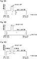
- Fig. 5A is a diagram for explaining a preferable luminance value of the bright spot.
- the vertical axis in the figure corresponds to luminance (cd/m 2 ), and the horizontal axis corresponds to the position in the vehicle width direction.
- the luminance (the first luminance) of the light emitting units 22 corresponding to each region in a base lighting state are defined as X
- the luminance (second luminance) of the light emitting unit 22 corresponding to the region which becomes the bright spot is defined as Y.
- Y is set to be greater than 1.2 times of X, more preferably set to be greater than 1.5 times of X, and further preferably set to be greater than 1.7 times of X.
- Fig. 5B is a diagram for explaining a preferable width value of the bright spot.
- the vertical axis in the figure corresponds to luminance (cd/m 2 ), and the horizontal axis corresponds to the position of the vehicle width direction.
- the width of each region in a base lighting state is defined as X
- the width of the region which becomes the bright spot is defined as Y.
- Y is set to be smaller than 1/2 of X, more preferably set to be smaller than 1/3 of X, and further preferably set to be smaller than 1/5 of X.
- Fig. 5C is a diagram for explaining a modified example of the bright spot.
- the vertical axis in the figure corresponds to luminance (cd/m 2 ), and the horizontal axis corresponds to the position of the vehicle width direction.
- dimming regions may be provided on both sides (or any one side) of the bright spot region with a luminance lower than the luminance of the light emitting regions which are in a base lighting state. In this case, the drive current in these regions may be set low.
- the light may either be lighted off or the luminance may only be lowered. By setting such dimming regions, the visibility of the bright spot can be further improved.
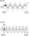
- Figs. 6A and 6B are diagrams for explaining a modified example of the lamp unit.
- each of the light emitting units 22 are not arranged in a line but are arranged in a zigzag manner.
- the bright spot also moves in a zigzag manner, but the bright spot moves from the inner side of the vehicle to the outer side of the vehicle as a whole.
- each first light emitting unit 22a constitutes a first optical system
- each second light emitting unit 22b constitutes a second optical system and are driven separately.
- each first light emitting unit 22a continues to irradiate light with the first luminance
- each second light emitting unit 22b is sequentially lighted on.
- each light emitting unit may be arranged from the lower side of the vehicle toward the upper side of the vehicle, or may be arranged in an oblique direction, or may be arranged in combination of a plurality of arranging directions.
- the bright spot can be moved from the lower side of the vehicle to the upper side of the vehicle, or the bright spot can be moved in an oblique direction, or the bright spot can be moved in combination of a plurality of arranging directions.
- the shape and area of each light emitting unit do not necessarily have to be the same.
- the movement of the bright spot is a so-called apparent movement, it is possible to further increase awareness and conspicuity toward the direction indicator display without raising the luminance too high with respect to the regions in a base lighting state. That is, visibility of the luminance can be improved without increasing the drive current too much. Furthermore, by moving the bright spot, it is possible to increase the momentary awareness from all viewing angles and realize a new appearance with a good impression.
- the whole lamp including each light emitting unit is recognized as one group. This stems from the law of common fate in Gestalt psychology. Since the bright spot is moved (apparent movement) within the region recognized as one group, the movement of the bright spot does not interfere with the recognition of blinking of the whole group.
- the present invention is not limited to the contents of the above-described embodiments, and can be variously modified and implemented within the scope of the gist of the present invention.
- rise timing of the base lighting state and rise timing of the first bright spot are set at the same timing, but the two may be set to be different.
- fall timing of the base lighting state and fall timing of the last bright spot are set at the same timing, but the two may be set to be different.
- the repeating cycle of the bright spot movement and the repeating cycle of the base lighting state do not have to be the same.
- the moving speed of the bright spot does not have to be constant, and may be gradually increased, or may be gradually decreased, or may be irregularly changed, for example.
- the number of the bright spot formed at a certain time is not limited to one, and two or more bright spots may be formed and moved at the same time.
- the area and shape of the bright spot do not have to be constant, and the area may be gradually increased or the area may be gradually decreased, or the area and/or the shape may be changed irregularly, for example.
- Fig. 7 is a diagram for explaining an operating state of a modified example of the vehicular lamp system.
- the operating state of the lamp units 2L and 2R are shown side by side, but at the time of actual operation, either one of the lamp units 2L or 2R operates according to the traveling direction to be indicated.
- a dark spot region of the third luminance which is lower than the first luminance is controlled so as to move sequentially with lapse of time.
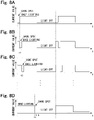
- Figs. 8A to 8D are timing charts showing LED drive current waveforms corresponding to each light emitting unit of the lamp unit in the modified example in which the dark spot is moved.
- the drive current for the lamp unit 2L will be described, but the same applies to the lamp unit 2R.
- Fig. 8A is a drive current waveform of the LED corresponding to the innermost light emitting unit 22.
- Fig. 8B is a drive current waveform of the LED corresponding to the second innermost light emitting unit 22 .
- Fig. 8C is a drive current waveform of the LED corresponding to the third innermost light emitting unit 22.
- Fig. 8D is a drive current waveform of the LED corresponding to the outermost light emitting unit 22.
- the drive current has been set to be greater than the rated current, whereas, in the case of the dark spot, the drive current is temporarily set to be smaller than the rated current.
- the drive current of the dark spot has the same magnitude as when the light is off, but the magnitude of the drive current of the two may be different.
- the luminance of the regions on both sides (or one side) of the dark spot may be set to be relatively greater. Thereby, the visibility of the dark spot can be further improved.
Landscapes
- Engineering & Computer Science (AREA)
- Mechanical Engineering (AREA)
- General Engineering & Computer Science (AREA)
- Lighting Device Outwards From Vehicle And Optical Signal (AREA)
Abstract
Description
- The present invention relates to a vehicular lamp system used as a turn lamp (direction indicator lamp), for example.
- As a type of a turn lamp used in a vehicle, there is known a plurality of light emitting units which are sequentially lighted on with a time lag (refer to
Patent Document 1, for example). Here, such a lighting method is called sequential blinking. A vehicular lamp which performs such sequential blinking is controlled so as to repeat an operation in which each light emitting unit is sequentially lighted on from the inner side to the outer side of the vehicle and then all the light emitting units are lighted off at the same time, for example. - In a vehicular lamp which performs sequential blinking as described above, it gives a burden of recognizing lateral movement from the inner side to the outer side of the vehicle to a person who visually recognizes it (for example, a pedestrian or a driver of another vehicle) . Thus, compared to a conventional turn lamp which simply repeats blinking, there is a possibility that a turn lamp which performs sequential blinking imposes a sense of discomfort as a direction indicator lamp.
- Patent Document 1:
Japanese Unexamined Patent Application Publication No. 2015-145224 - In a specific aspect, it is an object of the present invention to provide a technique capable of reducing a sense of discomfort during sequential blinking.
- (1) A lighting controller for a vehicular lamp according to one aspect of the present invention is (a) a lighting controller for a vehicular lamp to control lighting of the vehicular lamp, (b) where the lighting controller is configured to control so that a light emitting region of the vehicular lamp is repeatedly lighted on and off with a first luminance, and where, during the time when the light emitting region is lighted on, at a partial region of the light emitting region, one or more bright spots are set with a second luminance that is higher than the first luminance to be moved within the light emitting region, or during the time when the light emitting region is lighted on, at the partial region of the first light emitting region, one or more dark spots are set with a third luminance that is lower than the first luminance to be moved within the light emitting region.
- (2) A lighting controller for a vehicular lamp according to one aspect of the present invention is (a) a lighting controller for a vehicular lamp having a plurality of light emitting units to control lighting of the vehicular lamp, (b) where the lighting controller is configured to control so that the plurality of light emitting units is repeatedly lighted on and off with a first luminance, and (c) where, within the time period in which the plurality of light emitting units is lighted on, one or more bright spots are temporarily set with a second luminance that is higher than the first luminance to at least one light emitting unit among the plurality of light emitting units to be moved in a predetermined direction, or one or more dark spots are temporarily set with a third luminance that is lower than the first luminance to at least one light emitting unit among the plurality of light emitting units to be moved in a predetermined direction.
- (3) A lighting controller for a vehicular lamp according to one aspect of the present invention is (a) a lighting controller for a vehicular lamp having a plurality of first light emitting units and a plurality of second light emitting units each of which is intermittently arranged between the first light emitting units, to control lighting of the vehicular lamp, (b) where the lighting controller is configured to control so that the plurality of first light emitting units is repeatedly lighted on and off with a first luminance, and (c) where, within the time period in which the plurality of first light emitting units is lighted on, one or more bright spots are temporarily set with a second luminance that is higher than the first luminance to at least one of the second light emitting units among the plurality of second light emitting units to be moved in a predetermined direction, or one or more dark spots are temporarily set with a third luminance that is lower than the first luminance to at least one of the second light emitting units among the plurality of second light emitting units to be moved in a predetermined direction.
- (4) A lighting control method for a vehicular lamp according to one aspect of the present invention is (a) a lighting control method for a vehicular lamp to control lighting of the vehicular lamp, (b) where the lighting control method is configured to control so that a light emitting region of the vehicular lamp is repeatedly lighted on and off with a first luminance, and where, during the time when the light emitting region is lighted on, at a partial region of the light emitting region, one or more bright spots are set with a second luminance that is higher than the first luminance to be moved within the light emitting region, or during the time when the light emitting region is lighted on, at the partial region of the light emitting region, one or more dark spots are set with a third luminance that is lower than the first luminance to be moved within the light emitting region.
- (5) A lighting control method for a vehicular lamp according to one aspect of the present invention is (a) a lighting control method for a vehicular lamp having a plurality of light emitting units to control lighting of the vehicular lamp, (b) where the lighting control method is configured to control so that the plurality of light emitting units is repeatedly lighted on and off with a first luminance, and (c) where, within the time period in which the plurality of light emitting units is lighted on, one or more bright spots are temporarily set with a second luminance that is higher than the first luminance to at least one light emitting unit among the plurality of light emitting units to be moved in a predetermined direction, or one or more dark spots are temporarily set with a third luminance that is lower than the first luminance to at least one light emitting unit among the plurality of light emitting units to be moved in a predetermined direction.
- (6) A lighting control method for a vehicular lamp according to one aspect of the present invention is (a) a lighting control method for a vehicular lamp having a plurality of first light emitting units and a plurality of second light emitting units each of which is intermittently arranged between the first light emitting units, to control lighting of the vehicular lamp, (b) where the lighting control method is configured to control so that the plurality of first light emitting units is repeatedly lighted on and off with a first luminance, and (c) where, within the time period in which the plurality of first light emitting units is lighted on, one or more bright spots are temporarily set with a second luminance that is higher than the first luminance to at least one of the second light emitting units among the plurality of second light emitting units to be moved in a predetermined direction, or one or more dark spots are temporarily set with a third luminance that is lower than the first luminance to at least one of the second light emitting units among the plurality of second light emitting units to be moved in a predetermined direction.
- (7) A vehicular lamp system according to one aspect of the present invention is a vehicular lamp system including any one of the lighting controller described above and a vehicular lamp controlled by the lighting controller.
- According to the above configurations, a sense of discomfort during sequential blinking can be reduced.
-
-
Fig. 1 is a block diagram showing a configuration of a vehicular lamp system according to one embodiment. -
Fig. 2 is a plan view showing an external configuration of the lamp unit. -
Fig. 3 is a diagram for explaining an operating state of the vehicular lamp system of the present embodiment. -
Figs. 4A to 4D are timing charts showing LED drive current waveforms corresponding to each light emitting unit of the lamp unit. -
Fig. 5A is a diagram for explaining a preferable luminance value of the bright spot.Fig. 5B is a diagram for explaining a preferable width value of the bright spot.Fig. 5C is a diagram for explaining a modified example of the bright spot. -
Figs. 6A and 6B are diagrams for explaining a modified example of the lamp unit. -
Fig. 7 is a diagram for explaining an operating state of a modified example of the vehicular lamp system. -
Figs. 8A to 8D are timing charts showing LED drive current waveforms corresponding to each light emitting unit of the lamp unit in the modified example in which the dark spot is moved. -
Fig. 1 is a block diagram showing a configuration of a vehicular lamp system according to one embodiment. The illustrated vehicular lamp system is used as a direction indicator lamp (a turn lamp), and is configured to include acontroller 1 and a pair of lamp units (vehicular lamps) 2L and 2R whose operation is controlled by thecontroller 1, for example. - When a turn signal which indicates that the direction indicator has been operated is being input from the vehicle, the
controller 1 controls the lighting state of either thelamp unit - The pair of
lamp units drive circuit 20 and anLED array 21, respectively. Thelamp unit 2L is installed on the left side of the front part of the vehicle. Thelamp unit 2R is installed on the right side of the front part of the vehicle. Similarly, a pair of lamp units may be installed on the left and right sides of the rear part of the vehicle. For the sake of simplicity, in the present embodiment, only a pair oflamp units - The
drive circuit 20 provides drive power to each LED (light emitting element) included in theLED array 21, and lights on and off each LED. - The
LED array 21 has a plurality of LEDs, and each LED is made to emit light by the drive power provided from thedrive circuit 20. -
Fig. 2 is a plan view showing an external configuration of the lamp unit. Although only thelamp unit 2L is shown here, thelamp unit 2R is bilaterally symmetrical and has the same configuration. As shown in the figure, thelamp unit 2L has a plurality of light emitting units 22 (nine in the illustrated example) arranged from the inner side (center side) of the vehicle to the outer side of the vehicle. Eachlight emitting unit 22 is associated with one or more LEDs included in theLED array 21, and can be individually lighted on and off by the control of thedrive circuit 20, and its brightness (luminance) can be set freely. In the following, for convenience of explanation, it is assumed that one LED is associated with eachlight emitting unit 22. -
Fig. 3 is a diagram for explaining an operating state of the vehicular lamp system of the present embodiment. Here, the operating state of thelamp units lamp units lamp unit 2L will be described, but note that thelamp unit 2R also operates in the same manner. - When the turn signal is input, at time t1, except for one of the
light emitting unit 22 of thelamp unit 2L at the inner side of the vehicle, each LED corresponding to eachlight emitting unit 22 is driven by a rated current, and from eachlight emitting unit 22, light with a first luminance is emitted. Here, since the luminance of the corresponding LED in eachlight emitting unit 22 may vary, the above-described "first luminance" does not necessarily need be a constant value, and for example, luminance within an error range of about ± 10% is allowable. - At the above-described time t1, the LED corresponding to the innermost
light emitting unit 22 is temporarily driven with a current higher than the rated current, and thislight emitting unit 22 emits light with a second luminance which is higher than the first luminance. As a result, a bright spot which is a region with a higher luminance than the otherlight emitting units 22 is formed at a position corresponding to one of thelight emitting unit 22 at the innermost side of the vehicle. - At the next time t2, the drive current of the LED corresponding to the innermost
light emitting unit 22 is returned to the rated current, and light is emitted with the first luminance from thislight emitting unit 22. Further, at this time t2, the second innermostlight emitting unit 22 is temporarily driven with a current higher than the rated current, and light is emitted from thelight emitting unit 22 with the second luminance which is higher than the first luminance. As a result, a bright spot which is a region with a higher luminance than the otherlight emitting units 22 is formed at a position corresponding to one of thelight emitting unit 22 at the second innermost side of the vehicle. - Similarly, at time t3, t4, ..., t9, the
light emitting unit 22 which is driven by a current higher than the rated current is sequentially switched. As a result, as shown in the figure, the bright spot formed by the emission of light with the second luminance moves sequentially from the inner side of the vehicle to the outer side of the vehicle. After that, for a certain period of time at or after time t10, alllight emitting units 22 are lighted off. After the light-off period has elapsed, the next cycle starts, and the operation at and after time t1 is repeated. - Each
light emitting unit 22 of thelamp unit 2L maintains a state of emitting light with the first luminance as a whole between time t1 and time t9. Hereinafter, this state is referred to as a base lighting (state) . In this way, in a situation where eachlight emitting unit 22 is in a base lighting state, by sequentially switching thelight emitting unit 22 which emits light with the second luminance, the bright spot is sequentially moved. For a certain period of time at or after time t10, alllight emitting units 22 are lighted off. By combining these operations, thelamp unit 2L repeatedly blinks (lights on and off) at a fixed interval as a whole, and operates so that the bright spot moves from the inner side of the vehicle to the outer side of the vehicle within the lighting period. That is, it is possible to realize a direction indicator display in which sequential blinking is superimposed on a conventional direction indicator with a simple blinking function. - Here, when a hazard signal is supplied instead of a turn signal, the
lamp units -
Figs. 4A to 4D are timing charts showing LED drive current waveforms corresponding to each light emitting unit of the lamp unit. Here, the drive current for thelamp unit 2L will be described, but the same applies to thelamp unit 2R.Fig. 4A is a drive current waveform of the LED corresponding to the innermostlight emitting unit 22.Fig. 4B is a drive current waveform of the LED corresponding to the second innermostlight emitting unit 22.Fig. 4C is a drive current waveform of the LED corresponding to the third innermostlight emitting unit 22.Fig. 4D is a drive current waveform of the LED corresponding to the outermostlight emitting unit 22. - As shown in
Fig. 4A , at time t1, the drive current of the LED corresponding to the innermostlight emitting unit 22 is set higher than the rated current, and this state is maintained until time t2, after which the drive current is returned to the rated current. As a result, during the period from time t1 to t2, the light emitted from the region corresponding to thelight emitting unit 22 becomes the second luminance and a bright spot is formed in this region (refer toFig. 3 ). At this time, as shown inFigs. 4B to 4D , since the drive current of the LEDs corresponding to the otherlight emitting units 22 are set to the rated current, the lights emitted from the regions corresponding to the otherlight emitting units 22 become the first luminance (base lighting state) . - As shown in
Fig. 4B , at time t2, the drive current of the LED corresponding to the second innermostlight emitting unit 22 is set higher than the rated current, and this state is maintained until time t3, after which the drive current is returned to the rated current. As a result, during the period from time t2 to t3, the light emitted from the region corresponding to thelight emitting unit 22 becomes the second luminance and a bright spot is formed in this region (refer toFig. 3 ). At this time, as shown inFig. 4A, Fig. 4C, and Fig. 4D , since the drive current of the LEDs corresponding to the otherlight emitting units 22 are set to the rated current, the lights emitted from the regions corresponding to the otherlight emitting units 22 become the first luminance (base lighting state) . - As shown in
Fig. 4C , at time t3, the drive current of the LED corresponding to the third innermostlight emitting unit 22 is set higher than the rated current, and this state is maintained until time t4, after which the drive current is returned to the rated current. As a result, during the period from time t3 to t4, the light emitted from the region corresponding to thelight emitting unit 22 becomes the second luminance and a bright spot is formed in this region (refer toFig. 3 ). At this time, as shown inFig. 4A, Fig. 4B, and Fig. 4D , since the drive current of the LEDs corresponding to the otherlight emitting units 22 are set to the rated current, the lights emitted from the regions corresponding to the otherlight emitting units 22 become the first luminance value (base lighting state) . - The drive current is similarly provided at subsequent time periods. Further, as shown in
Fig. 4D , at time t9, the drive current of the LED corresponding to the outermostlight emitting unit 22 is set higher than the rated current, and this state is maintained until time t10, after which the drive current is returned to the rated current. As a result, during the period from time t9 to t10, the light emitted from the region corresponding to thelight emitting unit 22 becomes the second luminance and a bright spot is formed in this region (refer toFig. 3 ). At this time, as shown inFig. 4A, Fig. 4B, and Fig. 4C , since the drive current of the LEDs corresponding to the otherlight emitting units 22 are set to the rated current, the lights emitted from the regions corresponding to the otherlight emitting units 22 become the first luminance (base lighting state) . - Thereafter, drive current for all of the
light emitting units 22 is turned off, and eachlight emitting unit 22 becomes a light-off state. The light-off period is set to the same length as the period from time t1 to time t10, for example. Here, the length between a certain time (for example, time t1) and the next time (for example, time t2) is preferably set to about 50 ms, for example. In this case, the lighting period (between time t1 and t10) becomes 500 ms, and the light-off period also becomes 500 ms. Here, note that the above values are merely an example. - Based on the control of the
controller 1, by providing drive current from thedrive circuit 20 to theLED array 21 as described above, it is possible to realize a direction indicator display in which sequential blinking is superimposed on a conventional direction indicator with a simple blinking function, as shown inFig. 3 . -
Fig. 5A is a diagram for explaining a preferable luminance value of the bright spot. The vertical axis in the figure corresponds to luminance (cd/m2), and the horizontal axis corresponds to the position in the vehicle width direction. As shown in the figure, the luminance (the first luminance) of thelight emitting units 22 corresponding to each region in a base lighting state are defined as X, and the luminance (second luminance) of thelight emitting unit 22 corresponding to the region which becomes the bright spot is defined as Y. Here, it is preferable that Y is set to be greater than 1.2 times of X, more preferably set to be greater than 1.5 times of X, and further preferably set to be greater than 1.7 times of X. By setting the bright spot with such a luminance ratio, the visibility of the bright spot can be further improved. -
Fig. 5B is a diagram for explaining a preferable width value of the bright spot. The vertical axis in the figure corresponds to luminance (cd/m2), and the horizontal axis corresponds to the position of the vehicle width direction. As shown in the figure, the width of each region in a base lighting state is defined as X, and the width of the region which becomes the bright spot is defined as Y. Here, it is preferable that Y is set to be smaller than 1/2 of X, more preferably set to be smaller than 1/3 of X, and further preferably set to be smaller than 1/5 of X. By setting the bright spot with such a width ratio, the visibility of the bright spot can be further improved. -
Fig. 5C is a diagram for explaining a modified example of the bright spot. The vertical axis in the figure corresponds to luminance (cd/m2), and the horizontal axis corresponds to the position of the vehicle width direction. As shown in the figure, dimming regions may be provided on both sides (or any one side) of the bright spot region with a luminance lower than the luminance of the light emitting regions which are in a base lighting state. In this case, the drive current in these regions may be set low. With regard to dimming, the light may either be lighted off or the luminance may only be lowered. By setting such dimming regions, the visibility of the bright spot can be further improved. -
Figs. 6A and 6B are diagrams for explaining a modified example of the lamp unit. In the modifiedexample lamp unit 102L shown inFig. 6A , each of thelight emitting units 22 are not arranged in a line but are arranged in a zigzag manner. In thislamp unit 102L, along with the arrangement of eachlight emitting unit 22, the bright spot also moves in a zigzag manner, but the bright spot moves from the inner side of the vehicle to the outer side of the vehicle as a whole. Further, the modifiedexample lamp unit 202L shown inFig. 6B includes a plurality of firstlight emitting units 22a arranged in one direction (left-right direction in the figure) and a plurality of secondlight emitting units 22b each arranged between the firstlight emitting units 22a and arranged intermittently as a whole. Each firstlight emitting unit 22a constitutes a first optical system, and each secondlight emitting unit 22b constitutes a second optical system and are driven separately. In thislamp unit 202L, each firstlight emitting unit 22a continues to irradiate light with the first luminance, and each secondlight emitting unit 22b is sequentially lighted on. As a result, within the light emitting region in a base lighting state as a whole, the bright spot moves from the inner side of the vehicle to the outer side of the vehicle. - Here, in the description so far, a plurality of light emitting units arranged in the vehicle width direction has been exemplified, but the arranging direction of each light emitting unit is not limited thereto. For example, each light emitting unit may be arranged from the lower side of the vehicle toward the upper side of the vehicle, or may be arranged in an oblique direction, or may be arranged in combination of a plurality of arranging directions. According to these, the bright spot can be moved from the lower side of the vehicle to the upper side of the vehicle, or the bright spot can be moved in an oblique direction, or the bright spot can be moved in combination of a plurality of arranging directions. Further, the shape and area of each light emitting unit do not necessarily have to be the same.
- According to the above embodiments, since it is possible to realize a direction indicator display in which sequential blinking is superimposed on a direction indicator with a simple blinking function, a sense of discomfort during sequential blinking can be reduced.
- Further, since the movement of the bright spot is a so-called apparent movement, it is possible to further increase awareness and conspicuity toward the direction indicator display without raising the luminance too high with respect to the regions in a base lighting state. That is, visibility of the luminance can be improved without increasing the drive current too much. Furthermore, by moving the bright spot, it is possible to increase the momentary awareness from all viewing angles and realize a new appearance with a good impression.
- Further, since all the regions except for the region corresponding to the bright spot are lighted on at the same time in a base lighting state, it is possible to instantly verify the light-on state from all viewing angles within the light distribution range as compared with the conventional sequential turn lamp. Thus, for example, even when a portion of a lamp unit is blocked by a shielding object (for example, a motorcycle), the turn lamp can be easily verified.
- Further, since the regions in a base lighting state are lighted on and off as a whole, the whole lamp including each light emitting unit is recognized as one group. This stems from the law of common fate in Gestalt psychology. Since the bright spot is moved (apparent movement) within the region recognized as one group, the movement of the bright spot does not interfere with the recognition of blinking of the whole group.
- Here, the present invention is not limited to the contents of the above-described embodiments, and can be variously modified and implemented within the scope of the gist of the present invention. For example, in the above-described embodiment, rise timing of the base lighting state and rise timing of the first bright spot are set at the same timing, but the two may be set to be different. Similarly, fall timing of the base lighting state and fall timing of the last bright spot are set at the same timing, but the two may be set to be different. Further, the repeating cycle of the bright spot movement and the repeating cycle of the base lighting state do not have to be the same.
- Further, the moving speed of the bright spot does not have to be constant, and may be gradually increased, or may be gradually decreased, or may be irregularly changed, for example. Further, the number of the bright spot formed at a certain time is not limited to one, and two or more bright spots may be formed and moved at the same time. Further, the area and shape of the bright spot do not have to be constant, and the area may be gradually increased or the area may be gradually decreased, or the area and/or the shape may be changed irregularly, for example.
- Further, in the above-described embodiments, cases where the bright spot is moved within the light emitting region in a base lighting state has been described, but a dark spot may be moved instead of the bright spot by a similar control.
-
Fig. 7 is a diagram for explaining an operating state of a modified example of the vehicular lamp system. Here, the operating state of thelamp units lamp units -
Figs. 8A to 8D are timing charts showing LED drive current waveforms corresponding to each light emitting unit of the lamp unit in the modified example in which the dark spot is moved. Here, the drive current for thelamp unit 2L will be described, but the same applies to thelamp unit 2R.Fig. 8A is a drive current waveform of the LED corresponding to the innermostlight emitting unit 22.Fig. 8B is a drive current waveform of the LED corresponding to the second innermostlight emitting unit 22 .Fig. 8C is a drive current waveform of the LED corresponding to the third innermostlight emitting unit 22.Fig. 8D is a drive current waveform of the LED corresponding to the outermostlight emitting unit 22. As shown in each figure, in the case of the bright spot, the drive current has been set to be greater than the rated current, whereas, in the case of the dark spot, the drive current is temporarily set to be smaller than the rated current. In the illustrated example, the drive current of the dark spot has the same magnitude as when the light is off, but the magnitude of the drive current of the two may be different. - Based on the control of the
controller 1, by providing drive current from thedrive circuit 20 to theLED array 21 as described above, it is possible to realize a direction indicator display in which sequential blinking is superimposed on a conventional direction indicator with a simple blinking function as shown shown inFig. 7 , where a dark spot is moved instead of a bright spot. - Here, when replacing a bright spot with a dark spot, based on the same concept as the luminance setting shown in
Fig. 5C which is described above, the luminance of the regions on both sides (or one side) of the dark spot may be set to be relatively greater. Thereby, the visibility of the dark spot can be further improved. - Further, in the above-described embodiments, cases where the present invention is applied to a vehicular lamp system which is used as a turn lamp has been exemplified, but the scope of application of the present invention is not limited thereto, and the present invention can be applied to various vehicular lamp systems mounted on a vehicle and irradiate light to the surrounding area.
-
- 1: Controller
- 2L, 2R, 102L, 102R, 202L, 202R: Lamp unit (Vehicular lamp)
- 20: Drive circuit
- 21: LED array
- 22, 22a, 22b: Light emitting unit
Claims (11)
- A lighting controller for a vehicular lamp to control lighting of the vehicular lamp,wherein the lighting controller is configured to control so that a light emitting region of the vehicular lamp is repeatedly lighted on and off with a first luminance, andwherein, during the time when the light emitting region is lighted on, at a partial region of the light emitting region, one or more bright spots are set with a second luminance that is higher than the first luminance to be moved within the light emitting region, or during the time when the light emitting region is lighted on, at the partial region of the first light emitting region, one or more dark spots are set with a third luminance that is lower than the first luminance to be moved within the light emitting region.
- A lighting controller for a vehicular lamp having a plurality of light emitting units to control lighting of the vehicular lamp,wherein the lighting controller is configured to control so that the plurality of light emitting units is repeatedly lighted on and off with a first luminance, andwherein, within the time period in which the plurality of light emitting units is lighted on, one or more bright spots are temporarily set with a second luminance that is higher than the first luminance to at least one light emitting unit among the plurality of light emitting units to be moved in a predetermined direction, or one or more dark spots are temporarily set with a third luminance that is lower than the first luminance to at least one light emitting unit among the plurality of light emitting units to be moved in a predetermined direction.
- A lighting controller for a vehicular lamp having a plurality of first light emitting units and a plurality of second light emitting units each of which is intermittently arranged between the first light emitting units, to control lighting of the vehicular lamp,wherein the lighting controller is configured to control so that the plurality of first light emitting units is repeatedly lighted on and off with a first luminance, andwherein, within the time period in which the plurality of first light emitting units is lighted on, one or more bright spots are temporarily set with a second luminance that is higher than the first luminance to at least one of the second light emitting units among the plurality of second light emitting units to be moved in a predetermined direction, or one or more dark spots are temporarily set with a third luminance that is lower than the first luminance to at least one of the second light emitting units among the plurality of second light emitting units to be moved in a predetermined direction.
- The lighting controller for a vehicular lamp according to claim 2 or claim 3,
wherein the first luminance is a luminance which corresponds to a rated current of each of the plurality of light emitting units. - The lighting controller for a vehicular lamp according to any one of claims 2 to 4,
wherein the predetermined direction is either a direction from the inner side to the outer side of a vehicle, a direction from the outer side to the inner side of the vehicle, a direction from the bottom to the top of the vehicle, a direction from the top to the bottom of the vehicle, or a direction that combines two or more of said directions. - The lighting controller for a vehicular lamp according to any one of claims 1 to 5,
wherein the second luminance is set to be higher than 1.2 times of the first luminance. - The lighting controller for a vehicular lamp according to any one of claims 1 to 6,
wherein the width of the one or more bright spots are set to be larger than 1/2 of the width of the light emitting region with the first luminance. - A lighting control method for a vehicular lamp to control lighting of the vehicular lamp,wherein the lighting control method is configured to control so that a light emitting region of the vehicular lamp is repeatedly lighted on and off with a first luminance, andwherein, during the time when the light emitting region is lighted on, at a partial region of the first light emitting region, one or more bright spots are set with a second luminance that is higher than the first luminance to be moved within the light emitting region, or during the time when the light emitting region is lighted on, at the partial region of the first light emitting region, one or more dark spots are set with a third luminance that is lower than the first luminance to be moved within the light emitting region.
- A lighting control method for a vehicular lamp having a plurality of light emitting units to control lighting of the vehicular lamp,wherein the lighting control method is configured to control so that the plurality of light emitting units is repeatedly lighted on and off with a first luminance, andwherein, within the time period in which the plurality of light emitting units is lighted on, one or more bright spots are temporarily set with a second luminance that is higher than the first luminance to at least one light emitting unit among the plurality of light emitting units to be moved in a predetermined direction, or one or more dark spots are temporarily set with a third luminance that is lower than the first luminance to at least one light emitting unit among the plurality of light emitting units to be moved in a predetermined direction.
- A lighting control method for a vehicular lamp having a plurality of first light emitting units and a plurality of second light emitting units each of which is intermittently arranged between the first light emitting units, to control lighting of the vehicular lamp,wherein the lighting control method is configured to control so that the plurality of first light emitting units is repeatedly lighted on and off with a first luminance, andwherein, within the time period in which the plurality of first light emitting units is lighted on, one or more bright spots are temporarily set with a second luminance that is higher than the first luminance to at least one of the second light emitting units among the plurality of second light emitting units to be moved in a predetermined direction, or one or more dark spots are temporarily set with a third luminance that is lower than the first luminance to at least one of the second light emitting units among the plurality of second light emitting units to be moved in a predetermined direction.
- A vehicular lamp system comprising:a lighting controller according to any one of claims 1 to 7; anda vehicular lamp controlled by the lighting controller.
Applications Claiming Priority (2)
| Application Number | Priority Date | Filing Date | Title |
|---|---|---|---|
| JP2019178399A JP7345339B2 (en) | 2019-09-30 | 2019-09-30 | Lighting control device and lighting control method for vehicle lights, vehicle light system |
| PCT/JP2020/036654 WO2021065806A1 (en) | 2019-09-30 | 2020-09-28 | Lighting control device and lighting control method for vehicular lamp, and vehicular lamp system |
Publications (3)
| Publication Number | Publication Date |
|---|---|
| EP4039542A1 true EP4039542A1 (en) | 2022-08-10 |
| EP4039542A4 EP4039542A4 (en) | 2023-10-18 |
| EP4039542B1 EP4039542B1 (en) | 2025-09-10 |
Family
ID=75269510
Family Applications (1)
| Application Number | Title | Priority Date | Filing Date |
|---|---|---|---|
| EP20872567.1A Active EP4039542B1 (en) | 2019-09-30 | 2020-09-28 | Lighting control device and lighting control method for vehicular lamp, and vehicular lamp system |
Country Status (5)
| Country | Link |
|---|---|
| US (1) | US12123566B2 (en) |
| EP (1) | EP4039542B1 (en) |
| JP (1) | JP7345339B2 (en) |
| CN (1) | CN114466769B (en) |
| WO (1) | WO2021065806A1 (en) |
Family Cites Families (24)
| Publication number | Priority date | Publication date | Assignee | Title |
|---|---|---|---|---|
| US4556862A (en) * | 1983-05-16 | 1985-12-03 | Meinershagen Charles I | Vehicle direction signal and slow warning system employing moving pattern of simultaneously ON lamps |
| US6133852A (en) * | 1994-08-05 | 2000-10-17 | Design Technology | Motor vehicle system and ranging device |
| JP2001260746A (en) * | 2000-03-17 | 2001-09-26 | Nissan Motor Co Ltd | Vehicle light control device |
| JP2002002372A (en) * | 2000-06-23 | 2002-01-09 | Toshio Ueda | Vehicle with turn signal |
| US7002458B2 (en) * | 2003-09-02 | 2006-02-21 | Exon Science, Inc. | Vehicular turning indicator |
| JP2005349989A (en) * | 2004-06-11 | 2005-12-22 | Herutsu Project Kk | Auxiliary turn signal lamp |
| FR2917028B1 (en) * | 2007-06-08 | 2009-09-04 | Peugeot Citroen Automobiles Sa | LUMINOUS WARNING |
| US8358207B2 (en) * | 2009-05-29 | 2013-01-22 | GM Global Technology Operations LLC | System for pre-attentively communicating information to a driver of a vehicle |
| DE102011119231A1 (en) * | 2011-11-23 | 2013-05-23 | Audi Ag | Motor vehicle light, motor vehicle and method for operating a motor vehicle light |
| JP6130105B2 (en) * | 2012-07-05 | 2017-05-17 | 株式会社小糸製作所 | Vehicle lamp system |
| KR20140076376A (en) * | 2012-12-12 | 2014-06-20 | 현대자동차주식회사 | Control apparatus and method of turn signal lamp |
| JP6066829B2 (en) * | 2013-05-23 | 2017-01-25 | 三菱電機株式会社 | LED lighting device and in-vehicle lamp |
| JP6275969B2 (en) * | 2013-08-09 | 2018-02-07 | 矢崎総業株式会社 | Lamp unit controller |
| JP2015071340A (en) * | 2013-10-02 | 2015-04-16 | 本田技研工業株式会社 | Vehicle display device and display method |
| JP6263039B2 (en) * | 2014-02-04 | 2018-01-17 | 株式会社小糸製作所 | Vehicle lighting |
| US9187031B1 (en) * | 2014-06-24 | 2015-11-17 | Gm Global Technology Operations | Tail light assembly for a vehicle |
| WO2016001936A2 (en) * | 2014-06-30 | 2016-01-07 | Rohit Singh | Direction signalling apparatus for motor vehicle |
| FR3026460B1 (en) | 2014-09-30 | 2019-04-05 | Valeo Vision | OPTICAL SYSTEM FOR MOTOR VEHICLE |
| JP2016124503A (en) * | 2015-01-07 | 2016-07-11 | 三菱自動車工業株式会社 | Direction indicating device for vehicle |
| JP6352528B2 (en) * | 2015-03-20 | 2018-07-04 | 新電元工業株式会社 | LED lighting device and LED lighting method |
| DE102015114632B4 (en) * | 2015-09-02 | 2025-07-24 | HELLA GmbH & Co. KGaA | Signal light for vehicles that illuminates an area close to the body and an area far from the body and uses two spread light guides for this purpose |
| DE112018002995T5 (en) * | 2017-06-13 | 2020-02-27 | Magna Mirrors Of America, Inc. | VEHICLE EXTERIOR SYSTEM WITH LIGHT MODULE |
| JP7002320B2 (en) * | 2017-12-21 | 2022-02-04 | 株式会社小糸製作所 | Vehicle lamp |
| US10780819B2 (en) * | 2018-12-19 | 2020-09-22 | Ficosa North America Corporation | Vehicle winglet with sequential blinker |
-
2019
- 2019-09-30 JP JP2019178399A patent/JP7345339B2/en active Active
-
2020
- 2020-09-28 CN CN202080067914.3A patent/CN114466769B/en active Active
- 2020-09-28 WO PCT/JP2020/036654 patent/WO2021065806A1/en not_active Ceased
- 2020-09-28 EP EP20872567.1A patent/EP4039542B1/en active Active
- 2020-09-28 US US17/642,705 patent/US12123566B2/en active Active
Also Published As
| Publication number | Publication date |
|---|---|
| US20220325866A1 (en) | 2022-10-13 |
| EP4039542B1 (en) | 2025-09-10 |
| WO2021065806A1 (en) | 2021-04-08 |
| JP2021054219A (en) | 2021-04-08 |
| CN114466769A (en) | 2022-05-10 |
| JP7345339B2 (en) | 2023-09-15 |
| EP4039542A4 (en) | 2023-10-18 |
| US12123566B2 (en) | 2024-10-22 |
| CN114466769B (en) | 2025-09-05 |
Similar Documents
| Publication | Publication Date | Title |
|---|---|---|
| US11975648B2 (en) | Communication light device for vehicles | |
| CN115052783A (en) | Vehicle lamp | |
| JP2005075349A (en) | Direction indicator for vehicle | |
| JP2006092486A (en) | LED signal lamp | |
| EP4039541A1 (en) | Lighting control device and lighting control method for vehicular lamp, and vehicular lamp system | |
| JP2008204727A (en) | Vehicle headlamp device | |
| US11203288B2 (en) | Lighting control device and method of vehicular lamp, and vehicular lamp system | |
| EP4039542B1 (en) | Lighting control device and lighting control method for vehicular lamp, and vehicular lamp system | |
| JPH07335002A (en) | Vehicle indicator light | |
| US10555391B2 (en) | Light-emitting diode assembly, and method for dimming a light-emitting diode of a light-emitting diode assembly | |
| JP7052165B2 (en) | Headlight controller | |
| KR102695903B1 (en) | Lamp system for vehicle | |
| JP6257505B2 (en) | Vehicle guidance device | |
| US11208033B2 (en) | Lighting control device and method of vehicular lamp, and vehicular lamp system | |
| JP7615967B2 (en) | Vehicle indicator light control device, control method and program | |
| JP3915385B2 (en) | Road lighting method and line-of-sight type lighting device | |
| JP2003059310A (en) | Rear lamp for vehicle | |
| JP6674697B2 (en) | Road lighting method and system | |
| JP2020032745A (en) | Vehicle lighting | |
| KR20180080922A (en) | Traffic lights that simultaneously display lights and flashes | |
| CN113844359A (en) | Running water atmosphere lamp control method, running water atmosphere lamp and automobile | |
| KR20120050824A (en) | Lamp assembly for vehicles and method for controlling the same | |
| KR20190007606A (en) | Apparatus for controlling lamp for vehicle | |
| KR100556264B1 (en) | Vehicle rear light and control method | |
| KR20160137251A (en) | Head lamp for vehicle |
Legal Events
| Date | Code | Title | Description |
|---|---|---|---|
| STAA | Information on the status of an ep patent application or granted ep patent |
Free format text: STATUS: THE INTERNATIONAL PUBLICATION HAS BEEN MADE |
|
| PUAI | Public reference made under article 153(3) epc to a published international application that has entered the european phase |
Free format text: ORIGINAL CODE: 0009012 |
|
| STAA | Information on the status of an ep patent application or granted ep patent |
Free format text: STATUS: REQUEST FOR EXAMINATION WAS MADE |
|
| 17P | Request for examination filed |
Effective date: 20220328 |
|
| AK | Designated contracting states |
Kind code of ref document: A1 Designated state(s): AL AT BE BG CH CY CZ DE DK EE ES FI FR GB GR HR HU IE IS IT LI LT LU LV MC MK MT NL NO PL PT RO RS SE SI SK SM TR |
|
| DAV | Request for validation of the european patent (deleted) | ||
| DAX | Request for extension of the european patent (deleted) | ||
| REG | Reference to a national code |
Ref country code: DE Ref legal event code: R079 Free format text: PREVIOUS MAIN CLASS: B60Q0001340000 Ipc: B60Q0001380000 Ref country code: DE Ref legal event code: R079 Ref document number: 602020058706 Country of ref document: DE Free format text: PREVIOUS MAIN CLASS: B60Q0001340000 Ipc: B60Q0001380000 |
|
| A4 | Supplementary search report drawn up and despatched |
Effective date: 20230918 |
|
| RIC1 | Information provided on ipc code assigned before grant |
Ipc: B60Q 1/38 20060101AFI20230912BHEP |
|
| RIC1 | Information provided on ipc code assigned before grant |
Ipc: H05B 47/155 20200101ALI20250317BHEP Ipc: B60Q 1/38 20060101AFI20250317BHEP |
|
| GRAP | Despatch of communication of intention to grant a patent |
Free format text: ORIGINAL CODE: EPIDOSNIGR1 |
|
| STAA | Information on the status of an ep patent application or granted ep patent |
Free format text: STATUS: GRANT OF PATENT IS INTENDED |
|
| INTG | Intention to grant announced |
Effective date: 20250430 |
|
| GRAS | Grant fee paid |
Free format text: ORIGINAL CODE: EPIDOSNIGR3 |
|
| GRAA | (expected) grant |
Free format text: ORIGINAL CODE: 0009210 |
|
| STAA | Information on the status of an ep patent application or granted ep patent |
Free format text: STATUS: THE PATENT HAS BEEN GRANTED |
|
| AK | Designated contracting states |
Kind code of ref document: B1 Designated state(s): AL AT BE BG CH CY CZ DE DK EE ES FI FR GB GR HR HU IE IS IT LI LT LU LV MC MK MT NL NO PL PT RO RS SE SI SK SM TR |
|
| REG | Reference to a national code |
Ref country code: GB Ref legal event code: FG4D |
|
| REG | Reference to a national code |
Ref country code: CH Ref legal event code: EP |
|
| REG | Reference to a national code |
Ref country code: DE Ref legal event code: R096 Ref document number: 602020058706 Country of ref document: DE |
|
| REG | Reference to a national code |
Ref country code: IE Ref legal event code: FG4D |
|
| PGFP | Annual fee paid to national office [announced via postgrant information from national office to epo] |
Ref country code: DE Payment date: 20250930 Year of fee payment: 6 |
|
| PG25 | Lapsed in a contracting state [announced via postgrant information from national office to epo] |
Ref country code: NO Free format text: LAPSE BECAUSE OF FAILURE TO SUBMIT A TRANSLATION OF THE DESCRIPTION OR TO PAY THE FEE WITHIN THE PRESCRIBED TIME-LIMIT Effective date: 20251210 |
|
| REG | Reference to a national code |
Ref country code: LT Ref legal event code: MG9D |
|
| PG25 | Lapsed in a contracting state [announced via postgrant information from national office to epo] |
Ref country code: FI Free format text: LAPSE BECAUSE OF FAILURE TO SUBMIT A TRANSLATION OF THE DESCRIPTION OR TO PAY THE FEE WITHIN THE PRESCRIBED TIME-LIMIT Effective date: 20250910 |
|
| REG | Reference to a national code |
Ref country code: NL Ref legal event code: MP Effective date: 20250910 |
|
| PG25 | Lapsed in a contracting state [announced via postgrant information from national office to epo] |
Ref country code: HR Free format text: LAPSE BECAUSE OF FAILURE TO SUBMIT A TRANSLATION OF THE DESCRIPTION OR TO PAY THE FEE WITHIN THE PRESCRIBED TIME-LIMIT Effective date: 20250910 |
|
| PG25 | Lapsed in a contracting state [announced via postgrant information from national office to epo] |
Ref country code: GR Free format text: LAPSE BECAUSE OF FAILURE TO SUBMIT A TRANSLATION OF THE DESCRIPTION OR TO PAY THE FEE WITHIN THE PRESCRIBED TIME-LIMIT Effective date: 20251211 |
|
| PG25 | Lapsed in a contracting state [announced via postgrant information from national office to epo] |
Ref country code: SE Free format text: LAPSE BECAUSE OF FAILURE TO SUBMIT A TRANSLATION OF THE DESCRIPTION OR TO PAY THE FEE WITHIN THE PRESCRIBED TIME-LIMIT Effective date: 20250910 |
|
| PG25 | Lapsed in a contracting state [announced via postgrant information from national office to epo] |
Ref country code: LV Free format text: LAPSE BECAUSE OF FAILURE TO SUBMIT A TRANSLATION OF THE DESCRIPTION OR TO PAY THE FEE WITHIN THE PRESCRIBED TIME-LIMIT Effective date: 20250910 |
|
| PG25 | Lapsed in a contracting state [announced via postgrant information from national office to epo] |
Ref country code: PL Free format text: LAPSE BECAUSE OF FAILURE TO SUBMIT A TRANSLATION OF THE DESCRIPTION OR TO PAY THE FEE WITHIN THE PRESCRIBED TIME-LIMIT Effective date: 20250910 Ref country code: BG Free format text: LAPSE BECAUSE OF FAILURE TO SUBMIT A TRANSLATION OF THE DESCRIPTION OR TO PAY THE FEE WITHIN THE PRESCRIBED TIME-LIMIT Effective date: 20250910 |
|
| PG25 | Lapsed in a contracting state [announced via postgrant information from national office to epo] |
Ref country code: RS Free format text: LAPSE BECAUSE OF FAILURE TO SUBMIT A TRANSLATION OF THE DESCRIPTION OR TO PAY THE FEE WITHIN THE PRESCRIBED TIME-LIMIT Effective date: 20251210 |
|
| PG25 | Lapsed in a contracting state [announced via postgrant information from national office to epo] |
Ref country code: ES Free format text: LAPSE BECAUSE OF FAILURE TO SUBMIT A TRANSLATION OF THE DESCRIPTION OR TO PAY THE FEE WITHIN THE PRESCRIBED TIME-LIMIT Effective date: 20250910 |
|
| REG | Reference to a national code |
Ref country code: AT Ref legal event code: MK05 Ref document number: 1835571 Country of ref document: AT Kind code of ref document: T Effective date: 20250910 |
|
| PG25 | Lapsed in a contracting state [announced via postgrant information from national office to epo] |
Ref country code: NL Free format text: LAPSE BECAUSE OF FAILURE TO SUBMIT A TRANSLATION OF THE DESCRIPTION OR TO PAY THE FEE WITHIN THE PRESCRIBED TIME-LIMIT Effective date: 20250910 |
|
| PG25 | Lapsed in a contracting state [announced via postgrant information from national office to epo] |
Ref country code: SM Free format text: LAPSE BECAUSE OF FAILURE TO SUBMIT A TRANSLATION OF THE DESCRIPTION OR TO PAY THE FEE WITHIN THE PRESCRIBED TIME-LIMIT Effective date: 20250910 |
|
| PG25 | Lapsed in a contracting state [announced via postgrant information from national office to epo] |
Ref country code: AT Free format text: LAPSE BECAUSE OF FAILURE TO SUBMIT A TRANSLATION OF THE DESCRIPTION OR TO PAY THE FEE WITHIN THE PRESCRIBED TIME-LIMIT Effective date: 20250910 |
|
| PG25 | Lapsed in a contracting state [announced via postgrant information from national office to epo] |
Ref country code: RO Free format text: LAPSE BECAUSE OF FAILURE TO SUBMIT A TRANSLATION OF THE DESCRIPTION OR TO PAY THE FEE WITHIN THE PRESCRIBED TIME-LIMIT Effective date: 20250910 Ref country code: IT Free format text: LAPSE BECAUSE OF FAILURE TO SUBMIT A TRANSLATION OF THE DESCRIPTION OR TO PAY THE FEE WITHIN THE PRESCRIBED TIME-LIMIT Effective date: 20250910 |
|
| PG25 | Lapsed in a contracting state [announced via postgrant information from national office to epo] |
Ref country code: IS Free format text: LAPSE BECAUSE OF FAILURE TO SUBMIT A TRANSLATION OF THE DESCRIPTION OR TO PAY THE FEE WITHIN THE PRESCRIBED TIME-LIMIT Effective date: 20260110 |
|
| PG25 | Lapsed in a contracting state [announced via postgrant information from national office to epo] |
Ref country code: PT Free format text: LAPSE BECAUSE OF FAILURE TO SUBMIT A TRANSLATION OF THE DESCRIPTION OR TO PAY THE FEE WITHIN THE PRESCRIBED TIME-LIMIT Effective date: 20260112 Ref country code: CZ Free format text: LAPSE BECAUSE OF FAILURE TO SUBMIT A TRANSLATION OF THE DESCRIPTION OR TO PAY THE FEE WITHIN THE PRESCRIBED TIME-LIMIT Effective date: 20250910 |
|
| PG25 | Lapsed in a contracting state [announced via postgrant information from national office to epo] |
Ref country code: SK Free format text: LAPSE BECAUSE OF FAILURE TO SUBMIT A TRANSLATION OF THE DESCRIPTION OR TO PAY THE FEE WITHIN THE PRESCRIBED TIME-LIMIT Effective date: 20250910 Ref country code: EE Free format text: LAPSE BECAUSE OF FAILURE TO SUBMIT A TRANSLATION OF THE DESCRIPTION OR TO PAY THE FEE WITHIN THE PRESCRIBED TIME-LIMIT Effective date: 20250910 |
|
| REG | Reference to a national code |
Ref country code: CH Ref legal event code: H13 Free format text: ST27 STATUS EVENT CODE: U-0-0-H10-H13 (AS PROVIDED BY THE NATIONAL OFFICE) Effective date: 20260504 |
|
| PG25 | Lapsed in a contracting state [announced via postgrant information from national office to epo] |
Ref country code: LU Free format text: LAPSE BECAUSE OF NON-PAYMENT OF DUE FEES Effective date: 20250928 |
|
| REG | Reference to a national code |
Ref country code: BE Ref legal event code: MM Effective date: 20250930 |
|
| REG | Reference to a national code |
Ref country code: DE Ref legal event code: R097 Ref document number: 602020058706 Country of ref document: DE |
|
| PG25 | Lapsed in a contracting state [announced via postgrant information from national office to epo] |
Ref country code: LT Free format text: LAPSE BECAUSE OF FAILURE TO SUBMIT A TRANSLATION OF THE DESCRIPTION OR TO PAY THE FEE WITHIN THE PRESCRIBED TIME-LIMIT Effective date: 20250910 Ref country code: MC Free format text: LAPSE BECAUSE OF FAILURE TO SUBMIT A TRANSLATION OF THE DESCRIPTION OR TO PAY THE FEE WITHIN THE PRESCRIBED TIME-LIMIT Effective date: 20250910 |
|
| PG25 | Lapsed in a contracting state [announced via postgrant information from national office to epo] |
Ref country code: DK Free format text: LAPSE BECAUSE OF FAILURE TO SUBMIT A TRANSLATION OF THE DESCRIPTION OR TO PAY THE FEE WITHIN THE PRESCRIBED TIME-LIMIT Effective date: 20250910 |
|
| PG25 | Lapsed in a contracting state [announced via postgrant information from national office to epo] |
Ref country code: BE Free format text: LAPSE BECAUSE OF NON-PAYMENT OF DUE FEES Effective date: 20250930 Ref country code: CH Free format text: LAPSE BECAUSE OF NON-PAYMENT OF DUE FEES Effective date: 20250930 Ref country code: IE Free format text: LAPSE BECAUSE OF NON-PAYMENT OF DUE FEES Effective date: 20250928 |
|
| PLBE | No opposition filed within time limit |
Free format text: ORIGINAL CODE: 0009261 |
|
| STAA | Information on the status of an ep patent application or granted ep patent |
Free format text: STATUS: NO OPPOSITION FILED WITHIN TIME LIMIT |
|
| REG | Reference to a national code |
Ref country code: CH Ref legal event code: L10 Free format text: ST27 STATUS EVENT CODE: U-0-0-L10-L00 (AS PROVIDED BY THE NATIONAL OFFICE) Effective date: 20260722 |