EP4039428A2 - Chainsaws - Google Patents
Chainsaws Download PDFInfo
- Publication number
- EP4039428A2 EP4039428A2 EP22152428.3A EP22152428A EP4039428A2 EP 4039428 A2 EP4039428 A2 EP 4039428A2 EP 22152428 A EP22152428 A EP 22152428A EP 4039428 A2 EP4039428 A2 EP 4039428A2
- Authority
- EP
- European Patent Office
- Prior art keywords
- chainsaw
- tension
- cutting implement
- carriage
- drive sprocket
- Prior art date
- Legal status (The legal status is an assumption and is not a legal conclusion. Google has not performed a legal analysis and makes no representation as to the accuracy of the status listed.)
- Withdrawn
Links
Images


Classifications
-
- B—PERFORMING OPERATIONS; TRANSPORTING
- B23—MACHINE TOOLS; METAL-WORKING NOT OTHERWISE PROVIDED FOR
- B23D—PLANING; SLOTTING; SHEARING; BROACHING; SAWING; FILING; SCRAPING; LIKE OPERATIONS FOR WORKING METAL BY REMOVING MATERIAL, NOT OTHERWISE PROVIDED FOR
- B23D57/00—Sawing machines or sawing devices not covered by one of the preceding groups B23D45/00 - B23D55/00
- B23D57/02—Sawing machines or sawing devices not covered by one of the preceding groups B23D45/00 - B23D55/00 with chain saws
- B23D57/023—Sawing machines or sawing devices not covered by one of the preceding groups B23D45/00 - B23D55/00 with chain saws hand-held or hand-operated
-
- B—PERFORMING OPERATIONS; TRANSPORTING
- B27—WORKING OR PRESERVING WOOD OR SIMILAR MATERIAL; NAILING OR STAPLING MACHINES IN GENERAL
- B27B—SAWS FOR WOOD OR SIMILAR MATERIAL; COMPONENTS OR ACCESSORIES THEREFOR
- B27B17/00—Chain saws; Equipment therefor
-
- B—PERFORMING OPERATIONS; TRANSPORTING
- B27—WORKING OR PRESERVING WOOD OR SIMILAR MATERIAL; NAILING OR STAPLING MACHINES IN GENERAL
- B27B—SAWS FOR WOOD OR SIMILAR MATERIAL; COMPONENTS OR ACCESSORIES THEREFOR
- B27B17/00—Chain saws; Equipment therefor
- B27B17/08—Drives or gearings; Devices for swivelling or tilting the chain saw
-
- B—PERFORMING OPERATIONS; TRANSPORTING
- B27—WORKING OR PRESERVING WOOD OR SIMILAR MATERIAL; NAILING OR STAPLING MACHINES IN GENERAL
- B27B—SAWS FOR WOOD OR SIMILAR MATERIAL; COMPONENTS OR ACCESSORIES THEREFOR
- B27B17/00—Chain saws; Equipment therefor
- B27B17/14—Arrangements for stretching the chain saw
Definitions
- the present disclosure relates generally to chainsaws, and more particularly to chainsaw tensioners.
- Chainsaws typically utilize cutting chains which include a string of links each having one or more sharpened edges.
- the string of links is connected to form a continuous blade which, when introduced against a surface and driven by a driving motor, can cut into the surface so as to cut through the surface.
- the continuous blade can stretch. That is, the length of the string of links can become greater. As a result, the continuous blade may sag. Sagging in the continuous blade can result in performance reduction, the continuous blade jumping from the underlying bar, and decreased operational safety.
- operators typically must adjust the position of the underlying bar relative to the driving motor. This operation can be difficult due to worn components. Moreover, this manual operation is time intensive and requires that the operator carry special tools such as wrenches.
- the interface formed between the bar and driving motor typically is in the form of a slotted engagement between the bar and housing. This slotted engagement style may reduce the strength of the connection between the bar and housing.
- a chainsaw in accordance with one embodiment, includes a housing; a motor; a bar fixedly coupled to the housing and configured to form a cutting track; a cutting implement configured to move along the cutting track and drivable by the motor; and a tensioning system configured to adjust tension in the cutting implement.
- a chainsaw in accordance with another embodiment, includes a housing; a motor; a cutting track; a cutting implement configured to move along the cutting track and drivable by the motor; and a tensioning system configured to adjust tension in the cutting implement, wherein the tensioning system comprises a clutch configured to slip prior to the cutting implement exceeding a threshold tension.
- a method of adjusting tension in a cutting implement of a chainsaw includes adjusting a relative position of a drive sprocket with respect to a bar of the chainsaw, wherein the bar is static with respect to a housing of the chainsaw, and wherein the drive sprocket is configured to drive the cutting implement; and terminating further adjustment of the position of the drive sprocket after reaching a desired tension in the cutting implement.
- the terms “first”, “second”, and “third” may be used interchangeably to distinguish one component from another and are not intended to signify location or importance of the individual components.
- the singular forms “a,” “an,” and “the” include plural references unless the context clearly dictates otherwise.
- the terms “coupled,” “fixed,” “attached to,” and the like refer to both direct coupling, fixing, or attaching, as well as indirect coupling, fixing, or attaching through one or more intermediate components or features, unless otherwise specified herein.
- the terms “comprises,” “comprising,” “includes,” “including,” “has,” “having” or any other variation thereof, are intended to cover a non-exclusive inclusion.
- a process, method, article, or apparatus that comprises a list of features is not necessarily limited only to those features but may include other features not expressly listed or inherent to such process, method, article, or apparatus.
- "or" refers to an inclusive- or and not to an exclusive- or. For example, a condition A or B is satisfied by any one of the following: A is true (or present) and B is false (or not present), A is false (or not present) and B is true (or present), and both A and B are true (or present).
- chainsaws in accordance with one or more embodiments described herein can include a cutting implement, such as a chainsaw chain, configured to move along a cutting track defined by a chainsaw bar.
- the chainsaw can be configured to adjust tension in the cutting implement without moving the chainsaw bar.
- the chainsaw bar can be statically coupled to a housing of the chainsaw.
- a tensioning system can move a drive sprocket interfaced between the motor and the cutting implement. To increase tension, the drive sprocket can be moved in a direction generally away from the cutting implement. Conversely, to decrease tension the drive sprocket can be moved in a direction generally towards the cutting implement.
- Adjustment of tension can be performed manually or through the use of one or more tension adjusting elements, such as through one or more motors or springs configured to move the drive sprocket.
- the one or more motors can be controlled by a processor so as to control tension in the cutting implement. Use of proper tension in the cutting implement can prolong effective operational lifetime of the cutting implement, increase safety and even performance of the chainsaw.
- adjusting tension in the chainsaw cutting implement can be performed by adjusting the tension past a desired tension to a threshold tension. The tension can then be backed off from the threshold tension to the desired tension. Backing off tension can further prolong effective operational lifetime of the cutting implement, increase safety and even performance of the chainsaw.
- adjustment of the tension of the cutting implement can occur while the cutting implement is moving in a reverse direction as compared to an operational direction of the chainsaw.
- Use of a reverse direction while adjusting tension may prevent the operator from accidently adjusting tension of the cutting implement while actively using the chainsaw in a cutting operation.
- the absolute velocity of the cutting implement may be less during tension adjusting operations as compared to instances when the chainsaw is in use for cutting operations. That is, the continuous blade formed by the cutting implement may move at a slower speed when tensioning is being performed as compared to when the chainsaw is being used in a cutting capacity.
- FIG. 1 illustrates a perspective view of an exemplary chainsaw 100 in accordance with an embodiment described herein.
- the chainsaw 100 can include a housing 102 defining a handle 104.
- One or more power features 106 can be used to control the chainsaw 100.
- the one or more power features 106 can define an ON/OFF button for the chainsaw 100.
- a control feature 108 can control the relative speed of a motor 110 ( FIG. 3 ).
- a cutting implement 112 can move at increased speeds in a cutting track 114 formed in a bar 116 of the chainsaw 100.
- the bar 116 is coupled to the housing 102 through fasteners, such as bolts 118.
- the coupling point between the bar 116 and housing 102 may be fixed. That is, the coupling point can be static such that the bar 116 and housing 102 do not move relative to one another. In such a manner, adjusting tension of the cutting implement 112 can be performed by a tensioning system described below.
- the chainsaw 100 may additionally include one or more secondary handles 120 and one or more guards 122 configured to protect the operator from flying debris, wood chips, and the like which may be scattered, for example, by the cutting implement 112 during operation of the chainsaw.
- FIG. 2 illustrates an exemplary view of the bar 116 for use with the chainsaw 100.
- the bar 116 defines the cutting track 114 along at least a portion of a perimeter thereof.
- the cutting implement 112 can move relative to the cutting track 114 in an operational direction when used to perform cutting operations.
- the bar 116 can include one or more fixation points, such as a plurality of holes 124 which allow the bar 116 to be coupled to the housing 104 (directly or through an intermediate member).
- the holes 124 can be configured to statically couple the bar 116 to the housing 104.
- the holes 124 can be single-position holes, i.e., non-elongated holes, which prevent the bar 116 from moving relative to the housing 104.
- Static coupling between the bar 116 and housing 104 may increase structural integrity of the chainsaw 100, extend operational life of the cutting implement 112 or another component of the chainsaw 100, or otherwise increase safety or performance of the chainsaw 100.
- traditional bars are mounted to the housing through elongated slots which allow for adjustment of tension by loosening the bar relative to the housing and then sliding the bar away from the housing.
- a tensioning system 126 can generally include a carriage 128 and a tension adjusting element 130 configured to displace the carriage 128.
- the carriage 128 can support an interface 132 formed between the motor 110 and the cutting implement 112.
- the interface 132 can include, for example, a drive sprocket 134 coupled with the motor 110.
- the drive sprocket 134 can be supported by the carriage 128.
- the motor 110 can be mounted to the carriage 128 such that the drive sprocket 134 moves with the carriage 128.
- a shaft 136 extending between the motor 110 and drive sprocket 134 can extend through an opening 138 of the carriage 128. Accordingly, as the carriage 128 is displaced by the tension adjusting element 130, the drive sprocket 134 can be displaced with respect to the bar 116. Because the cutting implement 112 is tensioned by the combination of the bar 116 and tensioning system 126, displacing the drive sprocket 134 relative to the bar 116 can change tension within the cutting implement 112.
- the exemplary tension adjusting element 130 depicted in FIG. 3 includes springs 140 and 142 configured to adjust (e.g., maintain) tension in the cutting implement 112.
- the carriage 128 can be configured to move in either direction corresponding with line 144.
- the bar 116 can lie along a plane that is parallel, or generally parallel, with the line 144.
- the springs 140 and 142 can be configured to impart force along the carriage 128 in the direction of the line 144.
- the springs 140 and 142 can bias the carriage 128 in a direction to impart increased tension on the cutting implement 112. That is, as the carriage 128 is moved rearward, for example, by the springs 140 and 142, the drive sprocket 134 can move rearward (i.e., generally away from the cutting implement 112) to increase tension in the cutting implement 112. Conversely, as the carriage 128 moves forward or the cutting implement 112 elongates because of use, tension in the cutting implement 112 can decrease. Thus, controlling tension in the cutting implement 112 can be performed by maintaining pressure along the carriage 128 by the springs 140 and 142.
- the springs 140 and 142 may be configured to engage with a backplate 146 of the carriage 128.
- the backplate 146 may be coupled with a portion 148 of the carriage 128 in which the opening 138 is disposed.
- the backplate 146 may be disposed behind the motor 110, such that the springs 140 and 142 push the backplate 146 away from the motor 110.
- the backplate 146 may be disposed in front of the motor 110, such that the springs 140 and 142 push the backplate 146 in a direction towards the motor 110.
- the springs 140 and 142 can be mounted directly to the portion 148 in which the opening 138 is disposed.
- Other designs and concepts can be utilized without departing from the scope of the disclosure.
- the spring rate of at least one of the springs 140 and 142 can be predetermined to maintain a desired tension, or range of tensions, in the cutting implement 112.
- the springs 140 and 142 can define different spring rates as compared to one another.
- the springs 140 and 142 can have same, or generally same, spring rates as compared to one another.
- the effective lengths of the springs 140 and 142 may be the same or different as compared to one another.
- the carriage 128 can be biased by only one spring, such as only spring 140 or only spring 142.
- Other alternative arrangements and properties of the springs are contemplated herein without departing from the scope of the disclosure.
- the springs 140 and 142 can maintain, or attempt to maintain, a constant, or generally constant, tension in the cutting implement through a non-locked interface whereby tension is controlled by a constant, or generally constant, spring pressure generated on the carriage 128 by the springs 140 and 142.
- the carriage 128 can include a locking mechanism (not shown) configured to lock the carriage 128 with respect to the bar 116, the housing 102, or both.
- the locking mechanism may be selectively activated to selectively induce the biasing force of the springs 140 and 142 on the carriage 128.
- the springs 140 and 142 may not displace the carriage 128.
- the springs 140 and 142 may cause the carriage 128 to displace.
- the operator can control the tension by selectively moving the locking mechanism between the locked and unlocked states.
- FIG. 4 illustrates an embodiment of the chainsaw 100 where the tensioning system 126 includes a powered element 150 configured to adjust tension of the cutting implement 112.
- the powered element 150 depicted in FIG. 4 is an electric motor.
- the powered element 150 can be configured to bias the drive sprocket 134 in directions corresponding with arrow 144.
- the carriage 128 can include guides 152 which move along corresponding guides (not shown) of the housing 102, the bar 116, or another member. The powered element 150 can thus move the drive sprocket 134 by moving the carriage 128 along guides 152.
- the powered element 150 can be controlled by a processor coupled to a memory which is configured to store executable instructions.
- the executable instructions can be run by the processor to control tension in the cutting implement 112.
- the processor can receive information regarding the motor 110, the powered element 150, the drive sprocket 134, or another element of the chainsaw 100, and determine a current condition, such as a current tension of the cutting implement 112.
- the processor can further determine a corrective adjustment necessary to reach a desired tension.
- the processor can then cause the powered element 150 to displace the drive sprocket 134 accordingly to reach the desired tension.
- initial displacement of the drive sprocket 134 can cause the cutting implement 112 to exceed the desired tension.
- the cutting implement 112 can be biased to a threshold tension greater than the desired tension and then backed off to the desired tension. This can prevent preloading issues which might otherwise occur if chain tension were not backed off after tightening.
- the tensioning operation can initially overtighten the cutting implement 112 and then reduce tension to reach a desired tension.
- the tensioning chart 154 illustrates tension in the cutting implement 112 as a function of time T. Over a first period up until time T1, tension in the cutting implement 112 decreases as a result of use. For instance, when cutting large trees with a new blade, tension may decrease as a result of settling which may occur between adjacent links or even within each individual link. At time T1, tension in the cutting implement 112 is adjusted. In certain instances, T1 can occur as a result of operator choice. That is, for example, the operator may selectively control a user actuatable interface to engage the tensioning system 126. In other instances, T1 can occur as a result of detected tension in the cutting implement 112.
- tensioning may automatically occur when the processor receives information indicating that the tension in the cutting implement 112 is below a prescribed level or range. That is, T1 can occur as a result of automated information.
- This automated information can be determined through manual input of threshold values, machine learning logic which determines ideal tension on an on-going basis, or the like.
- the tensioning system 126 can increase tension in the cutting implement 112. In certain instances, tension can be increased linearly. In other instances, tension can be increased in a non-linear manner, such as asymptoticly. The tension can be increased until time T2. Time T2 can occur as a result of reaching the threshold tension of the cutting implement. This threshold tension can be manually input or determined through machine learning logic. The tensioning system 126 can then back off the tension to a desired tension, indicated by dashed line 156. In other embodiments, the tensioning system 126 can immediately go to the desired tension rather than reach the threshold tension at time T2. Moreover, the chart illustrated in FIG. 5 is merely exemplary. Other tensioning profiles may be used without deviating from the scope of the disclosure. After continued use, the tension within the cutting implement may again decrease. The process from T1 to restore the tension to the desired tension 156 can be then be repeated, optionally including increasing tension to the threshold tension at T2.
- FIG. 6 illustrates an embodiment of the chainsaw 100 where the powered element 150 is configured to adjust tension of the cutting implement 112 through rotation of the carriage 128.
- the powered element 150 can include a motor.
- the powered element 150 illustrated in FIG. 6 rotates the carriage 128 about a pivot axis 158.
- the powered element 150 can be coupled to the carriage 128 through a hinged tensioner post 160 or the like so as to rotate the carriage 128 in a direction corresponding with line 162 without binding.
- the pivot axis 158 illustrated in FIG. 6 is shown above the motor 110, in other embodiments, the pivot axis 158 can be below the motor 110 or along either side thereof.
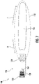
- FIG. 7 illustrates a schematic view of an embodiment of the chainsaw 100 including a clutch 164 configured to slip at a condition indicative of a specified tension in the cutting implement 112.
- the clutch 164 can be integrated within the powered element 150.
- the clutch 164 can be integrated with the carriage 128, hinged tensioner post 160, or the like.
- the clutch 164 can generally be configured to slip upon reaching a specified tension in the cutting implement 112.
- the specified tension can correspond with the desired tension of the cutting implement 112, i.e., the operational ready tension.
- the specified tension can correspond with threshold tension of the cutting implement 112, i.e., greater tension than the desired tension, whereafter the tension can be backed off to the desired tension.
- conditions indicative of desired tension in the cutting implement 112 can include threshold current draw by the powered element 150 or motor 110, acceleration of the carriage 128, determined load using one or more sensors, and the like. For instance, when the processor detects current draw by the powered element 150 exceeding a prescribed value, the processor can determine that tension has reached the specified tension.
- the cutting implement 112 may move in a reverse direction, e.g., as shown by arrow R, when the tensioning system 126 is actively adjustive tension of the cutting implement 112. In normal operation, the cutting implement 112 may move in the forward direction, e.g., as shown by arrow F.
- FIG. 8 illustrates a method 800 of adjusting tension in a cutting implement of a chainsaw.
- the method 800 includes a step 802 of adjusting a relative position of a drive sprocket with respect to a bar of the chainsaw.
- the bar can be static with respect to a housing of the chainsaw.
- the drive sprocket can be configured to drive the cutting implement.
- the method 800 can further include a step 804 of terminating further adjustment of the position of the drive sprocket after reaching a desired tension in the cutting implement.
- adjusting the relative position of the drive sprocket is performed by displacing a carriage coupled to the drive sprocket through at least one of linear translation, pivotal rotation, or a combination thereof. Displacement of the carriage can be performed manually or using one or more tension adjusting elements. Exemplary tension adjusting elements include motors or springs.
- the step 802 of adjusting the relative position of the drive sprocket can be performed until a clutch integrated into the tension adjusting system slips. Slippage of the clutch can occur when the clutch experiences a condition indicative of a specified tension in the cutting implement, such as a threshold tension in the cutting implement. After the threshold tension is reached, the step of adjusting the relative position of the drive sprocket can include backing off the adjustment from the threshold tension prior to terminating further adjustment of the position of the drive sprocket. As described with respect to FIG. 5 , backing tension off from the threshold tension condition can increase operational longevity of the cutting implement and the chainsaw while increasing safety and performance.
Landscapes
- Life Sciences & Earth Sciences (AREA)
- Engineering & Computer Science (AREA)
- Mechanical Engineering (AREA)
- Wood Science & Technology (AREA)
- Forests & Forestry (AREA)
- Sawing (AREA)
- Processing Of Stones Or Stones Resemblance Materials (AREA)
- Accommodation For Nursing Or Treatment Tables (AREA)
- Devices For Conveying Motion By Means Of Endless Flexible Members (AREA)
Abstract
Description
- The present disclosure relates generally to chainsaws, and more particularly to chainsaw tensioners.
- Chainsaws typically utilize cutting chains which include a string of links each having one or more sharpened edges. The string of links is connected to form a continuous blade which, when introduced against a surface and driven by a driving motor, can cut into the surface so as to cut through the surface.
- Over prolonged usage, the continuous blade can stretch. That is, the length of the string of links can become greater. As a result, the continuous blade may sag. Sagging in the continuous blade can result in performance reduction, the continuous blade jumping from the underlying bar, and decreased operational safety. To prevent sagging, operators typically must adjust the position of the underlying bar relative to the driving motor. This operation can be difficult due to worn components. Moreover, this manual operation is time intensive and requires that the operator carry special tools such as wrenches. Also, the interface formed between the bar and driving motor typically is in the form of a slotted engagement between the bar and housing. This slotted engagement style may reduce the strength of the connection between the bar and housing.
- Accordingly, improved chainsaws are desired in the art. In particular, chainsaws which provide improved tensioning systems would be advantageous.
- Aspects and advantages of the invention in accordance with the present disclosure will be set forth in part in the following description, or may be obvious from the description, or may be learned through practice of the technology.
- In accordance with one embodiment, a chainsaw is provided. The chainsaw includes a housing; a motor; a bar fixedly coupled to the housing and configured to form a cutting track; a cutting implement configured to move along the cutting track and drivable by the motor; and a tensioning system configured to adjust tension in the cutting implement.
- In accordance with another embodiment, a chainsaw is provided. The chainsaw includes a housing; a motor; a cutting track; a cutting implement configured to move along the cutting track and drivable by the motor; and a tensioning system configured to adjust tension in the cutting implement, wherein the tensioning system comprises a clutch configured to slip prior to the cutting implement exceeding a threshold tension.
- In accordance with another embodiment, a method of adjusting tension in a cutting implement of a chainsaw is provided. The method includes adjusting a relative position of a drive sprocket with respect to a bar of the chainsaw, wherein the bar is static with respect to a housing of the chainsaw, and wherein the drive sprocket is configured to drive the cutting implement; and terminating further adjustment of the position of the drive sprocket after reaching a desired tension in the cutting implement.
- These and other features, aspects and advantages of the present invention will become better understood with reference to the following description and appended claims. The accompanying drawings, which are incorporated in and constitute a part of this specification, illustrate embodiments of the technology and, together with the description, serve to explain the principles of the technology.
- A full and enabling disclosure of the present invention, including the best mode of making and using the present systems and methods, directed to one of ordinary skill in the art, is set forth in the specification, which makes reference to the appended figures, in which:
-
FIG. 1 is perspective view of a chainsaw in accordance with embodiments of the present disclosure; -
FIG. 2 is a perspective view of a chainsaw bar in accordance with embodiments of the present disclosure; -
FIG. 3 is a partially exploded perspective view of a chainsaw tensioning system in accordance with embodiments of the present disclosure; -
FIG. 4 is a partially exploded perspective view of a chainsaw tensioning system in accordance with embodiments of the present disclosure; -
FIG. 5 is a tensioning chart depicting tension of a cutting implement during a tensioning operation performed by a tensioning system in accordance with embodiments of the present disclosure; -
FIG. 6 is a partially exploded perspective view of a chainsaw tensioning system in accordance with embodiments of the present disclosure; and -
FIG. 7 is a schematic view of a chainsaw tensioning system including a clutch in accordance with embodiments of the present disclosure. - Reference now will be made in detail to embodiments of the present invention, one or more examples of which are illustrated in the drawings. The word "exemplary" is used herein to mean "serving as an example, instance, or illustration." Any implementation described herein as "exemplary" is not necessarily to be construed as preferred or advantageous over other implementations. Moreover, each example is provided by way of explanation, rather than limitation of, the technology. In fact, it will be apparent to those skilled in the art that modifications and variations can be made in the present technology without departing from the scope or spirit of the claimed technology. For instance, features illustrated or described as part of one embodiment can be used with another embodiment to yield a still further embodiment. Thus, it is intended that the present disclosure covers such modifications and variations as come within the scope of the appended claims and their equivalents. The detailed description uses numerical and letter designations to refer to features in the drawings. Like or similar designations in the drawings and description have been used to refer to like or similar parts of the invention.
- As used herein, the terms "first", "second", and "third" may be used interchangeably to distinguish one component from another and are not intended to signify location or importance of the individual components. The singular forms "a," "an," and "the" include plural references unless the context clearly dictates otherwise. The terms "coupled," "fixed," "attached to," and the like refer to both direct coupling, fixing, or attaching, as well as indirect coupling, fixing, or attaching through one or more intermediate components or features, unless otherwise specified herein. As used herein, the terms "comprises," "comprising," "includes," "including," "has," "having" or any other variation thereof, are intended to cover a non-exclusive inclusion. For example, a process, method, article, or apparatus that comprises a list of features is not necessarily limited only to those features but may include other features not expressly listed or inherent to such process, method, article, or apparatus. Further, unless expressly stated to the contrary, "or" refers to an inclusive- or and not to an exclusive- or. For example, a condition A or B is satisfied by any one of the following: A is true (or present) and B is false (or not present), A is false (or not present) and B is true (or present), and both A and B are true (or present).
- Terms of approximation, such as "about," "generally," "approximately," or "substantially," include values within ten percent greater or less than the stated value. When used in the context of an angle or direction, such terms include within ten degrees greater or less than the stated angle or direction. For example, "generally vertical" includes directions within ten degrees of vertical in any direction, e.g., clockwise or counter-clockwise.
- Benefits, other advantages, and solutions to problems are described below with regard to specific embodiments. However, the benefits, advantages, solutions to problems, and any feature(s) that may cause any benefit, advantage, or solution to occur or become more pronounced are not to be construed as a critical, required, or essential feature of any or all the claims.
- In general, chainsaws in accordance with one or more embodiments described herein can include a cutting implement, such as a chainsaw chain, configured to move along a cutting track defined by a chainsaw bar. The chainsaw can be configured to adjust tension in the cutting implement without moving the chainsaw bar. Instead, the chainsaw bar can be statically coupled to a housing of the chainsaw. To adjust tension in the cutting implement, a tensioning system can move a drive sprocket interfaced between the motor and the cutting implement. To increase tension, the drive sprocket can be moved in a direction generally away from the cutting implement. Conversely, to decrease tension the drive sprocket can be moved in a direction generally towards the cutting implement. Adjustment of tension can be performed manually or through the use of one or more tension adjusting elements, such as through one or more motors or springs configured to move the drive sprocket. In certain instances, the one or more motors can be controlled by a processor so as to control tension in the cutting implement. Use of proper tension in the cutting implement can prolong effective operational lifetime of the cutting implement, increase safety and even performance of the chainsaw.
- In certain instances, adjusting tension in the chainsaw cutting implement can be performed by adjusting the tension past a desired tension to a threshold tension. The tension can then be backed off from the threshold tension to the desired tension. Backing off tension can further prolong effective operational lifetime of the cutting implement, increase safety and even performance of the chainsaw.
- In certain instances, adjustment of the tension of the cutting implement can occur while the cutting implement is moving in a reverse direction as compared to an operational direction of the chainsaw. Use of a reverse direction while adjusting tension may prevent the operator from accidently adjusting tension of the cutting implement while actively using the chainsaw in a cutting operation. In certain embodiments, the absolute velocity of the cutting implement may be less during tension adjusting operations as compared to instances when the chainsaw is in use for cutting operations. That is, the continuous blade formed by the cutting implement may move at a slower speed when tensioning is being performed as compared to when the chainsaw is being used in a cutting capacity. These and other advantages and features of the chainsaw will now be described in greater detail below.
- Referring now to the drawings,
FIG. 1 illustrates a perspective view of anexemplary chainsaw 100 in accordance with an embodiment described herein. Thechainsaw 100 can include ahousing 102 defining ahandle 104. One or more power features 106 can be used to control thechainsaw 100. For instance, the one or more power features 106 can define an ON/OFF button for thechainsaw 100. Acontrol feature 108 can control the relative speed of a motor 110 (FIG. 3 ). As the operator increases speed of themotor 110 using thecontrol feature 108, a cutting implement 112 can move at increased speeds in acutting track 114 formed in abar 116 of thechainsaw 100. In the illustrated embodiment, thebar 116 is coupled to thehousing 102 through fasteners, such asbolts 118. As described in greater detail hereinafter, the coupling point between thebar 116 andhousing 102 may be fixed. That is, the coupling point can be static such that thebar 116 andhousing 102 do not move relative to one another. In such a manner, adjusting tension of the cutting implement 112 can be performed by a tensioning system described below. - The
chainsaw 100 may additionally include one or moresecondary handles 120 and one ormore guards 122 configured to protect the operator from flying debris, wood chips, and the like which may be scattered, for example, by the cutting implement 112 during operation of the chainsaw. -
FIG. 2 illustrates an exemplary view of thebar 116 for use with thechainsaw 100. Thebar 116 defines the cuttingtrack 114 along at least a portion of a perimeter thereof. The cutting implement 112 can move relative to thecutting track 114 in an operational direction when used to perform cutting operations. Thebar 116 can include one or more fixation points, such as a plurality ofholes 124 which allow thebar 116 to be coupled to the housing 104 (directly or through an intermediate member). As depicted inFIG. 2 , theholes 124 can be configured to statically couple thebar 116 to thehousing 104. For instance, theholes 124 can be single-position holes, i.e., non-elongated holes, which prevent thebar 116 from moving relative to thehousing 104. Static coupling between thebar 116 andhousing 104 may increase structural integrity of thechainsaw 100, extend operational life of the cutting implement 112 or another component of thechainsaw 100, or otherwise increase safety or performance of thechainsaw 100. By comparison, traditional bars are mounted to the housing through elongated slots which allow for adjustment of tension by loosening the bar relative to the housing and then sliding the bar away from the housing. - To adjust tension of the cutting implement 112, a tensioning system may be utilized. Referring to
FIG. 3 , in accordance with an exemplary embodiment of the present disclosure, atensioning system 126 can generally include acarriage 128 and atension adjusting element 130 configured to displace thecarriage 128. Thecarriage 128 can support aninterface 132 formed between themotor 110 and the cutting implement 112. Theinterface 132 can include, for example, adrive sprocket 134 coupled with themotor 110. In an embodiment, thedrive sprocket 134 can be supported by thecarriage 128. Themotor 110 can be mounted to thecarriage 128 such that thedrive sprocket 134 moves with thecarriage 128. More specifically, by way of non-limiting example, ashaft 136 extending between themotor 110 and drivesprocket 134 can extend through anopening 138 of thecarriage 128. Accordingly, as thecarriage 128 is displaced by thetension adjusting element 130, thedrive sprocket 134 can be displaced with respect to thebar 116. Because the cutting implement 112 is tensioned by the combination of thebar 116 andtensioning system 126, displacing thedrive sprocket 134 relative to thebar 116 can change tension within the cutting implement 112. - The exemplary
tension adjusting element 130 depicted inFIG. 3 includessprings carriage 128 can be configured to move in either direction corresponding withline 144. In an embodiment, thebar 116 can lie along a plane that is parallel, or generally parallel, with theline 144. - The
springs carriage 128 in the direction of theline 144. In particular, thesprings carriage 128 in a direction to impart increased tension on the cutting implement 112. That is, as thecarriage 128 is moved rearward, for example, by thesprings drive sprocket 134 can move rearward (i.e., generally away from the cutting implement 112) to increase tension in the cutting implement 112. Conversely, as thecarriage 128 moves forward or the cutting implement 112 elongates because of use, tension in the cutting implement 112 can decrease. Thus, controlling tension in the cutting implement 112 can be performed by maintaining pressure along thecarriage 128 by thesprings - In an embodiment, the
springs backplate 146 of thecarriage 128. Thebackplate 146 may be coupled with aportion 148 of thecarriage 128 in which theopening 138 is disposed. In certain instances, thebackplate 146 may be disposed behind themotor 110, such that thesprings backplate 146 away from themotor 110. In other instances, thebackplate 146 may be disposed in front of themotor 110, such that thesprings backplate 146 in a direction towards themotor 110. In yet other instances, thesprings portion 148 in which theopening 138 is disposed. Other designs and concepts can be utilized without departing from the scope of the disclosure. - In one or more embodiments, the spring rate of at least one of the
springs springs springs springs carriage 128 can be biased by only one spring, such asonly spring 140 oronly spring 142. Other alternative arrangements and properties of the springs are contemplated herein without departing from the scope of the disclosure. - In certain instances, the
springs carriage 128 by thesprings carriage 128 can include a locking mechanism (not shown) configured to lock thecarriage 128 with respect to thebar 116, thehousing 102, or both. The locking mechanism may be selectively activated to selectively induce the biasing force of thesprings carriage 128. When the locking mechanism is locked, thesprings carriage 128. Conversely, when the locking mechanism is unlocked, thesprings carriage 128 to displace. Thus, the operator can control the tension by selectively moving the locking mechanism between the locked and unlocked states. -
FIG. 4 illustrates an embodiment of thechainsaw 100 where thetensioning system 126 includes apowered element 150 configured to adjust tension of the cutting implement 112. Thepowered element 150 depicted inFIG. 4 is an electric motor. Thepowered element 150 can be configured to bias thedrive sprocket 134 in directions corresponding witharrow 144. In an embodiment, thecarriage 128 can includeguides 152 which move along corresponding guides (not shown) of thehousing 102, thebar 116, or another member. Thepowered element 150 can thus move thedrive sprocket 134 by moving thecarriage 128 along guides 152. - The
powered element 150 can be controlled by a processor coupled to a memory which is configured to store executable instructions. The executable instructions can be run by the processor to control tension in the cutting implement 112. By way of a first example, the processor can receive information regarding themotor 110, thepowered element 150, thedrive sprocket 134, or another element of thechainsaw 100, and determine a current condition, such as a current tension of the cutting implement 112. The processor can further determine a corrective adjustment necessary to reach a desired tension. The processor can then cause thepowered element 150 to displace thedrive sprocket 134 accordingly to reach the desired tension. In certain embodiments, initial displacement of thedrive sprocket 134 can cause the cutting implement 112 to exceed the desired tension. Instead, the cutting implement 112 can be biased to a threshold tension greater than the desired tension and then backed off to the desired tension. This can prevent preloading issues which might otherwise occur if chain tension were not backed off after tightening. In this regard, the tensioning operation can initially overtighten the cutting implement 112 and then reduce tension to reach a desired tension. - Referring to
FIG. 5 , atensioning chart 154 is depicted. Thetensioning chart 154 illustrates tension in the cutting implement 112 as a function of time T. Over a first period up until time T1, tension in the cutting implement 112 decreases as a result of use. For instance, when cutting large trees with a new blade, tension may decrease as a result of settling which may occur between adjacent links or even within each individual link. At time T1, tension in the cutting implement 112 is adjusted. In certain instances, T1 can occur as a result of operator choice. That is, for example, the operator may selectively control a user actuatable interface to engage thetensioning system 126. In other instances, T1 can occur as a result of detected tension in the cutting implement 112. For example, tensioning may automatically occur when the processor receives information indicating that the tension in the cutting implement 112 is below a prescribed level or range. That is, T1 can occur as a result of automated information. This automated information can be determined through manual input of threshold values, machine learning logic which determines ideal tension on an on-going basis, or the like. - At time T1, the
tensioning system 126 can increase tension in the cutting implement 112. In certain instances, tension can be increased linearly. In other instances, tension can be increased in a non-linear manner, such as asymptoticly. The tension can be increased until time T2. Time T2 can occur as a result of reaching the threshold tension of the cutting implement. This threshold tension can be manually input or determined through machine learning logic. Thetensioning system 126 can then back off the tension to a desired tension, indicated by dashedline 156. In other embodiments, thetensioning system 126 can immediately go to the desired tension rather than reach the threshold tension at time T2. Moreover, the chart illustrated inFIG. 5 is merely exemplary. Other tensioning profiles may be used without deviating from the scope of the disclosure. After continued use, the tension within the cutting implement may again decrease. The process from T1 to restore the tension to the desiredtension 156 can be then be repeated, optionally including increasing tension to the threshold tension at T2. -
FIG. 6 illustrates an embodiment of thechainsaw 100 where thepowered element 150 is configured to adjust tension of the cutting implement 112 through rotation of thecarriage 128. Similar to the embodiment illustrated inFIG. 4 , thepowered element 150 can include a motor. However, rather than cause thecarriage 128 to linearly translate as illustrated inFIG. 4 , thepowered element 150 illustrated inFIG. 6 rotates thecarriage 128 about apivot axis 158. Thepowered element 150 can be coupled to thecarriage 128 through a hingedtensioner post 160 or the like so as to rotate thecarriage 128 in a direction corresponding withline 162 without binding. While thepivot axis 158 illustrated inFIG. 6 is shown above themotor 110, in other embodiments, thepivot axis 158 can be below themotor 110 or along either side thereof. -
FIG. 7 illustrates a schematic view of an embodiment of thechainsaw 100 including a clutch 164 configured to slip at a condition indicative of a specified tension in the cutting implement 112. In certain instances, the clutch 164 can be integrated within thepowered element 150. In other instances, the clutch 164 can be integrated with thecarriage 128, hingedtensioner post 160, or the like. The clutch 164 can generally be configured to slip upon reaching a specified tension in the cutting implement 112. In some embodiments, the specified tension can correspond with the desired tension of the cutting implement 112, i.e., the operational ready tension. In other embodiments, the specified tension can correspond with threshold tension of the cutting implement 112, i.e., greater tension than the desired tension, whereafter the tension can be backed off to the desired tension. By way of non-limiting example, conditions indicative of desired tension in the cutting implement 112 can include threshold current draw by thepowered element 150 ormotor 110, acceleration of thecarriage 128, determined load using one or more sensors, and the like. For instance, when the processor detects current draw by thepowered element 150 exceeding a prescribed value, the processor can determine that tension has reached the specified tension. - It is noted that in certain instances, the cutting implement 112 may move in a reverse direction, e.g., as shown by arrow R, when the
tensioning system 126 is actively adjustive tension of the cutting implement 112. In normal operation, the cutting implement 112 may move in the forward direction, e.g., as shown by arrow F. - FIG. 8 illustrates a method 800 of adjusting tension in a cutting implement of a chainsaw. The method 800 includes a step 802 of adjusting a relative position of a drive sprocket with respect to a bar of the chainsaw. The bar can be static with respect to a housing of the chainsaw. The drive sprocket can be configured to drive the cutting implement. The method 800 can further include a step 804 of terminating further adjustment of the position of the drive sprocket after reaching a desired tension in the cutting implement.
- In an embodiment, adjusting the relative position of the drive sprocket is performed by displacing a carriage coupled to the drive sprocket through at least one of linear translation, pivotal rotation, or a combination thereof. Displacement of the carriage can be performed manually or using one or more tension adjusting elements. Exemplary tension adjusting elements include motors or springs.
- In certain instances, the step 802 of adjusting the relative position of the drive sprocket can be performed until a clutch integrated into the tension adjusting system slips. Slippage of the clutch can occur when the clutch experiences a condition indicative of a specified tension in the cutting implement, such as a threshold tension in the cutting implement. After the threshold tension is reached, the step of adjusting the relative position of the drive sprocket can include backing off the adjustment from the threshold tension prior to terminating further adjustment of the position of the drive sprocket. As described with respect to
FIG. 5 , backing tension off from the threshold tension condition can increase operational longevity of the cutting implement and the chainsaw while increasing safety and performance. - Further aspects of the invention are provided by one or more of the following embodiments:
- Embodiment 1. A chainsaw comprising: a housing; a motor; a bar fixedly coupled to the housing and configured to form a cutting track; a cutting implement configured to move along the cutting track and drivable by the motor; and a tensioning system configured to adjust tension in the cutting implement.
- Embodiment 2. The chainsaw of any one or more of the embodiments, wherein the tensioning system comprises a drive sprocket coupled to the motor and configured to drive the cutting implement, and wherein the drive sprocket is configured to be displaced with respect to the bar.
- Embodiment 3. The chainsaw of any one or more of the embodiments, wherein the tensioning system comprises: a carriage; a tension adjusting element configured to displace the carriage; and an interface between the motor and the cutting implement, the interface being configured to adjust a tension of the cutting implement when the carriage is displaced.
- Embodiment 4. The chainsaw of any one or more of the embodiments, wherein the tension adjusting element comprises at least one of a spring or a motor.
- Embodiment 5. The chainsaw of any one or more of the embodiments, wherein the bar lies along a plane, and wherein the carriage is configured to displace the interface in a direction generally parallel with the plane.
- Embodiment 6. The chainsaw of any one or more of the embodiments, wherein the carriage is configured to displace through linear translation, rotation, or a combination thereof.
- Embodiment 7. The chainsaw of any one or more of the embodiments, wherein the interface comprises a drive sprocket configured to drive the cutting implement, and wherein the drive sprocket is configured to move when the carriage is displaced.
- Embodiment 8. The chainsaw of any one or more of the embodiments, wherein the chainsaw further comprises a user actuatable interface configured to control operation of the tensioning system.
- Embodiment 9. A chainsaw comprising: a housing; a motor; a cutting track; a cutting implement configured to move along the cutting track and drivable by the motor; and a tensioning system configured to adjust tension in the cutting implement, wherein the tensioning system comprises a clutch configured to slip prior to the cutting implement exceeding a threshold tension.
- Embodiment 10. The chainsaw of any one or more of the embodiments, wherein the chainsaw further comprises a sensor configured to sense the occurrence of slip at the clutch.
- Embodiment 11. The chainsaw of any one or more of the embodiments, wherein the cutting implement is driven by a drive sprocket operatively coupled to the motor, wherein the drive sprocket is coupled with a carriage of the tensioning system, and wherein the carriage is displaceable relative to the cutting track and housing by a tensioning element comprising at least one of a spring or motor.
- Embodiment 12. The chainsaw of any one or more of the embodiments, wherein the cutting track is defined by a bar statically coupled to the housing.
- Embodiment 13. A method of adjusting tension in a cutting implement of a chainsaw, the method comprising: adjusting a relative position of a drive sprocket with respect to a bar of the chainsaw, wherein the bar is static with respect to a housing of the chainsaw, and wherein the drive sprocket is configured to drive the cutting implement; and terminating further adjustment of the position of the drive sprocket after reaching a desired tension in the cutting implement.
- Embodiment 14. The method of any one or more of the embodiments, wherein adjusting a relative position of the drive sprocket is performed by displacing a carriage coupled to the drive sprocket through at least one of linear translation, pivotal rotation, or a combination thereof.
- Embodiment 15. The method of any one or more of the embodiments, wherein displacement of the carriage is performed by a tension adjusting element, and wherein the tension adjusting element comprises at least one of a spring or a motor.
- Embodiment 16. The method of any one or more of the embodiments, wherein displacement of the carriage is performed by manually adjusting a location of the carriage.
- Embodiment 17. The method of any one or more of the embodiments, wherein the drive sprocket is interfaced with a clutch configured to slip prior to the cutting implement exceeding a threshold tension.
- Embodiment 18. The method of any one or more of the embodiments, wherein adjusting the relative position of the drive sprocket is performed until a threshold tension is reached, and wherein adjusting the relative position of the drive sprocket further comprises backing off the adjustment from the threshold tension prior to terminating further adjustment of the position of the drive sprocket.
- Embodiment 19. The method of any one or more of the embodiments, further comprising adjusting a speed of the cutting implement to a tension adjusting speed prior to adjusting the relative position of the drive sprocket.
- Embodiment 20. The method of any one or more of the embodiments, wherein the tension adjusting speed is in a reverse direction as compared to an operational direction of the chainsaw.
- This written description uses examples to disclose the invention, including the best mode, and also to enable any person skilled in the art to practice the invention, including making and using any devices or systems and performing any incorporated methods. The patentable scope of the invention is defined by the claims, and may include other examples that occur to those skilled in the art. Such other examples are intended to be within the scope of the claims if they include structural elements that do not differ from the literal language of the claims, or if they include equivalent structural elements with insubstantial differences from the literal language of the claims.
Claims (15)
- A chainsaw comprising:a housing;a motor;a bar fixedly coupled to the housing and configured to form a cutting track;
a cutting implement configured to move along the cutting track and drivableby the motor; anda tensioning system configured to adjust tension in the cutting implement. - The chainsaw of claim 1, wherein the tensioning system comprises a drive sprocket coupled to the motor and configured to drive the cutting implement, and wherein the drive sprocket is configured to be displaced with respect to the bar.
- The chainsaw of claim 1, wherein the tensioning system comprises:a carriage;a tension adjusting element configured to displace the carriage; and an interface between the motor and the cutting implement, the interface beingconfigured to adjust a tension of the cutting implement when the carriage is displaced.
- The chainsaw of claim 3, wherein the tension adjusting element comprises at least one of a spring or a motor.
- The chainsaw of claim 3, wherein the bar lies along a plane, and wherein the carriage is configured to displace the interface in a direction generally parallel with the plane.
- The chainsaw of claim 3, wherein the carriage is configured to displace through linear translation, rotation, or a combination thereof.
- The chainsaw of claim 3, wherein the interface comprises a drive sprocket configured to drive the cutting implement, and wherein the drive sprocket is configured to move when the carriage is displaced.
- The chainsaw of claims 1, 2, 3, 4, 5, 6 or 7, wherein the chainsaw further comprises a user actuatable interface configured to control operation of the tensioning system.
- A chainsaw comprising:a housing;a motor;a cutting track;a cutting implement configured to move along the cutting track and drivable by the motor; anda tensioning system configured to adjust tension in the cutting implement, wherein the tensioning system comprises a clutch configured to slip prior to the cutting implement exceeding a threshold tension.
- The chainsaw of claim 9, wherein the chainsaw further comprises a sensor configured to sense the occurrence of slip at the clutch.
- The chainsaw of claims 9 or 10, wherein the cutting implement is driven by a drive sprocket operatively coupled to the motor, wherein the drive sprocket is coupled with a carriage of the tensioning system, and wherein the carriage is displaceable relative to the cutting track and housing by a tensioning element comprising at least one of a spring or motor.
- The chainsaw of claims 9, 10 or 11, wherein the cutting track is defined by a bar statically coupled to the housing.
- A method of adjusting tension in a cutting implement of a chainsaw, the method comprising:adjusting a relative position of a drive sprocket with respect to a bar of the chainsaw, wherein the bar is static with respect to a housing of the chainsaw, and wherein the drive sprocket is configured to drive the cutting implement; andterminating further adjustment of the position of the drive sprocket after reaching a desired tension in the cutting implement.
- The method of claim 13, wherein adjusting a relative position of the drive sprocket is performed by displacing a carriage coupled to the drive sprocket through at least one of linear translation, pivotal rotation, or a combination thereof.
- The method of claim 14, wherein displacement of the carriage is performed by a tension adjusting element, and wherein the tension adjusting element comprises at least one of a spring or a motor.
Applications Claiming Priority (1)
| Application Number | Priority Date | Filing Date | Title |
|---|---|---|---|
| US202163145276P | 2021-02-03 | 2021-02-03 |
Publications (2)
| Publication Number | Publication Date |
|---|---|
| EP4039428A2 true EP4039428A2 (en) | 2022-08-10 |
| EP4039428A3 EP4039428A3 (en) | 2022-10-26 |
Family
ID=80113252
Family Applications (1)
| Application Number | Title | Priority Date | Filing Date |
|---|---|---|---|
| EP22152428.3A Withdrawn EP4039428A3 (en) | 2021-02-03 | 2022-01-20 | Chainsaws |
Country Status (5)
| Country | Link |
|---|---|
| US (1) | US12053832B2 (en) |
| EP (1) | EP4039428A3 (en) |
| CN (1) | CN114851302A (en) |
| AU (1) | AU2022200435A1 (en) |
| CA (1) | CA3147552A1 (en) |
Cited By (1)
| Publication number | Priority date | Publication date | Assignee | Title |
|---|---|---|---|---|
| EP4400281A1 (en) * | 2023-01-11 | 2024-07-17 | Prinz Gmbh | Sawing device |
Families Citing this family (3)
| Publication number | Priority date | Publication date | Assignee | Title |
|---|---|---|---|---|
| USD1118291S1 (en) * | 2021-09-08 | 2026-03-17 | Husqvarna Ab | Chainsaw |
| SE2151238A1 (en) * | 2021-10-08 | 2023-04-09 | Husqvarna Ab | Chainsaws, methods of controlling chainsaws, and computer programs implementing such methods |
| USD1078426S1 (en) * | 2023-09-01 | 2025-06-10 | Husqvarna Ab | Chainsaw |
Family Cites Families (74)
| Publication number | Priority date | Publication date | Assignee | Title |
|---|---|---|---|---|
| US2109702A (en) | 1935-03-29 | 1938-03-01 | Lange Alfonso | Chain-saw |
| US3435859A (en) * | 1968-03-22 | 1969-04-01 | Charles M Walker | Chain saw attachment |
| US4315370A (en) | 1979-07-13 | 1982-02-16 | Black & Decker Inc. | Combined saw chain tension adjuster and saw chain guard |
| US5144751A (en) * | 1991-08-09 | 1992-09-08 | Blount, Inc. | Method and apparatus for controlling saw chain tension |
| US5528835A (en) | 1994-11-29 | 1996-06-25 | Ra; Do-Jin | Chain saw tensioning apparatus |
| US6286905B1 (en) * | 1996-08-30 | 2001-09-11 | Komatsu Ltd. | Cutting device with vertical and horizontal movement |
| US6032373A (en) * | 1996-09-05 | 2000-03-07 | Peterson; Robin A. | Methods and apparatus for adjusting chain saw tension |
| US5896670A (en) * | 1997-07-24 | 1999-04-27 | Blount, Inc. | Chain tensioner for chain saw |
| DE19931250A1 (en) | 1999-07-07 | 2001-01-11 | Bosch Gmbh Robert | chainsaw |
| US6612952B1 (en) | 1999-10-28 | 2003-09-02 | Borgwarner Inc. | Blade tensioner having spring blade cantilevered from distal end of arm |
| US6944958B1 (en) | 2000-11-06 | 2005-09-20 | King William C | Chain saw chain tensioning and braking system |
| US7185437B2 (en) | 2002-11-15 | 2007-03-06 | Carlton Company | Chainsaw bar tensioning apparatus |
| DE10302872A1 (en) | 2003-01-25 | 2004-08-05 | Narex Česká Lípa a.s. | chainsaw |
| JP4282424B2 (en) | 2003-08-29 | 2009-06-24 | Ntn株式会社 | Chain tensioner |
| US6877233B1 (en) | 2004-01-08 | 2005-04-12 | Electrolux Home Products, Inc. | Chain saw adjuster mechanism with locking teeth |
| CN2715900Y (en) | 2004-08-20 | 2005-08-10 | 铁鎯电动工具有限公司 | Saw chain tensioner for electric chain saw |
| CN2822917Y (en) | 2005-07-15 | 2006-10-04 | 钟李杏枝 | Chain tension adjustment device for chain saw |
| US7743513B1 (en) | 2006-10-31 | 2010-06-29 | Mtd Products Inc | Chainsaw tensioning device |
| GB2452768A (en) | 2007-09-14 | 2009-03-18 | Husqvarna Ab | Chainsaw with tension adjusting knob and clutch arrangement |
| DE102007000750A1 (en) | 2007-09-20 | 2009-04-09 | Hilti Aktiengesellschaft | Hand tool with belt tensioning device |
| JP5179840B2 (en) | 2007-11-09 | 2013-04-10 | Ntn株式会社 | Chain tensioner |
| US7972240B2 (en) * | 2007-12-19 | 2011-07-05 | Deere & Company | Work machine with power limit control using an infinitely variable transmission |
| CA2729341C (en) * | 2008-06-24 | 2016-06-07 | Mtd Products Inc | Torque-limited chain tensioning for power tools |
| CN101758520B (en) | 2008-12-23 | 2012-11-21 | 苏州宝时得电动工具有限公司 | Chain saw |
| AT508397B1 (en) | 2009-06-25 | 2011-04-15 | Prinz Gmbh & Co Kg | CHAINSAW |
| CN101863055A (en) | 2010-04-19 | 2010-10-20 | 常州格力博工具有限公司 | Tool-free adjusting device of chain saw |
| CN201702820U (en) | 2010-04-19 | 2011-01-12 | 常州格力博工具有限公司 | Chain saw and tool-free adjusting device thereof |
| WO2011155880A1 (en) | 2010-06-07 | 2011-12-15 | Husqvarna Ab | Automatic chain tensioner |
| US8763260B2 (en) | 2010-07-13 | 2014-07-01 | Stanley Black & Decker, Inc. | Modular saw |
| CN102430810B (en) | 2010-09-29 | 2013-12-25 | 苏州宝时得电动工具有限公司 | Chain saw with saw chain tension device |
| CN201941047U (en) | 2010-12-14 | 2011-08-24 | 浙江派尼尔机电有限公司 | Chain saw |
| WO2012126501A1 (en) | 2011-03-18 | 2012-09-27 | Husqvarna Ab | Chainsaw with guide bar clamping and chain tensioning assembly |
| WO2012169943A1 (en) | 2011-06-07 | 2012-12-13 | Gardena Manufacturing Gmbh | A quick-action chain tensioning device for a chainsaw, and such mechanism and method |
| CN202326950U (en) | 2011-11-11 | 2012-07-11 | 辽宁大族冠华印刷科技股份有限公司 | Chain tensioning device |
| CN102562976A (en) | 2012-01-06 | 2012-07-11 | 浙江亚特电器有限公司 | Chain tensioning mechanism of lopper saw |
| CN202431861U (en) | 2012-01-06 | 2012-09-12 | 浙江亚特电器有限公司 | A chain tensioning mechanism for high-branch saws |
| US20150135542A1 (en) | 2012-06-06 | 2015-05-21 | Husqvarna Ab | Feedback system for bar clamping |
| CN202746523U (en) | 2012-09-20 | 2013-02-20 | 浙江格林雅动力科技有限公司 | Tool-free regulating structure for chain tension rate of electric chain saw |
| US9381666B1 (en) * | 2013-04-23 | 2016-07-05 | Andrew M. Moody | Automatic chainsaw tensioning device |
| CN103386508A (en) | 2013-08-01 | 2013-11-13 | 苏州赛特尔集团机械有限公司 | Saw blade tensioning device for band sawing machine |
| JP6307319B2 (en) | 2014-03-24 | 2018-04-04 | 株式会社椿本チエイン | Chain tensioner |
| FI125487B (en) | 2014-04-14 | 2015-10-30 | Maaselän Kone Oy | Firewood with tensioning chain |
| CN204075378U (en) | 2014-04-24 | 2015-01-07 | 常州格力博有限公司 | The saw blade tension knob of reciprocating saw |
| JP6335702B2 (en) | 2014-07-24 | 2018-05-30 | Ntn株式会社 | Chain tensioner |
| EP3135447B1 (en) * | 2015-08-31 | 2021-08-18 | Robert Bosch GmbH | Chainsaw and method for tensioning a chain thereof |
| CN107756539A (en) | 2016-07-06 | 2018-03-06 | 丁永新 | A kind of electronic felling saw with control board |
| CN106238820B (en) | 2016-08-10 | 2018-07-31 | 上海电动工具研究所(集团)有限公司 | A kind of Electric chain saw chain tensioner and guide plate clamp device |
| CN106171827B (en) | 2016-08-26 | 2022-12-09 | 苏州金莱克精密机械有限公司 | Chainsaw tool-free tensioner |
| CN206061714U (en) | 2016-08-26 | 2017-04-05 | 苏州金莱克精密机械有限公司 | The tool-free tension mechanism of chain saw |
| US10434682B2 (en) | 2016-11-22 | 2019-10-08 | Raffaele A. Bonomi | Quick chain tensioning system |
| EP3634676B1 (en) | 2017-06-09 | 2023-11-15 | Husqvarna Ab | Chainsaw and method |
| CN207105126U (en) | 2017-06-27 | 2018-03-16 | 浙江亚特电器有限公司 | A kind of electric chain saw |
| CN107234674B (en) | 2017-06-27 | 2022-09-09 | 浙江亚特电器股份有限公司 | An electric chainsaw |
| CN109877916A (en) | 2017-12-06 | 2019-06-14 | 莱克电气股份有限公司 | An electric chainsaw |
| CN207735685U (en) | 2018-01-18 | 2018-08-17 | 杭州精锋园林工具有限公司 | A kind of chain saw chain with slack adjuster |
| WO2019222249A2 (en) | 2018-05-15 | 2019-11-21 | Blount, Inc. | Dynamic saw chain tension control |
| CN208575966U (en) | 2018-05-28 | 2019-03-05 | 徐达 | A kind of saw chain tension regulating mechanism of electric chain saw |
| CN208734822U (en) | 2018-08-01 | 2019-04-12 | 苏州劲山电动工具有限公司 | A kind of chain saw tension wheel structure |
| CN209533588U (en) | 2018-08-23 | 2019-10-25 | 黄防红 | A kind of Electric chain saw chain slack adjuster |
| DE102018121838A1 (en) | 2018-09-07 | 2020-03-12 | Schaeffler Technologies AG & Co. KG | Self-adjusting chain tensioner and process for its manufacture |
| CN208929344U (en) | 2018-09-12 | 2019-06-04 | 黄防红 | A kind of Electric chain saw chain slack adjuster |
| CN209774884U (en) | 2018-12-29 | 2019-12-13 | 宁波鑫晟工具有限公司 | Tool-free tensioning device for chain saw |
| WO2020224266A1 (en) | 2019-05-06 | 2020-11-12 | 浙江亚特电器有限公司 | Tensioning mechanism and chain saw employing same |
| CN210435477U (en) | 2019-08-28 | 2020-05-01 | 周美 | Chain saw chain tension adjustment mechanism |
| CN211662218U (en) | 2019-09-10 | 2020-10-13 | 吕红波 | Electric chain saw convenient to adjust saw chain tensioning |
| CN211362620U (en) | 2019-10-18 | 2020-08-28 | 格力博(江苏)股份有限公司 | chainsaw |
| CN110640843A (en) | 2019-10-18 | 2020-01-03 | 常州格力博有限公司 | Chain saw |
| CN211362621U (en) | 2019-10-18 | 2020-08-28 | 格力博(江苏)股份有限公司 | Chain saw |
| CN211362619U (en) | 2019-10-18 | 2020-08-28 | 格力博(江苏)股份有限公司 | a chain saw |
| CN211362622U (en) | 2019-11-29 | 2020-08-28 | 格力博(江苏)股份有限公司 | Chain saw |
| CN110788938B (en) | 2019-11-29 | 2025-12-16 | 格力博(江苏)股份有限公司 | Chain saw |
| CN211135762U (en) * | 2019-12-24 | 2020-07-31 | 长沙明普机电设备有限公司 | Electric chain saw of high security |
| CN211671721U (en) | 2020-01-21 | 2020-10-16 | 浙江三锋实业股份有限公司 | A chain saw adjustment device |
| CN111109040B (en) | 2020-01-21 | 2024-05-14 | 浙江三锋实业股份有限公司 | Chain saw adjusting device |
-
2022
- 2022-01-20 EP EP22152428.3A patent/EP4039428A3/en not_active Withdrawn
- 2022-01-24 AU AU2022200435A patent/AU2022200435A1/en not_active Abandoned
- 2022-02-01 US US17/590,395 patent/US12053832B2/en active Active
- 2022-02-02 CA CA3147552A patent/CA3147552A1/en active Pending
- 2022-02-07 CN CN202210120178.4A patent/CN114851302A/en active Pending
Cited By (1)
| Publication number | Priority date | Publication date | Assignee | Title |
|---|---|---|---|---|
| EP4400281A1 (en) * | 2023-01-11 | 2024-07-17 | Prinz Gmbh | Sawing device |
Also Published As
| Publication number | Publication date |
|---|---|
| US12053832B2 (en) | 2024-08-06 |
| CN114851302A (en) | 2022-08-05 |
| US20220241878A1 (en) | 2022-08-04 |
| CA3147552A1 (en) | 2022-08-03 |
| AU2022200435A1 (en) | 2022-08-18 |
| EP4039428A3 (en) | 2022-10-26 |
Similar Documents
| Publication | Publication Date | Title |
|---|---|---|
| US12053832B2 (en) | Chainsaws | |
| US6968767B2 (en) | Saw machine having two saw blades | |
| EP4563308A1 (en) | Chainsaws and tensioning systems for chainsaws | |
| EP3323569B1 (en) | Quick chain tensioning system | |
| US6189758B1 (en) | Driving device using a flexible element to adjust the nip gap | |
| EP0145264B1 (en) | Grinding tool | |
| CN103338907A (en) | Wall or Floor Chainsaw | |
| US6851345B1 (en) | Cutting table fence | |
| CN113021650A (en) | Rope saw mechanism and rope saw device for stone cutting | |
| US5119798A (en) | Abrasive cutting apparatus including inverted cutting chain with inward facing cutting elements | |
| US20040063529A1 (en) | Guide system for tensioning a belt and a method of regulating belt tension | |
| US20170268636A1 (en) | Safety clutch | |
| US20120291604A1 (en) | Apparatus for cutting sheet material | |
| KR20030054514A (en) | The Apparatus for Controlling Automatically Tention and Serpentine Motion of Belt Conveyor | |
| US20240066742A1 (en) | Chainsaws having chain tensioning biasing elements | |
| US5440960A (en) | Sawdust removing device in sawing machine | |
| KR102735384B1 (en) | Take-Up Unit Bearing | |
| US20230241797A1 (en) | Systems and methods of chainsaw tensioning | |
| GB2394694A (en) | Submarine saw | |
| CA2010694A1 (en) | Method and apparatus for preparing skived belting | |
| US20170050826A1 (en) | Powered hand chain drive | |
| KR20020034408A (en) | Apparatus for correcting track of grinding belt | |
| EP0767716A1 (en) | Method and arrangement for sharpening saw chains, whereby a continuously moving chain causes a transverse motion of one or more files | |
| KR200179169Y1 (en) | Automatic billy roll grinding device | |
| WO1996000627A9 (en) | Method and arrangement for sharpening saw chains, whereby a continuously moving chain causes a transverse motion of one or more files |
Legal Events
| Date | Code | Title | Description |
|---|---|---|---|
| PUAI | Public reference made under article 153(3) epc to a published international application that has entered the european phase |
Free format text: ORIGINAL CODE: 0009012 |
|
| STAA | Information on the status of an ep patent application or granted ep patent |
Free format text: STATUS: REQUEST FOR EXAMINATION WAS MADE |
|
| 17P | Request for examination filed |
Effective date: 20220120 |
|
| AK | Designated contracting states |
Kind code of ref document: A2 Designated state(s): AL AT BE BG CH CY CZ DE DK EE ES FI FR GB GR HR HU IE IS IT LI LT LU LV MC MK MT NL NO PL PT RO RS SE SI SK SM TR |
|
| PUAL | Search report despatched |
Free format text: ORIGINAL CODE: 0009013 |
|
| AK | Designated contracting states |
Kind code of ref document: A3 Designated state(s): AL AT BE BG CH CY CZ DE DK EE ES FI FR GB GR HR HU IE IS IT LI LT LU LV MC MK MT NL NO PL PT RO RS SE SI SK SM TR |
|
| RIC1 | Information provided on ipc code assigned before grant |
Ipc: B27B 17/14 20060101AFI20220919BHEP |
|
| STAA | Information on the status of an ep patent application or granted ep patent |
Free format text: STATUS: THE APPLICATION IS DEEMED TO BE WITHDRAWN |
|
| 18D | Application deemed to be withdrawn |
Effective date: 20230427 |