EP4038987B1 - Verfahren und vorrichtungen für stromsparenden betrieb - Google Patents
Verfahren und vorrichtungen für stromsparenden betrieb Download PDFInfo
- Publication number
- EP4038987B1 EP4038987B1 EP20872574.7A EP20872574A EP4038987B1 EP 4038987 B1 EP4038987 B1 EP 4038987B1 EP 20872574 A EP20872574 A EP 20872574A EP 4038987 B1 EP4038987 B1 EP 4038987B1
- Authority
- EP
- European Patent Office
- Prior art keywords
- bwp
- pss
- cell
- serving cell
- switch
- Prior art date
- Legal status (The legal status is an assumption and is not a legal conclusion. Google has not performed a legal analysis and makes no representation as to the accuracy of the status listed.)
- Active
Links
Images


Classifications
-
- H—ELECTRICITY
- H04—ELECTRIC COMMUNICATION TECHNIQUE
- H04W—WIRELESS COMMUNICATION NETWORKS
- H04W52/00—Power management, e.g. Transmission Power Control [TPC] or power classes
- H04W52/02—Power saving arrangements
- H04W52/0209—Power saving arrangements in terminal devices
- H04W52/0225—Power saving arrangements in terminal devices using monitoring of external events, e.g. the presence of a signal
- H04W52/0229—Power saving arrangements in terminal devices using monitoring of external events, e.g. the presence of a signal where the received signal is a wanted signal
- H04W52/0235—Power saving arrangements in terminal devices using monitoring of external events, e.g. the presence of a signal where the received signal is a wanted signal where the received signal is a power saving command
-
- H—ELECTRICITY
- H04—ELECTRIC COMMUNICATION TECHNIQUE
- H04W—WIRELESS COMMUNICATION NETWORKS
- H04W16/00—Network planning, e.g. coverage or traffic planning tools; Network deployment, e.g. resource partitioning or cells structures
- H04W16/24—Cell structures
- H04W16/28—Cell structures using beam steering
-
- H—ELECTRICITY
- H04—ELECTRIC COMMUNICATION TECHNIQUE
- H04W—WIRELESS COMMUNICATION NETWORKS
- H04W52/00—Power management, e.g. Transmission Power Control [TPC] or power classes
- H04W52/02—Power saving arrangements
- H04W52/0203—Power saving arrangements in the radio access network or backbone network of wireless communication networks
- H04W52/0206—Power saving arrangements in the radio access network or backbone network of wireless communication networks in access points, e.g. base stations
-
- H—ELECTRICITY
- H04—ELECTRIC COMMUNICATION TECHNIQUE
- H04W—WIRELESS COMMUNICATION NETWORKS
- H04W52/00—Power management, e.g. Transmission Power Control [TPC] or power classes
- H04W52/02—Power saving arrangements
- H04W52/0209—Power saving arrangements in terminal devices
- H04W52/0212—Power saving arrangements in terminal devices managed by the network, e.g. network or access point is leader and terminal is follower
- H04W52/0216—Power saving arrangements in terminal devices managed by the network, e.g. network or access point is leader and terminal is follower using a pre-established activity schedule, e.g. traffic indication frame
-
- H—ELECTRICITY
- H04—ELECTRIC COMMUNICATION TECHNIQUE
- H04W—WIRELESS COMMUNICATION NETWORKS
- H04W52/00—Power management, e.g. Transmission Power Control [TPC] or power classes
- H04W52/02—Power saving arrangements
- H04W52/0209—Power saving arrangements in terminal devices
- H04W52/0212—Power saving arrangements in terminal devices managed by the network, e.g. network or access point is leader and terminal is follower
- H04W52/0219—Power saving arrangements in terminal devices managed by the network, e.g. network or access point is leader and terminal is follower where the power saving management affects multiple terminals
-
- H—ELECTRICITY
- H04—ELECTRIC COMMUNICATION TECHNIQUE
- H04W—WIRELESS COMMUNICATION NETWORKS
- H04W52/00—Power management, e.g. Transmission Power Control [TPC] or power classes
- H04W52/02—Power saving arrangements
- H04W52/0209—Power saving arrangements in terminal devices
- H04W52/0225—Power saving arrangements in terminal devices using monitoring of external events, e.g. the presence of a signal
- H04W52/0229—Power saving arrangements in terminal devices using monitoring of external events, e.g. the presence of a signal where the received signal is a wanted signal
-
- H—ELECTRICITY
- H04—ELECTRIC COMMUNICATION TECHNIQUE
- H04W—WIRELESS COMMUNICATION NETWORKS
- H04W52/00—Power management, e.g. Transmission Power Control [TPC] or power classes
- H04W52/02—Power saving arrangements
- H04W52/0209—Power saving arrangements in terminal devices
- H04W52/0261—Power saving arrangements in terminal devices managing power supply demand, e.g. depending on battery level
- H04W52/0274—Power saving arrangements in terminal devices managing power supply demand, e.g. depending on battery level by switching on or off the equipment or parts thereof
- H04W52/028—Power saving arrangements in terminal devices managing power supply demand, e.g. depending on battery level by switching on or off the equipment or parts thereof switching on or off only a part of the equipment circuit blocks
-
- H—ELECTRICITY
- H04—ELECTRIC COMMUNICATION TECHNIQUE
- H04W—WIRELESS COMMUNICATION NETWORKS
- H04W72/00—Local resource management
- H04W72/04—Wireless resource allocation
- H04W72/044—Wireless resource allocation based on the type of the allocated resource
- H04W72/0457—Variable allocation of band or rate
-
- H—ELECTRICITY
- H04—ELECTRIC COMMUNICATION TECHNIQUE
- H04W—WIRELESS COMMUNICATION NETWORKS
- H04W72/00—Local resource management
- H04W72/20—Control channels or signalling for resource management
- H04W72/23—Control channels or signalling for resource management in the downlink direction of a wireless link, i.e. towards a terminal
- H04W72/231—Control channels or signalling for resource management in the downlink direction of a wireless link, i.e. towards a terminal the control data signalling from the layers above the physical layer, e.g. RRC or MAC-CE signalling
-
- H—ELECTRICITY
- H04—ELECTRIC COMMUNICATION TECHNIQUE
- H04W—WIRELESS COMMUNICATION NETWORKS
- H04W72/00—Local resource management
- H04W72/20—Control channels or signalling for resource management
- H04W72/23—Control channels or signalling for resource management in the downlink direction of a wireless link, i.e. towards a terminal
- H04W72/232—Control channels or signalling for resource management in the downlink direction of a wireless link, i.e. towards a terminal the control data signalling from the physical layer, e.g. DCI signalling
-
- H—ELECTRICITY
- H04—ELECTRIC COMMUNICATION TECHNIQUE
- H04W—WIRELESS COMMUNICATION NETWORKS
- H04W76/00—Connection management
- H04W76/20—Manipulation of established connections
- H04W76/27—Transitions between radio resource control [RRC] states
-
- H—ELECTRICITY
- H04—ELECTRIC COMMUNICATION TECHNIQUE
- H04W—WIRELESS COMMUNICATION NETWORKS
- H04W76/00—Connection management
- H04W76/20—Manipulation of established connections
- H04W76/28—Discontinuous transmission [DTX]; Discontinuous reception [DRX]
-
- Y—GENERAL TAGGING OF NEW TECHNOLOGICAL DEVELOPMENTS; GENERAL TAGGING OF CROSS-SECTIONAL TECHNOLOGIES SPANNING OVER SEVERAL SECTIONS OF THE IPC; TECHNICAL SUBJECTS COVERED BY FORMER USPC CROSS-REFERENCE ART COLLECTIONS [XRACs] AND DIGESTS
- Y02—TECHNOLOGIES OR APPLICATIONS FOR MITIGATION OR ADAPTATION AGAINST CLIMATE CHANGE
- Y02D—CLIMATE CHANGE MITIGATION TECHNOLOGIES IN INFORMATION AND COMMUNICATION TECHNOLOGIES [ICT], I.E. INFORMATION AND COMMUNICATION TECHNOLOGIES AIMING AT THE REDUCTION OF THEIR OWN ENERGY USE
- Y02D30/00—Reducing energy consumption in communication networks
- Y02D30/70—Reducing energy consumption in communication networks in wireless communication networks
Definitions
- the present disclosure generally relates to wireless communications, and specifically, to methods and apparatuses for power saving operations.
- next-generation wireless communication system such as the fifth-generation (5G) New Radio (NR)
- 5G fifth-generation
- NR New Radio
- the 5G NR system is designed to provide flexibility and configurability to optimize the network services and types, accommodating various use cases such as enhanced Mobile Broadband (eMBB), massive Machine-Type Communication (mMTC), and Ultra-Reliable and Low-Latency Communication (URLLC).
- eMBB enhanced Mobile Broadband
- mMTC massive Machine-Type Communication
- URLLC Ultra-Reliable and Low-Latency Communication
- XP051765892 relates to fast SCell Activation for NR.
- US2019297577 relates to a method and a user equipment (UE) for power saving.
- QUALCOMM INCORPORATED "Potential Techniques for UE Power Saving", 3GPP DRAFT; R1-1903016, 3RD GENERATION PARTNERSHIP PROJECT (3GPP), MOBILE COMPETENCE CENTRE; 650, ROUTE DES LUCIOLES; F-06921 SOPHIA-ANTIPOLIS CEDEX; FRANCE, vol. RAN-WG1 16 February 2019 (2019-02-16), pages 1 - 33, XP051600713 relates to a power saving signal/channel for triggering adaption to UE power consumption.
- the present disclosure is directed to methods and apparatuses for power saving operations.
- a method performed by a User Equipment (UE) for power saving operations includes the UE receiving a first Radio Resource Control (RRC) configuration indicating at least one dormancy cell group, and receiving a second RRC configuration indicating a first Bandwidth Part (BWP) (on which the UE is configured with a dormant operation), for a serving cell.
- the dormant operation includes the UE performing a Channel State Information (CSI) measurement and stopping monitoring a Physical Downlink Control Channel (PDCCH).
- CSI Channel State Information
- PDCCH Physical Downlink Control Channel
- the serving cell belongs to a dormancy cell group of the at least one dormancy cell group.
- the method further includes the UE receiving a third RRC configuration indicating a second BWP, on which the UE is not configured with the dormant operation, for the serving cell, receiving a Power Saving Signal (PSS) including a bitmap. Each bit in the bitmap is associated with one of the at least one dormancy cell group.
- the method further includes determining an active BWP of the serving cell as the first BWP after determining that a bit associated with the dormancy cell group in the bitmap is set to a first value, and determining the active BWP of the serving cell as the second BWP after determining that the bit is set to a second value.
- PSS Power Saving Signal
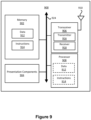
- a UE for power saving operations includes a memory and at least one processor coupled to the memory.
- the at least one processor is configured to receive a first RRC configuration indicating at least one dormancy cell group, and receive a second RRC configuration indicating a first BWP (on which the UE is configured with a dormant operation) for a serving cell.
- the dormant operation includes the UE performing a CSI measurement and stopping monitoring a PDCCH.
- the serving cell belongs to a dormancy cell group of the at least one dormancy cell group.
- the at least one processor is further configured to receive a third RRC configuration indicating a second BWP (on which the UE is not configured with the dormant operation) for the serving cell, receive a PSS including a bitmap. Each bit in the bitmap is associated with one of the at least one dormancy cell group.
- the at least one processor is further configured to determine an active BWP of the serving cell as the first BWP after determining that a bit associated with the dormancy cell group in the bitmap is set to a first value, and determine the active BWP of the serving cell as the second BWP after determining that the bit is set to a second value.
- references to "one implementation,” “an implementation,” “example implementation,” “various implementations,” “some implementations,” “implementations of the present disclosure,” etc., may indicate that the implementation(s) of the present disclosure so described may include a particular feature, structure, or characteristic, but not every possible implementation of the present disclosure necessarily includes the particular feature, structure, or characteristic. Further, repeated use of the phrase “in one implementation,” “in an example implementation,” or “an implementation,” do not necessarily refer to the same implementation, although they may.
- a and/or B may represent that: A exists alone, A and B exist at the same time, and B exists alone.
- a and/or B and/or C may represent that at least one of A, B, and C exists.
- the character "/" used herein generally represents that the former and latter associated objects are in an "or" relationship.
- any network function(s) or algorithm(s) described in the present disclosure may be implemented by hardware, software, or a combination of software and hardware. Described functions may correspond to modules that may be software, hardware, firmware, or any combination thereof.
- the software implementation may comprise computer-executable instructions stored on a computer-readable medium such as memory or other types of storage devices.
- one or more microprocessors or general-purpose computers with communication processing capability may be programmed with corresponding executable instructions and carry out the described network function(s) or algorithm(s).
- the microprocessors or general-purpose computers may be formed of Applications Specific Integrated Circuitry (ASIC), programmable logic arrays, and/or using one or more Digital Signal Processors (DSPs).
- ASIC Applications Specific Integrated Circuitry
- DSPs Digital Signal Processors
- the computer-readable medium may include, but is not limited to, Random Access Memory (RAM), Read-Only Memory (ROM), Erasable Programmable Read-Only Memory (EPROM), Electrically Erasable Programmable Read-Only Memory (EEPROM), flash memory, Compact Disc Read-Only Memory (CD-ROM), magnetic cassettes, magnetic tape, magnetic disk storage, or any other equivalent medium capable of storing computer-readable instructions.
- RAM Random Access Memory
- ROM Read-Only Memory
- EPROM Erasable Programmable Read-Only Memory
- EEPROM Electrically Erasable Programmable Read-Only Memory
- CD-ROM Compact Disc Read-Only Memory
- magnetic cassettes magnetic tape
- magnetic disk storage or any other equivalent medium capable of storing computer-readable instructions.
- a radio communication network architecture may typically include at least one Base Station (BS), at least one UE, and one or more optional network elements that provide connection towards a network.
- the UE may communicate with the network (e.g., a Core Network (CN), an Evolved Packet Core (EPC) network, an Evolved Universal Terrestrial Radio Access Network (E-UTRAN), a Next-Generation Core (NGC), or an Internet), through a Radio Access Network (RAN) established by the BS.
- CN Core Network
- EPC Evolved Packet Core
- E-UTRAN Evolved Universal Terrestrial Radio Access Network
- NGC Next-Generation Core
- Internet a Radio Access Network
- a UE may include, but is not limited to, a mobile station, a mobile terminal or device, a user communication radio terminal.
- a UE may be a portable radio equipment, which includes, but is not limited to, a mobile phone, a tablet, a wearable device, a sensor, or a Personal Digital Assistant (PDA) with wireless communication capability.
- PDA Personal Digital Assistant
- the UE may be configured to receive and transmit signals over an air interface to one or more cells in a RAN.
- a BS may include, but is not limited to, a Node B (NB) as in the Universal Mobile Telecommunication System (UMTS), an evolved Node B (eNB) as in the LTE-A, a Radio Network Controller (RNC) as in the UMTS, a Base Station Controller (BSC) as in the Global System for Mobile communications (GSM)/GSM Enhanced Data rates for GSM Evolution (EDGE) Radio Access Network (GERAN), a next-generation eNB (ng-eNB) as in an Evolved Universal Terrestrial Radio Access (E-UTRA) BS in connection with the 5GC, a next-generation Node B (gNB) as in the 5G Access Network (5G-AN), and any other apparatus capable of controlling radio communication and managing radio resources within a cell.
- the BS may connect to serve the one or more UEs through a radio interface to the network.
- a BS may be configured to provide communication services according to at least one of the following Radio Access Technologies (RATs): Worldwide Interoperability for Microwave Access (WiMAX), GSM (often referred to as 2G), GERAN, General Packet Radio Service (GPRS), UMTS (often referred to as 3G) based on basic Wideband-Code Division Multiple Access (W-CDMA), High-Speed Packet Access (HSPA), LTE, LTE-A, enhanced LTE (eLTE), NR (often referred to as 5G), and LTE-A Pro.
- RATs Radio Access Technologies
- the BS may be operable to provide radio coverage to a specific geographical area using a plurality of cells included in the RAN.
- the BS may support the operations of the cells.
- Each cell may be operable to provide services to at least one UE within its radio coverage. More specifically, each cell (often referred to as a serving cell) may provide services to serve one or more UEs within its radio coverage (e.g., each cell schedules the Downlink (DL) and optionally Uplink (UL) resources to at least one UE within its radio coverage for DL and optionally UL packet transmissions).
- the BS may communicate with one or more UEs in the radio communication system through the plurality of cells.
- a cell may allocate Sidelink (SL) resources for supporting Proximity Service (ProSe), LTE SL services, and LTE/NR Vehicle-to-Everything (V2X) services. Each cell may have overlapped coverage areas with other cells.
- MR-DC Multi-RAT Dual Connectivity
- a Primary Cell (PCell) may refer to the SpCell of an MCG.
- a Primary SCG Cell (PSCell) may refer to the SpCell of an SCG.
- MCG may refer to a group of serving cells associated with the Master Node (MN), comprising the SpCell and optionally one or more Secondary Cells (SCells).
- An SCG may refer to a group of serving cells associated with the Secondary Node (SN), comprising of the SpCell and optionally one or more SCells.
- the frame structure for NR is to support flexible configurations for accommodating various next-generation (e.g., 5G) communication requirements, such as eMBB, mMTC, and URLLC, while fulfilling high reliability, high data rate, and low latency requirements.
- the orthogonal frequency-division multiplexing (OFDM) technology may serve as a baseline for an NR waveform.
- the scalable OFDM numerology such as the adaptive sub-carrier spacing, the channel bandwidth, and the cyclic prefix (CP), may also be used.
- two coding schemes are considered for NR: (1) low-density parity-check (LDPC) code and (2) polar code.
- the coding scheme adaption may be configured based on the channel conditions and/or the service applications.
- DL transmission data in a transmission time interval of a single NR frame, at least DL transmission data, a guard period, and UL transmission data should be included, where the respective portions of the DL transmission data, the guard period, the UL transmission data should also be configurable, for example, based on the network dynamics of NR.
- an SL resource may also be provided in an NR frame to support ProSe services.
- UE battery life may strongly affect the user's experience and influence the adoption of 5G NR handsets and/or services.
- the power efficiency for 5G NR UE(s) can be better than that for LTE UE(s), and techniques and designs for improvements have been identified and adopted. For example, techniques such as UE adaptation in Frequency (e.g., BWP and/or CA/DC), UE adaptation in Time (e.g., PSS mechanism), and/or UE adaptation in traffic (e.g., dynamic maximum MIMO layer configuration) are provided to improve UE's power efficiency.
- Frequency e.g., BWP and/or CA/DC
- UE adaptation in Time e.g., PSS mechanism
- UE adaptation in traffic e.g., dynamic maximum MIMO layer configuration
- UE BWP adaptation or Bandwidth Adaptation may refer to a procedure that a BS (e.g., gNB) may dynamically switch the UE's active (DL/UL) BWP based on the traffic to support efficient operations of BWP switch, thereby reducing the UE's power consumption.
- a BS e.g., gNB
- the gNB may configure the UE with UL BWP(s) and DL BWP(s).
- the gNB may at least configure the UE with DL BWP(s) (e.g., there may be no UL BWP(s)).
- the initial BWP may be the BWP used for initial access.
- the initial BWP may be the BWP configured for the UE to first operate at SCell activation.
- the reception and transmission bandwidth of a UE does not need to be as large as the bandwidth of the cell and can be adjusted.
- the bandwidth may be ordered to change (e.g., to shrink during the period of low activity to save power), the location of the bandwidth may be adjusted in the frequency domain (e.g., to increase scheduling flexibility), and the subcarrier spacing may be ordered to change (e.g., to allow different services).
- a subset of the total cell bandwidth of a cell may refer to a BWP.
- BA may be achieved by configuring a UE with one or more BWPs and notifying the UE that which of the configured BWPs is currently active.
- a UE configured to operate in the BWPs of a serving cell may be configured with a set of BWPs for DL receptions (e.g., a DL BWP set), e.g., by a parameter BWP-Downlink (e.g., specified in the 3GPP TS 38.331 V15.5.5.0); the UE may also be configured with a set of BWPs for UL transmissions (e.g., a UL BWP set), e.g., by parameter BWP-Uplink.
- BWP switch for a serving cell may refer to a procedure used to activate an inactive BWP and deactivate an active BWP at a time.
- BWP switch may be controlled by a PDCCH (e.g., indicating a DL assignment or an UL grant), a BWP inactivity timer ( bwp-InactivityTimer ), RRC signaling, or the MAC entity (upon the initiation of an RA procedure).
- the DL BWP and UL BWP indicated by firstActiveDownlinkBWP-Id and firstActiveUplinkBWP-Id, respectively, may become active even if a PDCCH indicating a DL assignment or an UL grant is not received.
- the active BWP for a serving cell may be indicated by RRC signaling or a PDCCH.
- a DL BWP may be paired with an UL BWP.
- BWP switch may be common for both UL and DL transmissions.
- UE adaptation to CA may allow a BS (e.g., a gNB) rapidly activate/deactivate an SCell based on the traffic, in order to support efficient operations for fast SCell activation/deactivation and achieve UE power saving.
- a BS e.g., a gNB
- two or more CCs are aggregated.
- a UE may simultaneously receive or transmit on one or multiple CCs depending upon the UE's capability.
- CA may support both contiguous and non-contiguous CCs.
- frame timing and SFN may be aligned across the cells that can be aggregated. To enable reasonable UE battery consumption when CA is configured, the activation/deactivation mechanism of cells is provided.
- the UE When an SCell is deactivated, the UE does not need to monitor the PDCCH(s) or PDSCH(s) corresponding to the deactivated SCell and does not perform UL transmissions corresponding to the deactivated SCell. In addition, the UE may not need to perform CQI measurements. Conversely, when an SCell is activated, the UE may need to monitor the corresponding PDSCH(s) and PDCCH(s) (if the UE is configured to monitor PDCCH on this SCell) and is expected to be able to perform CQI measurements on the SCell.
- the UE power saving schemes with UE adaptation to the traffic may be used to reduce the maximum number of antenna/panels or MIMO layers semi-statically or dynamically indicated by the NW to achieve the purpose of UE power saving.
- the NW may indicate the maximum MIMO layer to be used for PDSCH and/or PUSCH transmissions in all BWPs of a serving cell.
- L max the maximum number of MIMO layers
- a UE can activate/deactivate its antenna-related elements to reduce the power consumption. For example, the UE may activate the smallest number of the antenna-related elements that is enough to receive the L max MIMO layers.
- the antenna-related elements may refer to a set of components including RF chain(s), RF path(s) (mixer(s), power amplifier(s), phase shifter(s), etc.), panel(s), physical antenna elements(s), etc.
- the set of components may be turned on/off based on UE implementation, and therefore, the impact from the antenna adaptation can be different for each UE.
- a UE may be configured with a DRX operation that controls the UE's PDCCH monitoring activity.
- the UE may monitor PDCCH(s) according to specific requirements (e.g., specified in the 3GPP TS 38.321 V15.5.0).
- specific requirements e.g., specified in the 3GPP TS 38.321 V15.5.0.
- the UE may monitor the PDCCH discontinuously during the DRX operation; otherwise, the UE may monitor the PDCCH in a normal way (e.g., specified in the 3GPP TS 38.213 V15.5.0).
- a PSS may include a WUS indication (e.g., a wake-up indicator).
- the PSS may trigger a UE (or the MAC entity of the UE) to "wake up" to monitor a PDCCH for the next occurrence of the DRX On-duration (e.g., to start drx-onDuration Timer ).
- the PSS may be configured jointly with DRX operation. For example, the PSS may be configured only when the DRX operation is configured.
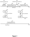
- FIG. 1 illustrates an example of a PSS scheme in accordance with an implementation of the present disclosure.
- the PSS may be monitored at the occasion(s) (e.g., the PSS monitoring occasion 102 and/or 106) located at a configured offset before the start of a timer (e.g., drx-onDurationTimer ) .
- a timer e.g., drx-onDurationTimer
- the UE may start the drx-onDurationTimer at the beginning of the DRX cycle.
- the UE may not start the drx-onDurationTimer at the beginning of the DRX cycle. For example, once the UE receives the PSS, the PHY layer 112 of the UE may provide a wake-up indicator to the MAC entity 114 of the UE. Then the UE (or MAC entity 114) may start the timer (e.g., drx-onDurationTimer ) at the beginning of an associated DRX cycle. If the PHY layer 112 does not provide a wake-up indicator to the MAC entity 114, the UE (or MAC entity 114) may not start the timer (e.g., drx-onDurationTimer ) at the beginning of the associated DRX cycle.
- the PHY layer 112 does not provide a wake-up indicator to the MAC entity 114
- the UE or MAC entity 114 may not start the timer (e.g., drx-onDurationTimer ) at the beginning of the associated DRX cycle
- the UE may start the drx-onDurationTimer at the beginning of the subsequent DRX cycle (e.g., at the beginning of the DRX On-duration 104).
- the UE may not start the timer (e.g., drx-onDurationTimer ) at the beginning of the subsequent DRX cycle.
- the PSS may (only) be configured on the PCell in case of CA and the SpCell in case of DC (e.g., the PCell in an MCG and a PSCell in an SCG).
- a new (UE-specific) RNTI (e.g., PS-RNTI) may be introduced for PSS decoding.
- a UE-specific configuration of the search space set(s) may be dedicated to the PSS for the UE to monitor.
- the CORESET for the PSS may be configured with the same or different CORESET(s) configured for other PDCCH monitoring.
- One or more than one monitoring occasions may be configured with an offset (e.g., in a slot or multiple slots) before the DRX On-duration or DRX cycle.
- UE may (only) monitor the PSS on the active (DL) BWP in an active cell.
- the maximum number of MIMO layers (which may be denoted as L max ) may be configured per a cell basis by higher layer signaling (by PDSCH-ServingCellConfig for DL and PUSCH-ServingCellConfig for UL).
- the indicated maximum number of MIMO layers may be used for PDSCH/PUSCH transmissions in all BWPs of the serving cell.
- Dynamic antenna adaptation (based on UE implementation) may still be supportable even if L max is a per-cell configuration. However, configuring L max on a cell basis may be an inefficient way when there is no or less traffic.
- the UE may switch its active BWP to a default BWP (e.g., a narrow BWP). However, the UE may still need to activate its antennas based on the per-cell configured L max , even if the UE has operated in the default BWP. In view of this, if the default BWP can be configured with different values of L max , the gNB may configure a smaller L max value for the default BWP, so that the UE can deactivate one or more antennas when the default BWP is activated, thereby reducing the UE's power consumption.
- a default BWP e.g., a narrow BWP
- L max may be configured per a BWP basis.
- the gNB may instruct a UE to switch its BWP dynamically for antenna adaptation.
- the maximum number of MIMO layers, L max may be configured per a BWP basis, and the UE may use this per-BWP configured L max value and ignore the per-cell configured L max value (e.g., provided in the PDSCH-ServingCellConfig IE and/or PUSCH-ServingCellConfig IE) when operating in the (default) BWP.
- the UE may turn to use the per-cell configured L max value when operating in the BWP.
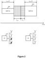
- FIG. 2 illustrates an example of the adaptation of the maximum number of antennas and/or MIMO layers, in accordance with an implementation of the present disclosure.
- the maximum number of MIMO layers, L max can be separately configured for each BWP.
- the L max is 2 for the BWP #1 202 and is 4 for the BWP #2 204.
- the UE 222 can activate fewer antennas (e.g., only two of four receive antennas are activated) when operating in the BWP #1 202. In this way, the power consumption of the UE 222 can be dynamically adjusted through a BWP switch.
- the NW may indicate the BWP switch for the UE to change the BWP and the maximum number of MIMO layers associated with the target BWP.
- scheduling DCI and/or PDCCH
- a time gap/delay e.g., T ant
- an antenna switch e.g., the activation/deactivation of one or more antennas
- the time gap/delay T ant for the antenna switch may be required in addition to the BWP switch delay (e.g., T bwp ).
- the adaptation of the maximum number of MIMO layers may lead to data interruption. Additionally, the number of affected slots may become larger as SCS is increased and may reduce the scheduling flexibility.
- a method of performing the adaptation of the maximum number of MIMO layers (and/or BWPs) before a DRX On-duration and/or DRX cycle or outside the DRX active time may be applied.
- the method can be achieved by including a BWP index in the PSS (and/or the WUS). In this way, the PSS may be used to indicate the BWP switch.
- Other implementations may be described in the following.
- a PSS may be configured only on a PCell (in case of CA) and/or an SpCell (in case of DC), where the SpCell may be a PCell in an MCG or a PSCell in an SCG.
- the PSS may not be configured on the SCell(s).
- the UE may only receive the PSS on a PCell or an SpCell from the NW, and may not receive the PSS on the SCell(s) from the NW.
- a serving cell may be configured with one or multiple BWPs, and the corresponding BWP operation (e.g., BWP switch and/or BWP-related timer operations) may be controlled per serving cell.
- BWP switch and/or BWP-related timer operations e.g., BWP switch and/or BWP-related timer operations
- the PSS may switch only the BWP of an SpCell (e.g., a PCell or a PSCell).
- the PSS may be configured only on the SpCell.
- the UE may only monitor the PSS on the SpCell and not monitor the PSS on the SCell(s). If the UE receives a PSS on the SpCell, and the PSS instructs the UE to switch the BWP, the UE may switch only the BWP of the SpCell and may not switch the BWP of the SCell(s).
- the UE may start or restart a timer (e.g., bwp-InactivityTimer ) only for the SpCell and may not start or restart the timer for the SCell(s).
- the PSS may not include the SCell-related information (e.g., SCell ID), and therefore, the PSS may not instruct the UE to perform a BWP switch for other SCell(s).
- PSS can indicate a BWP switch of a specific serving cell(s).
- the PSS may indicate a BWP switch on each serving cell (or all the serving cells).
- the PSS may be configured only on the SpCell.
- the UE may monitor the PSS only on the SpCell, and the UE may not monitor the PSS on the SCell(s). If the UE receives a PSS on the SpCell, and the PSS indicates to the UE to switch the BWP, the UE may switch the BWP of each (activated) serving cell(s).
- the UE may switch the BWP of different (activated) serving cell(s) to a specific BWP.
- the UE may switch the BWP of different (activated) serving cell(s) to different BWPs.
- the specific BWP may be determined based on the disclosed implementations.
- the UE may switch the BWP of each (activated) serving cell(s) to a specific BWP indicated by the PSS.
- the UE may switch the BWP of each (activated) serving cell(s) to a BWP, wherein the BWP may be pre-configured by RRC signaling.
- the PSS may indicate a BWP switch on a group of serving cells.
- the group(s) of the serving cell(s) may be configured by the NW (e.g., via RRC signaling, MAC CE, etc.).
- the number of cell(s) in a group may be zero, one, or more than one.
- the NW may configure a group of the serving cell(s) for a UE. If the UE receives the PSS (e.g., on the SpCell) that indicates a BWP switch of the group of the serving cell(s), the UE may switch the BWP(s) of all the (activated) serving cell(s) included in the group of the serving cell(s) to a specific BWP.
- the specific BWP may be preconfigured by the NW and/or predefined in the 3GPP specification (e.g., default/initial BWP).
- the UE may switch the BWP(s) of all the (activated) serving cell (s) included in the group of the serving cell(s) to different BWPs.
- the NW may preconfigure different BWPs for each serving cell. For example, the NW may configure a BWP #1 to a serving cell #1, and the NW may configure a BWP #2 to a serving cell #2, wherein the cell #1 and the cell #2 are configured in the same group. If the UE receives the PSS that indicates a BWP switch of the group of the serving cell(s), the UE may switch the BWP of the serving cell #1 to the BWP #1 and may switch the BWP of the serving cell #2 to the BWP #2.
- the NW may configure two groups of the serving cell(s) for a UE.
- a first group of the serving cell(s) may include an SCell #1 and an SCell #2, and a second group of the serving cell(s) may include an SCell #3 and an SCell #4.
- the UE receives the PSS (e.g., on the SpCell) that indicates a BWP switch for the first group of the serving cell(s) (e.g., via a first indicator included in the PSS)
- the UE may perform a BWP switch for the first group of the serving cell(s), e.g., the UE may perform a BWP switch for all the serving cells configured in the first group.
- the UE may perform a BWP switch for the second group, e.g., the UE may perform a BWP switch for all the serving cells configured in the second group.
- the PSS indicates a BWP switch for a group of serving cell(s) but the number of serving cells in the group is zero, the UE may perform a BWP switch of a serving cell with corresponding cell index included in the PSS.
- the UE may switch the BWP(s) of all the (activated) serving cell(s) included in the group of serving cell(s) to a specific BWP or to different BWPs for each (activated) serving cell(s).
- Each serving cell may belong to zero, one, or multiple groups.
- the PSS may implicitly indicate a BWP switch based on where (e.g., time/frequency resource occasion) the PSS is received.
- the NW may configure one or multiple PSS monitoring occasions (e.g., on different time/frequency resources or different cells) to a UE.
- the time/frequency resource(s) or different cells may be preconfigured by the gNB via DL RRC message(s).
- the UE may determine the cell(s) on which BWP switch should be performed based on the PSS monitoring occasion on which the UE receives the PSS.
- the correspondence or association between a PSS monitoring occasion and a cell(s) may be configured by the NW or predetermined according to the 3GPP specification.
- a PSS monitoring occasion may be associated with one or multiple cells.
- a PSS monitoring occasion may be associated with one or multiple groups of serving cells.
- the UE may need to perform a BWP switch for the first cell.
- the UE may need to perform a BWP switch for the second cell.
- the UE may not perform BWP switch for other cell(s) if the UE does not receive a PSS on the other cell(s).
- a UE may monitor PSS(s) in several search spaces, CORESETs, or combinations thereof.
- the UE may need to perform a BWP switch for a first cell associated with the first search space/the first CORESET.
- the UE may need to perform a BWP switch for the second cell.
- the UE may not perform BWP switch for other cell(s) where the PSS is associated with different search spaces, CORESETs, or combinations thereof.
- the gNB may preconfigure multiple searchspaceID (e.g., specified in the 3GPP TS 38.331) for a PSS associated with multiple serving cells (e.g., SpCell, SCell).
- Each of the searchspaceID may be associated with one or more serving cells.
- the UE may need to perform a BWP switch for the corresponding serving cells.
- the PSS may explicitly indicate BWP switch on a specific serving cell (e.g., via cell index).
- the PSS may include the BWP information (e.g., BWP index) and/or the Cell information (e.g., cell index).
- the PSS may indicate to the UE to switch the active BWP to a specific BWP (e.g., indicated by the BWP information) and/or indicate the UE to switch the BWP of a specific cell (e.g., indicated by the cell information).
- the PSS may include cell information of one or more than one cell.
- the information of cell(s) may be indicated/configured by another DL signaling which is not the PSS (e.g., a MAC CE or an RRC signaling).
- the PSS may be used for cross-carrier BWP switch.
- the UE may receive the PSS on a first cell (e.g., SpCell) and perform the BWP switch on a second cell (e.g., SCell) based on the PSS.
- a first cell e.g., SpCell
- SCell e.g., SCell
- a UE's current active BWP of a first cell is a first BWP
- the UE may switch the active BWP from the first BWP of the first cell to a second BWP of the first cell.
- the PSS may indicate to the UE to switch the active BWP of all the (activated) serving cells (of the UE) to an indicated BWP (if the PSS includes BWP information but without cell information) or to an indicated BWP of an indicated cell (if the PSS includes both the BWP information and cell information).
- the UE may perform a BWP switch of the SpCell or perform BWP switch of all the (activated) serving cells (of the UE).
- the UE may perform a BWP switch of the SpCell or perform BWP switch of all the (activated) serving cells (of the UE). It is noted that performing BWP switch of a serving cell (e.g., an SpCell) may refer to switching one BWP on the serving cell to another BWP on the serving cell.
- the UE may stop/abort the ongoing RA procedure and switch the BWP for the serving cell indicated by the PSS.
- the UE receives a PSS for BWP switch for a serving cell while an RA procedure associated with the serving cell is ongoing, it is up to UE implementation whether to switch the active BWP for the serving cell or ignore the PSS for BWP switch,(except that the PSS indicates to the UE to switch the active BWP for the serving cell to a specific BWP).
- a PSS may indicate BWP switch to a specific BWP for one or more or a group of cells.
- the PSS may have a field to include a BWP ID.
- the PSS may have a field with only one bit to indicate whether the UE should switch the BWP for the one or more or group of cells. If the PSS indicates to the UE to switch the BWP for the one or more or group of cells, the UE may switch the current active BWP to a specific BWP for the serving cell. If the current active BWP for the serving cell is the same as the specific BWP for the one or more or group of cells, the UE may not perform a BWP switch for the one or more or group of cells.
- the specific BWP for the one or more or group of cells may be preconfigured by NW or specified in the specification.
- the PSS may (only and/or implicitly) indicate to the UE to switch the BWP for one or more or group of cells to the initial/default BWP.
- the UE may switch the current BWP for the one or more or group of cells to the initial/default BWP.
- the UE should switch which cell's BWP may be based on the implementations disclosed previously.
- the PSS may (only and/or implicitly) indicate BWP switch for one or more or group of cells to a specific BWP.
- the UE may switch the current BWP for one or more or group of cells to the specific BWP.
- the specific BWP may be one of the BWP configured in BWP-Downlink, BWP-DownlinkCommon, firstActiveDownlinkBWP, and/or BWP-DownlinkDedicated.
- the specific BWP may be one of the UL BWP configured in BWP-Uplink, BWP-UplinkCommon, firstActiveUplinkBWP and / or BWP-UplinkDedicated.
- the specific BWP may be configured in a configuration of PSS.
- the specific BWP may be configured in a case that the PSS is configured.
- the specific BWP may be a BWP with a narrow bandwidth.
- the specific BWP may be configured for power saving (e.g., the specific BWP may be a dormant BWP).
- the UE may determine which cell's BWP should be switched based on the implementations described above.
- the PSS may indicate to a UE to switch the BWP to a specific BWP for one or more or group of cells that is explicitly indicated by the PSS.
- the PSS may indicate to the UE to switch the current active BWP to which BWP by including a BWP ID. For example, if the UE's current active BWP is BWP ID #1, then when the UE receives a PSS (e.g., on the PSS monitoring occasion of the SpCell) and the PSS includes BWP ID #2, the UE may switch the active BWP to another BWP with BWP ID #2.
- the UE may determine which cell's BWP should be switched based on the implementations described above. If the BWP ID included in the PSS is the same as the UE's active BWP, the UE may not switch the BWP. For example, the UE may ignore the PSS for the BWP switch in this case.
- the PSS may indicate to the UE to switch the BWP to a specific BWP for one or more or a group of cells in an implicit way.
- the UE may determine which BWP to switch to for the one or more or group of cells based on where the UE receives the PSS (e.g., on specific time/frequency resource(s) or different cells).
- the different CORSESETs/search spaces may be associated with different BWPs.
- the gNB may preconfigure multiple search space IDs (e.g., parameters each denoted as searchspaceID, as specified in the 3GPP TS 38.331) associated with multiple BWPs for a PSS.
- searchspaceID may be associated with a specific BWP.
- the UE may need to perform a BWP switch for one or more or group of cells to switch to the BWP corresponding to the searchspaceID.
- a PSS may not need to perform a BWP switch. If the PSS indicates a BWP ID that is the same as the active BWP ID for a cell, the UE may not perform the BWP switch on the cell.
- the UE may not switch the active BWP. If the PSS indicates to the UE not to wake up (or to go to sleep), the UE may switch the active BWP to a specific BWP.
- the specific BWP may be a default BWP, an initial BWP, a narrow BWP, and/or a specific BWP for power saving.
- the specific BWP may be indicated/preconfigured by NW or specified in the 3GPP specification.
- the UE may not switch the active BWP. If the PSS indicates to the UE not to wake up (or to go to sleep), the UE may increase a BWP switch counter by 1. Once the BWP switch counter reaches a threshold which preconfigured by the gNB, the UE may switch the active BWP to a specific BWP.
- the specific BWP may be a default BWP, an initial BWP, a narrow BWP, and/or a specific BWP for power saving.
- the specific BWP may be indicated by NW or specified in the 3GPP specification or be predefined.
- the BWP switch counter may be set to zero once the UE receives the PSS indicates to the UE to wake up.
- the BWP switch counter may be set to zero once the UE receives a PDCCH for scheduling (e.g., for DL or UL (re)transmission).
- the UE may switch the active BWP. If the PSS indicates to the UE not to wake up (or to go to sleep), the UE may not switch the active BWP to a specific BWP.
- the specific BWP may be a BWP for scheduling.
- the UE may assume it may wake up at all serving cells (e.g., including the PCell) in the upcoming DRX On-duration.
- the UE may assume it may wake up at all serving cells belonging to the PTAG in the upcoming DRX On-duration.
- a PDCCH (e.g., a DCI for scheduling) may be received at any time in the DRX active time. If the UE receives a PDCCH for BWP switch, and the UE switches the active DL BWP to a BWP that is not a default BWP and/or an initial BWP, the UE may start or restart a timer (e.g., bwp-InactivityTimer ) associated with the active DL BWP.
- a timer e.g., bwp-InactivityTimer
- the monitoring occasion of the PSS may be configured before each DRX On-duration, and therefore, there may be a time gap (or an offset) between the PSS reception and the DRX active time.
- the NW may not schedule the UE since the UE does not stay in the DRX active time for PDCCH monitoring.
- the method(s) of determining the time for the UE to start/restart the bwp-InactivityTimer are as follows.
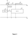
- Figure 3 illustrates the timing of starting or restarting the bwp-InactivityTimer, in accordance with an implementation of the present disclosure.
- the UE may start or restart the bwp-InactivityTimer when receiving a PSS (or PDCCH WUS).
- the UE may start or restart the bwp-InactivityTimer at time T1.
- the PSS may indicate to the UE to switch the BWP. Whether the PSS is used to indicate the UE to switch the BWP may be determined based on the implementations described above. If the PSS indicates to the UE to switch the BWP to a default/initial BWP, the UE may not start/restart the bwp-InactivityTimer, or may stop the bwp-InactivityTimer (if the bwp-InactivityTimer is running). The UE may start or restart the bwp-InactivityTimer at a symbol/slot/subframe in a PSS monitoring occasion (e.g., the PSS monitoring occasion 302) if the UE receives a PSS on the PSS monitoring occasion.
- a PSS monitoring occasion e.g., the PSS monitoring occasion 302
- the UE may start or restart the bwp-InactivityTimer associated with the corresponding serving cells (e.g., if the BWP indicated by the PSS is not a default/initial BWP).
- An example of the corresponding UE operation is in Table 1.
- the UE may start or restart the bwp-InactivityTimer when the active BWP has already been switched (e.g., switch from the BWP #1 308 to the BWP #2 310). After the UE receives the PSS for BWP switch at a DL slot on a serving cell, the UE may need some time (e.g., a time gap 312 for a BWP switch delay) to switch the BWP. In this situation, for example, the UE may start or restart the bwp-InactivityTimer at time T2.
- the UE may start performing BWP switch, and the UE may start or restart the bwp-InactivityTimer when the UE is able to receive a PDSCH (for DL active BWP switch) or transmit a PUSCH (for UL active BWP switch) on the new BWP on the serving cell.
- Whether the PSS indicates to the UE to switch the BWP may be based on the implementations described above. If the PSS indicates to the UE to switch the BWP to a default/initial BWP, the UE may not start or restart the bwp-InactivityTimer.
- the UE may stop the bwp-InactivityTimer. For example, if the PSS indicates to the UE to switch the active BWP on multiple serving cells, the UE starts or restarts the bwp-InactivityTimer associated with each corresponding serving cell based on when the active BWP of each serving cell has been switched.
- time T2 may be assigned by a gNB via a PDCCH-WUS configuration. In another example, time T2 may be a default value.
- a common T2 value may be applied for all serving cells, or a cell-specific T2 value may be configured per a serving cell basis.
- the UE may start or restart the bwp-InactivityTimer at the beginning of the DRX cycle or the DRX On-duration (e.g., the DRX On-duration 306) of the DRX cycle.
- the UE may start or restart the bwp-InactivityTimer at time T3.
- the UE may start performing the BWP switch, and the UE may start or restart the bwp-InactivityTimer at the starting symbol/slot/subframe of the first upcoming DRX cycle/On-duration.
- the PSS indicates to the UE to switch the BWP may be based on the implementations described above. If the PSS indicates to the UE to switch the BWP to a default/initial BWP, the UE may not start or restart the bwp-InactivityTimer.
- the UE may stop the bwp-InactivityTimer. For example, if the PSS indicates BWP switch on multiple serving cells, the UE may start or restart the bwp-InactivityTimer of each serving cell at the same time (e.g., if the staring symbols/slots/subframes of the DRX cycle/On-duration are the same for the serving cells).
- the UE may start or restart the bwp-InactivityTimer after "n" symbol/slot/subframe(s) when the receives the PSS, where n is a natural integer, which may be configured by the NW or specified in the 3GPP specification.
- the value of "n” may refer to an offset (e.g., the offset 304) configured for a PSS monitoring occasion (e.g., the PSS monitoring occasion 302).
- the value of "n” may be configured in a PSS configuration.
- a UE may monitor the PDCCH while the UE is in the DRX active time.
- There are several timers e.g., drx-onduration timer, drx-InactivityTimer, etc.
- events e.g., when SR is sent and is pending, etc.
- the DRX active time may cover and/or overlap with the PSS monitoring occasion(s) in the time domain. For example, UL data from the UE may arrive when the UE is not in the DRX active time.
- the UE may trigger an SR procedure to transmit an SR to request for an UL resource. Moreover, the UE may stay in the DRX active time when the SR is transmitted, and the SR procedure is pending. It is likely that the DRX active time may overlap with (e.g., partially and/or fully overlap with) the PSS monitoring occasion in the time domain.
- the drx-InactivityTimer may be started or restarted when the UE receives a PDCCH that indicates a new transmission. Consequently, it is also possible that the drx-InactivityTimer keeps running on the next PSS monitoring occasion(s).
- the UE monitors the PSS during the DRX active time because the UE has already ramped up the power to monitor the PDCCH.
- the UE-specific configuration of the search space sets(s) dedicated to the PSS monitoring may be used, which means the search space configured for the monitoring of PSS may be different from the search space configured for other DCI(s).
- monitoring the PSS in DRX active time may waste the UE's processing power due to additional blind decoding overhead, resulting in unnecessary constraints and degraded detection performance.
- Figure 4 illustrates an example of a process of a UE not monitoring a PSS in the DRX active time, in accordance with an implementation of the present disclosure.
- the UE may not monitor a PSS monitoring occasion (e.g., the PSS monitoring occasion 402) while the UE is in the DRX active time (e.g., the DRX active time 408).
- a PSS monitoring occasion e.g., the PSS monitoring occasion 402
- the DRX active time e.g., the DRX active time 408.
- the UE may start a timer (e.g., drx-onDurationTimer ) at the beginning of the subsequent DRX cycle (e.g., at the beginning of the DRX On-duration 404) if the UE does not monitor the PSS, the UE does not receive the PSS successfully, and/or the UE is in the DRX active time (e.g., the DRX active time 408) during a PSS monitoring occasion (e.g., the PSS monitoring occasion 402).
- the UE may monitor a PSS monitoring occasion (e.g., the PSS monitoring occasion 406) when the UE is not in the DRX active time.
- the PSS may be used to indicate BWP switch
- misalignments between the NW and the UE for the active BWP of the UE may occur if the UE does not monitor or detect or receive the PSS.
- the NW instructs the UE to switch from a first BWP to a second BWP via a PSS
- the UE may not switch the current active BWP and still consider the first BWP as the active BWP because the UE does not monitor or detect or receive the PSS during the PSS monitoring occasion.
- the NW may still perform scheduling on the second BWP since the NW may mistakenly consider that the active BWP of the UE has become the second BWP, causing the UE to be unable to receive scheduling information from the NW.
- the UE may mistakenly or unsuccessfully detect/receive a PSS on a PSS monitoring occasion. For example, if the NW transmits a PSS on a PSS monitoring occasion, although the UE monitors the PSS monitoring occasion, the UE may fail to receive the PSS on the PSS monitoring occasion (e.g. because the UE does not successfully decode the PSS). Furthermore, if the PSS is multipurpose (e.g., used to indicate BWP switch and wake up the UE at the same time), the failed detection/reception of the PSS may cause more issues.
- the NW instructs the UE to switch from a first BWP to a second BWP via a PSS
- the UE may not follow the PSS to switch the current active BWP due to the failed detection/reception of the PSS and may still consider the first BWP as the active BWP.
- the NW may still perform scheduling on the second BWP since the NW may mistakenly consider the active BWP of the UE has become the second BWP, causing the UE to be unable to receive scheduling information from the NW.
- the present disclosure provides one or more implementations to address these issues.
- the UE may not expect the NW to transmit a PSS during the DRX active time.
- the UE may not monitor the PSS (on the PSS monitoring occasion) during the DRX active time.
- the NW may not use the PSS to switch the UE's active BWP during the DRX active time.
- the NW may only use other scheduling DCI instead of PSS(s) to switch the UE's active BWP during the DRX active time.
- the UE may not transmit a specific message (e.g., including a confirmation message and/or feedback information) to the NW if the UE does not monitor (or does not receive) the PSS in the DRX active time.
- a confirmation message may be a MAC CE.
- the gNB may grant the UL resources on an upcoming DRX On-duration if the gNB has transmitted the PSS to instruct the UE to perform the BWP switch. Otherwise, the UE may trigger an SR procedure(s) to transmit the confirmation message.
- feedback information e.g., ACK/NACK
- the specific message (e.g., including a confirmation message and/or feedback information) may be transmitted only when the UE tries to monitor the PSS.
- the content of the specific message may vary depending upon whether the UE successfully monitors the PSS. For example, the UE may transmit an ACK to the NW if the UE successfully receives the PSS on the PSS monitoring occasion. Conversely, the UE may transmit a NACK to the NW if the UE does not (successfully) receive the PSS on the PSS monitoring occasion.
- the UE may start or restart a timer (e.g., bwp-InactivityTimer ) when the UE transmits the specific message to NW.
- a timer e.g., bwp-InactivityTimer
- the UE may perform BWP switch and transmit the specific message to the NW.
- the UE may start or restart the bwp-InactivityTimer.
- the UE may not perform the BWP switch but still transmit the specific message to NW.
- the UE may not start or restart the bwp-InactivityTimer.
- the UE may transmit signaling to the NW if the UE does not monitor (and/or does not receive) the PSS (on the PSS monitoring occasion) in the DRX active time.
- the signaling may be used to inform the NW that the UE does not monitor the PSS monitoring occasion and/or the UE unsuccessfully receives the PSS.
- the NW may transmit multiple PSSs (e.g., to perform PSS transmission repetitions) (on the PSS monitoring occasion) to a UE before a DRX On-duration (or a DRX cycle). More specifically, the PSSs may indicate the same information. For example, the NW may configure at least one of PSS monitoring occasions (on different time/frequency resources) before a DRX On-duration (or a DRX cycle). The UE may monitor at least one of the PSS monitoring occasions to decode the possible PSS.
- PSSs e.g., to perform PSS transmission repetitions
- the UE may stop monitoring the other PSS monitoring occasion before the DRX On-duration. If the UE does not receive (and/or decode successfully) a PSS on all the PSS monitoring occasion(s) before the DRX On-duration, the UE may consider the PSS is received unsuccessfully. The UE may, for example, transmit feedback to the NW to inform the NW of the unsuccessful reception of PSS.
- a PSS (e.g., which is received outside the DRX active time) may be used to activate/deactivate an SCell(s).
- the PSS may have a field to include the SCell information (e.g., SCell ID(s)).
- SCell ID(s) e.g., SCell ID(s)
- the PSS may have a field to indicate SCell activation/deactivation.
- the PSS may explicitly or implicitly indicate which SCell(s) should be activated or deactivated.
- a first SCell of a UE is activated and a second SCell of the UE is deactivated, one or more of the following implementations/examples may be applied when the UE receives a PSS.
- the PSS may not have a field to indicate SCell activation/deactivation. If the PSS includes the SCell ID of the first SCell, since the first SCell of the UE has already activated before the UE receives the PSS, the UE may deactivate the first SCell when the UE receives the PSS. If the PSS includes the SCell ID of the second SCell ID, since the second SCell of the UE has already deactivated before the UE receives the PSS, the UE may activate the second SCell when receives the PSS.
- the PSS may not have a field to indicate SCell activation/deactivation. If the PSS includes the SCell ID of the first SCell, since the first SCell of the UE has already activated before the UE receives the PSS, the UE may deactivate the first SCell when the UE receives the PSS. If the PSS includes the SCell ID of the second SCell ID, since the second SCell of the UE has already deactivated before the UE receives the PSS, the UE may activate the second SCell when receives the PSS.
- the PSS may include a field to indicate SCell activation/deactivation. If the PSS includes an SCell ID, the UE may activate or deactivate the SCell indicated by the SCell ID based on the field that indicates the SCell activation/deactivation.
- whether to activate or deactivate may be based on the PSS indicates to the UE to wake up or not wake up. If the PSS indicates to the UE to wake up and includes an SCell ID, the UE may activate the SCell indicated by the SCell ID. If the PSS indicates to the UE not to wake up and includes an SCell ID, the UE may deactivate the SCell indicated by the SCell ID.
- the UE may not perform the SCell activation/deactivation.
- which SCell(s) to be activated/deactivated by the PSS may be pre-configured. If the UE receives a PSS that includes a field to indicate SCell activation, the UE may activate (one or more or group of or all of) the SCell(s) configured by the NW. If the UE receives a PSS that includes a field to indicate SCell deactivation, the UE may deactivate (one or more or group of or all of) the SCell(s) configured by the NW.
- the MAC entity of the UE may start or restart a timer (e.g., sCellDeactivationTimer ) associated with the SCell at the time specified in the 3GPP TS 38.213.
- a timer e.g., sCellDeactivationTimer
- a PSS may be used to trigger a dormant operation of an SCell(s).
- a serving cell e.g., an SCell
- it may mean that the UE is configured with (or performs) a dormant operation on the serving cell.
- the terms “dormancy state” and “dormant operation” may be interchangeably utilized in some implementations of the present disclosure.
- the dormant operation for a serving cell may include performing CSI measurement(s) on the serving cell and stopping (or not to perform) PDCCH monitoring on the serving cell.
- the dormant operation for a serving cell may further include performing AGC for the serving cell and performing beam management for the serving cell.
- the PSS may have a field to include cell information (e.g., for one or more or group of cells).
- the PSS may have a field to indicate the dormant operation for one or more or a group of cells.
- the PSS may explicitly or implicitly indicate the cell(s) on which the UE is configured with (or performs) a dormant operation.
- the PSS may explicitly or implicitly indicate to the UE on which cell(s) the UE is configured with (or performs) the dormant operation.
- Introducing a dormancy state (or dormant operation) for a serving cell may be a solution to fast return to SCell utilization for data transfer.
- the dormant operation for a serving cell may refer to a process that the UE may stop monitoring PDCCH but continue other activities such as CSI measurements, AGC, and beam management on the serving cell.
- a first BWP of a first SCell of a UE is configured with the dormant operation and a second BWP of a second cell of the UE is not configured with the dormant operation, if the UE receives a PSS, one or more than one of the following implementations/examples may be applied.
- the PSS may have a field to indicate/activate the dormant operation for one or more or a group of SCell(s). If the PSS includes cell information for one or more or a group of SCell(s), the UE may determine whether to perform/activate the dormant operation on the BWP of the one or more or group of SCell(s) based on the field.
- whether the UE performs/activates the dormant operation on a BWP of one or more or a group of cells may be based on whether the PSS indicates to the UE to wake up. For example, if the PSS indicates to the UE to wake up and includes the SCell information of one or more or a group of SCells, the UE may not perform/activate the dormant operation on the BWP of the one or more or a group of SCells. If the PSS indicates to the UE not to wake up and includes the SCell information of one or more or a group of SCells, the UE may not perform/activate the dormant operation on the BWP of the one or more or a group of SCells.
- the UE may not change the dormant operation on the BWP of the one or more or group of SCells.
- a PSS may have a field that indicates only SCell information or SCell group information (e.g., by including an index for one or more or group of SCells) but may not have a field that indicates the dormant operation.
- the UE should perform/activate dormant operation on the BWP, of which one or more or group of SCell(s) may be pre-configured. If the UE receives a PSS that includes a field indicating the dormant operation for a group of SCells, the UE may perform/activate dormant operation on(all) the SCell(s) in the group configured by the NW.
- the UE may be configured with cross-carrier scheduling, and the PSS may be received in the scheduling cell. If the scheduling cell is instructed to activate dormant operation, all of the scheduled cells may be instructed to perform/activate dormant operation.
- the UE may be configured with cross-carrier scheduling, and the PSS may be received in the scheduling cell. If the dormant operation is configured to a specific BWP (e.g., a dormant BWP), performing BWP switch to the specific BWP for the scheduling cell may imply that all the scheduled cell(s) may have a BWP switched to the specific BWP on which the UE is configured with the dormant operation.
- a specific BWP e.g., a dormant BWP
- the PSS may include information identifying the group(s) of serving cells (e.g., among an RRC configured groups) on which the UE needs to perform/activate (or deactivate) the dormant operation.
- a bitmap may be included in the PSS. Each bit within the bitmap may indicate a group (of serving cells).
- a bit in the bitmap may be set to 1 to indicate that the UE needs to perform/activate the dormant operation on the (serving cells of the) corresponding group, which means the UE should perform the dormant operation on the active BWPs of the serving cell(s) in the group.
- the bit may be set to 0 to indicate that the UE needs to deactivate the dormant operation on the (serving cells of the) corresponding group such that the UE should not perform/activate dormant operation on the active BWPs of the serving cell(s) in the group.
- the bits in the bitmap may be associated with the groups in an ascending order. For example, the first bit in the bitmap may be associated with a group with the largest group index (or a group containing a cell having the largest cell index in the same MAC entity and the second bit in the bitmap may be associated with a group with second large group index, and so on.
- the PSS may include information identifying the group(s) of serving cells, (e.g., among an RRC configured groups) on which the UE may monitor the PDCCH on the next occurrence of the drx-onDurationTimer (of that serving cells of the group).
- the UE may determine whether to monitor a PDCCH of a serving cell (e.g., in a DRX On-duration) based on whether the UE needs to perform/activate the dormant operation on the serving cells. If the UE needs to perform/activate the dormant operation on the serving cell, the UE may not monitor a PDCCH of the serving cell (e.g., in a DRX On-duration). If the UE needs to deactivate the dormant operation on the serving cell, the UE may monitor the PDCCH of the serving cell (e.g., in a DRX On-duration).
- the UE may determine whether to start or restart the drx-onDurationTimer of a serving cell (e.g., in a DRX On-duration) based on whether the UE needs to perform/activate the dormant operation on the serving cell. If the UE needs to perform/activate the dormant operation on the serving cells, the UE may not start or restart the drx-onDurationTimer of the serving cell (e.g., in a DRX On-duration). If the UE needs to perform/activate the dormant operation on the serving cell, the UE may start or restart the drx-onDurationTimer of the serving cell (e.g., in a DRX On-duration).
- the UE may determine whether to start or restart the drx-onDurationTimer of a serving cell (e.g., on DRX On-duration) based on whether the UE receives a PSS to change the dormant operation of the serving cell. If the PSS indicates to the UE to perform/activate dormant operation on the serving cell, the UE may not start or restart the drx-onDurationTimer of the serving cell (e.g., on DRX On-duration). If the PSS indicates to the UE not to perform/activate dormant operation on the serving cell, the UE may start or restart the drx-onDurationTimer of the serving cell (e.g., on DRX On-duration).
- a UE may not monitor a PDCCH of the serving cell(s) in the group (on the next occurrence of the DRX On-duration), and the UE may monitor the PDCCH of the serving cell(s) that are not in the group (on the next occurrence of the DRX On-duration).
- a PSS e.g., on an SpCell
- the UE may not monitor a PDCCH of the serving cell(s) in the group (on the next occurrence of the DRX On-duration), and the UE may monitor the PDCCH of the serving cell(s) that are not in the group (on the next occurrence of the DRX On-duration).
- a UE may not start or restart the drx-onDurationTimer of the serving cell(s) in the group (on the next occurrence of the DRX On-duration), and the UE may start or restart the drx-onDurationTimer of the serving cell(s) which are not in the group (on the next occurrence of the DRX On-duration).
- a PSS e.g., on an SpCell
- the UE may not start or restart the drx-onDurationTimer of the serving cell(s) in the group (on the next occurrence of the DRX On-duration), and the UE may start or restart the drx-onDurationTimer of the serving cell(s) which are not in the group (on the next occurrence of the DRX On-duration).
- a UE may not monitor a PDCCH of all the serving cell(s) in the group (on the next occurrence of the DRX On-duration), and the UE may monitor a PDCCH of the serving cell(s) that are not in the group (on the next occurrence of the DRX On-duration).
- a PSS e.g., on an SpCell
- the UE may not monitor a PDCCH of all the serving cell(s) in the group (on the next occurrence of the DRX On-duration), and the UE may monitor a PDCCH of the serving cell(s) that are not in the group (on the next occurrence of the DRX On-duration).
- the dormant operation of (a BWP of) an SCell may be controlled by a timer.
- the timer may be started or restarted when the UE is instructed (e.g., via the PSS) to perform/activate the dormant operation for an SCell. While the timer is running, the UE may keep performing the dormant operation on (the BWP of) the SCell. When the timer expires, the UE may not perform/activate the dormant operation of (the BWP of) the SCell. The UE may stop the timer if the UE is instructed to not perform/activate (or to deactivate) the dormant operation of (the BWP of) the SCell.
- the NW may schedule the UE on the upcoming DRX ON duration.
- the bwp-InactivityTimer and/or the sCellDeactivationTimer may expire before the DRX ON duration.
- the UE may switch the current active BWP to the default/initial BWP and/or deactivate a SCell(s).
- the NW may not schedule the UE on the original BWP and/or the SCell. Therefore, the PSS may be used to extend the running time of the bwp-InactivityTimer and/or the sCellDeactivationTimer.
- the UE may start or restart the bwp-InactivityTimer and/or the sCellDeactivationTimer when receiving the PSS.
- the specific timing to start or restart the bwp-InactivityTimer and/or the sCellDeactivationTimer may be the same as the time for BWP switch via PSS, as described above.
- the UE may start or restart the bwp-InactivityTimer and/or the sCellDeactivationTimer when receiving the PSS, and the PSS indicates to the UE to wake up.
- the specific timing to start or restart the bwp-InactivityTimer and/or the sCellDeactivationTimer may be the same as the time for BWP switch via PSS, as described above.
- UE if the UE receives the PSS without any BWP switch command, UE will start or restart the bwp-InactivityTimer and/or the sCellDeactivationTimer at a first time; On the contrary, if the UE receiving the PSS with a BWP switch command, UE may start or restart the bwp-InactivityTimer and/or the sCellDeactivationTimer at a second time. That is, time to start the timer may depend on whether a BWP switch command is appended in the PSS.
- a BWP switch may be controlled by one or more of the following methods (a) to (e):
- the UE may not have to continuously monitor a PDCCH.
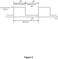
- the DRX function may be characterized by the following factors:
- each DRX cycle 502 may include a DRX On-duration 504, during which the UE may perform PDCCH monitoring.
- the rest of the time period (e.g., time interval 506) in the DRX cycle may be considered as an opportunity for DRX.
- the DRX active time may include the time during which - drx-onDurationTimer or drx-InactivityTimer or drx-RetransmissionTimerDL or drx-RetransmissionTimerUL or ra-ContentionResolutionTimer is running; or an SI is transmitted on a PUCCH, and the corresponding SI procedure is pending; or a PDCCH indicating a new transmission addressed to the C-RNTI of the MAC entity has not been received after successful reception of a RA Response for the RA Preamble not selected by the MAC entity among the contention-based RA Preamble.
- the MAC entity may not monitor the PDCCH if the PDCCH is not a complete PDCCH occasion (e.g., the DRX active time starts or ends in the middle of the PDCCH occasion).
- Active BWP switch delay applies for a UE configured with more than one BWP on PCell or any activated SCell in standalone NR or NE-DC, PCell, PSCell, or any activated SCell in MCG or SCG in NR-DC, or PSCell or any activated SCell in SCG in EN-DC.
- UE may complete the switch of active DL and/or UL BWP within the delay specified in this section.
- UE may be able to receive PDSCH (for DL active BWP switch) or transmit PUSCH (for UL active BWP switch) on the new BWP on the serving cell on which BWP switch on the first DL or UL slot occurs right after the beginning of DL slot n+ T BWPswitchDelay .
- the UE is not required to transmit UL signals or receive DL signals during time duration T BWPswitchDelay on the cell where DCI-based BWP switch occurs.
- the UE is not required to follow the requirements specified in this section when performing a DCI-based BWP switch between the BWPs in disjoint channel bandwidths or in partially overlapping channel bandwidths.
- the UE may start BWP switch at DL slot n, where n is the beginning of a DL subframe (FR1) or DL half-subframe (FR2) immediately after a BWP-inactivity timer bwp-InactivityTimer expires on a serving cell, and the UE may be able to receive PDSCH (for DL active BWP switch) or transmit PUSCH (for UL active BWP switch) on the new BWP on the serving cell on which BWP switch on the first DL or UL slot occurs right after the beginning of DL slot n+ T BWPswitchDelay .
- PDSCH for DL active BWP switch
- PUSCH for UL active BWP switch
- the UE is not required to transmit UL signals or receive DL signals after bwp-InactivityTimer expires on the cell where a timer-based BWP switch occurs.
- UE may be able to receive PDSCH/PDCCH (for DL active BWP switch) or transmit PUSCH (for UL active BWP switch) on the new BWP on the serving cell on which BWP switch occurs on the first DL or UL slot right after the beginning of DL slot n + T RRCprocessingDelay + T BWPswitchDelayRRC NR Slot length , where
- the UE is not required to transmit UL signals or receive DL signals during the time specified by T RRCprocessingDelay + T BWPswitchDelayRRC on the cell where the RRC-based BWP switch occurs.
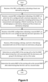
- Figure 6 illustrates a flowchart for a method performed by a UE for power saving operations, in accordance with an implementation of the present disclosure.
- actions 602, 604, 606, 608, 610, and 612 are delineated as separate actions represented as independent blocks in Figure 6 , these separately delineated actions should not be construed as necessarily order dependent.
- the order in which the actions are performed in Figure 6 is not intended to be construed as a limitation, and any number of the described blocks may be combined in any order to implement the method, or an alternate method.
- one or more of the actions 602, 604, 606, 608, 610, and 612 may be omitted in some of the present disclosure.
- the UE may receive a first RRC configuration indicating at least one dormancy cell group.
- the UE may receive a second RRC configuration indicating a first BWP, on which the UE is configured with a dormant operation, for a serving cell.
- the dormant operation may include (the UE) performing a CSI measurement and stopping a PDCCH monitoring.
- the serving cell may belong to a dormancy cell group of the at least one dormancy cell group.
- the dormant operation for the serving cell may further include at least one of (the UE) performing AGC for the serving cell, and (the UE) performing beam management for the serving cell.
- the UE may receive a third RRC configuration indicating a second BWP, on which the UE is not configured with the dormant operation, for the serving cell.
- the UE may receive a PSS including a bitmap, each bit in the bitmap associated with one of the at least one dormancy cell group.
- the PSS may be received by the UE, on a PCell or an SpCell, via DCI that is scrambled by a PS-RNTI.
- the PSS may include a wake-up indicator (e.g., WUS) for starting a DRX On-duration timer ( drx-onDurationTimer ) at a beginning of a DRX cycle.
- WUS wake-up indicator
- drx-onDurationTimer DRX On-duration timer
- the PSS may be received by the UE only on an SpCell. That is, the PSS may not be received on an SCell.
- the UE may be configured with a DRX operation.
- the UE may stop monitoring the PSS on a PDCCH monitoring occasion when the UE is in a DRX active time, where the PDCCH monitoring occasion may be configured for the PSS.
- the UE may monitor the PSS on the PDCCH monitoring occasion when the UE is not in DRX active time.
- the UE may stop monitoring the PSS on the PDCCH monitoring occasion 402 when the UE is in the DRX active time 408, and start monitoring the PSS on another PDCCH monitoring occasion 406 when the UE is not in the DRX active time 408.
- the UE may determine an active BWP of the serving cell as the first BWP after determining that a bit associated with the dormancy cell group in the bitmap is set to a first value.
- the UE may determine the active BWP of the serving cell as the second BWP after determining that the bit is set to a second value.
- the dormancy group may include more than one serving cell.
- the UE may switch the active BWPs of all of the serving cells belonging to the same dormancy cell group based on the bit.
- the active BWP may be a DL BWP.
- Figure 7 illustrates a flowchart for a method performed by a UE for power saving operations, in accordance with an implementation of the present disclosure.
- the method illustrated in Figure 7 may be performed in (or after) actions 610 and 612 illustrated in Figure 6 .
- the UE may determine whether the active BWP of the serving cell is the first BWP or the second BWP.
- the UE may perform the dormant operation on the serving cell, and/or stop PDCCH monitoring on the serving cell in a case that the active BWP of the serving cell is determined as the first BWP.
- the UE may perform the PDCCH monitoring on the serving cell.
- Figure 8 illustrates a process of controlling the dormant operation of each dormancy cell group through a PSS according to an implementation of the present disclosure.
- the serving cells of a UE may include a PCell 802, an SCell #1 804, an SCell #2 806, and an SCell #3 808.
- the UE receives a first RRC configuration indicating that SCell #1 804 and SCell #2 806 belong to the dormancy cell group #1 810, and SCell #3 808 belongs to the dormancy cell group #2 812.
- the UE also receives a second RRC configuration indicating a first BWP (which is a dormant BWP) for an SCell of the UE.
- the UE may receive a second RRC configuration indicating a first BWP#1A (which is a dormant BWP) for the SCell #1 804.
- the UE may receive a second RRC configuration indicating a first BWP#1B (which is a dormant BWP) for the SCell #2 806.
- the UE may receive a second RRC configuration indicating a first BWP#1C (which is a dormant BWP) for the SCell #3 808.
- the UE also receives a third RRC configuration indicating a second BWP (which is not a dormant BWP) for an SCell of the UE.
- the UE may receive a third RRC configuration indicating a second BWP#2A (which is not a dormant BWP) for the SCell #1 804.
- the UE may receive a third RRC configuration indicating a second BWP#2B (which is not a dormant BWP) for the SCell #2 806.
- the UE may receive a third RRC configuration indicating a second BWP#2C (which is not a dormant BWP) for the SCell #3 808.
- the first BWP configured for the SCell is activated as the active BWP, on which the dormant operation is performed.
- the SCell #1 804 is indicated as a cell on which the UE needs to perform the dormant operation
- the first BWP #1A may be activated as the active BWP of the SCell #1 804.
- the first BWP #1A may be activated as the active BWP of the SCell#1 804 and the first BWP#1B may be activated as the active BWP of the SCell#2 806.
- the UE may perform the dormant operation (e.g., performing CSI measurements but no PDCCH monitoring).
- the first BWP #1C may be activated as the active BWP of the SCell #3 808.
- the UE may perform the dormant operation on the first BWP #1C.
- the second BWP configured for the SCell is activated as the active BWP, on which the dormant operation may not be performed.
- the SCell #1 804 is indicated as a cell on which the UE does not need to perform the dormant operation
- the second BWP #2A may be activated as the active BWP of the SCell #1 804.
- the second BWP #2A may be activated as the active BWP of the SCell#1 804 and the second BWP#2B may be activated as the active BWP of the SCell#2 806.
- the UE may not perform the dormant operation. For example, the UE may perform PDCCH monitoring on the second BWP #2A.
- the second BWP #2C may be activated as the active BWP of the SCell #3 808.
- the dormant operation of a dormancy cell group is controlled by a PSS.
- the PSS 822 includes a wake-up indicator B 0 and a bitmap including several bits (e.g., a bit B 1 and a bit B 2 , etc.). Each bit in the bitmap corresponds to a dormancy cell group.
- the bit B 1 may correspond to the dormancy cell group #1 810
- the bit B 2 may correspond to the dormancy cell group #2 812.
- Each bit in the bitmap may be set to a first value (e.g., 1) to indicate that the UE needs to perform/activate the dormant operation on the serving cell(s) in the corresponding dormancy cell group (e.g., to instruct the UE activates the dormant BWP (e.g., the first BWPs #1A, 1B, and 1C in Figure 8 ) for the serving cell(s) in the corresponding dormancy cell group), or set to a second value (e.g., 0) to indicate that the UE need not perform the dormant operation (or needs to deactivate the dormant operation) on the serving cell(s) in the corresponding dormancy cell group (e.g., to instruct the UE activates the non-dormant BWP (e.g., the second BWPs #2A, 2B, and 2C in Figure 8 ) for the serving cell(s) in the corresponding dormancy cell group).
- the UE when the bit B 1 is set to the first value, the UE performs the dormant operation on all SCell(s) in the corresponding dormancy cell group #1 810. In this situation, the UE determines that the first BWP #1A, the first BWP #1B are active BWPs on the SCell #1 804 and the SCell #2 806, respectively.
- the bit B 1 when the bit B 1 is set to the second value, the UE does not perform the dormant operation on all SCell(s) in the corresponding dormancy cell group #1 810. In this situation, the UE determines that the second BWP #2A, the second BWP #2B, as active BWPs on the SCell #1 804 and the SCell #2 806, respectively.
- first BWPs e.g., the first BWP #1A, the first BWP #1B, and the first BWP #1C
- the second BWPs e.g., the second BWP #2A, the second BWP #2B, and the second BWP #2C
- the third RRC configuration may have the same BWP index or have different BWP indexes from each other.
- the serving cell(s), on which the UE may perform a BWP switch may be activated.
- the serving cell(s), on which the UE may perform a BWP switch may be an activated serving cell(s).
- the UE may only switch BWP on the activated serving cell(s).
- the UE may not switch the BWP on the deactivated serving cell(s).
- the serving cell(s) may be configured with PSS. If a serving cell(s) is not configured for PSS, the UE may not switch the BWP of that serving cell(s), e.g., even if the UE receives a PSS on another serving cell (e.g., SpCell).
- a serving cell(s) is not configured for PSS, the UE may not switch the BWP of that serving cell(s), e.g., even if the UE receives a PSS on another serving cell (e.g., SpCell).
- another serving cell e.g., SpCell
- indication for BWP switch may apply to the serving cells sharing the same search space.
- the indication(s) for the BWP switch is received through the specific search space, the targeted BWP ID may be shared as well.
- the BWP mentioned within the present disclosure may be a DL BWP or a UL BWP.
- the UE should also switch the active UL/DL BWP of the serving cell to the UL/DL BWP that has the same BWP ID as that of the DL/UL BWP indicated by the BWP switch (e.g., PSS).
- Figure 9 illustrates a block diagram of a node 900 for wireless communication, in accordance with various aspects of the present disclosure.
- the node 900 may include a transceiver 906, a processor 908, a memory 902, one or more presentation components 904, and at least one antenna 910.
- the node 900 may also include an RF spectrum band module, a BS communications module, a network communications module, and a system communications management module, Input/Output (I/O) ports, I/O components, and a power supply (not explicitly illustrated in Figure 9 ). Each of these components may be in communication with each other, directly or indirectly, over one or more buses 924.
- the node 900 may be a UE or a BS that performs various functions described herein, for example, with reference to Figures 1 through 8 .
- the transceiver 906 having a transmitter 916 (e.g., transmitting/transmission circuitry) and a receiver 918 (e.g., receiving/reception circuitry) may be configured to transmit and/or receive time and/or frequency resource partitioning information.
- the transceiver 906 may be configured to transmit in different types of subframes and slots, including, but not limited to, usable, non-usable and flexibly usable subframes and slot formats.
- the transceiver 906 may be configured to receive data and control channels.
- the node 900 may include a variety of computer-readable media.
- Computer-readable media can be any available media that can be accessed by the node 900 and include both volatile (and non-volatile) media and removable (and non-removable) media.
- Computer-readable media may include computer storage media and communication media.
- Computer storage media may include both volatile (and/or non-volatile) and removable (and/or non-removable) media implemented according to any method or technology for storage of information such as computer-readable instructions, data structures, program modules or data.
- Computer storage media may include RAM, ROM, EPROM, EEPROM, flash memory (or other memory technology), CD-ROM, Digital Versatile Disks (DVD) (or other optical disk storage), magnetic cassettes, magnetic tape, magnetic disk storage (or other magnetic storage devices), etc.
- Computer storage media do not include a propagated data signal.
- Communication media may typically embody computer-readable instructions, data structures, program modules, or other data in a modulated data signal such as a carrier wave or other transport mechanisms and include any information delivery media.
- modulated data signal may mean a signal that has one or more of its characteristics set or changed in such a manner as to encode information in the signal.
- communication media may include wired media such as a wired network or direct-wired connection, and wireless media such as acoustic, RF, infrared, and other wireless media. Combinations of any of the above should also be included within the scope of computer-readable media.
- the memory 902 may include computer storage media in the form of volatile and/or non-volatile memory.
- the memory 902 may be removable, non-removable, or a combination thereof.
- the memory 902 may include solid-state memory, hard drives, optical-disc drives, etc.
- the memory 902 may store computer-readable and/or computer-executable instructions 914 (e.g., software codes) that are configured to, when executed, cause the processor 908 to perform various functions described herein, for example, with reference to Figures 1 through 8 .
- the instructions 914 may not be directly executable by the processor 908 but may be configured to cause the node 900 (e.g., when compiled and executed) to perform various functions described herein.
- the processor 908 may include an intelligent hardware device, a Central Processing Unit (CPU), a microcontroller, an ASIC, etc.
- the processor 908 may include memory.
- the processor 908 may process the data 912 and the instructions 914 received from the memory 902, and information through the transceiver 906, the baseband communications module, and/or the network communications module.
- the processor 908 may also process information to be sent to the transceiver 906 for transmission through the antenna 910, to the network communications module for transmission to a CN.
- One or more presentation components 904 may present data indications to a person or other devices. Examples of presentation components 904 may include a display device, speaker, printing component, vibrating component, etc.
Landscapes
- Engineering & Computer Science (AREA)
- Computer Networks & Wireless Communication (AREA)
- Signal Processing (AREA)
- Mobile Radio Communication Systems (AREA)
Claims (11)
- Verfahren, das von einem Nutzerendgerät, UE (900), durchgeführt wird, für Energieeinsparungsoperationen, wobei das Verfahren aufweist:Empfangen einer ersten Funkressourcensteuerungs-, RRC-, Konfiguration, die einen Satz aus einer oder mehreren Ruhezustands-Zellengruppen (810, 812) angibt, wobei eine Gruppe von Dienstzellen (802, 804, 806, 808) zu einer spezifischen Ruhezustands-Zellengruppe (810, 812) in dem Satz aus einer oder mehreren Ruhezustands-Zellengruppen (810, 812) gehört;Empfangen einer zweiten RRC-Konfiguration, die einen ersten Bandbreitenteil, BWP, auf dem das UE (900) mit einem Ruhebetrieb konfiguriert ist, für eine Dienstzelle (802, 804, 806, 808) angibt, wobei der Ruhebetrieb das Durchführen einer Messung einer Kanalzustandsinformation, CSI, und das Stoppen einer Überwachung eines physikalischen Downlink-Steuerkanals, PDCCH, umfasst, wobei die Dienstzelle (802, 804, 806, 808) zu der Gruppe von Dienstzellen (802, 804, 806, 808) gehört;Empfangen einer dritten RRC-Konfiguration, die einen zweiten BWP, auf dem das UE (900) nicht mit dem Ruhebetrieb konfiguriert ist, für die Dienstzelle angibt;Empfangen eines Energieeinsparungssignals, PSS (822), auf einer Primärzelle, PCell, oder einer Spezialzelle, SCell, wenn sich das UE (900) nicht in einer aktiven Zeit (408) eines diskontinuierlichen Empfangs, DRX, befindet, wobei das PSS (822) eine Bitmap enthält und jedes Bit (B1, B2) in der Bitmap mit einer Ruhezustands-Zellengruppe (810, 812) in dem Satz aus einer oder mehreren Ruhezustands-Zellengruppen (810, 812) assoziiert ist;Bestimmen eines aktiven BWP der Dienstzelle (802, 804, 806, 808), die in der Gruppe von Dienstzellen (802, 804, 806, 808) enthalten ist, als den ersten BWP (1A, 1B, 1C) nach einer Bestimmung, dass ein mit der spezifischen Ruhezustands-Zellengruppe (810, 812) assoziiertes Bit (B1, B2) in der Bitmap auf einen ersten Wert gesetzt ist; undBestimmen des aktiven BWP der Dienstzelle (802, 804, 806, 808) als den zweiten BWP (2A, 2B, 2C) nach einer Bestimmung, dass das Bit (B1, B2) auf einen zweiten Wert gesetzt ist.
- Verfahren nach Anspruch 1, ferner aufweisend:
Durchführen des Ruhebetriebs in der Dienstzelle (802, 804, 806, 808), falls der aktive BWP der Dienstzelle (802, 804, 806, 808) als der erste BWP (1A, 1B, 1C) bestimmt wird. - Verfahren nach Anspruch 1, ferner aufweisend:Stoppen einer Überwachung des PDCCH in der Dienstzelle (802, 804, 806, 808), falls der aktive BWP der Dienstzelle (820, 804, 806, 808) als der erste BWP (1A, 1B, 1C) bestimmt wird; undÜberwachen des PDCCH in der Dienstzelle (802, 804, 806, 808), falls der aktive BWP der Dienstzelle als der zweite BWP (2A, 2B, 2C) bestimmt wird.
- Verfahren nach Anspruch 1, wobei der Ruhebetrieb für die Dienstzelle (802, 804, 806, 808) ferner aufweist:Durchführen einer automatischen Verstärkungssteuerung, AGC, für die Dienstzelle (802, 804, 806, 808) und/oderDurchführen eines Strahlmanagements für die Dienstzelle (802, 804, 806, 808).
- Verfahren nach Anspruch 1, wobei das PSS vom UE (900) über eine Downlink-Steuerungsinformation, DCI, empfangen wird, die mittels einer temporären Funknetz-Kennung zur Energieeinsparung, PS-RNTI, verwürfelt ist.
- Verfahren nach Anspruch 1, wobei das PSS ferner einen Weck-Indikator zum Starten eines Zeitgebers für eine DRX-Einschaltdauer, drx-onDuration Timer, am Beginn eines DRX-Zyklus enthält.
- Verfahren nach Anspruch 1, wobei das UE (900) mit einem DRX-Betrieb konfiguriert wird.
- Verfahren nach Anspruch 1, ferner aufweisend:
Umschalten aktiver BWPs aller Dienstzellen (802, 804, 806, 808), die zur Ruhezustands-Zellengruppe (810, 812) gehören, basierend auf dem Bit (B1, B2). - Verfahren nach Anspruch 1, ferner aufweisend.
Stoppen einer Überwachung des PSS bei einer PDCCH-Überwachungsgelegenheit, die für das PSS konfiguriert ist, wenn sich das UE (900) in einer aktiven Zeit eines DRX befindet. - Verfahren nach Anspruch 1, wobei es sich bei dem aktiven BWP um einen Downlink-, DL-, BWP handelt.
- Nutzerendgerät, UE (900), für Energieeinsparungsoperationen, wobei das UE (900) aufweist:einen Speicher (902); undzumindest einen Prozessor (908), der mit dem Speicher (902) gekoppelt ist, wobei der zumindest eine Prozessor (908) so konfiguriert ist, dass er das Verfahren nach einem der Ansprüche 1 bis 10 durchführt.
Applications Claiming Priority (2)
| Application Number | Priority Date | Filing Date | Title |
|---|---|---|---|
| US201962909965P | 2019-10-03 | 2019-10-03 | |
| PCT/CN2020/117635 WO2021063252A1 (en) | 2019-10-03 | 2020-09-25 | Methods and apparatuses for power saving operations |
Publications (3)
| Publication Number | Publication Date |
|---|---|
| EP4038987A1 EP4038987A1 (de) | 2022-08-10 |
| EP4038987A4 EP4038987A4 (de) | 2023-10-25 |
| EP4038987B1 true EP4038987B1 (de) | 2025-04-30 |
Family
ID=75275106
Family Applications (1)
| Application Number | Title | Priority Date | Filing Date |
|---|---|---|---|
| EP20872574.7A Active EP4038987B1 (de) | 2019-10-03 | 2020-09-25 | Verfahren und vorrichtungen für stromsparenden betrieb |
Country Status (6)
| Country | Link |
|---|---|
| US (3) | US11405868B2 (de) |
| EP (1) | EP4038987B1 (de) |
| JP (1) | JP7429286B2 (de) |
| KR (1) | KR102943254B1 (de) |
| CN (1) | CN114451019B (de) |
| WO (1) | WO2021063252A1 (de) |
Families Citing this family (28)
| Publication number | Priority date | Publication date | Assignee | Title |
|---|---|---|---|---|
| KR102891016B1 (ko) * | 2019-02-15 | 2025-11-24 | 삼성전자주식회사 | 무선 통신 시스템에서 단말의 전력 소모 감소를 위한 상향링크 제어 채널 전송 방법 및 장치 |
| CN113329449B (zh) * | 2019-05-30 | 2023-05-12 | Oppo广东移动通信有限公司 | 一种bwp的管理方法及装置、终端 |
| EP4038987B1 (de) * | 2019-10-03 | 2025-04-30 | Sharp Kabushiki Kaisha | Verfahren und vorrichtungen für stromsparenden betrieb |
| EP4709034A3 (de) * | 2019-11-07 | 2026-04-15 | Apple Inc. | Wecksignalisierung während eines diskontinuierlichen empfangszyklus |
| JP7405973B2 (ja) * | 2019-11-13 | 2023-12-26 | ノキア テクノロジーズ オサケユイチア | ランダムアクセス応答を有するウェイクアップ信号 |
| EP4057553A4 (de) * | 2019-12-09 | 2022-11-16 | Guangdong Oppo Mobile Telecommunications Corp., Ltd. | Verfahren zur steuerung eines zeitgebers für die dauer eines diskontinuierlichen empfangs, elektronische vorrichtung und speichermedium |
| CN113038635B (zh) * | 2019-12-24 | 2023-04-25 | 维沃移动通信有限公司 | Scell休眠指示处理方法、终端及网络设备 |
| CN115066940B (zh) * | 2020-02-04 | 2025-10-10 | Lg电子株式会社 | 用于无线通信系统中的休眠带宽部分的自主改变的方法和设备 |
| MX2022009675A (es) * | 2020-02-06 | 2022-09-26 | Nokia Technologies Oy | Información de enlace ascendente basada en señal de reactivación. |
| WO2021203324A1 (en) * | 2020-04-08 | 2021-10-14 | Apple Inc. | SCell Dormancy Reliability Improvement |
| WO2021243600A1 (zh) * | 2020-06-03 | 2021-12-09 | 北京小米移动软件有限公司 | 数据传输处理方法、装置、用户设备及存储介质 |
| US12047823B2 (en) * | 2020-07-14 | 2024-07-23 | Qualcomm Incorporated | Cross-carrier scheduling |
| EP4193699A1 (de) * | 2020-08-05 | 2023-06-14 | Telefonaktiebolaget LM Ericsson (publ) | Ssb-ausgerichtete übertragung von paging-bezogenen signalen |
| US20230209645A1 (en) * | 2020-09-11 | 2023-06-29 | Beijing Xiaomi Mobile Software Co., Ltd. | Drx packet wake-up method and apparatus, communication device, and storage medium |
| US11419042B2 (en) | 2021-01-13 | 2022-08-16 | PanPsy Technologies, LLC | Enhanced secondary cell activation |
| US12425990B2 (en) * | 2021-01-28 | 2025-09-23 | Qualcomm Incorporated | Time gaps in synchronization signal blocks |
| CA3209944A1 (en) * | 2021-03-10 | 2022-09-15 | Ofinno, Llc | Power saving operation for a wireless device |
| US20240163895A1 (en) * | 2021-03-11 | 2024-05-16 | Beijing Xiaomi Mobile Software Co., Ltd. | Method and apparatus for adjusting maximum number of transport layers |
| US12047311B2 (en) * | 2021-04-09 | 2024-07-23 | Qualcomm Incorporated | Techniques for switching a bandwidth part configuration |
| CN115314175B (zh) * | 2021-05-08 | 2024-08-23 | 维沃移动通信有限公司 | 带宽部分处理方法、装置及终端 |
| WO2023014207A1 (ko) * | 2021-08-06 | 2023-02-09 | 엘지전자 주식회사 | 무선 통신 시스템에서 전력 절감을 지원하기 위한 방법 및 장치 |
| US11943792B2 (en) * | 2021-08-09 | 2024-03-26 | Qualcomm Incorporated | Techniques for performing bandwidth part switching |
| CN116264736B (zh) * | 2021-12-10 | 2025-08-08 | 上海朗帛通信技术有限公司 | 一种被用于无线通信的节点中的方法和装置 |
| KR102815017B1 (ko) * | 2022-04-28 | 2025-05-30 | 엘지전자 주식회사 | 하향링크 제어 채널을 송수신하는 방법 및 이를 위한 장치 |
| US12550225B2 (en) * | 2022-11-15 | 2026-02-10 | Qualcomm Incorporated | Component carrier activation and deactivation |
| WO2024221473A1 (zh) * | 2023-04-28 | 2024-10-31 | 北京小米移动软件有限公司 | 信息传输方法及装置、通信设备及存储介质 |
| WO2025041668A1 (ja) * | 2023-08-24 | 2025-02-27 | 株式会社Nttドコモ | 端末、基地局、及び通信方法 |
| US20250261138A1 (en) * | 2024-02-13 | 2025-08-14 | Qualcomm Incorporated | Multi-mode synchronization signaling for a secondary cell |
Family Cites Families (16)
| Publication number | Priority date | Publication date | Assignee | Title |
|---|---|---|---|---|
| US11166225B2 (en) * | 2016-08-02 | 2021-11-02 | FG Innovation Company Limited | Method for signaling RAN profile index and radio communication equipment using the same |
| US10492157B2 (en) * | 2017-01-04 | 2019-11-26 | Samsung Electronics Co., Ltd. | Method and apparatus for system information delivery in advanced wireless systems |
| CN109586881B (zh) * | 2017-09-29 | 2021-11-12 | 株式会社Kt | 用于在新无线电中切换带宽部分的方法和装置 |
| US10887073B2 (en) * | 2017-10-26 | 2021-01-05 | Ofinno, Llc | Activation and deactivation of bandwidth part |
| EP3571803B1 (de) * | 2017-11-09 | 2020-04-29 | Ofinno Technologies, LLC | Verfahren und vorrichtungen zur kommunikation auf basis der fähigkeiten von drahtlosen vorrichtungen |
| CN109996338A (zh) * | 2017-12-29 | 2019-07-09 | 华为技术有限公司 | 一种确定bwp状态的方法、设备及系统 |
| CN109996333B (zh) * | 2018-01-03 | 2020-09-29 | 维沃移动通信有限公司 | 寻呼位置或驻留位置的确定方法和设备 |
| US11297674B2 (en) | 2018-02-14 | 2022-04-05 | Samsung Electronics Co., Ltd. | Method and apparatus for power savings at a user equipment |
| US10652826B2 (en) * | 2018-03-23 | 2020-05-12 | Samsung Electronics Co., Ltd. | Method and apparatus for power saving signal design in NR |
| US10856227B2 (en) * | 2018-09-28 | 2020-12-01 | Mediatek Inc. | Triggering adaptation mechanisms for UE power-saving |
| PL3866517T3 (pl) * | 2018-10-19 | 2024-04-22 | Beijing Xiaomi Mobile Software Co., Ltd. | Sposób i urządzenie do monitorowania sygnału oszczędzania energii |
| KR20210008670A (ko) * | 2019-07-15 | 2021-01-25 | 삼성전자주식회사 | 차세대 이동 통신 시스템에서 휴면 부분 대역폭을 효율적으로 운영하는 방법 및 장치 |
| US11582745B2 (en) * | 2019-08-14 | 2023-02-14 | Industrial Technology Research Institute | Method for BWP operating and user equipment using the same |
| US11463227B2 (en) * | 2019-08-16 | 2022-10-04 | Mediatek Inc. | Activated secondary cells transition between dormancy behavior and active behavior in 5G NR system |
| CN113365307B (zh) * | 2019-09-27 | 2023-03-21 | Oppo广东移动通信有限公司 | 一种测量管理方法及装置、通信设备 |
| EP4038987B1 (de) * | 2019-10-03 | 2025-04-30 | Sharp Kabushiki Kaisha | Verfahren und vorrichtungen für stromsparenden betrieb |
-
2020
- 2020-09-25 EP EP20872574.7A patent/EP4038987B1/de active Active
- 2020-09-25 JP JP2022517862A patent/JP7429286B2/ja active Active
- 2020-09-25 KR KR1020227013059A patent/KR102943254B1/ko active Active
- 2020-09-25 CN CN202080045782.4A patent/CN114451019B/zh active Active
- 2020-09-25 WO PCT/CN2020/117635 patent/WO2021063252A1/en not_active Ceased
- 2020-09-25 US US17/033,125 patent/US11405868B2/en active Active
-
2022
- 2022-06-10 US US17/837,428 patent/US11818660B2/en active Active
-
2023
- 2023-09-28 US US18/374,163 patent/US20240023023A1/en active Pending
Also Published As
| Publication number | Publication date |
|---|---|
| JP2022548745A (ja) | 2022-11-21 |
| KR20220066135A (ko) | 2022-05-23 |
| US11405868B2 (en) | 2022-08-02 |
| EP4038987A4 (de) | 2023-10-25 |
| CN114451019A (zh) | 2022-05-06 |
| EP4038987A1 (de) | 2022-08-10 |
| WO2021063252A1 (en) | 2021-04-08 |
| US20220303904A1 (en) | 2022-09-22 |
| US20210105722A1 (en) | 2021-04-08 |
| US20240023023A1 (en) | 2024-01-18 |
| US11818660B2 (en) | 2023-11-14 |
| JP7429286B2 (ja) | 2024-02-07 |
| CN114451019B (zh) | 2024-01-02 |
| KR102943254B1 (ko) | 2026-03-25 |
Similar Documents
| Publication | Publication Date | Title |
|---|---|---|
| EP4038987B1 (de) | Verfahren und vorrichtungen für stromsparenden betrieb | |
| CN114246002B (zh) | 用于pdcch监测适配的方法和设备 | |
| US11706760B2 (en) | Method and apparatus for handling repetitions of physical uplink shared channel (PUSCH) transmission in a wireless communication system | |
| WO2022083704A1 (en) | Search space group switching in next generation networks | |
| US12557116B2 (en) | User equipment and method for power saving | |
| WO2021233392A1 (en) | Method and user equipment for performing sidelink communication | |
| US12273751B2 (en) | Methods and apparatus for supporting common design of PDCCH skipping and search space set switching | |
| WO2021000707A1 (en) | Method and apparatus for performing repetition transmissions in wireless communication system | |
| WO2021110124A1 (en) | Communication method and user equipment for operations with bandwidth part switching | |
| US20240073816A1 (en) | User equipment and method for saving power | |
| US20220330215A1 (en) | Method of search space monitoring and user equipment using the same | |
| WO2025026400A1 (en) | Method and apparatus for network energy saving | |
| WO2025178034A1 (en) | Method and apparatus for network energy saving |
Legal Events
| Date | Code | Title | Description |
|---|---|---|---|
| STAA | Information on the status of an ep patent application or granted ep patent |
Free format text: STATUS: THE INTERNATIONAL PUBLICATION HAS BEEN MADE |
|
| PUAI | Public reference made under article 153(3) epc to a published international application that has entered the european phase |
Free format text: ORIGINAL CODE: 0009012 |
|
| STAA | Information on the status of an ep patent application or granted ep patent |
Free format text: STATUS: REQUEST FOR EXAMINATION WAS MADE |
|
| 17P | Request for examination filed |
Effective date: 20220222 |
|
| AK | Designated contracting states |
Kind code of ref document: A1 Designated state(s): AL AT BE BG CH CY CZ DE DK EE ES FI FR GB GR HR HU IE IS IT LI LT LU LV MC MK MT NL NO PL PT RO RS SE SI SK SM TR |
|
| DAV | Request for validation of the european patent (deleted) | ||
| DAX | Request for extension of the european patent (deleted) | ||
| A4 | Supplementary search report drawn up and despatched |
Effective date: 20230927 |
|
| RIC1 | Information provided on ipc code assigned before grant |
Ipc: H04W 52/02 20090101AFI20230921BHEP |
|
| STAA | Information on the status of an ep patent application or granted ep patent |
Free format text: STATUS: EXAMINATION IS IN PROGRESS |
|
| 17Q | First examination report despatched |
Effective date: 20240516 |
|
| GRAP | Despatch of communication of intention to grant a patent |
Free format text: ORIGINAL CODE: EPIDOSNIGR1 |
|
| STAA | Information on the status of an ep patent application or granted ep patent |
Free format text: STATUS: GRANT OF PATENT IS INTENDED |
|
| RAP1 | Party data changed (applicant data changed or rights of an application transferred) |
Owner name: SHARP KABUSHIKI KAISHA |
|
| INTG | Intention to grant announced |
Effective date: 20241128 |
|
| GRAS | Grant fee paid |
Free format text: ORIGINAL CODE: EPIDOSNIGR3 |
|
| GRAA | (expected) grant |
Free format text: ORIGINAL CODE: 0009210 |
|
| STAA | Information on the status of an ep patent application or granted ep patent |
Free format text: STATUS: THE PATENT HAS BEEN GRANTED |
|
| AK | Designated contracting states |
Kind code of ref document: B1 Designated state(s): AL AT BE BG CH CY CZ DE DK EE ES FI FR GB GR HR HU IE IS IT LI LT LU LV MC MK MT NL NO PL PT RO RS SE SI SK SM TR |
|
| REG | Reference to a national code |
Ref country code: CH Ref legal event code: EP Ref country code: GB Ref legal event code: FG4D |
|
| REG | Reference to a national code |
Ref country code: IE Ref legal event code: FG4D |
|
| REG | Reference to a national code |
Ref country code: DE Ref legal event code: R096 Ref document number: 602020050594 Country of ref document: DE |
|
| REG | Reference to a national code |
Ref country code: NL Ref legal event code: MP Effective date: 20250430 |
|
| REG | Reference to a national code |
Ref country code: AT Ref legal event code: MK05 Ref document number: 1791269 Country of ref document: AT Kind code of ref document: T Effective date: 20250430 |
|
| PG25 | Lapsed in a contracting state [announced via postgrant information from national office to epo] |
Ref country code: FI Free format text: LAPSE BECAUSE OF FAILURE TO SUBMIT A TRANSLATION OF THE DESCRIPTION OR TO PAY THE FEE WITHIN THE PRESCRIBED TIME-LIMIT Effective date: 20250430 Ref country code: PT Free format text: LAPSE BECAUSE OF FAILURE TO SUBMIT A TRANSLATION OF THE DESCRIPTION OR TO PAY THE FEE WITHIN THE PRESCRIBED TIME-LIMIT Effective date: 20250901 Ref country code: ES Free format text: LAPSE BECAUSE OF FAILURE TO SUBMIT A TRANSLATION OF THE DESCRIPTION OR TO PAY THE FEE WITHIN THE PRESCRIBED TIME-LIMIT Effective date: 20250430 |
|
| PGFP | Annual fee paid to national office [announced via postgrant information from national office to epo] |
Ref country code: DE Payment date: 20250919 Year of fee payment: 6 |
|
| REG | Reference to a national code |
Ref country code: LT Ref legal event code: MG9D |
|
| PG25 | Lapsed in a contracting state [announced via postgrant information from national office to epo] |
Ref country code: GR Free format text: LAPSE BECAUSE OF FAILURE TO SUBMIT A TRANSLATION OF THE DESCRIPTION OR TO PAY THE FEE WITHIN THE PRESCRIBED TIME-LIMIT Effective date: 20250731 Ref country code: NO Free format text: LAPSE BECAUSE OF FAILURE TO SUBMIT A TRANSLATION OF THE DESCRIPTION OR TO PAY THE FEE WITHIN THE PRESCRIBED TIME-LIMIT Effective date: 20250730 |
|
| PG25 | Lapsed in a contracting state [announced via postgrant information from national office to epo] |
Ref country code: PL Free format text: LAPSE BECAUSE OF FAILURE TO SUBMIT A TRANSLATION OF THE DESCRIPTION OR TO PAY THE FEE WITHIN THE PRESCRIBED TIME-LIMIT Effective date: 20250430 Ref country code: NL Free format text: LAPSE BECAUSE OF FAILURE TO SUBMIT A TRANSLATION OF THE DESCRIPTION OR TO PAY THE FEE WITHIN THE PRESCRIBED TIME-LIMIT Effective date: 20250430 |
|
| PG25 | Lapsed in a contracting state [announced via postgrant information from national office to epo] |
Ref country code: BG Free format text: LAPSE BECAUSE OF FAILURE TO SUBMIT A TRANSLATION OF THE DESCRIPTION OR TO PAY THE FEE WITHIN THE PRESCRIBED TIME-LIMIT Effective date: 20250430 |
|
| PGFP | Annual fee paid to national office [announced via postgrant information from national office to epo] |
Ref country code: GB Payment date: 20250919 Year of fee payment: 6 |
|
| PG25 | Lapsed in a contracting state [announced via postgrant information from national office to epo] |
Ref country code: HR Free format text: LAPSE BECAUSE OF FAILURE TO SUBMIT A TRANSLATION OF THE DESCRIPTION OR TO PAY THE FEE WITHIN THE PRESCRIBED TIME-LIMIT Effective date: 20250430 |
|
| PG25 | Lapsed in a contracting state [announced via postgrant information from national office to epo] |
Ref country code: AT Free format text: LAPSE BECAUSE OF FAILURE TO SUBMIT A TRANSLATION OF THE DESCRIPTION OR TO PAY THE FEE WITHIN THE PRESCRIBED TIME-LIMIT Effective date: 20250430 |
|
| PGFP | Annual fee paid to national office [announced via postgrant information from national office to epo] |
Ref country code: FR Payment date: 20250922 Year of fee payment: 6 |
|
| PG25 | Lapsed in a contracting state [announced via postgrant information from national office to epo] |
Ref country code: RS Free format text: LAPSE BECAUSE OF FAILURE TO SUBMIT A TRANSLATION OF THE DESCRIPTION OR TO PAY THE FEE WITHIN THE PRESCRIBED TIME-LIMIT Effective date: 20250731 |
|
| PG25 | Lapsed in a contracting state [announced via postgrant information from national office to epo] |
Ref country code: IS Free format text: LAPSE BECAUSE OF FAILURE TO SUBMIT A TRANSLATION OF THE DESCRIPTION OR TO PAY THE FEE WITHIN THE PRESCRIBED TIME-LIMIT Effective date: 20250830 |
|
| PG25 | Lapsed in a contracting state [announced via postgrant information from national office to epo] |
Ref country code: LV Free format text: LAPSE BECAUSE OF FAILURE TO SUBMIT A TRANSLATION OF THE DESCRIPTION OR TO PAY THE FEE WITHIN THE PRESCRIBED TIME-LIMIT Effective date: 20250430 |
|
| PG25 | Lapsed in a contracting state [announced via postgrant information from national office to epo] |
Ref country code: SM Free format text: LAPSE BECAUSE OF FAILURE TO SUBMIT A TRANSLATION OF THE DESCRIPTION OR TO PAY THE FEE WITHIN THE PRESCRIBED TIME-LIMIT Effective date: 20250430 Ref country code: DK Free format text: LAPSE BECAUSE OF FAILURE TO SUBMIT A TRANSLATION OF THE DESCRIPTION OR TO PAY THE FEE WITHIN THE PRESCRIBED TIME-LIMIT Effective date: 20250430 |
|
| PG25 | Lapsed in a contracting state [announced via postgrant information from national office to epo] |
Ref country code: CZ Free format text: LAPSE BECAUSE OF FAILURE TO SUBMIT A TRANSLATION OF THE DESCRIPTION OR TO PAY THE FEE WITHIN THE PRESCRIBED TIME-LIMIT Effective date: 20250430 |
|
| PG25 | Lapsed in a contracting state [announced via postgrant information from national office to epo] |
Ref country code: EE Free format text: LAPSE BECAUSE OF FAILURE TO SUBMIT A TRANSLATION OF THE DESCRIPTION OR TO PAY THE FEE WITHIN THE PRESCRIBED TIME-LIMIT Effective date: 20250430 |
|
| PG25 | Lapsed in a contracting state [announced via postgrant information from national office to epo] |
Ref country code: SK Free format text: LAPSE BECAUSE OF FAILURE TO SUBMIT A TRANSLATION OF THE DESCRIPTION OR TO PAY THE FEE WITHIN THE PRESCRIBED TIME-LIMIT Effective date: 20250430 |
|
| PG25 | Lapsed in a contracting state [announced via postgrant information from national office to epo] |
Ref country code: IT Free format text: LAPSE BECAUSE OF FAILURE TO SUBMIT A TRANSLATION OF THE DESCRIPTION OR TO PAY THE FEE WITHIN THE PRESCRIBED TIME-LIMIT Effective date: 20250430 |
|
| REG | Reference to a national code |
Ref country code: DE Ref legal event code: R097 Ref document number: 602020050594 Country of ref document: DE |
|
| PG25 | Lapsed in a contracting state [announced via postgrant information from national office to epo] |
Ref country code: RO Free format text: LAPSE BECAUSE OF FAILURE TO SUBMIT A TRANSLATION OF THE DESCRIPTION OR TO PAY THE FEE WITHIN THE PRESCRIBED TIME-LIMIT Effective date: 20250430 |
|
| PLBE | No opposition filed within time limit |
Free format text: ORIGINAL CODE: 0009261 |
|
| STAA | Information on the status of an ep patent application or granted ep patent |
Free format text: STATUS: NO OPPOSITION FILED WITHIN TIME LIMIT |
|
| REG | Reference to a national code |
Ref country code: CH Ref legal event code: L10 Free format text: ST27 STATUS EVENT CODE: U-0-0-L10-L00 (AS PROVIDED BY THE NATIONAL OFFICE) Effective date: 20260311 |
|
| 26N | No opposition filed |
Effective date: 20260202 |