EP4038985B1 - Konfiguration für ungruppiertes aufwecksignal und gruppenaufwecksignal - Google Patents
Konfiguration für ungruppiertes aufwecksignal und gruppenaufwecksignal Download PDFInfo
- Publication number
- EP4038985B1 EP4038985B1 EP20797271.2A EP20797271A EP4038985B1 EP 4038985 B1 EP4038985 B1 EP 4038985B1 EP 20797271 A EP20797271 A EP 20797271A EP 4038985 B1 EP4038985 B1 EP 4038985B1
- Authority
- EP
- European Patent Office
- Prior art keywords
- wus
- group
- resource
- resources
- ungrouped
- Prior art date
- Legal status (The legal status is an assumption and is not a legal conclusion. Google has not performed a legal analysis and makes no representation as to the accuracy of the status listed.)
- Active
Links
Images


Classifications
-
- H—ELECTRICITY
- H04—ELECTRIC COMMUNICATION TECHNIQUE
- H04L—TRANSMISSION OF DIGITAL INFORMATION, e.g. TELEGRAPHIC COMMUNICATION
- H04L5/00—Arrangements affording multiple use of the transmission path
- H04L5/0001—Arrangements for dividing the transmission path
- H04L5/0003—Two-dimensional division
- H04L5/0005—Time-frequency
- H04L5/0007—Time-frequency the frequencies being orthogonal, e.g. OFDM(A) or DMT
-
- H—ELECTRICITY
- H04—ELECTRIC COMMUNICATION TECHNIQUE
- H04L—TRANSMISSION OF DIGITAL INFORMATION, e.g. TELEGRAPHIC COMMUNICATION
- H04L5/00—Arrangements affording multiple use of the transmission path
- H04L5/003—Arrangements for allocating sub-channels of the transmission path
- H04L5/0037—Inter-user or inter-terminal allocation
-
- H—ELECTRICITY
- H04—ELECTRIC COMMUNICATION TECHNIQUE
- H04L—TRANSMISSION OF DIGITAL INFORMATION, e.g. TELEGRAPHIC COMMUNICATION
- H04L5/00—Arrangements affording multiple use of the transmission path
- H04L5/003—Arrangements for allocating sub-channels of the transmission path
- H04L5/0048—Allocation of pilot signals, i.e. of signals known to the receiver
- H04L5/005—Allocation of pilot signals, i.e. of signals known to the receiver of common pilots, i.e. pilots destined for multiple users or terminals
-
- H—ELECTRICITY
- H04—ELECTRIC COMMUNICATION TECHNIQUE
- H04W—WIRELESS COMMUNICATION NETWORKS
- H04W52/00—Power management, e.g. Transmission Power Control [TPC] or power classes
- H04W52/02—Power saving arrangements
- H04W52/0209—Power saving arrangements in terminal devices
- H04W52/0212—Power saving arrangements in terminal devices managed by the network, e.g. network or access point is leader and terminal is follower
- H04W52/0216—Power saving arrangements in terminal devices managed by the network, e.g. network or access point is leader and terminal is follower using a pre-established activity schedule, e.g. traffic indication frame
-
- H—ELECTRICITY
- H04—ELECTRIC COMMUNICATION TECHNIQUE
- H04W—WIRELESS COMMUNICATION NETWORKS
- H04W52/00—Power management, e.g. Transmission Power Control [TPC] or power classes
- H04W52/02—Power saving arrangements
- H04W52/0209—Power saving arrangements in terminal devices
- H04W52/0212—Power saving arrangements in terminal devices managed by the network, e.g. network or access point is leader and terminal is follower
- H04W52/0219—Power saving arrangements in terminal devices managed by the network, e.g. network or access point is leader and terminal is follower where the power saving management affects multiple terminals
-
- H—ELECTRICITY
- H04—ELECTRIC COMMUNICATION TECHNIQUE
- H04W—WIRELESS COMMUNICATION NETWORKS
- H04W52/00—Power management, e.g. Transmission Power Control [TPC] or power classes
- H04W52/02—Power saving arrangements
- H04W52/0209—Power saving arrangements in terminal devices
- H04W52/0225—Power saving arrangements in terminal devices using monitoring of external events, e.g. the presence of a signal
- H04W52/0229—Power saving arrangements in terminal devices using monitoring of external events, e.g. the presence of a signal where the received signal is a wanted signal
-
- H—ELECTRICITY
- H04—ELECTRIC COMMUNICATION TECHNIQUE
- H04W—WIRELESS COMMUNICATION NETWORKS
- H04W68/00—User notification, e.g. alerting and paging, for incoming communication, change of service or the like
- H04W68/02—Arrangements for increasing efficiency of notification or paging channel
-
- H—ELECTRICITY
- H04—ELECTRIC COMMUNICATION TECHNIQUE
- H04W—WIRELESS COMMUNICATION NETWORKS
- H04W72/00—Local resource management
- H04W72/04—Wireless resource allocation
- H04W72/044—Wireless resource allocation based on the type of the allocated resource
- H04W72/0446—Resources in time domain, e.g. slots or frames
-
- H—ELECTRICITY
- H04—ELECTRIC COMMUNICATION TECHNIQUE
- H04W—WIRELESS COMMUNICATION NETWORKS
- H04W72/00—Local resource management
- H04W72/04—Wireless resource allocation
- H04W72/044—Wireless resource allocation based on the type of the allocated resource
- H04W72/0453—Resources in frequency domain, e.g. a carrier in FDMA
-
- H—ELECTRICITY
- H04—ELECTRIC COMMUNICATION TECHNIQUE
- H04W—WIRELESS COMMUNICATION NETWORKS
- H04W76/00—Connection management
- H04W76/20—Manipulation of established connections
- H04W76/28—Discontinuous transmission [DTX]; Discontinuous reception [DRX]
-
- Y—GENERAL TAGGING OF NEW TECHNOLOGICAL DEVELOPMENTS; GENERAL TAGGING OF CROSS-SECTIONAL TECHNOLOGIES SPANNING OVER SEVERAL SECTIONS OF THE IPC; TECHNICAL SUBJECTS COVERED BY FORMER USPC CROSS-REFERENCE ART COLLECTIONS [XRACs] AND DIGESTS
- Y02—TECHNOLOGIES OR APPLICATIONS FOR MITIGATION OR ADAPTATION AGAINST CLIMATE CHANGE
- Y02D—CLIMATE CHANGE MITIGATION TECHNOLOGIES IN INFORMATION AND COMMUNICATION TECHNOLOGIES [ICT], I.E. INFORMATION AND COMMUNICATION TECHNOLOGIES AIMING AT THE REDUCTION OF THEIR OWN ENERGY USE
- Y02D30/00—Reducing energy consumption in communication networks
- Y02D30/70—Reducing energy consumption in communication networks in wireless communication networks
Definitions
- the present disclosure relates generally to communication systems, and more particularly, to a configuration for grouped and ungrouped wake up signals.
- Wireless communication systems are widely deployed to provide various telecommunication services such as telephony, video, data, messaging, and broadcasts.
- Typical wireless communication systems may employ multiple-access technologies capable of supporting communication with multiple users by sharing available system resources. Examples of such multiple-access technologies include code division multiple access (CDMA) systems, time division multiple access (TDMA) systems, frequency division multiple access (FDMA) systems, orthogonal frequency division multiple access (OFDMA) systems, single-carrier frequency division multiple access (SC-FDMA) systems, and time division synchronous code division multiple access (TD-SCDMA) systems.
- CDMA code division multiple access
- TDMA time division multiple access
- FDMA frequency division multiple access
- OFDMA orthogonal frequency division multiple access
- SC-FDMA single-carrier frequency division multiple access
- TD-SCDMA time division synchronous code division multiple access
- 5G New Radio is part of a continuous mobile broadband evolution promulgated by Third Generation Partnership Project (3GPP) to meet new requirements associated with latency, reliability, security, scalability (e.g., with Internet of Things (IoT)), and other requirements.
- 3GPP Third Generation Partnership Project
- 5G NR includes services associated with enhanced mobile broadband (eMBB), massive machine type communications (mMTC), and ultra-reliable low latency communications (URLLC).
- eMBB enhanced mobile broadband
- mMTC massive machine type communications
- URLLC ultra-reliable low latency communications
- Some aspects of 5G NR may be based on the 4G Long Term Evolution (LTE) standard.
- LTE Long Term Evolution
- 3GPP document R1-1908825 discusses a User Equipment (UE)-group wake-up signal for machine type communication (MTC).
- UE User Equipment
- MTC machine type communication
- 3GPP document R3-193418 provides considerations on a UE-group wake-up signal.
- a UE may be configured for discontinuous reception (DRX).
- the UE may monitor for a page from the base station in order to determine whether to wake up to receiving communication from the base station.
- a wake-up signal WUS
- WUS can be sent from a base station to a UE in order to provide notification of an upcoming paging occasion (PO).
- PO paging occasion
- UEs may be configured to support a group WUS where a base station can group a plurality of UEs into one or more UE groups and transmit a group WUS to a particular group of UEs.
- the base station may be able to assign a UE group identification or a group WUS sequence to the UE group. Grouping the UEs allows the base station to transmit a WUS to a specific set of UEs rather than transmitting the WUS to all UEs being served by the base station. Grouping the UEs allows the base station to determine and transmit a WUS identifying which UEs within the UE group should wake-up for a paging occasion (PO). Prior to receiving the transmission, the UEs can listen for the WUS.
- PO paging occasion
- Each WUS may have a duration, which may be limited by a maximum allowed WUS duration. Additionally, a gap period may be provided between the end of the WUS and the PO.
- the base station can also determine the total number of different UE groups, wherein each UE is assigned to a particular group. Within each group, some UEs may be capable of being assigned to a UE group, while other UEs may not be capable of being assigned to a UE group.
- each legacy or ungrouped UE can receive the same WUS, e.g., a legacy WUS, and each grouped UE can receive a WUS that targets the particular group or sub-group for that UE, e.g., a group-specific WUS.
- the legacy WUS can identify which legacy or ungrouped UEs should wake-up for an ungrouped PO.
- the group-specific WUS can identify which grouped UE should wake-up for a group-specific PO.
- a method, a computer program, and an apparatus are provided for wireless communication at a UE for monitoring for a group WUS.
- the apparatus receives, from a base station, a resource allocation of a group wake-up signal (WUS) resource assigned to one or more UEs in a UE group.
- the apparatus determines a location of the group WUS resource within a set of WUS resources associated with a paging occasion based on a frequency location of an ungrouped WUS that implicitly indicates which of a plurality of WUS resource patterns is used.
- the apparatus monitors for a group WUS at the determined location in the resource allocation of the group WUS resource.
- WUS group wake-up signal
- the one or more aspects comprise the features hereinafter fully described and particularly pointed out in the claims.
- processors include microprocessors, microcontrollers, graphics processing units (GPUs), central processing units (CPUs), application processors, digital signal processors (DSPs), reduced instruction set computing (RISC) processors, systems on a chip (SoC), baseband processors, field programmable gate arrays (FPGAs), programmable logic devices (PLDs), state machines, gated logic, discrete hardware circuits, and other suitable hardware configured to perform the various functionality described throughout this disclosure.
- processors in the processing system may execute software.
- Software shall be construed broadly to mean instructions, instruction sets, code, code segments, program code, programs, subprograms, software components, applications, software applications, software packages, routines, subroutines, objects, executables, threads of execution, procedures, functions, etc., whether referred to as software, firmware, middleware, microcode, hardware description language, or otherwise.
- the functions described may be implemented in hardware, software, or any combination thereof. If implemented in software, the functions may be stored on or encoded as one or more instructions or code on a computer-readable medium.
- Computer-readable media includes computer storage media. Storage media may be any available media that can be accessed by a computer.
- such computer-readable media can comprise a random-access memory (RAM), a read-only memory (ROM), an electrically erasable programmable ROM (EEPROM), optical disk storage, magnetic disk storage, other magnetic storage devices, combinations of the aforementioned types of computer-readable media, or any other medium that can be used to store computer executable code in the form of instructions or data structures that can be accessed by a computer.
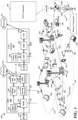
- FIG. 1 is a diagram illustrating an example of a wireless communications system and an access network 100.
- the wireless communications system (also referred to as a wireless wide area network (WWAN)) includes base stations 102, UEs 104, an Evolved Packet Core (EPC) 160, and another core network 190 (e.g., a 5G Core (5GC)).
- the base stations 102 may include macrocells (high power cellular base station) and/or small cells (low power cellular base station).
- the macrocells include base stations.
- the small cells include femtocells, picocells, and microcells.
- the base stations 102 configured for 4G LTE may interface with the EPC 160 through backhaul links 132 (e.g., S1 interface).
- the base stations 102 configured for 5GNR may interface with core network 190 through backhaul links 184.
- UMTS Universal Mobile Telecommunications System
- 5GNR Next Generation RAN
- the base stations 102 may perform one or more of the following functions: transfer of user data, radio channel ciphering and deciphering, integrity protection, header compression, mobility control functions (e.g., handover, dual connectivity), inter-cell interference coordination, connection setup and release, load balancing, distribution for non-access stratum (NAS) messages, NAS node selection, synchronization, radio access network (RAN) sharing, multimedia broadcast multicast service (MBMS), subscriber and equipment trace, RAN information management (RIM), paging, positioning, and delivery of warning messages.
- the base stations 102 may communicate directly or indirectly (e.g., through the EPC 160 or core network 190) with each other over backhaul links 134 (e.g., X2 interface).
- the backhaul links 134 may be wired or wireless.
- the base stations 102 may wirelessly communicate with the UEs 104. Each of the base stations 102 may provide communication coverage for a respective geographic coverage area 110. There may be overlapping geographic coverage areas 110. For example, the small cell 102' may have a coverage area 110' that overlaps the coverage area 110 of one or more macro base stations 102.
- a network that includes both small cell and macrocells may be known as a heterogeneous network.
- a heterogeneous network may also include Home Evolved Node Bs (eNBs) (HeNBs), which may provide service to a restricted group known as a closed subscriber group (CSG).
- eNBs Home Evolved Node Bs
- CSG closed subscriber group
- the communication links 120 between the base stations 102 and the UEs 104 may include uplink (UL) (also referred to as reverse link) transmissions from a UE 104 to a base station 102 and/or downlink (DL) (also referred to as forward link) transmissions from a base station 102 to a UE 104.
- the communication links 120 may use multiple-input and multiple-output (MIMO) antenna technology, including spatial multiplexing, beamforming, and/or transmit diversity.
- the communication links may be through one or more carriers.
- the base stations 102 / UEs 104 may use spectrum up to Y MHz (e.g., 5, 10, 15, 20, 100, 400, etc.
- the component carriers may include a primary component carrier and one or more secondary component carriers.
- a primary component carrier may be referred to as a primary cell (PCell) and a secondary component carrier may be referred to as a secondary cell (SCell).
- D2D communication link 158 may use the DL/UL WWAN spectrum.
- the D2D communication link 158 may use one or more sidelink channels, such as a physical sidelink broadcast channel (PSBCH), a physical sidelink discovery channel (PSDCH), a physical sidelink shared channel (PSSCH), and a physical sidelink control channel (PSCCH).
- sidelink channels such as a physical sidelink broadcast channel (PSBCH), a physical sidelink discovery channel (PSDCH), a physical sidelink shared channel (PSSCH), and a physical sidelink control channel (PSCCH).
- sidelink channels such as a physical sidelink broadcast channel (PSBCH), a physical sidelink discovery channel (PSDCH), a physical sidelink shared channel (PSSCH), and a physical sidelink control channel (PSCCH).
- sidelink channels such as a physical sidelink broadcast channel (PSBCH), a physical sidelink discovery channel (PSDCH), a physical sidelink shared channel (PSSCH), and a physical sidelink control channel (PSCCH).
- the wireless communications system may further include a Wi-Fi access point (AP) 150 in communication with Wi-Fi stations (STAs) 152 via communication links 154 in a 5 GHz unlicensed frequency spectrum.
- AP Wi-Fi access point
- STAs Wi-Fi stations
- communication links 154 in a 5 GHz unlicensed frequency spectrum.
- the STAs 152 / AP 150 may perform a clear channel assessment (CCA) prior to communicating in order to determine whether the channel is available.
- CCA clear channel assessment
- the small cell 102' may operate in a licensed and/or an unlicensed frequency spectrum. When operating in an unlicensed frequency spectrum, the small cell 102' may employ NR and use the same 5 GHz unlicensed frequency spectrum as used by the Wi-Fi AP 150. The small cell 102', employing NR in an unlicensed frequency spectrum, may boost coverage to and/or increase capacity of the access network.
- a base station 102 may include an eNB, gNodeB (gNB), or another type of base station.
- Some base stations, such as gNB 180 may operate in a traditional sub 6 GHz spectrum, in millimeter wave (mmW) frequencies, and/or near mmW frequencies in communication with the UE 104.
- mmW millimeter wave
- mmW base station When the gNB 180 operates in mmW or near mmW frequencies, the gNB 180 may be referred to as an mmW base station.
- Extremely high frequency (EHF) is part of the RF in the electromagnetic spectrum. EHF has a range of 30 GHz to 300 GHz and a wavelength between 1 millimeter and 10 millimeters.
- Radio waves in the band may be referred to as a millimeter wave.
- Near mmW may extend down to a frequency of 3 GHz with a wavelength of 100 millimeters.
- the super high frequency (SHF) band extends between 3 GHz and 30 GHz, also referred to as centimeter wave.
- Communications using the mmW / near mmW radio frequency band (e.g., 3 GHz - 300 GHz) has extremely high path loss and a short range.
- the mmW base station 180 may utilize beamforming 182 with the UE 104 to compensate for the extremely high path loss and short range.
- the base station 180 may transmit a beamformed signal to the UE 104 in one or more transmit directions 182'.
- the UE 104 may receive the beamformed signal from the base station 180 in one or more receive directions 182".
- the UE 104 may also transmit a beamformed signal to the base station 180 in one or more transmit directions.
- the base station 180 may receive the beamformed signal from the UE 104 in one or more receive directions.
- the base station 180 / UE 104 may perform beam training to determine the best receive and transmit directions for each of the base station 180 / UE 104.
- the transmit and receive directions for the base station 180 may or may not be the same.
- the transmit and receive directions for the UE 104 may or may not be the same.
- the EPC 160 may include a Mobility Management Entity (MME) 162, other MMEs 164, a Serving Gateway 166, a Multimedia Broadcast Multicast Service (MBMS) Gateway 168, a Broadcast Multicast Service Center (BM-SC) 170, and a Packet Data Network (PDN) Gateway 172.
- MME Mobility Management Entity
- MBMS Multimedia Broadcast Multicast Service
- BM-SC Broadcast Multicast Service Center
- PDN Packet Data Network
- the MME 162 may be in communication with a Home Subscriber Server (HSS) 174.
- HSS Home Subscriber Server
- the MME 162 is the control node that processes the signaling between the UEs 104 and the EPC 160.
- the MME 162 provides bearer and connection management. All user Internet protocol (IP) packets are transferred through the Serving Gateway 166, which itself is connected to the PDN Gateway 172.
- IP Internet protocol
- the PDN Gateway 172 provides UE IP address allocation as well as other functions.
- the PDN Gateway 172 and the BM-SC 170 are connected to the IP Services 176.
- the IP Services 176 may include the Internet, an intranet, an IP Multimedia Subsystem (IMS), a PS Streaming Service, and/or other IP services.
- the BM-SC 170 may provide functions for MBMS user service provisioning and delivery.
- the BM-SC 170 may serve as an entry point for content provider MBMS transmission, may be used to authorize and initiate MBMS Bearer Services within a public land mobile network (PLMN), and may be used to schedule MBMS transmissions.
- PLMN public land mobile network
- the MBMS Gateway 168 may be used to distribute MBMS traffic to the base stations 102 belonging to a Multicast Broadcast Single Frequency Network (MBSFN) area broadcasting a particular service, and may be responsible for session management (start/stop) and for collecting eMBMS related charging information.
- MMSFN Multicast Broadcast Single Frequency Network
- the core network 190 may include a Access and Mobility Management Function (AMF) 192, other AMFs 193, a Session Management Function (SMF) 194, and a User Plane Function (UPF) 195.
- the AMF 192 may be in communication with a Unified Data Management (UDM) 196.
- the AMF 192 is the control node that processes the signaling between the UEs 104 and the core network 190.
- the AMF 192 provides QoS flow and session management. All user Internet protocol (IP) packets are transferred through the UPF 195.
- the UPF 195 provides UE IP address allocation as well as other functions.
- the UPF 195 is connected to the IP Services 197.
- the IP Services 197 may include the Internet, an intranet, an IP Multimedia Subsystem (IMS), a PS Streaming Service, and/or other IP services.
- IMS IP Multimedia Subsystem
- the base station may also be referred to as a gNB, Node B, evolved Node B (eNB), an access point, a base transceiver station, a radio base station, a radio transceiver, a transceiver function, a basic service set (BSS), an extended service set (ESS), a transmit reception point (TRP), or some other suitable terminology.
- the base station 102 provides an access point to the EPC 160 or core network 190 for a UE 104.
- Examples of UEs 104 include a cellular phone, a smart phone, a session initiation protocol (SIP) phone, a laptop, a personal digital assistant (PDA), a satellite radio, a global positioning system, a multimedia device, a video device, a digital audio player (e.g., MP3 player), a camera, a game console, a tablet, a smart device, a wearable device, a vehicle, an electric meter, a gas pump, a large or small kitchen appliance, a healthcare device, an implant, a sensor/actuator, a display, or any other similar functioning device.
- SIP session initiation protocol
- PDA personal digital assistant
- the UEs 104 may be referred to as IoT devices (e.g., parking meter, gas pump, toaster, vehicles, heart monitor, etc.).
- the UE 104 may also be referred to as a station, a mobile station, a subscriber station, a mobile unit, a subscriber unit, a wireless unit, a remote unit, a mobile device, a wireless device, a wireless communications device, a remote device, a mobile subscriber station, an access terminal, a mobile terminal, a wireless terminal, a remote terminal, a handset, a user agent, a mobile client, a client, or some other suitable terminology.
- the UE 104 may be configured to monitor for a group WUS at a determined location.
- the UE 104 of FIG. 1 may include a monitor component 198 configured to monitor for a group WUS at a determined location in an allocation of resources.
- the UE 104 may receive, from a base station, the allocation of resources assigned to noe or more UEs in a UE group, the allocation of resources comprising a group WUS resource.
- the UE 104 may determine a location of the group WUS resource within a set of WUS resources associated with a paging occasion.
- the base station 102/180 may be configured to transmit a group WUS resource.
- the base station 102/180 of FIG. 1 may include a WUS component 199 configured to transmit, to one or more UEs in a UE group, an allocation of resources assigned to the one or more UEs in the UE group, the allocation of resources comprising a group WUS resource within a set of WUS resources associated with a paging occasion.
- the base station 102/180 may group one or more UEs in the UE group.
- FIG. 2A is a diagram 200 illustrating an example of a first subframe within a 5G/NR frame structure.
- FIG. 2B is a diagram 230 illustrating an example of DL channels within a 5G/NR subframe.
- FIG. 2C is a diagram 250 illustrating an example of a second subframe within a 5G/NR frame structure.
- FIG. 2D is a diagram 280 illustrating an example of UL channels within a 5G/NR subframe.
- the 5G/NR frame structure may be FDD in which for a particular set of subcarriers (carrier system bandwidth), subframes within the set of subcarriers are dedicated for either DL or UL, or may be TDD in which for a particular set of subcarriers (carrier system bandwidth), subframes within the set of subcarriers are dedicated for both DL and UL.
- the 5G/NR frame structure is assumed to be TDD, with subframe 4 being configured with slot format 28 (with mostly DL), where D is DL, U is UL, and X is flexible for use between DL/UL, and subframe 3 being configured with slot format 34 (with mostly UL).
- subframes 3, 4 are shown with slot formats 34, 28, respectively, any particular subframe may be configured with any of the various available slot formats 0-61.
- Slot formats 0, 1 are all DL, UL, respectively.
- Other slot formats 2-61 include a mix of DL, UL, and flexible symbols.
- UEs are configured with the slot format (dynamically through DL control information (DCI), or semi-statically/statically through radio resource control (RRC) signaling) through a received slot format indicator (SFI). Note that the description infra applies also to a 5G/NR frame structure that is TDD.
- DCI DL control information
- RRC radio resource control
- a frame (10 ms) may be divided into 10 equally sized subframes (1 ms). Each subframe may include one or more time slots. Subframes may also include mini-slots, which may include 7, 4, or 2 symbols. Each slot may include 7 or 14 symbols, depending on the slot configuration. For slot configuration 0, each slot may include 14 symbols, and for slot configuration 1, each slot may include 7 symbols.
- the symbols on DL may be cyclic prefix (CP) OFDM (CP-OFDM) symbols.
- the symbols on UL may be CP-OFDM symbols (for high throughput scenarios) or discrete Fourier transform (DFT) spread OFDM (DFT-s-OFDM) symbols (also referred to as single carrier frequency-division multiple access (SC-FDMA) symbols) (for power limited scenarios; limited to a single stream transmission).
- the number of slots within a subframe is based on the slot configuration and the numerology. For slot configuration 0, different numerologies ⁇ 0 to 5 allow for 1, 2, 4, 8, 16, and 32 slots, respectively, per subframe. For slot configuration 1, different numerologies 0 to 2 allow for 2, 4, and 8 slots, respectively, per subframe. Accordingly, for slot configuration 0 and numerology ⁇ , there are 14 symbols/slot and 2 ⁇ slots/subframe.
- the subcarrier spacing and symbol length/duration are a function of the numerology.
- the subcarrier spacing may be equal to 2 ⁇ * 15 kKz, where ⁇ is the numerology 0 to 5.
- ⁇ is the numerology 0 to 5.
- the symbol length/duration is inversely related to the subcarrier spacing.
- the subcarrier spacing is 15 kHz and symbol duration is approximately 66.7 ⁇ s.
- a resource grid may be used to represent the frame structure.
- Each time slot includes a resource block (RB) (also referred to as physical RBs (PRBs)) that extends 12 consecutive subcarriers.
- RB resource block
- PRBs physical RBs
- the resource grid is divided into multiple resource elements (REs). The number of bits carried by each RE depends on the modulation scheme.
- the RS may include demodulation RS (DM-RS) (indicated as R x for one particular configuration, where 100x is the port number, but other DM-RS configurations are possible) and channel state information reference signals (CSI-RS) for channel estimation at the UE.
- DM-RS demodulation RS
- CSI-RS channel state information reference signals
- the RS may also include beam measurement RS (BRS), beam refinement RS (BRRS), and phase tracking RS (PT-RS).
- BRS beam measurement RS
- BRRS beam refinement RS
- PT-RS phase tracking RS
- FIG. 2B illustrates an example of various DL channels within a subframe of a frame.
- the physical downlink control channel (PDCCH) carries DCI within one or more control channel elements (CCEs), each CCE including nine RE groups (REGs), each REG including four consecutive REs in an OFDM symbol.
- a primary synchronization signal (PSS) may be within symbol 2 of particular subframes of a frame. The PSS is used by a UE 104 to determine subframe/symbol timing and a physical layer identity.
- a secondary synchronization signal (SSS) may be within symbol 4 of particular subframes of a frame. The SSS is used by a UE to determine a physical layer cell identity group number and radio frame timing.
- the UE can determine a physical cell identifier (PCI). Based on the PCI, the UE can determine the locations of the aforementioned DM-RS.
- the physical broadcast channel (PBCH) which carries a master information block (MIB), may be logically grouped with the PSS and SSS to form a synchronization signal (SS)/PBCH block.
- the MIB provides a number of RBs in the system bandwidth and a system frame number (SFN).
- the physical downlink shared channel (PDSCH) carries user data, broadcast system information not transmitted through the PBCH such as system information blocks (SIBs), and paging messages.
- SIBs system information blocks
- some of the REs carry DM-RS (indicated as R for one particular configuration, but other DM-RS configurations are possible) for channel estimation at the base station.
- the UE may transmit DM-RS for the physical uplink control channel (PUCCH) and DM-RS for the physical uplink shared channel (PUSCH).
- the PUSCH DM-RS may be transmitted in the first one or two symbols of the PUSCH.
- the PUCCH DM-RS may be transmitted in different configurations depending on whether short or long PUCCHs are transmitted and depending on the particular PUCCH format used.
- the UE may transmit sounding reference signals (SRS).
- the SRS may be used by a base station for channel quality estimation to enable frequency-dependent scheduling on the UL.
- FIG. 2D illustrates an example of various UL channels within a subframe of a frame.
- the PUCCH may be located as indicated in one configuration.
- the PUCCH carries uplink control information (UCI), such as scheduling requests, a channel quality indicator (CQI), a precoding matrix indicator (PMI), a rank indicator (RI), and HARQ ACK/NACK feedback.
- UCI uplink control information
- the PUSCH carries data, and may additionally be used to carry a buffer status report (BSR), a power headroom report (PHR), and/or UCI.
- BSR buffer status report
- PHR power headroom report
- FIG. 3 is a block diagram of a base station 310 in communication with a UE 350 in an access network.
- IP packets from the EPC 160 may be provided to a controller/processor 375.
- the controller/processor 375 implements layer 3 and layer 2 functionality.
- Layer 3 includes a radio resource control (RRC) layer
- layer 2 includes a service data adaptation protocol (SDAP) layer, a packet data convergence protocol (PDCP) layer, a radio link control (RLC) layer, and a medium access control (MAC) layer.
- RRC radio resource control
- SDAP service data adaptation protocol
- PDCP packet data convergence protocol
- RLC radio link control
- MAC medium access control
- the controller/processor 375 provides RRC layer functionality associated with broadcasting of system information (e.g., MIB, SIBs), RRC connection control (e.g., RRC connection paging, RRC connection establishment, RRC connection modification, and RRC connection release), inter radio access technology (RAT) mobility, and measurement configuration for UE measurement reporting; PDCP layer functionality associated with header compression / decompression, security (ciphering, deciphering, integrity protection, integrity verification), and handover support functions; RLC layer functionality associated with the transfer of upper layer packet data units (PDUs), error correction through ARQ, concatenation, segmentation, and reassembly of RLC service data units (SDUs), re-segmentation of RLC data PDUs, and reordering of RLC data PDUs; and MAC layer functionality associated with mapping between logical channels and transport channels, multiplexing of MAC SDUs onto transport blocks (TBs), demultiplexing of MAC SDUs from TBs, scheduling information reporting, error correction
- the transmit (TX) processor 316 and the receive (RX) processor 370 implement layer 1 functionality associated with various signal processing functions.
- Layer 1 which includes a physical (PHY) layer, may include error detection on the transport channels, forward error correction (FEC) coding/decoding of the transport channels, interleaving, rate matching, mapping onto physical channels, modulation/demodulation of physical channels, and MIMO antenna processing.
- the TX processor 316 handles mapping to signal constellations based on various modulation schemes (e.g., binary phase-shift keying (BPSK), quadrature phase-shift keying (QPSK), M-phase-shift keying (M-PSK), M-quadrature amplitude modulation (M-QAM)).
- BPSK binary phase-shift keying
- QPSK quadrature phase-shift keying
- M-PSK M-phase-shift keying
- M-QAM M-quadrature amplitude modulation
- Each stream may then be mapped to an OFDM subcarrier, multiplexed with a reference signal (e.g., pilot) in the time and/or frequency domain, and then combined together using an Inverse Fast Fourier Transform (IFFT) to produce a physical channel carrying a time domain OFDM symbol stream.
- the OFDM stream is spatially precoded to produce multiple spatial streams.
- Channel estimates from a channel estimator 374 may be used to determine the coding and modulation scheme, as well as for spatial processing.
- the channel estimate may be derived from a reference signal and/or channel condition feedback transmitted by the UE 350.
- Each spatial stream may then be provided to a different antenna 320 via a separate transmitter 318TX.
- Each transmitter 318TX may modulate an RF carrier with a respective spatial stream for transmission.
- each receiver 354RX receives a signal through its respective antenna 352.
- Each receiver 354RX recovers information modulated onto an RF carrier and provides the information to the receive (RX) processor 356.
- the TX processor 368 and the RX processor 356 implement layer 1 functionality associated with various signal processing functions.
- the RX processor 356 may perform spatial processing on the information to recover any spatial streams destined for the UE 350. If multiple spatial streams are destined for the UE 350, they may be combined by the RX processor 356 into a single OFDM symbol stream.
- the RX processor 356 then converts the OFDM symbol stream from the time-domain to the frequency domain using a Fast Fourier Transform (FFT).
- FFT Fast Fourier Transform
- the frequency domain signal comprises a separate OFDM symbol stream for each subcarrier of the OFDM signal.
- the symbols on each subcarrier, and the reference signal are recovered and demodulated by determining the most likely signal constellation points transmitted by the base station 310. These soft decisions may be based on channel estimates computed by the channel estimator 358.
- the soft decisions are then decoded and deinterleaved to recover the data and control signals that were originally transmitted by the base station 310 on the physical channel.
- the data and control signals are then provided to the controller/processor 359, which implements layer 3 and layer 2 functionality.
- the controller/processor 359 can be associated with a memory 360 that stores program codes and data.
- the memory 360 may be referred to as a computer-readable medium.
- the controller/processor 359 provides demultiplexing between transport and logical channels, packet reassembly, deciphering, header decompression, and control signal processing to recover IP packets from the EPC 160.
- the controller/processor 359 is also responsible for error detection using an ACK and/or NACK protocol to support HARQ operations.
- the controller/processor 359 provides RRC layer functionality associated with system information (e.g., MIB, SIBs) acquisition, RRC connections, and measurement reporting; PDCP layer functionality associated with header compression / decompression, and security (ciphering, deciphering, integrity protection, integrity verification); RLC layer functionality associated with the transfer of upper layer PDUs, error correction through ARQ, concatenation, segmentation, and reassembly of RLC SDUs, re-segmentation of RLC data PDUs, and reordering of RLC data PDUs; and MAC layer functionality associated with mapping between logical channels and transport channels, multiplexing of MAC SDUs onto TBs, demultiplexing of MAC SDUs from TBs, scheduling information reporting, error correction through HARQ, priority handling, and logical channel prioritization.
- RRC layer functionality associated with system information (e.g., MIB, SIBs) acquisition, RRC connections, and measurement reporting
- PDCP layer functionality associated with header compression
- Channel estimates derived by a channel estimator 358 from a reference signal or feedback transmitted by the base station 310 may be used by the TX processor 368 to select the appropriate coding and modulation schemes, and to facilitate spatial processing.
- the spatial streams generated by the TX processor 368 may be provided to different antenna 352 via separate transmitters 354TX. Each transmitter 354TX may modulate an RF carrier with a respective spatial stream for transmission.
- the UL transmission is processed at the base station 310 in a manner similar to that described in connection with the receiver function at the UE 350.
- Each receiver 318RX receives a signal through its respective antenna 320.
- Each receiver 318RX recovers information modulated onto an RF carrier and provides the information to a RX processor 370.
- the controller/processor 375 can be associated with a memory 376 that stores program codes and data.
- the memory 376 may be referred to as a computer-readable medium.
- the controller/processor 375 provides demultiplexing between transport and logical channels, packet reassembly, deciphering, header decompression, control signal processing to recover IP packets from the UE 350. IP packets from the controller/processor 375 may be provided to the EPC 160.
- the controller/processor 375 is also responsible for error detection using an ACK and/or NACK protocol to support HARQ operations.
- At least one of the TX processor 368, the RX processor 356, and the controller/processor 359 may be configured to perform aspects in connection with 198 of FIG. 1 .
- At least one of the TX processor 316, the RX processor 370, and the controller/processor 375 may be configured to perform aspects in connection with 199 of FIG. 1 .
- a UE may be configured for discontinuous reception (DRX).
- the UE may monitor for a page from the base station in order to determine whether to wake up to receiving communication from the base station.
- a wake-up signal WUS
- WUS can be sent from a base station to a UE in order to provide notification of an upcoming paging occasion (PO).
- PO paging occasion
- UEs may be configured for a group WUS.
- a base station can group a plurality of UEs into one or more UE groups and may transmit a group WUS to a particular group of UEs.
- the base station may be able to assign a UE group identification or a group WUS sequence to the UE group. Grouping the UEs allows the base station to transmit a WUS to a specific set of UEs within a particular UE group, instead of transmitting the WUS to all UEs served by the base station. Grouping the UEs allows the base station to determine and transmit a WUS identifying which UEs within the UE group should wake-up for a paging occasion (PO). Prior to receiving the transmission, the UEs can listen for the WUS.
- PO paging occasion
- Each WUS may have a duration that is limited to avoid exceeding a maximum allowed WUS duration. Additionally, a gap period may be provided between the end of the WUS and the PO.
- the base station can also determine the total number of different UE groups, wherein each UE is assigned to a particular group. Within each group, there can be group-capable or grouped UEs and/or ungrouped UEs.
- the ungrouped UEs may be UEs that do not support a group WUS or is not assigned to a group WUS.
- An ungrouped WUS may be referred to as a legacy WUS.
- the grouped UEs may be UE that are capable of being assigned to a UE group, while the legacy or ungrouped UEs may not be capable of being assigned to a UE group.
- each ungrouped UE can receive the same WUS, e.g., an ungrouped WUS, and each grouped UE can receive a group WUS that targets the particular group or sub-group for that UE, e.g., a group-specific WUS.
- the ungrouped WUS can identify which ungrouped UEs should wake-up for an ungrouped PO.
- the group WUS can identify which grouped UEs should wake-up for a group-specific PO.
- up to two time-multiplexed WUS resources for both the ungrouped WUS and the group WUS, may be configured.
- the first implementation may be applied for communication based on NB-IoT as well as other types of wireless communication.
- the location of a group WUS may be determined in relation to the ungrouped WUS.
- the group WUS resource may be configured to coincide with the ungrouped WUS resource or to occur immediately before the ungrouped WUS resource.
- the first group WUS resource may coincide with the ungrouped WUS resource and the second group WUS resource may occur immediately before the first group WUS resource.
- the ungrouped WUS and group WUS may be configured simultaneously to have up to 4 orthogonal WUS resources including the ungrouped WUS resources.
- the second implementation may be employed, for example, for machine type communication (MTC) as well as other types of wireless communication.
- MTC machine type communication
- Up to 2 orthogonal resources including the ungrouped WUS resource may be configured in the time domain, while up to 2 orthogonal resources may be configured in the frequency domain. In some instances, the two orthogonal resources do not necessarily include the ungrouped WUS resource.
- An ungrouped WUS and a group WUS may be configured on the same ungrouped WUS resource based on system information. If a group WUS is configured to share WUS resources with a non-group WUS, a common WUS that is common for all of the groups of UEs may be configured to be a non-group WUS or a legacy WUS. The common WUS may also be configured to be a group WUS that is common to all UE groups, and therefore may not be considered a legacy WUS.
- the group WUS may use the same gap configurations as the ungrouped WUS, with the exception of differences from possible TDM. The use of the same gap period in time may help to avoid additional signaling for a separate gap configuration.
- a UE may assume that a transmit power for a group WUS and an ungrouped WUS is the same.
- the base station may set a power offset for both the grouped and ungrouped WUS relative to a reference signal, e.g., WUS energy per resource element (EPRE) relative to cell-specific reference signal (RS) EPRE.
- a maximum WUS duration for the group WUS may be the same as for the ungrouped WUS.
- a UE may detect 2 sequences, the common WUS (that is common to all of the UE groups) and the group WUS associated to the group to which the UE belongs.
- Different WUS resources may use different scrambling sequences by using different initialization seeds, e.g., c_init, or by using different truncated part of a long scrambling sequence with same scrambling seed as that of ungrouped WUS.
- the group WUS may be enabled independently from the ungrouped WUS.
- the group WUS may be enabled without enabling the ungrouped WUS.
- the group WUS and the ungrouped WUS may both be enabled.
- the group WUS configuration may be determined using at least some of the parameters of the ungrouped WUS.
- FIG. 4 illustrates examples 400 of patterns of WUS resources.
- WUS resources that are associated with the same PO and same gap on the same narrow band may be consecutive to each other. This allows for a reduction in peak to average power ration (PAPR) as well as the combinations of the patterns.
- the WUS resources may include the resources used to transmit ungrouped and group WUS sequences.
- the location of the WUS resource (e.g., #0) for ungrouped WUS sequence (e.g., #0) may be used to indicate the location of other WUS resources used to transmit other group WUS sequences.
- Pattern 1 402 may be used if the ungrouped WUS resource #0 is located in the top 2-RB (a first resource block and a second resource block) of a six resource block bandwidth.
- Pattern 1 402 may be used if the ungrouped WUS resource #0 is located in the center 2-RB (a third resource block and a fourth resource block) of the six resource block bandwidth.
- a 1-bit indication may be used to indicate the desired pattern, for example Pattern 2-1 404 or Pattern 2-2 406 may be used.
- one of the Patterns 2-1 or 2-2 may be predefined without additional signaling.
- Pattern 3 408 may be used.
- the WUS resources #1, #2, and #3 may be configured to transmit group WUS sequences, while the WUS resource #0 may be configured to be shared by the ungrouped WUS sequence and group WUS sequences. In aspects where the ungrouped WUS is not configured, then all the WUS resources are used to transmit group WUS sequences.
- a 2-bit indication may be used to indicate the WUS resource #0 frequency position, such as the top, center or bottom 2-PRB in the six-RB bandwidth, which also implicitly indicated the Pattern 1, 2-1 or 3 based on the indicated location of WUS resource #0, respectively; while in some aspects, a 2-bit indication may be used to directly indicate Patterns 1, 2-1, 2-2, or 3.
- the location of the WUS resources for group WUS may be dependent on the configuration of the ungrouped WUS configuration.
- the ungrouped WUS freqLocation ⁇ n0, n2, or n4 ⁇ can be used to indicate Pattern 1, 2 or 3 implicitly based on the predefined table.
- the location and number of WUS resources may be jointed signaled as WUS resource patterns.
- the WUS resource index increases in frequency first and time second manner relative to the legacy WUS resource (e.g., WUS resource #0 and #1 FDMed in the same time slot, and WUS resource #2 and #3 FDMed in another time slot for MTC).
- the WUS resource location can be selected among Pattern 1, 2 and 3 in Table 1.
- 1bit is introduced to choose Pattern 1 or Pattern 2 considering the similarity of 4-resource location for Pattern 2 and 3 to limit 3 bits in total for WUS resource configuration for group WUS.
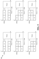
- FIG. 5 illustrates additional examples 500 of patterns of WUS resources.
- the patterns of FIG. 5 include resources that are not consecutive in time and/or frequency.
- the patterns having non-consecutive mapping may allow for scheduling flexibility and may improve frequency diversity in instances where frequency hopping or alternating UE group among different WUS resources is enabled.
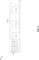
- FIG. 6 illustrates an example 600 of WUS mapping in eDRX mode.
- a UE may be configured by a base station for a DRX mode or eDRX. When there is no data to be transmitted between the UE and base station in either direction, e.g., no uplink or downlink transmissions, the UE may enter the DRX mode or eDRX mode in which the UE may monitor a control channel discontinuously using a sleep and wake cycle.
- eDRX mode is similar to DRX but has longer timer values which allows the UE to remain in a sleep cycle for a longer duration than DRX, which may increase power savings.
- DRX and eDRX may help to conserve battery power at the UE.
- the base station may send a WUS to a UE in advance of a PO when the base station will transmit communication to the UE. If the UE receives a WUS, the UE may wake-up by preparing to receive the communication during the PO. If the UE does not receive a WUS, the UE may return to the sleep mode.
- a UE that supports eDRX with the ungrouped WUS may be configured with the number of POs associated with an ungrouped WUS. Based on the configuration, the UE monitors one WUS that is associated with a group of consecutive POs for power savings. If the UE is configured with a number of POs that is equal to three, the UE will monitor a WUS and will either wake up or remain in a sleep mode for the three POs associated with the WUS based on whether the UE receives the WUS.
- the number of POs may be applied to eDRX UEs to enable the ungrouped and group WUS associated with the same group of consecutive POs on the same narrowband or carriers.
- the number of POs may be configured to enable the group WUS associated with the same group of consecutive POs on the same narrowband or carriers.
- a UE may be configured to alternate between UE groups.
- M 2, 3, 4.
- the UE group(s) may be enabled to monitor the resource with predefined WUS resource index order in different POs.
- Alternating UE groups may be implicitly enabled when M>1 or explicitly enabled by 1bit in SIB per cell-specific, e.g., for MTC group WUS or carrier-specific, e.g., for NB-IoT group WUS.
- the first method includes a change of the resource ID, while keeping the same phase of the WUS sequence, which is based on the group ID in a WUS resource, and does not change the UE groups allocated in one WUS resource. Especially when considering service-based UE grouping, the UE groups with different services have different paging probability. It is more reasonable to use different WUS resources to separate the UE groups with different services to avoid the impact of services with large paging probability on the other services.
- the second method may include a change of the resource ID and phase ID, and changes the min UE groups, which may result in mixed services in same WUS resource.
- the first method may have a potential impact on ungrouped WUS UEs if a larger number of UE groups move into the ungrouped WUS resource and ungrouped WUS as the common WUS will wake up ungrouped and group WUS UEs together.
- the second method may be used to maintain the number of UE groups in one WUS resource.
- using first method or second method may be based on whether ungrouped WUS is configured or not, or ungrouped WUS is configured as common WUS for group WUS in the WUS resource#0 or not. For example, if ungrouped WUS is not configured as common WUS for group WUS in the WUS resource#0, the first method is used; otherwise, the second method is used. In some aspects, using the first method or second method may be based on whether service-based UE grouping is used for group WUS or not. For example, if service-based UE grouping is used for group WUS, the first method is used; otherwise, the second method is used.
- M 2
- m-WUS resource monitored at i-th PO i 0 1 2 3 4 5 6 7
- all UE groups may be alternated in the same WUS resource together such that only the scrambling sequence (e.g., ⁇ 1, -1, j, -j ⁇ ) is changed based on the monitored WUS resource index, while keeping the phase shift, which is based on the group ID in the WUS resource, for the group WUS sequence the same.
- the resources #0 and #1 may be used for alternating the UE group.
- the legacy WUS sequence is not configured as a common WUS sequence, then there is no impact.
- legacy WUS sequence is configured as a common WUS sequence
- the changing (e.g., alternating or hopping) of the monitored WUS resource per PO may reduce the probability of such an occurrence.
- the UE groups may only alternate between #1, #2, or #3.
- service-based grouping is used for group WUS. Assuming there are S types of services (each service associated to a subset of groups), it would be better to alternate the UE groups that belong to the same service type s (e.g., with similar paging probability) among the corresponding WUS resources, while not alternating the UE groups with different services. In some aspects, all of the UE groups per WUS resource may belong to the same service type s. There may be more than one WUS resource that belongs to the same service type s.
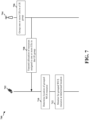
- FIG. 7 is a diagram 700 illustrating transmission between a base station and a UE.
- the diagram 700 includes a UE 702 and a base station 704.
- the base station 704, at 706, may group one or more UEs in a UE group.
- the base station 704 may transmit, to one or more UEs in the UE group, an allocation of resources assigned to the one or more UEs in the UE group.
- the allocation of resources may comprise a group WUS resource within a set of WUS resources associated with a PO.
- the set of WUS resources may include a ungrouped WUS, where the location of the group WUS may be based on a frequency location of the ungrouped WUS.
- the location of the group WUS resource may be based on at least one of the ungrouped WUS having the frequency location in a first resource block and a second resource block of a six resource block bandwidth, the ungrouped WUS having the frequency location in a third resource block and a fourth resource block of the six resource block bandwidth, or the ungrouped WUS having the frequency location in a fifth resource block and a sixth resource block of the six resource block bandwidth.
- the set of WUS resources may not include an ungrouped WUS. In such instances, the location of the group WUS resource may be based on information indicated in a configuration for the group WUS.
- the set of WUS resources may be consecutive in time and frequency. In some aspects, the set of WUS resources may be non-consecutive in time or frequency.
- the UE 702, at 710, may determine a location of the group WUS resource within a set of WUS resources.
- the set of WUS resources may be associated with a paging occasion.
- the set of WUS resources may include an ungrouped WUS.
- the location of the group WUS resource may be determined based on a frequency location of the ungrouped WUS.
- the UE 702, at 712, may monitor for a group WUS at the determined location in the allocation of resources.
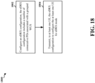
- FIG. 8 is a diagram 800 illustrating transmission between a base station and a UE.
- the diagram 800 includes a UE 802 and a base station 804.
- the base station 804, at 806, may configure an eDRX configuration.
- the eDRX configuration may include a number of consecutive POs associated with a group WUS.
- the eDRX configuration may include a configured number of consecutive POs associated with an ungrouped WUS.
- the number of consecutive POs associated with the group WUS may be based on the configured number of consecutive POs associated with the ungrouped WUS.
- the eDRX configuration may indicate the number of consecutive POs associated for the group WUS.
- the base station 804, at 808, may transmit the eDRX configuration to at least one UE.
- the eDRX configuration may configure the at least one UE for eDRX mode.
- the UE 802 after receiving the eDRX configuration, UE may determine, at 810, a number of consecutive POs associated with a group WUS.
- the eDRX configuration may indicate the number of consecutive POs associated for the group WUS.
- the UE 802, at 812, may monitor for the group WUS while in eDRX mode based on the determined number of consecutive POs.
- the eDRX configuration may include a configured number of consecutive POs associated with an ungrouped WUS.
- the UE may determine the number of consecutive POs associated with the group WUS based on the configured number of consecutive POs associated with the ungrouped WUS.
- FIG. 9 is a diagram 900 illustrating transmission between a base station and a UE.
- the diagram 900 includes a UE 902 and a base station 904.
- the base station 904, at 906, may configure an allocation of resources for a group WUS associated with one or more UEs in a UE group.
- a first WUS resource of M WUS resources may be associated with a first PO.
- a second WUS resource of M WUS resources may be associated with a second PO.
- a same WUS sequence may be allocated for the UE group to monitor any of the M WUS resources.
- the base station 904, at 908, may apply a WUS sequence to the M WUS resources associated with the respective one of the first or second WUS resources.
- the WUS sequence may further include a scrambling sequence associated with the respective one of the first or second WUS resources.
- the base station 904, at 910, may transmit the group WUS to the one or more UEs in the UE group.
- the base station may transmit the group WUS associated with the one or more UEs at different POs using a pattern associated with a location of the M WUS resources.
- the UE 902, at 912, may monitor for the WUS at a first WUS resource of M WUS resources for a first paging opportunity.
- the UE 902, at 914, may monitor for the WUS at a second WUS resource of M WUS resources for a second paging opportunity.
- the UE may monitor for the WUS at different POs using a pattern associated with a location of the M WUS resources.
- the pattern associated with the M WUS resources may be determined at least based on a discontinuous reception cycle indicated in system information.
- a same WUS sequence may be allocated for the UE group to monitor any of the M WUS resources.
- the UE 902, at 916 may use a WUS sequence associated with the respective one of the first or second WUS resources.
- the WUS sequence may further include a scrambling sequence associated with the respective one of the first or second WUS resources.
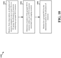
- FIG. 10 is a flowchart of a method 1000 of wireless communication.
- the method may be performed by a UE or a component of a UE (e.g., the UE 104, 350, 702, 802, 902, which may include the memory 360 and which may be the entire UE 350 or a component of the UE 350, such as the TX processor 368, the RX processor 356, and/or the controller/processor 359).
- one or more of the illustrated operations of the method 1000 may be omitted, transposed, and/or contemporaneously performed.
- the method may enable a UE to monitor for a group WUS at a determined location within an allocation of resources.
- the UE may receive an allocation of resources assigned to one or more UEs in a UE group.
- the allocation of resources may comprise a group WUS resource.
- the UE may receive the allocation of resources from a base station.
- the UE may determine a location of the group WUS resource within a set of WUS resources.
- the set of WUS resources may be associated with a paging occasion.
- the set of WUS resources may include an ungrouped WUS.
- the location of the group WUS resource may be determined based on a frequency location of the ungrouped WUS.
- the location of the group WUS resource is determined based on the ungrouped WUS having the frequency location in a first resource block and a second resource block of a six resource block bandwidth.
- the location of the group WUS resource may be determined based on the ungrouped WUS having the frequency location in a third resource block and a fourth resource block of the six resource block bandwidth.
- the location of the group WUS resource may be determined based on the ungrouped WUS having the frequency location in a fifth resource block and a sixth resource block of the six resource block bandwidth. In some aspects, the location of the group WUS resource may be determined based on at least one of the ungrouped WUS having the frequency location in a first resource block and a second resource block of a six resource block bandwidth, the ungrouped WUS having the frequency location in a third resource block and a fourth resource block of the six resource block bandwidth, or the ungrouped WUS having the frequency location in a fifth resource block and a sixth resource block of the six resource block bandwidth.
- the set of WUS resources may not include an ungrouped WUS, such that the location of the group WUS resource may be determined based on information indicated in a configuration for the group WUS.
- the set of WUS resources may be consecutive in time and frequency, e.g., for example, as shown in FIG. 4 .
- the set of WUS resources may be non-consecutive in time or frequency, e.g., for example, as shown in FIG. 5 .
- the UE may monitor for a group WUS at the determined location in the allocation of resources.
- FIG. 11 is a diagram 1100 illustrating an example of a hardware implementation for an apparatus 1102.
- the apparatus 1102 is a UE and includes a cellular baseband processor 1104 (also referred to as a modem) coupled to a cellular RF transceiver 1122 and one or more subscriber identity modules (SIM) cards 1120, an application processor 1106 coupled to a secure digital (SD) card 1108 and a screen 1110, a Bluetooth module 1112, a wireless local area network (WLAN) module 1114, a Global Positioning System (GPS) module 1116, and a power supply 1118.
- the cellular baseband processor 1104 communicates through the cellular RF transceiver 1122 with the UE 104 and/or BS 102/180.
- the cellular baseband processor 1104 may include a computer-readable medium / memory.
- the computer-readable medium / memory may be non-transitory.
- the cellular baseband processor 1104 is responsible for general processing, including the execution of software stored on the computer-readable medium / memory.
- the software when executed by the cellular baseband processor 1104, causes the cellular baseband processor 1104 to perform the various functions described supra.
- the computer-readable medium / memory may also be used for storing data that is manipulated by the cellular baseband processor 1104 when executing software.
- the cellular baseband processor 1104 further includes a reception component 1130, a communication manager 1132, and a transmission component 1134.
- the communication manager 1132 includes the one or more illustrated components.
- the components within the communication manager 1132 may be stored in the computer-readable medium / memory and/or configured as hardware within the cellular baseband processor 1104.
- the cellular baseband processor 1104 may be a component of the UE 350 and may include the memory 360 and/or at least one of the TX processor 368, the RX processor 356, and the controller/processor 359.
- the apparatus 1102 may be a modem chip and include just the baseband processor 1104, and in another configuration, the apparatus 1102 may be the entire UE (e.g., see 350 of FIG. 3 ) and include the aforementioned additional modules of the apparatus 1102.
- the reception component 1130 is configured to receive, from a base station (e.g., 102/180), an allocation of resources assigned to one or more UEs in a UE group, in which the allocation of resources includes a group WUS resource.
- the communication manager 1132 includes a determination component 1140 that is configured to determine a location of the group WUS resource within a set of WUS resources associated with a paging occasion, e.g., as described in connection with block 1004 of the method 1000 of FIG. 10 .
- the communication manager 1132 further includes a monitoring component 1142 that receives input in the form of the determined location from the determination component 1140 and is configured to monitor for a group WUS at the determined location in the allocation of resources, e.g., as described in connection with block 1006 of the method 1000 of FIG. 10 .
- the apparatus may include additional components that perform each of the blocks of the algorithm in the aforementioned flowchart of FIG. 10 .
- each block in the aforementioned flowcharts of FIG. 10 may be performed by a component and the apparatus may include one or more of those components.
- the components may be one or more hardware components specifically configured to carry out the stated processes/algorithm, implemented by a processor configured to perform the stated processes/algorithm, stored within a computer-readable medium for implementation by a processor, or some combination thereof.
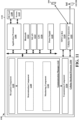
- the UE may receive an eDRX configuration.
- the eDRX configuration may configure the UE for eDRX mode.
- the UE may receive the eDRX configuration from the base station.
- the UE may determine a number of consecutive POs associated with a group WUS.
- the eDRX configuration may indicate the number of consecutive POs associated for the group WUS.
- the reception component 1330 is configured to receive, from a base station (e.g., 102/180), an eDRX configuration that configures the UE for an eDRX mode, e.g., as described in connection with block 1202 of the method 1200 of FIG. 12 .
- the communication manager 1332 includes a determination component 1340 that is configured to determine a number of consecutive POs associated with a group WUS, e.g., as described in connection with block 1204 of the method 1200 of FIG. 12 .
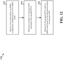
- the UE may monitor for the WUS at a second WUS resource of M WUS resources for a second paging opportunity.
- the UE may monitor for the WUS at different POs using a pattern associated with a location of the M WUS resources.
- the pattern associated with the M WUS resources may be determined at least based on a discontinuous reception cycle indicated in system information.
- a same WUS sequence may be allocated for the UE group to monitor any of the M WUS resources.
- the UE may use a WUS sequence associated with the respective one of the first WUS resource or the second WUS resource.
- the WUS sequence may further include a scrambling sequence associated with the respective one of the first WUS resource or the second WUS resource.
- the scrambling sequence may be based on the first WUS resource or the second WUS resource that is used for the WUS.
- the WUS sequence may further include a phase shift.
- the phase shift may be based on the UE group. In some aspects, the phase shift may be the same if the first WUS resource or the second WUS resource is used for the WUS.
- the UE may monitor for a common WUS sequence.
- the common WUS sequence may be based on the first WUS resource or the second WUS resource that is used to monitor for the WUS.
- the one or more UEs in the UE group may be configured to alternate between the first WUS resource and M-1 WUS resources.
- the one or more UEs in the UE group may alternate between the first WUS resource and M-1 WUS resources if the first WUS resource is allocated for the group WUS.
- the one or more UEs in the UE group may be configured to alternate between the second WUS resource and M WUS resources when the first WUS resource is not allocated for the group WUS.
- the one or more UEs in the UE group may be configured to determine whether to alternate between WUS resources based on an amount of the M WUS resources.
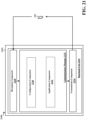
- FIG. 15 is a diagram 1500 illustrating an example of a hardware implementation for an apparatus 1502.
- the apparatus 1502 is a UE and includes a cellular baseband processor 1504 (also referred to as a modem) coupled to a cellular RF transceiver 1522 and one or more subscriber identity modules (SIM) cards 1520, an application processor 1506 coupled to a secure digital (SD) card 1508 and a screen 1510, a Bluetooth module 1512, a wireless local area network (WLAN) module 1514, a Global Positioning System (GPS) module 1516, and a power supply 1518.
- the cellular baseband processor 1504 communicates through the cellular RF transceiver 1522 with the UE 104 and/or BS 102/180.
- the cellular baseband processor 1504 may include a computer-readable medium / memory.
- the computer-readable medium / memory may be non-transitory.
- the cellular baseband processor 1504 is responsible for general processing, including the execution of software stored on the computer-readable medium / memory.
- the software when executed by the cellular baseband processor 1504, causes the cellular baseband processor 1504 to perform the various functions described supra.
- the computer-readable medium / memory may also be used for storing data that is manipulated by the cellular baseband processor 1504 when executing software.
- the cellular baseband processor 1504 further includes a reception component 1530, a communication manager 1532, and a transmission component 1534.
- the communication manager 1532 includes the one or more illustrated components.
- the components within the communication manager 1532 may be stored in the computer-readable medium / memory and/or configured as hardware within the cellular baseband processor 1504.
- the cellular baseband processor 1504 may be a component of the UE 350 and may include the memory 360 and/or at least one of the TX processor 368, the RX processor 356, and the controller/processor 359.
- the apparatus 1502 may be a modem chip and include just the baseband processor 1504, and in another configuration, the apparatus 1502 may be the entire UE (e.g., see 350 of FIG. 3 ) and include the aforementioned additional modules of the apparatus 1502.
- the reception component 1530 is configured to receive, from a base station (e.g., 102/180), an allocation of resources for a group WUS associated with one or more UEs in a UE group, e.g., as described in connection with block 1402 of the method 1400 of FIG. 14 .
- the communication manager 1532 includes a monitoring component 1542 that receives input in the form of the allocation of resources from the reception component 1530 and is configured to monitor for the group WUS at a first WUS resource of M WUS resources for a first PO, e.g., as described in connection with block 1404 of the method 1400 of FIG. 14 .
- the monitoring component 1542 is further configured to monitor for the group WUS at a second WUS resource of M WUS resources for a second PO, e.g., as described in connection with block 1406 of the method 1400 of FIG. 14 .
- the communication manager 1532 further includes a utilization component 1542 that is configured to use a WUS sequence associated with the respective one of the first or second WUS resources, e.g., as described in connection with block 1408 of the method 1400 of FIG. 14 .
- the monitoring component 1542 is further configured to monitor for a common WUS sequence, in which the common WUS sequence based on the first WUS resource or the second WUS resource that is used to monitor for the WUS, e.g., as described in connection with block 1410 of the method 1400 of FIG. 14 .
- the apparatus may include additional components that perform each of the blocks of the algorithm in the aforementioned flowchart of FIG. 14 .
- each block in the aforementioned flowchart of FIG. 14 may be performed by a component and the apparatus may include one or more of those components.
- the components may be one or more hardware components specifically configured to carry out the stated processes/algorithm, implemented by a processor configured to perform the stated processes/algorithm, stored within a computer-readable medium for implementation by a processor, or some combination thereof.
- the aforementioned means may be one or more of the aforementioned components of the apparatus 1502 configured to perform the functions recited by the aforementioned means.
- the apparatus 1502 may include the TX Processor 368, the RX Processor 356, and the controller/processor 359.
- the aforementioned means may be the TX Processor 368, the RX Processor 356, and the controller/processor 359 configured to perform the functions recited by the aforementioned means.
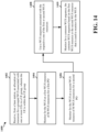
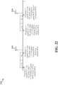
- FIG. 16 is a flowchart of a method 1600 of wireless communication.
- the method may be performed by a base station or a component of a base station (e.g., the base station 102, 108, 310, 704, 804, 904, which may include the memory 376 and which may be the entire base station 310 or a component of the base station 310, such as the TX processor 316, the RX processor 370, and/or the controller/processor 375).
- the illustrated operations of the method 1600 may be omitted, transposed, and/or contemporaneously performed.
- the method may enable a base station to transmit a WUS.
- the base station may group one or more UEs in a UE group.
- the base station may transmit an allocation of resources to one or more UEs in the UE group.
- the allocation of resources may be assigned to the one or more UEs in the UE group.
- the allocation of resources may comprise a group WUS resource within a set of WUS resources associated with a paging occasion.
- the set of WUS resources may include an ungrouped WUS.
- a location of the group WUS may be based on a frequency location of the ungrouped WUS.
- the location of the group WUS resource may be based on the ungrouped WUS having a frequency location in a first resource block and a second resource block of a six resource block bandwidth, e.g., as shown in Pattern 1 of FIG. 4 or Patterns 4 and 6 of FIG. 5 .
- the location of the group WUS resource may be based on the ungrouped WUS having the frequency location in a third resource block and a fourth resource block of the six resource block bandwidth, e.g., as shown in Patterns 2-1 and 2-2 of FIG. 4 or Patterns 8 and 9 of FIG. 5 .
- the location of the group WUS resource may be based on the ungrouped WUS having the frequency location in a fifth resource block and a sixth resource block of the six resource block bandwidth, e.g., as shown in Pattern 3 of FIG. 4 or Patterns 5 and 7 of FIG. 5 .
- the location of the group WUS resource may be based on at least one of the ungrouped WUS having the frequency location in a first resource block and a second resource block of a six resource block bandwidth, the ungrouped WUS having the frequency location in a third resource block and a fourth resource block of the six resource block bandwidth, or the ungrouped WUS having the frequency location in a fifth resource block and a sixth resource block of the six resource block bandwidth.
- the set of WUS resources may not include an ungrouped WUS. In such instances, the location of the group WUS resource may be based on information indicated in a configuration for the group WUS.
- the set of WUS resources may be consecutive in time and frequency. In some aspects, the set of WUS resources may be non-consecutive in time or frequency.
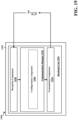
- FIG. 17 is a diagram 1700 illustrating an example of a hardware implementation for an apparatus 1702.
- the apparatus 1702 is a BS and includes a baseband unit 1704.
- the baseband unit 1704 may communicate through a cellular RF transceiver with the UE 104.
- the baseband unit 1704 may include a computer-readable medium / memory.
- the baseband unit 1704 is responsible for general processing, including the execution of software stored on the computer-readable medium / memory.
- the software when executed by the baseband unit 1704, causes the baseband unit 1704 to perform the various functions described supra.
- the computer-readable medium / memory may also be used for storing data that is manipulated by the baseband unit 1704 when executing software.
- the baseband unit 1704 further includes a reception component 1730, a communication manager 1732, and a transmission component 1734.
- the communication manager 1732 includes the one or more illustrated components.
- the components within the communication manager 1732 may be stored in the computer-readable medium / memory and/or configured as hardware within the baseband unit 1704.
- the baseband unit 1704 may be a component of the BS 310 and may include the memory 376 and/or at least one of the TX processor 316, the RX processor 370, and the controller/processor 375.
- the communication manager 1732 includes a grouping component 1740 that is configured to group one or more UEs in a UE group, e.g., as described in connection with block 1602 of the method 1600 of FIG. 16 .
- the transmission component 1534 is configured to transmit to one or more UEs in the UE group, an allocation of resources assigned to the one or more UEs in the UE group, e.g., as described in connection with block 1604 of the method 1600 of FIG. 16 .
- the apparatus may include additional components that perform each of the blocks of the algorithm in the aforementioned flowchart of FIG. 16 .
- each block in the aforementioned flowchart of FIG. 16 may be performed by a component and the apparatus may include one or more of those components.
- the components may be one or more hardware components specifically configured to carry out the stated processes/algorithm, implemented by a processor configured to perform the stated processes/algorithm, stored within a computer-readable medium for implementation by a processor, or some combination thereof.
- the apparatus 1702 includes means for grouping one or more UEs in a UE group; and means for transmitting, to one or more UEs in the UE group, an allocation of resources assigned to the one or more UEs in the UE group, in which the allocation of resources includes a group WUS resource within a set of WUS resources associated with a paging occasion.
- the aforementioned means may be one or more of the aforementioned components of the apparatus 1702 configured to perform the functions recited by the aforementioned means.
- the apparatus 1702 may include the TX Processor 316, the RX Processor 370, and the controller/processor 375.
- the aforementioned means may be the TX Processor 316, the RX Processor 370, and the controller/processor 375 configured to perform the functions recited by the aforementioned means.
- FIG. 18 is a flowchart of a method 1800 of wireless communication.
- the method may be performed by a base station or a component of a base station (e.g., the base station 102, 108, 310, 704, 804, 904, which may include the memory 376 and which may be the entire base station 310 or a component of the base station 310, such as the TX processor 316, the RX processor 370, and/or the controller/processor 375).
- the illustrated operations of the method 1800 may be omitted, transposed, and/or contemporaneously performed.
- the method may enable a base station to transmitting an eDRX configuration to a UE.
- the base station may configure an eDRX configuration.
- the eDRX configuration may include a number of consecutive POs associated with a group WUS.
- the eDRX configuration may include a configured number of consecutive POs associated with an ungrouped WUS.
- the number of consecutive POs associated with the group WUS may be based on the configured number of consecutive POs associated with the ungrouped WUS.
- the eDRX configuration may indicate the number of consecutive POs associated for the group WUS.
- the base station may transmit the eDRX configuration to at least one UE.
- the eDRX configuration may configure the at least one UE for eDRX mode.
- FIG. 19 is a diagram 1900 illustrating an example of a hardware implementation for an apparatus 1902.
- the apparatus 1902 is a BS and includes a baseband unit 1904.
- the baseband unit 1904 may communicate through a cellular RF transceiver with the UE 104.
- the baseband unit 1904 may include a computer-readable medium / memory.
- the baseband unit 1904 is responsible for general processing, including the execution of software stored on the computer-readable medium / memory.
- the software when executed by the baseband unit 1904, causes the baseband unit 1904 to perform the various functions described supra.
- the computer-readable medium / memory may also be used for storing data that is manipulated by the baseband unit 1904 when executing software.
- the baseband unit 1904 further includes a reception component 1930, a communication manager 1932, and a transmission component 1934.
- the communication manager 1932 includes the one or more illustrated components.
- the components within the communication manager 1932 may be stored in the computer-readable medium / memory and/or configured as hardware within the baseband unit 1904.
- the baseband unit 1904 may be a component of the BS 310 and may include the memory 376 and/or at least one of the TX processor 316, the RX processor 370, and the controller/processor 375.
- the communication manager 1932 includes a configuration component 1940 that is configured to configure an eDRX configuration, in which the eDRX configuration includes a number of consecutive POs associated with a group WUS, e.g., as described in connection with block 1802 of the method 1800 of FIG. 18 .
- the transmission component 1534 is configured to transmit the eDRX configuration to at least one UE, e.g., as described in connection with block 1804 of the method 1800 of FIG. 18 .
- the apparatus may include additional components that perform each of the blocks of the algorithm in the aforementioned flowchart of FIG. 17 .
- each block in the aforementioned flowchart of FIG. 17 may be performed by a component and the apparatus may include one or more of those components.
- the components may be one or more hardware components specifically configured to carry out the stated processes/algorithm, implemented by a processor configured to perform the stated processes/algorithm, stored within a computer-readable medium for implementation by a processor, or some combination thereof.
- the apparatus 1902 includes means for configuring an eDRX configuration; and means for transmitting, to at least one UE, the eDRX configuration to configure the at least one UE for eDRX mode.
- the aforementioned means may be one or more of the aforementioned components of the apparatus 1902 configured to perform the functions recited by the aforementioned means.
- the apparatus 1902 may include the TX Processor 316, the RX Processor 370, and the controller/processor 375.
- the aforementioned means may be the TX Processor 316, the RX Processor 370, and the controller/processor 375 configured to perform the functions recited by the aforementioned means.
- FIG. 20 is a flowchart of a method 2000 of wireless communication.
- the method may be performed by a base station or a component of a base station (e.g., the base station 102, 108, 310, 704, 804, 904, which may include the memory 376 and which may be the entire base station 310 or a component of the base station 310, such as the TX processor 316, the RX processor 370, and/or the controller/processor 375).
- one or more of the illustrated operations of the method 2000 may be omitted, transposed, and/or contemporaneously performed.
- the method may enable a base station to transmit a group WUS to one or more UEs in a UE group.
- the base station may configure an allocation of resources for a group WUS associated with one or more UEs in a UE group.
- a first WUS resource of M WUS resources may be associated with a first PO.
- a second WUS resource of M WUS resources may be associated with a second PO.
- a same WUS sequence may be allocated for the UE group to monitor any of the M WUS resources.
- the base station may transmit the group WUS to the one or more UEs in the UE group.
- the base station may transmit the group WUS associated with the one or more UEs at different POs using a pattern associated with a location of the M WUS resources.
- the base station may apply a WUS sequence to the M WUS resources associated with the respective one of the first or second WUS resources.
- the WUS sequence may further include a scrambling sequence associated with the respective one of the first or second WUS resources.
- FIG. 21 is a diagram 2100 illustrating an example of a hardware implementation for an apparatus 2102.
- the apparatus 2102 is a BS and includes a baseband unit 2104.
- the baseband unit 2104 may communicate through a cellular RF transceiver with the UE 104.
- the baseband unit 2104 may include a computer-readable medium / memory.
- the baseband unit 2104 is responsible for general processing, including the execution of software stored on the computer-readable medium / memory.
- the software when executed by the baseband unit 2104, causes the baseband unit 2104 to perform the various functions described supra.
- the computer-readable medium / memory may also be used for storing data that is manipulated by the baseband unit 2104 when executing software.
- the baseband unit 2104 further includes a reception component 2130, a communication manager 2132, and a transmission component 2134.
- the communication manager 2132 includes the one or more illustrated components.
- the components within the communication manager 2132 may be stored in the computer-readable medium / memory and/or configured as hardware within the baseband unit 2104.
- the baseband unit 2104 may be a component of the BS 310 and may include the memory 376 and/or at least one of the TX processor 316, the RX processor 370, and the controller/processor 375.
- the communication manager 2132 includes a configuration component 2140 that is configured to configure an allocation of resources for a group WUS associated with one or more UEs in a UE group, e.g., as described in connection with block 2002 of the method 2000 of FIG. 20 .
- the transmission component 2134 is configured to transmit the group WUS to the one or more UEs in the UE group, e.g., as described in connection with block 2004 of the method 2000 of FIG. 20 .
- the communication manager 2132 further includes an application component 2142 that is configured to apply a WUS sequence to the M WUS resources associated with the respective one of the first or second WUS resources, e.g., as described in connection with block 2006 of the method 2000 of FIG. 20 .
Landscapes
- Engineering & Computer Science (AREA)
- Signal Processing (AREA)
- Computer Networks & Wireless Communication (AREA)
- Mobile Radio Communication Systems (AREA)
Claims (15)
- Verfahren zur drahtlosen Kommunikation, das von einem Benutzergerät, UE, durchgeführt wird, umfassend:Empfangen (1002), von einer Basisstation, einer Ressourcenzuweisung einer Gruppenaufwecksignal-, WUS-, Ressource, die einem oder mehreren UEs in einer UE-Gruppe zugeordnet ist;Bestimmen (1004) eines Orts der Gruppen-WUS-Ressource innerhalb eines Satzes von WUS-Ressourcen, die mit einem Paging-Ereignis assoziiert sind, basierend auf einem Frequenzort einer ungruppierten WUS, die implizit anzeigt, welches einer Vielzahl von WUS-Ressourcenmustern verwendet wird; undÜberwachen (1006) auf eine Gruppen-WUS an dem bestimmten Ort in der Ressourcenzuweisung der Gruppen-WUS-Ressource.
- Verfahren nach Anspruch 1, wobei der Satz von WUS-Ressourcen die ungruppierte WUS beinhaltet, wenn die ungruppierte WUS konfiguriert ist.
- Verfahren nach Anspruch 2, wobei der Ort der Gruppen-WUS-Ressource basierend auf mindestens einem von Folgendem bestimmt wird:der ungruppierten WUS mit dem Frequenzort in einem ersten Ressourcenblock und einem zweiten Ressourcenblock einer Bandbreite von sechs Ressourcenblöcken,der ungruppierten WUS mit dem Frequenzort in einem dritten Ressourcenblock und einem vierten Ressourcenblock der Bandbreite von sechs Ressourcenblöcken, oderder ungruppierten WUS mit dem Frequenzort in einem fünften Ressourcenblock und einem sechsten Ressourcenblock der Bandbreite von sechs Ressourcenblöcken.
- Verfahren nach Anspruch 1, wobei der Satz von WUS-Ressourcen die ungruppierte WUS ausschließt, wenn die ungruppierte WUS nicht konfiguriert ist, und wobei der Ort der Gruppen-WUS-Ressource basierend auf Information bestimmt wird, die in einer Konfiguration angezeigt wird, die mit der Gruppen-WUS assoziiert ist.
- Verfahren nach Anspruch 1, wobei der Satz von WUS-Ressourcen WUS-Ressourcen beinhaltet, die in Zeit und Frequenz aufeinanderfolgend sind.
- Verfahren nach Anspruch 1, wobei der Satz von WUS-Ressourcen WUS-Ressourcen beinhaltet, die in Zeit oder Frequenz nicht aufeinanderfolgend sind.
- Vorrichtung zur drahtlosen Kommunikation an einem Benutzergerät, umfassend:Mittel zum Empfangen (1002), von einer Basisstation, einer Ressourcenzuweisung einer Gruppenaufwecksignal-, WUS-, Ressource, die einem oder mehreren UEs in einer UE-Gruppe zugeordnet ist;Mittel zum Bestimmen (1004) eines Orts der Gruppen-WUS-Ressource innerhalb eines Satzes von WUS-Ressourcen, die mit einem Paging-Ereignis assoziiert sind, basierend auf einem Frequenzort einer ungruppierten WUS, die implizit anzeigt, welches einer Vielzahl von WUS-Ressourcenmustern verwendet wird; undMittel zum Überwachen (1006) auf eine Gruppen-WUS an dem bestimmten Ort in der Ressourcenzuweisung der Gruppen-WUS-Ressource.
- Vorrichtung nach Anspruch 7, wobei der Satz von WUS-Ressourcen die ungruppierte WUS beinhaltet, wenn die ungruppierte WUS konfiguriert ist.
- Vorrichtung nach Anspruch 8, wobei der Ort der Gruppen-WUS-Ressource basierend auf mindestens einem von Folgendem bestimmt wird:der ungruppierten WUS mit dem Frequenzort in einem ersten Ressourcenblock und einem zweiten Ressourcenblock einer Bandbreite von sechs Ressourcenblöcken,der ungruppierten WUS mit dem Frequenzort in einem dritten Ressourcenblock und einem vierten Ressourcenblock der Bandbreite von sechs Ressourcenblöcken, oderder ungruppierten WUS mit dem Frequenzort in einem fünften Ressourcenblock und einem sechsten Ressourcenblock der Bandbreite von sechs Ressourcenblöcken.
- Vorrichtung nach Anspruch 7, wobei der Satz von WUS-Ressourcen die ungruppierte WUS ausschließt, wenn die ungruppierte WUS nicht konfiguriert ist, und wobei der Ort der Gruppen-WUS-Ressource basierend auf Information bestimmt wird, die in einer Konfiguration angezeigt wird, die mit der Gruppen-WUS assoziiert ist.
- Vorrichtung nach Anspruch 7, wobei der Satz von WUS-Ressourcen WUS-Ressourcen beinhaltet, die in Zeit und Frequenz aufeinanderfolgend sind.
- Vorrichtung nach Anspruch 7, wobei der Satz von WUS-Ressourcen WUS-Ressourcen beinhaltet, die in Zeit oder Frequenz nicht aufeinanderfolgend sind.
- Verfahren zur drahtlosen Kommunikation, das von einer Basisstation durchgeführt wird, umfassend:Gruppieren (1602) eines oder mehrerer Benutzergeräte, UEs, in einer UE-Gruppe; undÜbertragen (1604), an ein oder mehrere UEs in der UE-Gruppe, einer Zuweisung von Ressourcen, die dem einen oder den mehreren UEs in der UE-Gruppe zugeordnet sind, wobei die Zuweisung von Ressourcen eine Gruppenaufwecksignal-, WUS-, Ressource innerhalb eines Satzes von WUS-Ressourcen umfasst, die mit einem Paging-Ereignis assoziiert sind, wobei ein Frequenzort einer ungruppierten WUS implizit anzeigt, welches einer Vielzahl von WUS-Ressourcenmustern verwendet wird.
- Vorrichtung zur drahtlosen Kommunikation an einer Basisstation, umfassend:Mittel zum Gruppieren (1602) eines oder mehrerer Benutzergeräte, UEs, in einer UE-Gruppe; undMittel zum Übertragen (1604), an ein oder mehrere UEs in der UE-Gruppe, einer Zuweisung von Ressourcen, die dem einen oder den mehreren UEs in der UE-Gruppe zugeordnet sind, wobei die Zuweisung von Ressourcen eine Gruppenaufwecksignal-, WUS-, Ressource innerhalb eines Satzes von WUS-Ressourcen umfasst, die mit einem Paging-Ereignis assoziiert sind, wobei ein Frequenzort einer ungruppierten WUS implizit anzeigt, welches einer Vielzahl von WUS-Ressourcenmustern verwendet wird.
- Computerprogramm, umfassend Anweisungen, die, wenn das Programm von einem Computer ausgeführt wird, den Computer veranlassen, das Verfahren nach einem der Ansprüche 1-6 oder 13 auszuführen.
Priority Applications (2)
| Application Number | Priority Date | Filing Date | Title |
|---|---|---|---|
| EP23161117.9A EP4216616B1 (de) | 2019-10-04 | 2020-10-01 | Gruppenwecksignal bei verlängertem diskontinuierlichem empfang |
| EP23161120.3A EP4216617B1 (de) | 2019-10-04 | 2020-10-01 | Zuweisung von ressourcen für ein gruppenwecksignal |
Applications Claiming Priority (4)
| Application Number | Priority Date | Filing Date | Title |
|---|---|---|---|
| US201962911163P | 2019-10-04 | 2019-10-04 | |
| US201962931770P | 2019-11-06 | 2019-11-06 | |
| US17/039,123 US11558817B2 (en) | 2019-10-04 | 2020-09-30 | Configuration for ungrouped wake up signal and group wake up signal |
| PCT/US2020/053811 WO2021067602A1 (en) | 2019-10-04 | 2020-10-01 | Configuration for ungrouped wake up signal and group wake up signal |
Related Child Applications (4)
| Application Number | Title | Priority Date | Filing Date |
|---|---|---|---|
| EP23161120.3A Division-Into EP4216617B1 (de) | 2019-10-04 | 2020-10-01 | Zuweisung von ressourcen für ein gruppenwecksignal |
| EP23161120.3A Division EP4216617B1 (de) | 2019-10-04 | 2020-10-01 | Zuweisung von ressourcen für ein gruppenwecksignal |
| EP23161117.9A Division-Into EP4216616B1 (de) | 2019-10-04 | 2020-10-01 | Gruppenwecksignal bei verlängertem diskontinuierlichem empfang |
| EP23161117.9A Division EP4216616B1 (de) | 2019-10-04 | 2020-10-01 | Gruppenwecksignal bei verlängertem diskontinuierlichem empfang |
Publications (3)
| Publication Number | Publication Date |
|---|---|
| EP4038985A1 EP4038985A1 (de) | 2022-08-10 |
| EP4038985B1 true EP4038985B1 (de) | 2025-01-01 |
| EP4038985C0 EP4038985C0 (de) | 2025-01-01 |
Family
ID=75275105
Family Applications (3)
| Application Number | Title | Priority Date | Filing Date |
|---|---|---|---|
| EP23161120.3A Active EP4216617B1 (de) | 2019-10-04 | 2020-10-01 | Zuweisung von ressourcen für ein gruppenwecksignal |
| EP20797271.2A Active EP4038985B1 (de) | 2019-10-04 | 2020-10-01 | Konfiguration für ungruppiertes aufwecksignal und gruppenaufwecksignal |
| EP23161117.9A Active EP4216616B1 (de) | 2019-10-04 | 2020-10-01 | Gruppenwecksignal bei verlängertem diskontinuierlichem empfang |
Family Applications Before (1)
| Application Number | Title | Priority Date | Filing Date |
|---|---|---|---|
| EP23161120.3A Active EP4216617B1 (de) | 2019-10-04 | 2020-10-01 | Zuweisung von ressourcen für ein gruppenwecksignal |
Family Applications After (1)
| Application Number | Title | Priority Date | Filing Date |
|---|---|---|---|
| EP23161117.9A Active EP4216616B1 (de) | 2019-10-04 | 2020-10-01 | Gruppenwecksignal bei verlängertem diskontinuierlichem empfang |
Country Status (7)
| Country | Link |
|---|---|
| US (4) | US11558817B2 (de) |
| EP (3) | EP4216617B1 (de) |
| KR (1) | KR20220079827A (de) |
| CN (3) | CN114557052B (de) |
| BR (1) | BR112022005700A2 (de) |
| TW (1) | TWI873197B (de) |
| WO (1) | WO2021067602A1 (de) |
Families Citing this family (11)
| Publication number | Priority date | Publication date | Assignee | Title |
|---|---|---|---|---|
| US11558817B2 (en) | 2019-10-04 | 2023-01-17 | Qualcomm Incorporated | Configuration for ungrouped wake up signal and group wake up signal |
| EP4059273A4 (de) * | 2019-11-15 | 2023-11-01 | Lenovo (Beijing) Limited | Verfahren und vorrichtung zur wus-erkennung |
| US11576126B2 (en) * | 2020-03-24 | 2023-02-07 | Qualcomm Incorporated | Wakeup signaling identification |
| WO2022151070A1 (zh) * | 2021-01-13 | 2022-07-21 | 华为技术有限公司 | 一种通信方法及装置 |
| JP7362707B2 (ja) * | 2021-10-08 | 2023-10-17 | ソフトバンク株式会社 | 通信及び無線電力伝送を行うシステム、基地局、端末装置、方法及びプログラム |
| US12483985B2 (en) | 2022-04-18 | 2025-11-25 | Samsung Electronics Co., Ltd. | Methods and apparatus for low power wake-up signal waveform design and multiplexing with new radio waveform |
| WO2024102048A1 (en) * | 2022-11-07 | 2024-05-16 | Telefonaktiebolaget Lm Ericsson (Publ) | Ue addressing with wus codes |
| CN119676826A (zh) * | 2023-09-19 | 2025-03-21 | 夏普株式会社 | 由用户设备执行的方法以及用户设备 |
| WO2025171538A1 (en) * | 2024-02-15 | 2025-08-21 | Qualcomm Incorporated | Low power wake up signal design |
| WO2025174146A1 (ko) * | 2024-02-16 | 2025-08-21 | 엘지전자 주식회사 | 무선 통신 시스템에서 신호를 송수신하는 방법 및 장치 |
| WO2025123731A1 (en) * | 2024-08-09 | 2025-06-19 | Lenovo (Beijing) Limited | Wus resource determinaton |
Family Cites Families (26)
| Publication number | Priority date | Publication date | Assignee | Title |
|---|---|---|---|---|
| US10004099B2 (en) * | 2015-05-15 | 2018-06-19 | Mediatek Inc. | Efficient discontinuous reception in a mobile network |
| DE112015006954T5 (de) | 2015-09-25 | 2018-06-21 | Intel Corporation | Energiespar-aufweckfunk für mobilgeräte |
| CN107979866A (zh) * | 2016-10-25 | 2018-05-01 | 华为技术有限公司 | 唤醒方法和设备 |
| US11284372B2 (en) | 2017-03-24 | 2022-03-22 | Apple Inc. | Wake up signal for machine type communication and narrowband-internet-of-things devices |
| US20180368115A1 (en) * | 2017-06-16 | 2018-12-20 | Mediatek Inc. | Design of group-common pdcch |
| CN111770561B (zh) * | 2017-08-28 | 2024-12-13 | 息思维国际股份有限公司 | 一种被用于节省功率的用户、基站中的方法和装置 |
| US10880834B2 (en) * | 2017-09-15 | 2020-12-29 | Qualcomm Incorporated | Techniques and apparatuses for wakeup signal design and resource allocation |
| CN109586840A (zh) * | 2017-09-28 | 2019-04-05 | 珠海市魅族科技有限公司 | 一种发送或接收唤醒信号的方法和装置 |
| US11032047B2 (en) * | 2017-09-29 | 2021-06-08 | Qualcomm Incorporated | Techniques and apparatuses for wakeup signal design and resource allocation |
| WO2019086674A1 (en) * | 2017-11-03 | 2019-05-09 | Sony Mobile Communications Inc. | Combined wake-up signal for multiple paging occasions |
| CN111279766B (zh) * | 2017-11-15 | 2023-04-07 | 索尼公司 | 降低所有类型的终端装置的功耗 |
| US11290957B2 (en) | 2017-11-17 | 2022-03-29 | Samsung Electronics Co., Ltd. | Sequence design of wake-up signals and resynchronization sequence |
| US11546851B2 (en) * | 2018-01-26 | 2023-01-03 | Lg Electronics Inc. | Method for transmitting/receiving signal in wireless communication system and device therefor |
| US11368910B2 (en) * | 2018-01-26 | 2022-06-21 | Lg Electronics Inc. | Method and device for transmitting/receiving wireless signal in wireless communication system |
| US11297674B2 (en) * | 2018-02-14 | 2022-04-05 | Samsung Electronics Co., Ltd. | Method and apparatus for power savings at a user equipment |
| CN111727582B (zh) * | 2018-02-15 | 2024-09-20 | 索尼公司 | 操作基础设施设备的方法、基础设施设备和通信装置 |
| US10484228B2 (en) * | 2018-03-05 | 2019-11-19 | Qualcomm Incorporated | Wakeup radio transmit diversity |
| US11284477B2 (en) | 2018-07-24 | 2022-03-22 | Apple Inc. | Downlink control channel signaling for improving UE power consumption |
| DE112019003998T5 (de) | 2018-08-09 | 2021-04-22 | Lg Electronics Inc. | Verfahren und vorrichtung für eine kommunikationsvorrichtung zum erfassen oder übertragen eines wus-signals in einem drahtloskommunikationssystem |
| CN110536379B (zh) | 2018-08-10 | 2025-07-01 | 中兴通讯股份有限公司 | 唤醒信号发送方法、检测方法、相关装置及存储介质 |
| WO2020067718A1 (en) * | 2018-09-27 | 2020-04-02 | Samsung Electronics Co., Ltd. | Method, user equipment, base station, and readable storage medium for transmitting wake-up signal |
| CN113196843B (zh) | 2018-11-01 | 2024-11-19 | 索尼公司 | 增强寻呼操作的方法、相关无线装置以及相关网络节点 |
| US11510146B2 (en) * | 2019-02-25 | 2022-11-22 | Qualcomm Incorporated | Methods and apparatus for a group wake up signal |
| JP7512258B2 (ja) * | 2019-04-11 | 2024-07-08 | 株式会社Nttドコモ | 基地局、端末、通信システム、及び通信方法 |
| CN112399527B (zh) * | 2019-08-13 | 2025-01-14 | 苹果公司 | 扩展的非连续接收模式中的通知支持 |
| US11558817B2 (en) | 2019-10-04 | 2023-01-17 | Qualcomm Incorporated | Configuration for ungrouped wake up signal and group wake up signal |
-
2020
- 2020-09-30 US US17/039,123 patent/US11558817B2/en active Active
- 2020-10-01 EP EP23161120.3A patent/EP4216617B1/de active Active
- 2020-10-01 KR KR1020227010351A patent/KR20220079827A/ko active Pending
- 2020-10-01 BR BR112022005700A patent/BR112022005700A2/pt unknown
- 2020-10-01 CN CN202080068089.9A patent/CN114557052B/zh active Active
- 2020-10-01 EP EP20797271.2A patent/EP4038985B1/de active Active
- 2020-10-01 EP EP23161117.9A patent/EP4216616B1/de active Active
- 2020-10-01 CN CN202410312027.8A patent/CN118233994A/zh active Pending
- 2020-10-01 WO PCT/US2020/053811 patent/WO2021067602A1/en not_active Ceased
- 2020-10-01 CN CN202410312029.7A patent/CN118233995A/zh active Pending
- 2020-10-05 TW TW109134432A patent/TWI873197B/zh active
-
2021
- 2021-12-30 US US17/646,639 patent/US11910319B2/en active Active
- 2021-12-30 US US17/646,629 patent/US11956724B2/en active Active
-
2024
- 2024-01-03 US US18/403,625 patent/US12335871B2/en active Active
Also Published As
| Publication number | Publication date |
|---|---|
| WO2021067602A1 (en) | 2021-04-08 |
| US11558817B2 (en) | 2023-01-17 |
| US11956724B2 (en) | 2024-04-09 |
| US20240179629A1 (en) | 2024-05-30 |
| TWI873197B (zh) | 2025-02-21 |
| BR112022005700A2 (pt) | 2022-06-21 |
| CN118233994A (zh) | 2024-06-21 |
| CN114557052A (zh) | 2022-05-27 |
| US20220124621A1 (en) | 2022-04-21 |
| US20220124620A1 (en) | 2022-04-21 |
| EP4216617B1 (de) | 2025-11-19 |
| EP4216617C0 (de) | 2025-11-19 |
| EP4216617A1 (de) | 2023-07-26 |
| EP4216616A1 (de) | 2023-07-26 |
| EP4216616B1 (de) | 2025-11-19 |
| US12335871B2 (en) | 2025-06-17 |
| CN114557052B (zh) | 2024-03-15 |
| CN118233995A (zh) | 2024-06-21 |
| EP4216616C0 (de) | 2025-11-19 |
| US11910319B2 (en) | 2024-02-20 |
| EP4038985A1 (de) | 2022-08-10 |
| KR20220079827A (ko) | 2022-06-14 |
| US20210105718A1 (en) | 2021-04-08 |
| TW202119846A (zh) | 2021-05-16 |
| EP4038985C0 (de) | 2025-01-01 |
Similar Documents
| Publication | Publication Date | Title |
|---|---|---|
| EP4038985B1 (de) | Konfiguration für ungruppiertes aufwecksignal und gruppenaufwecksignal | |
| US11115110B2 (en) | Default beam selection based on a subset of coresets | |
| EP4038809B1 (de) | Demodulationsreferenzsignal mit reduziertem overhead | |
| WO2021067890A1 (en) | Phase tracking reference signal for multi-transmit/receive points | |
| US10827440B2 (en) | Indication of potential NR UL transmission in NE-DC | |
| US12425937B2 (en) | UE requested SMTC window configuration adaptation | |
| EP4197276A1 (de) | Gemeinsame nutzung der kanalbelegungszeit (cot) unter heterogenen bandbreitenbedingungen | |
| WO2021143380A1 (en) | Methods and apparatus for updating pucch spatial relation information | |
| US11323980B2 (en) | System and method for scheduling narrowband reference signals in paging occasions | |
| WO2023151017A1 (en) | Simultaneous transmission of supplementary uplink carriers | |
| WO2019148433A1 (en) | Enhanced four port narrowband reference signal (nrs) | |
| US11224060B2 (en) | Gap transmission in channel occupancy time |
Legal Events
| Date | Code | Title | Description |
|---|---|---|---|
| STAA | Information on the status of an ep patent application or granted ep patent |
Free format text: STATUS: UNKNOWN |
|
| STAA | Information on the status of an ep patent application or granted ep patent |
Free format text: STATUS: THE INTERNATIONAL PUBLICATION HAS BEEN MADE |
|
| PUAI | Public reference made under article 153(3) epc to a published international application that has entered the european phase |
Free format text: ORIGINAL CODE: 0009012 |
|
| STAA | Information on the status of an ep patent application or granted ep patent |
Free format text: STATUS: REQUEST FOR EXAMINATION WAS MADE |
|
| 17P | Request for examination filed |
Effective date: 20220309 |
|
| AK | Designated contracting states |
Kind code of ref document: A1 Designated state(s): AL AT BE BG CH CY CZ DE DK EE ES FI FR GB GR HR HU IE IS IT LI LT LU LV MC MK MT NL NO PL PT RO RS SE SI SK SM TR |
|
| DAV | Request for validation of the european patent (deleted) | ||
| DAX | Request for extension of the european patent (deleted) | ||
| GRAP | Despatch of communication of intention to grant a patent |
Free format text: ORIGINAL CODE: EPIDOSNIGR1 |
|
| STAA | Information on the status of an ep patent application or granted ep patent |
Free format text: STATUS: GRANT OF PATENT IS INTENDED |
|
| RIC1 | Information provided on ipc code assigned before grant |
Ipc: H04W 72/0453 20230101ALN20240306BHEP Ipc: H04W 72/0446 20230101ALN20240306BHEP Ipc: H04L 5/00 20060101ALI20240306BHEP Ipc: H04W 76/28 20180101ALI20240306BHEP Ipc: H04W 68/02 20090101ALI20240306BHEP Ipc: H04W 52/02 20090101AFI20240306BHEP |
|
| INTG | Intention to grant announced |
Effective date: 20240321 |
|
| GRAJ | Information related to disapproval of communication of intention to grant by the applicant or resumption of examination proceedings by the epo deleted |
Free format text: ORIGINAL CODE: EPIDOSDIGR1 |
|
| STAA | Information on the status of an ep patent application or granted ep patent |
Free format text: STATUS: REQUEST FOR EXAMINATION WAS MADE |
|
| INTC | Intention to grant announced (deleted) | ||
| GRAP | Despatch of communication of intention to grant a patent |
Free format text: ORIGINAL CODE: EPIDOSNIGR1 |
|
| STAA | Information on the status of an ep patent application or granted ep patent |
Free format text: STATUS: GRANT OF PATENT IS INTENDED |
|
| RIC1 | Information provided on ipc code assigned before grant |
Ipc: H04W 72/0453 20230101ALN20240805BHEP Ipc: H04W 72/0446 20230101ALN20240805BHEP Ipc: H04L 5/00 20060101ALI20240805BHEP Ipc: H04W 76/28 20180101ALI20240805BHEP Ipc: H04W 68/02 20090101ALI20240805BHEP Ipc: H04W 52/02 20090101AFI20240805BHEP |
|
| INTG | Intention to grant announced |
Effective date: 20240816 |
|
| GRAS | Grant fee paid |
Free format text: ORIGINAL CODE: EPIDOSNIGR3 |
|
| GRAA | (expected) grant |
Free format text: ORIGINAL CODE: 0009210 |
|
| STAA | Information on the status of an ep patent application or granted ep patent |
Free format text: STATUS: THE PATENT HAS BEEN GRANTED |
|
| AK | Designated contracting states |
Kind code of ref document: B1 Designated state(s): AL AT BE BG CH CY CZ DE DK EE ES FI FR GB GR HR HU IE IS IT LI LT LU LV MC MK MT NL NO PL PT RO RS SE SI SK SM TR |
|
| REG | Reference to a national code |
Ref country code: GB Ref legal event code: FG4D |
|
| REG | Reference to a national code |
Ref country code: CH Ref legal event code: EP |
|
| REG | Reference to a national code |
Ref country code: DE Ref legal event code: R096 Ref document number: 602020044122 Country of ref document: DE |
|
| REG | Reference to a national code |
Ref country code: IE Ref legal event code: FG4D |
|
| U01 | Request for unitary effect filed |
Effective date: 20250116 |
|
| U07 | Unitary effect registered |
Designated state(s): AT BE BG DE DK EE FI FR IT LT LU LV MT NL PT RO SE SI Effective date: 20250122 |
|
| PG25 | Lapsed in a contracting state [announced via postgrant information from national office to epo] |
Ref country code: PL Free format text: LAPSE BECAUSE OF FAILURE TO SUBMIT A TRANSLATION OF THE DESCRIPTION OR TO PAY THE FEE WITHIN THE PRESCRIBED TIME-LIMIT Effective date: 20250101 |
|
| PG25 | Lapsed in a contracting state [announced via postgrant information from national office to epo] |
Ref country code: ES Free format text: LAPSE BECAUSE OF FAILURE TO SUBMIT A TRANSLATION OF THE DESCRIPTION OR TO PAY THE FEE WITHIN THE PRESCRIBED TIME-LIMIT Effective date: 20250101 |
|
| PG25 | Lapsed in a contracting state [announced via postgrant information from national office to epo] |
Ref country code: NO Free format text: LAPSE BECAUSE OF FAILURE TO SUBMIT A TRANSLATION OF THE DESCRIPTION OR TO PAY THE FEE WITHIN THE PRESCRIBED TIME-LIMIT Effective date: 20250401 Ref country code: IS Free format text: LAPSE BECAUSE OF FAILURE TO SUBMIT A TRANSLATION OF THE DESCRIPTION OR TO PAY THE FEE WITHIN THE PRESCRIBED TIME-LIMIT Effective date: 20250501 |
|
| PG25 | Lapsed in a contracting state [announced via postgrant information from national office to epo] |
Ref country code: HR Free format text: LAPSE BECAUSE OF FAILURE TO SUBMIT A TRANSLATION OF THE DESCRIPTION OR TO PAY THE FEE WITHIN THE PRESCRIBED TIME-LIMIT Effective date: 20250101 |
|
| PG25 | Lapsed in a contracting state [announced via postgrant information from national office to epo] |
Ref country code: GR Free format text: LAPSE BECAUSE OF FAILURE TO SUBMIT A TRANSLATION OF THE DESCRIPTION OR TO PAY THE FEE WITHIN THE PRESCRIBED TIME-LIMIT Effective date: 20250402 |
|
| PG25 | Lapsed in a contracting state [announced via postgrant information from national office to epo] |
Ref country code: CZ Free format text: LAPSE BECAUSE OF FAILURE TO SUBMIT A TRANSLATION OF THE DESCRIPTION OR TO PAY THE FEE WITHIN THE PRESCRIBED TIME-LIMIT Effective date: 20250101 |
|
| PG25 | Lapsed in a contracting state [announced via postgrant information from national office to epo] |
Ref country code: SM Free format text: LAPSE BECAUSE OF FAILURE TO SUBMIT A TRANSLATION OF THE DESCRIPTION OR TO PAY THE FEE WITHIN THE PRESCRIBED TIME-LIMIT Effective date: 20250101 |
|
| PGFP | Annual fee paid to national office [announced via postgrant information from national office to epo] |
Ref country code: GB Payment date: 20250911 Year of fee payment: 6 |
|
| PGFP | Annual fee paid to national office [announced via postgrant information from national office to epo] |
Ref country code: IE Payment date: 20250912 Year of fee payment: 6 |
|
| U20 | Renewal fee for the european patent with unitary effect paid |
Year of fee payment: 6 Effective date: 20250915 |
|
| PG25 | Lapsed in a contracting state [announced via postgrant information from national office to epo] |
Ref country code: SK Free format text: LAPSE BECAUSE OF FAILURE TO SUBMIT A TRANSLATION OF THE DESCRIPTION OR TO PAY THE FEE WITHIN THE PRESCRIBED TIME-LIMIT Effective date: 20250101 |
|
| PLBE | No opposition filed within time limit |
Free format text: ORIGINAL CODE: 0009261 |
|
| STAA | Information on the status of an ep patent application or granted ep patent |
Free format text: STATUS: NO OPPOSITION FILED WITHIN TIME LIMIT |
|
| 26N | No opposition filed |
Effective date: 20251002 |