EP4038720B1 - System, master-testvorrichtung und verfahren zum testen von drahtlosen leistungsübertragungsvorrichtungen mit mehreren drahtlosen leistungssendern - Google Patents
System, master-testvorrichtung und verfahren zum testen von drahtlosen leistungsübertragungsvorrichtungen mit mehreren drahtlosen leistungssendern Download PDFInfo
- Publication number
- EP4038720B1 EP4038720B1 EP21836533.6A EP21836533A EP4038720B1 EP 4038720 B1 EP4038720 B1 EP 4038720B1 EP 21836533 A EP21836533 A EP 21836533A EP 4038720 B1 EP4038720 B1 EP 4038720B1
- Authority
- EP
- European Patent Office
- Prior art keywords
- wireless power
- test
- slave
- master
- devices
- Prior art date
- Legal status (The legal status is an assumption and is not a legal conclusion. Google has not performed a legal analysis and makes no representation as to the accuracy of the status listed.)
- Active
Links
Images


Classifications
-
- H—ELECTRICITY
- H02—GENERATION; CONVERSION OR DISTRIBUTION OF ELECTRIC POWER
- H02J—CIRCUIT ARRANGEMENTS OR SYSTEMS FOR SUPPLYING OR DISTRIBUTING ELECTRIC POWER; SYSTEMS FOR STORING ELECTRIC ENERGY
- H02J50/00—Circuit arrangements or systems for wireless supply or distribution of electric power
- H02J50/10—Circuit arrangements or systems for wireless supply or distribution of electric power using inductive coupling
- H02J50/12—Circuit arrangements or systems for wireless supply or distribution of electric power using inductive coupling of the resonant type
-
- G—PHYSICS
- G01—MEASURING; TESTING
- G01R—MEASURING ELECTRIC VARIABLES; MEASURING MAGNETIC VARIABLES
- G01R31/00—Arrangements for testing electric properties; Arrangements for locating electric faults; Arrangements for electrical testing characterised by what is being tested not provided for elsewhere
- G01R31/40—Testing power supplies
-
- H—ELECTRICITY
- H02—GENERATION; CONVERSION OR DISTRIBUTION OF ELECTRIC POWER
- H02J—CIRCUIT ARRANGEMENTS OR SYSTEMS FOR SUPPLYING OR DISTRIBUTING ELECTRIC POWER; SYSTEMS FOR STORING ELECTRIC ENERGY
- H02J50/00—Circuit arrangements or systems for wireless supply or distribution of electric power
- H02J50/40—Circuit arrangements or systems for wireless supply or distribution of electric power using two or more transmitting or receiving devices
-
- H—ELECTRICITY
- H02—GENERATION; CONVERSION OR DISTRIBUTION OF ELECTRIC POWER
- H02J—CIRCUIT ARRANGEMENTS OR SYSTEMS FOR SUPPLYING OR DISTRIBUTING ELECTRIC POWER; SYSTEMS FOR STORING ELECTRIC ENERGY
- H02J50/00—Circuit arrangements or systems for wireless supply or distribution of electric power
- H02J50/60—Circuit arrangements or systems for wireless supply or distribution of electric power responsive to the presence of foreign objects, e.g. detection of living beings
-
- H—ELECTRICITY
- H04—ELECTRIC COMMUNICATION TECHNIQUE
- H04B—TRANSMISSION
- H04B17/00—Monitoring; Testing
- H04B17/10—Monitoring; Testing of transmitters
- H04B17/15—Performance testing
- H04B17/17—Detection of non-compliance or faulty performance, e.g. response deviations
-
- H—ELECTRICITY
- H04—ELECTRIC COMMUNICATION TECHNIQUE
- H04B—TRANSMISSION
- H04B17/00—Monitoring; Testing
- H04B17/20—Monitoring; Testing of receivers
- H04B17/24—Monitoring; Testing of receivers with feedback of measurements to the transmitter
-
- H—ELECTRICITY
- H04—ELECTRIC COMMUNICATION TECHNIQUE
- H04B—TRANSMISSION
- H04B5/00—Near-field transmission systems, e.g. inductive or capacitive transmission systems
- H04B5/70—Near-field transmission systems, e.g. inductive or capacitive transmission systems specially adapted for specific purposes
- H04B5/79—Near-field transmission systems, e.g. inductive or capacitive transmission systems specially adapted for specific purposes for data transfer in combination with power transfer
Definitions
- the present invention generally relates to the field of wireless power transfer, and more specifically to testing of wireless power transfer equipment. Even more specifically, the present invention relates to a system and a method for testing of wireless power transfer equipment that has a plurality of wireless power transmitters adapted to operate concurrently for wireless power transfer. The present invention also relates to a master test device.
- Wireless power transfer is growing increasingly popular, for instance for wireless battery charging of mobile devices like mobile terminals, tablet computers, laptop computers, cameras, audio players, electric toothbrushes, wireless headsets and smart watches, as well as various other consumer products and appliances.
- the Wireless Power Consortium has developed a wireless power transfer standard known as Qi.
- Other known wireless power transfer approaches include Alliance for Wireless Power, and Power Matters Alliance.
- the wireless power transfer standard known as Qi by the Wireless Power Consortium will be referred to, without limitation, throughout this document as the presently preferred wireless power transfer manner applicable to the present invention.
- the invention may generally be applied also to other wireless power transfer standards or approaches, including but not limited to the ones mentioned above.
- a base station contains a subsystem (a power transmitter) that comprises a primary coil
- a mobile device contains a subsystem (a power receiver) that comprises a secondary coil.
- the primary coil and the secondary coil will constitute the two halves of a coreless resonant transformer.
- a base station has a flat surface, on top of which a user can place one or more mobile devices so as to enjoy wireless battery charging or operational power supply for the mobile device(s) placed on the base station.
- Fig. 1 illustrates a wireless power transmitter device 20' for wireless power transfer to a mobile device 10 (i.e., a wireless power receiver device).
- the mobile device 10 may, for instance, be a mobile terminal (e.g. smart phone) 10a, tablet computer 10b (e.g. surf pad), laptop computer 10c, smart watch 10d, camera, audio player, rechargeable toothbrush, wireless headset, or another kind of consumer product or appliance.
- the wireless power transfer will be described as being compliant with the Qi standard by the Wireless Power Consortium, without limitation; hence, the wireless power transmitter device 20 is a base station in the Qi terminology.
- the invention is - as mentioned above - generally applicable also to other wireless power transfer standards or approaches.
- the wireless power transmitter device 20' comprises a wireless power transmitter 22 having a wireless power transmitter coil 24 and being controlled by a controller 26.
- the mobile device 10 comprises a wireless power receiver 12 having a wireless power receiver coil 14.
- the wireless power transmitter device 20' will transfer power wirelessly to the mobile device 10 by way of magnetic induction 18 via the wireless power transmitter coil 24 and wireless power receiver coil 14.
- the power received by the wireless power receiver coil 14 will drive a load 16 in the mobile device 10.
- the load 16 may be a rechargeable battery, such as a lithium ion battery; hence, the wireless power transmitter device 20' will act as a wireless power charger for the mobile device 10.
- the load 16 may be electronic circuitry in the mobile device, wherein the wireless power transmitter device 20' will act as a wireless power supply for the mobile device 10.
- wireless charging will be used as an example of wireless power transfer, i.e. a species among a genus, without limitation.
- interest groups may for instance involve any of the following: developers, manufacturers or suppliers of mobile devices; developers, manufacturers or suppliers of wireless power transmitter devices; test or compliance entities in the field of wireless power transfer; and test or compliance entities in the field of consumer product safety.
- Fig. 1 Conventional wireless power charging equipment as illustrated by Fig. 1 performs a 1-to-1 function in the sense that one (1) wireless power transmitter device provides power (energy) to one (1) wireless power receiver device. With the growth of adoption of wireless power transfer into the market, more and more devices become available which will require wireless charging. Accordingly, wireless power charging equipment has begun to appear with which a single wireless power transmitter device can provide power to multiple wireless power receiver devices.
- Fig. 2 is a schematic block diagram of a 1-to-many wireless power transmitter device 20 for wireless power transfer to a plurality of mobile devices 10a, 10a', 10d.
- the wireless power transmitter device 20 comprises a plurality of wireless power transmitters 22a-n, each being adapted for wireless power transfer, as seen at 18a-18n.
- the wireless power transmitters 22a-n have respective wireless power transmitter coils 24a-n and are controlled by a common controller 26. Accordingly, the plurality of wireless power transmitters 22a-n are adapted to be operated concurrently for wireless power transfer to respective wireless power receiver devices, i.e. respective ones of the mobile devices 10a, 10a', 10d.
- the compliance testing program for the WPC only performs testing functionality for wireless power transmitter devices in a 1-to-1 capacity. This means that the compliance testing only verifies the performance and compliance of the equipment while providing power to a single test device acting as a wireless power receiver.
- the present inventor has realized that a wireless power transmitter device that supports 1-to-many charging can suffer from performance degradation when it is providing power to several devices at the same time. It is essential that wireless charging equipment carrying the Qi logo (as controlled by the WPC) is compliant under all possible operating conditions.
- One example of such influence can be interference on the communication channel experienced by the wireless power transmitter device or a first wireless power receiver device due to cross-talk or noise generated by a second wireless power receiver device.
- Another example can be the heating up of one part of the wireless power transmitter device or of a first wireless power receiver device, that may influence the behavior of a second wireless power receiver device.
- these problems may occur for instance because of a limited distance between adjacent wireless power transmitters 22a-n or between wireless power receiver devices 10, 10'a, 10d.
- the wireless power transmitter device may not be capable to provide the required power when multiple wireless power receiver device are being charged; not just average powers, but also regarding temporary transients where power demands can spike for a brief moment.
- EP3542475A1 discloses, in the wording of the claims, a system, a method and a master test device for testing of wireless power transfer equipment comprising a wireless power transmitter adapted for wireless power transfer to a wireless power receiver device, the system comprising:
- a first inventive aspect is a system for testing of wireless power transfer equipment that has a plurality of wireless power transmitters adapted for concurrent wireless power transfer to respective wireless power receiver devices.
- the system comprises a master test device with a local data communication interface, a master controller, and an output unit.
- the system further comprises a number of slave test devices.
- Each slave test device has a local data communication interface being adapted for data communication with the master test device, a wireless power receiver, and a local controller configured for performing a wireless power transfer test procedure upon any of the wireless power transmitters of the wireless power transfer equipment under test.
- the master test device is configured to communicate via its local data communication interface with the slave test devices.
- the master controller of the master test device is configured to command the slave test devices to perform their respective test procedures upon respective ones of the wireless power transmitters of the wireless power transfer equipment while being in concurrent operation under test, receive result data from the respective test procedures performed by the slave test devices, and provide an output by the output unit of the master test device. The output is based on the respective result data obtained from the slave test devices.
- a second inventive aspect is a method for testing of wireless power transfer equipment of a type that has a plurality of wireless power transmitters adapted for concurrent wireless power transfer to respective wireless power receiver devices. The method involves:
- a third inventive aspect is a master test device for testing of wireless power transfer equipment that has a plurality of wireless power transmitters adapted for concurrent wireless power transfer to respective wireless power receiver devices.
- the master test device comprises a local data communication interface, a master controller, and an output unit.
- the master test device is configured to communicate with a plurality of slave test devices via the local data communication interface.
- the master controller of the master test device is configured to command the slave test devices to perform respective wireless power transfer test procedures upon respective ones of the wireless power transmitters of the wireless power transfer equipment while being in concurrent operation under test, receive result data from the respective test procedures performed by the slave test devices, and provide an output by the output unit of the master test device. The output is based on the respective result data obtained from the slave test devices.
- a fourth aspect which is not claimed is a slave test device for testing of wireless power transfer equipment that has a plurality of wireless power transmitters adapted for concurrent wireless power transfer to respective wireless power receiver devices.
- the slave test device comprises a local data communication interface being adapted for data communication with a master test device, a wireless power receiver, and a local controller configured for performing a wireless power transfer test procedure pertaining to any of the wireless power transmitters of the wireless power transfer equipment under test.
- the slave test device is configured to communicate via its local data communication interface with the master test device.
- the local controller of the slave test device is configured to receive a command from the master test device, perform the wireless power transfer test procedure upon one of the wireless power transmitters, generate result data from the performance of the wireless power transfer test procedure, and transmit the result data to the master test device.
- the number of slave test devices used in this invention may be an arbitrary number of slave test devices, including a case where only a single slave test device is used.
- at least two slave test devices are used, wherein in such a case the locution "a number of slave test devices" will mean "a plurality of slave test devices". If only a single slave test device is used, it will perform its wireless power transfer test procedure on one of the wireless power transmitters of the wireless power transfer equipment under test. If a plurality of slave test devices are used, the slave test devices will perform their respective wireless power transfer test procedures on respective ones of the wireless power transmitters of the wireless power transfer equipment under test.
- the output is based on the respective result data obtained from the slave test devices does not in any way preclude that the output is also affected or derived from other information, including test result data obtained by the master test device itself.
- Some of the disclosed embodiments have a main probe device for use directly by the master test device to this end.
- an inventive insight by the present inventor is the benefit that comes from being able to monitor and control both advanced compliance test equipment (the master test device) and one or more additional devices (the slave test devices) when performing compliance tests on wireless power transfer equipment having a plurality of wireless power transmitters. This is especially so when time-critical events are being monitored and correlation between events on the separate wireless power transmitters needs to be proven. This is where the invention comes in.
- the invention comprises an overall testing system that makes use of both an advanced compliance test tool (the master test device) as well as a number of less advanced slave test devices that can connect to the advanced compliance test tool.
- the master test device is a centralized intelligence in the system that controls (or sends information for the purpose of control) to all connected equipment based on observations (or received information on observations) on all equipment.
- the slave test devices are capable of communicating with the master test device and act upon instructions from that device while reporting back measurement results.
- Such a configuration can turn any standalone auxiliary test device into an add-on to the complete multi-device test setup, all is needed is a communication interface (like an API) that allows it to act as a slave test device by communicating with the master test device acting as a host in the test setup.
- the master test device can monitor with extremely high accuracy the quality of the communication channel by using, for instance, error rates or bit error rates. Then, while it is monitoring this parameter on one charging interface, it can manipulate the level of interference by adjusting the communication parameters of the slave test device(s).
- the test system can look for specific worst-case use by, for instance, perturb-and-observe algorithms to find any possible problem areas. Such a solution would help product manufacturers find weaknesses in their product and make improvements and it would help standardization organizations by better test equipment, automated to find worst-case conditions improving both testing efficiency as well as effectivity.
- the scope of parameters that can be measured, observed, and influenced is not restricted to communication, but covers all fields from power electronics and electromagnetics to user experience and safety. This includes power measurements, magnetic field strengths, but also temperatures of the device itself or of any foreign objects as used to evaluate the safety performance of wireless power products.
- One goal of the system may even be to provide a fully autonomous solution that can search for problem areas in different performance aspects of wireless charging systems.
- the system can observe and compare dynamic patterns (studying transient responses) in addition to static operating conditions.
- Fig. 3 illustrates the overall composition of a system 1 for testing of wireless power transfer equipment 20 that has a plurality of wireless power transmitters adapted for wireless power transfer, i.e. 1-to-many wireless power transfer equipment.
- the system 1 may, for instance, be used for testing of a 1-to-many wireless power transmitter device 20 like the one shown in Fig. 2 , having a plurality of wireless power transmitters 22a-n adapted for concurrent (parallel) wireless power transfer to respective wireless power receiver devices such as, for instance, mobile devices 10a, 10a', 10d in Fig. 2 .
- the wireless power receiver devices of, for instance, Fig. 2 are not part of the system 1 for testing.
- the system 1 will test the wireless power transfer equipment 20 with its plurality of wireless power transmitters with respect to its ability to provide wireless power, which in normal (non-test) operation would mean providing wireless power to such wireless power receiver devices concurrently. Accordingly, the testing may, for instance seek to assess or verify the ability of the wireless power transmitter device 20 with its plurality of wireless power transmitters 22a-n to comply with a wireless power transfer standard, such as Qi by the WPC.
- a wireless power transfer standard such as Qi by the WPC.
- the system 1 may be used for similar testing of a plurality of stand-alone 1-1 wireless power transmitter devices, each having a respective wireless power transmitter 22a-n, for instance when the stand-alone 1-to-1 wireless power transmitter devices operate in close proximity of each other (a.k.a. co-existence testing).
- a further use of the system 1 is to test a plurality of 1-to-n wireless power transmitter devices that operate jointly together, such as five 1-to-2 wireless power transmitter devices, or two 1-to-5 wireless power transmitter devices.
- the system 1 has two types of principal components in a hierarchical configuration: a master test device 40, and a number of slave test devices 30a-n.
- the slave test devices 30a-n are controlled by the master test device 40 to perform respective tests upon respective ones of the wireless power transmitters of the wireless power transfer equipment 20 while being in concurrent (parallel) operation under test, and to report test result data back to the master test device 40.
- the master test device 40 may use the reported test result data from the slave test devices 30a-n when concluding on overall and/or detailed test results.
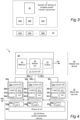
- Fig. 4 is a detailed block diagram of a first embodiment of the system 1 for testing of wireless power transfer equipment in the form of a 1-to-many wireless power transmitter device 20 having a plurality of wireless power transmitters 22a-n adapted for wireless power transfer.
- the system 1 comprises a master test device 40 and a number of slave test devices 30a-n.
- the wireless power transmitter device 20 may, for instance, be like the one previously described for Fig. 2 .
- Each slave test device 30a-n has a local data communication interface 38a-n being adapted for data communication with the master test device 40.
- the master test device 40 is configured to communicate via its local data communication interface 41 with the slave test devices 30a-n, and the slave test devices 30a-n will use their respective local data communication interfaces 38a-n for this communication.
- Each slave test device 30a-n also has a wireless power receiver 32a-n with a wireless power receiver coil 34a-n, a local controller 37a-n and a suitable load 36a-n.
- the load 36a-n may be provided to handle excess power received by the wireless power receiver coil 34a-n. For instance, a suitably dimensioned resistor may be used.
- the load 36a-n may be controllable in some embodiments.
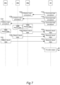
- Fig. 7 being a schematic flowchart diagram that illustrates the operation of the system 1 for testing of the 1-to-many wireless power transmitter device 20.
- the local controller 37a-n of each slave test device 30a-n is configured for performing a wireless power transfer test procedure 120a-n upon any of the wireless power transmitters 22a-n of the wireless power transmitter device 20 under test.
- the slave test device 30a-n are configured for performing respective wireless power transfer test procedures 120a-n upon respective ones of the wireless power transmitters 22a-n of the wireless power transmitter device 20 under test. This may involve the first slave test device 30a performing a wireless power transfer test procedure 120a upon the first wireless power transmitter 22a, the second slave test device 30b performing a wireless power transfer test procedure 120b upon the second wireless power transmitter 22b, and so on.
- the master controller 42 of the master test device 40 is configured by way of communication 46a-n to command 110a-n the slave test devices 30a-n to perform their respective test procedures 120a-n upon the respective wireless power transmitters 22a-n while the wireless power transmitters 22a-n are in concurrent operation.
- the master controller 42 of the master test device 40 is further configured to receive 140a-n result data 125a-n from the respective test procedures 120a-n performed by the slave test devices 30a-n, and to provide 170 an output 45 by the output unit 43 of the master test device 40.
- the output 45 is based at least in part on the respective result data 125a-n obtained from the slave test devices 30a-n.
- the master test device 40 may have its own main probe device 31 to produce additional result data that may also be taken into account when producing the output 45.
- the local data communication interfaces 41 and 38a-n may be of any suitable type, including simple wiring, a serial interface such as USB, a wireless interface such as Bluetooth of WiFi, etc., and combinations thereof.
- the different slave devices 30a-n may use different types of local data communication interfaces 38a-n to communicate with the master test device 40, such that one of the slave devices 30a-n connects to the master test device 40 by, for instance, USB whereas another one of the slave devices 30a-n connects to the master test device 40 by, for instance, Bluetooth.
- the master controller 42 of the master test device 40 and, likewise, the local controllers 37a-n of the slave test devices 30a-n may comprise a programmable device, such as a microcontroller, central processing unit (CPU), digital signal processor (DSP) or field-programmable gate array (FPGA) with appropriate software and/or firmware, and/or dedicated hardware such as an application-specific integrated circuit (ASIC).
- the associated memory 44 of the master controller 42 and, likewise, associated memories of the local controllers 37a-n may be implemented using any commonly known technology for computer-readable memories such as ROM, RAM, SRAM, DRAM, FLASH, DDR, SDRAM or some other memory technology.
- the memories may be configured to store data relating to the test procedures.
- the memories may further be configured to store program code (software or firmware) defining the test procedures as well as other functionality performed by the respective devices 40 and 30a-n, as described in this document.
- the output device 43 of the master test device 40 may comprise or be part of a local user interface (e.g. a display), a local data communication interface, a network communication interface, or any combination thereof.
- the output 45 may involve presentation of information, generation of visual and/or audible feedback such as alarms or confirmation, or communication of information to an external local or remote device.
- the system 1 may be used in many different situations.
- the master controller 42 of the master test device 40 is further configured to analyze 150 (see Fig. 8 ) the respective result data 125a-n obtained from the slave test devices 30a-n, and to derive a combined test result representing an overall test outcome for the wireless power transmitter device 20 under test.
- the combined test result may be provided as output 45.
- a combined test result will be beneficial to users (e.g. operators) of the system 1, since it will give an overall indication of a pass or failed test status for the device under test. i.e. the wireless power transmitter device 20.
- the master controller 42 of the master test device 40 is further configured to analyze 150 the respective result data 125a-n obtained from the slave test devices 30a-n, and to derive an individual test outcome for a particular wireless power transmitter 22a of the wireless power transmitter device 20 under test.
- the individual test outcome may be provided as output 45.
- An individual test outcome will serve as useful information to users of the system 1, since it will give a detailed indication of how well individual wireless power transmitters of the wireless power transmitter device 20 perform when subjected to, for instance, a compliance test of the wireless power transmitter device 20.
- the master controller 42 of the master test device 40 is further configured to analyze 150 the respective result data 125a-n obtained from the slave test devices 30a-n, and to identify a first particular wireless power transmitter 22a of the wireless power transmitter device 20 under test as being a cause of an individual test outcome of a second particular wireless power transmitter 22b under test.
- the master controller 42 of the master test device 40 may be configured to cause the slave test devices 30a-n to perform their respective test procedures 120a-n iteratively, such that the test procedure 120a of a first particular wireless power transmitter 22a of the wireless power transfer equipment 20 under test is performed with an iterative change in a test parameter whereas the test procedure 120b of a second particular wireless power transmitter 22b of the wireless power transfer equipment 20 under test is performed with no such change in the test parameter.
- the master controller 42 of the master test device 40 may be further configured to analyze 150 the respective result data 125a-n obtained from the slave test devices 30a-n to correlate the test outcomes of the first and second particular wireless power transmitters 22a, 22b, and to identify, from the correlation, the first particular wireless power transmitter 22a as being a cause of the test outcome of the second particular wireless power transmitter 22b.
- the master controller 42 of the master test device 40 is further configured to analyze 150 the respective result data 125a-n obtained from the slave test devices 30a-n.
- the master controller 42 determines 160 a modification or adaptation of the test procedure(s) 120a-n of one or more of the slave test devices 30a-n in view of the result data 125a-n obtained.
- the master controller 42 causes, at 162 in Fig.
- the one or more of the slave test devices 30a-n to perform their modified or adapted test procedures 120a-n, for instance by providing revised instructions to those slave devices the next time the master controller 42 of the master test device 40 sends commands 1 10a-n to the slave test devices 30a-n about performing their respective test procedures 120a-n.
- This will facilitate adaptive or learning-based tests and therefore allow for improvements in the test accuracy and also adaptation of the tests to new or modified equipment or test cases.
- the master controller 42 of the master test device 40 is further configured for testing or measuring a user feedback or indication given by the wireless power transmitter device 20 when a problem state occurs in connection with the transfer of wireless power by one of the wireless power transmitters 22a-n, as detected by one of the slave test devices 30a-n performing its test procedure 120a-n. This is an important ability to test which is made possible for such embodiments.
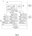
- Fig. 5 is a detailed block diagram of a second embodiment of the system 1 for testing of a 1-to-many wireless power transmitter device 20.
- a main probe device 31 which has a wireless power receiver 32a', receiver coil 34a' and load 36a', and is under direct operative control by the master controller 42 of the master test device 40 to perform a wireless power transfer test procedure 120a upon any one of the wireless power transmitters 22a-n of the wireless power transmitter device 20 under test.
- the load 36' for the probe device 31 may alternatively be located in the master test device 40, or even in the master controller 42 thereof, as is indicated at 36a".
- the number of slave test devices 30a-n used in this invention may be an arbitrary number of slave test devices, including a case where only a single slave test device is used.
- at least two slave test devices are used, wherein in such a case the locution "a number of slave test devices" will mean "a plurality of slave test devices".
- the locution "a number of slave test devices” will mean "a plurality of slave test devices”.
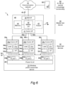
- Fig. 6 is a detailed block diagram of a third embodiment of the system 1 for testing of a 1-to-many wireless power transmitter device 20.
- the master controller 42 of the master test device 40 is further configured for communicating with remote artificial intelligence, machine learning or central knowledge functionality 60 to transmit information to the remote artificial intelligence, machine learning or central knowledge functionality 60, which includes remote computing resources 62.
- the transmitted information may include or be derived from the respective result data 125an obtained from the slave test devices 30a-n, including the main probe device 31 when applicable. This will accelerate product development as well as trouble shooting for a product or series of products as a whole, since it may make it easier to detect and conclude on errors, anomalies or malfunctions that only occur infrequently and/or only for a fraction of the product samples.
- the master controller 42 of the master test device 40 may be further configured for communicating with the remote artificial intelligence, machine learning or central knowledge functionality 60 to receive information from the remote artificial intelligence, machine learning or central knowledge functionality 60.
- the received information may serve for updating one, some or all of the respective test procedures 120a-n of the slave test devices 30a-n, and/or the main probe device 31 when applicable. This may allow further refinements of the test procedures of the system 1 and, in particular, gain from knowledge or experience that has been obtained from other tests and test systems performed around the world.
- the master test device 40 comprises a network communication interface 46
- such network communication interface 46 may also represent the aforementioned output unit 43.
- the output 45 which is based on the respective result data 125a-n obtained from the slave test devices 30a-n, and from the main probe device 31 when applicable, may be made by communicating the output 45 to a network resource over the network communication interface 46.
- a first example is testing of communication quality during wireless power transfer.
- at least one of the test procedures 120a-n of the slave test devices 30a-n involves testing or measuring a parameter indicative of a quality of inductive communication between a slave test device 30a-n and a wireless power transmitter 22an of the wireless power transmitter device 20 under test, according to a communication protocol (for instance pursuant to Qi) for controlling a wireless power transfer session.
- a communication protocol for instance pursuant to Qi
- a second example is testing of magnetic field strength.
- at least one of the test procedures 120a-n of the slave test devices 30a-n involves testing or measuring a parameter indicative of a magnetic field strength during wireless power transfer by a wireless power transmitter 22a-n of the wireless power transmitter device 20 under test.
- a third example is testing of power transfer efficiency.
- at least one of the test procedures 120a-n of the slave test devices 30a-n involves testing or measuring a parameter indicative of the efficiency of wireless power transfer by a wireless power transmitter 22a-n of the wireless power transmitter device 20 under test.
- a fourth example is testing of temperature. Accordingly, at least one of the test procedures 120a-n of the slave test devices 30a-n involves testing or measuring a parameter indicative of a temperature during wireless power transfer by a wireless power transmitter 22a-n of the wireless power transmitter device 20 under test.
- a fifth example is testing of the ability to detect a foreign object.
- at least one of the test procedures 120a-n of the slave test devices 30a-n involves testing or measuring a capability of detecting the presence of a foreign object during wireless power transfer by a wireless power transmitter 22a-n of the wireless power transmitter device 20 under test.
- a sixth example is to move the physical position of one or more of the slave test devices 30a-n with respect to any of the wireless power transmitters 22a-n and verify the impact of such physical movements in various performance indicators.
- test procedures performable by slave test devices in the system according to the present invention.
- Fig. 9 is a schematic flowchart diagram of a method 200 for testing of 1-to-many wireless power transfer equipment, such as the wireless power transmitter device 20 as described above.
- the method is essentially the procedural equivalent of the functionality performed by the system 1 and any or all of its embodiments as described in this document.
- a first step 210 involves providing a number of slave test devices 30a-n.
- a second step 220 involves providing a master test device 40 in communicative connection with the slave test devices 30a-n.
- a third step 230 involves arranging each slave test device 30a-n in a position suitable for receiving power from a respective one of the wireless power transmitters 22a-n of the wireless power transfer equipment 20 under test.
- a fourth step 240 involves commanding (also see 110a-n in Fig. 7 and Fig. 8 ), by the master test device 40, the slave test devices 30a-n to perform respective test procedures 120a-n upon the respective wireless power transmitters 22a-n.
- a sixth step 260 then involves providing (also see 170 in Fig. 7 and Fig. 8 ) an output 45 by the master test device 40, the output 45 being based on the respective result data 125a-n obtained from the slave test devices 30a-n.
- the method 200 may comprise any functional step that corresponds to the functionality of the system 1, master test device 40, slave test devices 30a-n and main probe device 31 as described throughout this document.
- the wireless power transmitter device 20 under test (the DUT) comprises a three-device charger.
- the particular test concepts in these examples are:
- the master test device 40 contains highly accurate compliance test equipment that has any needed functionality and measurements built in. Then there are two slave test devices used to enable all three charging spots on the DUT simultaneously.
- the slave test devices have the following features/functions that can be controlled by the master test device 40 through instructions over their data connection:
- the master test device 40 can perform all functions and features that are required from compliance test equipment.
- the master test device 40 can emulate various wireless power receiver reference designs and can do this by moving through different operating points MOP-1 through MOP-n.
- An operating point can be seen as a combination of DC voltage and DC current on the receiver.
- One way of changing operating points is by changing the load resistance; another way is by changing the DC voltage.
- the collection of all operating points that a specific Reference Receiver can operate under is called the Operating Space for that receiver.
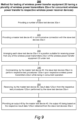
- Test concept A is illustrated further in Figs. 10A-B which will be described in more detail below.
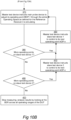
- Test concept B can essentially be the same with the exception that the master test device 40 does not measure BER but instead measures FOD performance and can be instructed to adjust the settings relevant for FOD testing.
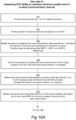
- Figs. 10A-B hence illustrate an exemplifying use case A which pertains to assessing the ability of the wireless power transmitter device 20 under test (the DUT) to maintain a minimum quality level of the in-band communication channel, pursuant to the requirements of the Qi standard.
- the wireless power transmitter device 20 has three wireless power transmitters 22a-n.
- the system 1 uses two slave test devices 30a-n (referred to as slave test devices 1 & 2) and one main probe device 31 for testing the wireless power transmitter device 20 and its three wireless power transmitters 22a-n.
- an operator i.e. user connects slave test devices 1 & 2 to the master test device 40.
- the master test device 40 informs the operator at 320 to make sure that no devices or foreign objects are placed on the DUT.
- the master test device 40 configures the main probe device, slave test device 1 and slave test device 2 to proceed (once positioned on the DUT) to a power transfer phase at operating points MOP-1, AOP-1 and AOP-2, respectively.
- the master test device 40 then, at 340, instructs the operator to position the main probe device on the charge surface of the DUT and wait until power transfer is in progress. Furthermore, at 350, the master test device 40 instructs the operator to position the slave test devices 1 & 2 on the charge surface of the DUT and let them proceed through the protocol until power transfer is in progress.
- the master test device 40 sets the main probe device to continuously measure and report the bit error rate (BER) of the communication channel on the main probe device.
- BER bit error rate
- the master test device 40 instructs the main probe device to adjust its operating point MOP-1 through the entire Operating Space, as defined for the Reference Receiver it is emulating.
- the master test device 40 is for testing of a wireless power transmitter device 20 of a type that has a plurality of wireless power transmitters 22a-n adapted for wireless power transfer, and comprises a local data communication interface 41, a master controller 42, and an output unit 43.
- the master test device 40 is configured to communicate with a plurality of slave test devices 30a-n via the local data communication interface 41.
- the master controller 42 of the master test device 40 is configured to command 1 10a-n the slave test devices 30a-n to perform respective wireless power transfer test procedures 120a-n upon respective ones of the wireless power transmitters 22a-n of the wireless power transmitter device 20 under test, to receive 140a-n result data 125a-n from the respective test procedures 120a-n performed by the slave test devices 30a-n, and to provide 170 an output 45 by the output unit 43 of the master test device 40, the output 45 being based on the respective result data 125a-n obtained from the slave test devices 30a-n.
- the slave test device 30b is for testing of a wireless power transmitter device 20 of a type that has a plurality of wireless power transmitters 22a-n adapted for wireless power transfer.
- the slave test device 30b comprises a local data communication interface 38b being adapted for data communication with a master test device 40, a wireless power receiver 32b, and a local controller 37b configured for performing a wireless power transfer test procedure 120b pertaining to any of the wireless power transmitters 22a-n of the wireless power transmitter device 20 under test.
- the slave test device 30b is configured to communicate via its local data communication interface 38b with the master test device 40.
- the controller 37b of the slave test device 30b is configured to receive a command 110b from the master test device 40, perform the wireless power transfer test procedure 120b upon one of the wireless power transmitters 22a-n, generate result data 125b from the performance of the wireless power transfer test procedure 120b, and transmit 130b the result data 125b to the master test device 40.
- the master test device 40 and the slave test device 30b can, of course, be included in the system 1 as described above.
Landscapes
- Engineering & Computer Science (AREA)
- Computer Networks & Wireless Communication (AREA)
- Power Engineering (AREA)
- Physics & Mathematics (AREA)
- Electromagnetism (AREA)
- Signal Processing (AREA)
- General Physics & Mathematics (AREA)
- Mobile Radio Communication Systems (AREA)
- Selective Calling Equipment (AREA)
Claims (15)
- System (1) zum Testen eines Geräts für eine drahtlose Leistungsübertragung (20), das mehrere drahtlose Leistungssender (22a-n) umfasst, die für eine gleichzeitige drahtlose Leistungsübertragung an jeweilige drahtlose Leistungsempfängervorrichtungen (10a, 10a', 10d) ausgelegt sind, wobei das System (1) umfasst:eine Master-Testvorrichtung (40) miteiner lokalen Datenkommunikationsschnittstelle (41),einer Master-Steuereinheit (42) undeiner Ausgabeeinheit (43); undeine Anzahl von Slave-Testvorrichtungen (30a-n), wobei jede Slave-Testvorrichtung Folgendes besitzt:eine lokale Datenkommunikationsschnittstelle (38a-n), die für eine Datenkommunikation mit der Master-Testvorrichtung (40) ausgelegt ist,einen drahtlosen Leistungsempfänger (32a-n) undeine lokale Steuereinheit (37a-b), die konfiguriert ist, ein Testverfahren für eine drahtlose Leistungsübertragung (120a-n) an einem der drahtlosen Leistungssender (22a-n) des Geräts für eine drahtlose Leistungsübertragung (20) im Test auszuführen;wobei die Master-Testvorrichtung (40) konfiguriert ist, über ihre lokale Datenkommunikationsschnittstelle (41) mit den Slave-Testvorrichtungen (30a-n) zu kommunizieren; undwobei die Master-Steuereinheit (42) der Master-Testvorrichtung (40) konfiguriert ist zum:Anweisen (110a-n) der Slave-Testvorrichtungen (30a-n), ihr jeweiliges Testverfahren (120a-n) an jeweiligen der drahtlosen Leistungssender (22a-n) des Geräts für eine drahtlose Leistungsübertragung (20) auszuführen, während sie in gleichzeitigem Betrieb im Test sind,Empfangen (140a-n) von Ergebnisdaten (125a-n) von den jeweiligen Testverfahren (120a-n), die durch die Slave-Testvorrichtungen (30a-n) ausgeführt werden, undBereitstellen (170) einer Ausgabe (45) durch die Ausgabeeinheit (43) der Master-Testvorrichtung (40), wobei die Ausgabe (45) auf den jeweiligen Ergebnisdaten (125a-n) beruht, die von den Slave-Testvorrichtungen (30a-n) erhalten werden.
- System (1) nach Anspruch 1, wobei die Master-Steuereinheit (42) der Master-Testvorrichtung (40) ferner konfiguriert ist zum:Analysieren (150) der jeweiligen Ergebnisdaten (125a-n), die von den Slave-Testvorrichtungen (30a-n) erhalten werden; undAbleiten eines kombinierten Testergebnisses, das ein gesamtes Testergebnis für das Gerät für eine drahtlose Leistungsübertragung (20) im Test repräsentiert.
- System (1) nach Anspruch 1 oder 2, wobei die Master-Steuereinheit (42) der Master-Testvorrichtung (40) ferner konfiguriert ist zum:Analysieren (150) der jeweiligen Ergebnisdaten (125a-n), die von den Slave-Testvorrichtungen (30a-n) erhalten werden; undAbleiten eines individuellen Testergebnisses für einen bestimmten drahtlosen Leistungssender (22a) des Geräts für eine drahtlose Leistungsübertragung (20) im Test.
- System (1) nach einem vorhergehenden Anspruch, wobei die Master-Steuereinheit (42) der Master-Testvorrichtung (40) ferner konfiguriert ist zum:Bewirken, dass die Slave-Testvorrichtungen (30a-n) ihre jeweiligen Testverfahren (120a-n) iterativ ausführen, so dass das Testverfahren (120a) eines ersten bestimmten drahtlosen Leistungssenders (22a) des Geräts für eine drahtlose Leistungsübertragung (20) im Test mit einer iterativen Änderung eines Testparameters ausgeführt wird, während das Testverfahren (120b) eines zweiten bestimmten drahtlosen Leistungssenders (22b) des Geräts für eine drahtlose Leistungsübertragung (20) im Test mit keiner solchen Änderung des Testparameters ausgeführt wird;Analysieren (150) der jeweiligen Ergebnisdaten (125a-n), die von den Slave-Testvorrichtungen (30a-n) erhalten werden, um die Testergebnisse des ersten und des zweiten bestimmten drahtlosen Leistungssenders (22a, 22b) zu korrelieren; undIdentifizieren aus der Korrelation des ersten bestimmten drahtlosen Leistungssenders (22a) als die Ursache des Testergebnisses des zweiten bestimmten drahtlosen Leitungssenders (22b).
- System (1) nach einem vorhergehenden Anspruch, wobei die Master-Steuereinheit (42) der Master-Testvorrichtung (40) ferner konfiguriert ist zum:Analysieren (150) der jeweiligen Ergebnisdaten (125a-n), die von den Slave-Testvorrichtungen (30a-n) erhalten werden;Bestimmen (160) einer Änderung eines Testverfahrens (120a-n) einer oder mehrerer der Slave-Testvorrichtungen (30a-n); undBewirken (162), dass die eine oder die mehreren Slave-Testvorrichtungen (30a-n) ihr geändertes Testverfahren (120a-n) ausführen.
- System (1) nach einem vorhergehenden Anspruch, wobei die Master-Steuereinheit (42) der Master-Testvorrichtung (40) ferner konfiguriert ist, eine Anwenderrückmeldung oder eine durch das Gerät für die drahtlose Leistungsübertragung (20) gegebene Angabe zu testen oder zu messen, wenn ein Problemzustand in Verbindung mit der Übertragung drahtloser Leistung durch einen der drahtlosen Leistungssender (22a-n) auftritt, der durch eine der Slave-Testvorrichtung (30a-n), die ihr Testverfahren (120a-n) ausführt, detektiert wird.
- System (1) nach einem vorhergehenden Anspruch, das ferner umfasst:
eine Sondenvorrichtung (31) mit einem drahtlosen Leistungsempfänger (32a') und die unter einer direkten Betriebssteuerung durch die Master-Steuereinheit (42) der Master-Testvorrichtung (30) steht, um ein Testverfahren einer drahtlosen Leistungsübertragung (120a) an einem der drahtlosen Leistungssender (22a-n) des Geräts für eine drahtlose Leistungsübertragung (20) im Test auszuführen. - System (1) nach einem vorhergehenden Anspruch, wobei die Master-Testvorrichtung (240) ferner eine Netzkommunikationsschnittstelle (46) umfasst, wobei die Master-Steuereinheit (42) der Master-Testvorrichtung (40) ferner konfiguriert ist, mit einer entfernten künstliche Intelligenz, einer Funktionalität eines maschinellen Lernens oder eines zentralen Wissens (50) zu kommunizieren, um eines oder beides des Folgenden auszuführen:a) Senden von Informationen an die entfernte künstliche Intelligenz, die Funktionalität des maschinellen Lernens oder des zentralen Wissens (60), wobei die Informationen die jeweiligen Ergebnisdaten (125a-n), die von den Slave-Testvorrichtungen (30a-n) erhalten werden, enthalten oder von diesen abgeleitet sind; undb) Empfangen von Informationen von der entfernten künstlichen Intelligenz, der Funktionalität des maschinellen Lernens oder eines zentralen Wissens (60), wobei die Informationen dazu dienen, eine, einige oder alle der jeweiligen Testverfahren (120a-n) der Slave-Testvorrichtungen (30a-n) zu aktualisieren.
- System (1) nach einem vorhergehenden Anspruch, wobei mindestens eines der Testverfahren (120a-n) der Slave-Testvorrichtungen (30a-n) das Testen oder Messen eines Parameters, der eine Qualität einer induktiven Kommunikation zwischen einer Slave-Testvorrichtung (20a-n) und einem drahtlosen Leistungssender (22a-n) des Geräts für eine drahtlose Leistungsübertragung (20) im Test angibt, gemäß einem Kommunikationsprotokoll zum Steuern einer drahtlosen Leistungsübertragungssitzung beinhaltet.
- System (1) nach einem vorhergehenden Anspruch, wobei mindestens eines der Testverfahren (120a-n) der Slave-Testvorrichtungen (30a-n) das Testen oder Messen eines Parameters, der eine Magnetfeldstärke während einer drahtlosen Leistungsübertragung durch einen drahtlosen Leistungssender (22a-n) des Geräts für eine drahtlose Leistungsübertragung (20) im Test angibt, beinhaltet.
- System (1) nach einem vorhergehenden Anspruch, wobei mindestens eines der Testverfahren (120a-n) der Slave-Testvorrichtungen (30a-n) das Testen oder Messen eines Parameters, der eine Effizienz der drahtlosen Leistungsübertragung durch einen drahtlosen Leistungssender (22a-n) des Geräts für eine drahtlose Leistungsübertragung (20) im Test angibt, beinhaltet.
- System (1) nach einem vorhergehenden Anspruch, wobei mindestens eines der Testverfahren (120a-n) der Slave-Testvorrichtungen (30a-n) das Testen oder Messen eines Parameters, der eine Temperatur während der drahtlosen Leistungsübertragung durch einen drahtlosen Leistungssender (22a-n) des Geräts für eine drahtlose Leistungsübertragung (20) im Test angibt, beinhaltet.
- System (1) nach einem vorhergehenden Anspruch, wobei mindestens eines der Testverfahren (120a-n) der Slave-Testvorrichtungen (30a-n) das Testen oder Messen einer Fähigkeit des Detektierens der Anwesenheit eines fremden Objekts während der drahtlosen Leistungsübertragung durch einen drahtlosen Leistungssender (22a-n) des Geräts für eine drahtlose Leistungsübertragung (20) im Test beinhaltet.
- Verfahren (200) zum Testen eines Geräts für die drahtlose Leistungsübertragung (20), das mehrere drahtlose Leistungssender (22a-n) umfasst, die für eine gleichzeitige drahtlose Leistungsübertragung an jeweilige drahtlose Leistungsempfängervorrichtungen (10a, 10a', 10d) ausgelegt sind, wobei das Verfahren (200) umfasst:Bereitstellen (210) einer Anzahl von Slave-Testvorrichtungen (30a-n);Bereitstellen (210) einer Master-Testvorrichtung (40) in kommunikativer Verbindung mit den Slave-Testvorrichtungen (30a-n);Anordnen (230) jeder Slave-Testvorrichtung (30a-n) in einer Position, die zum Empfangen von Leistung von einem jeweiligen der drahtlosen Leistungssender (22a-n) des Geräts für eine drahtlose Leistungsübertragung (20) im Test geeignet ist;Anweisen (240; 110a-n) durch die Master-Testvorrichtung (40) der Slave-Testvorrichtungen (30a-n), jeweilige Testverfahren (120a-n) an dem jeweiligen drahtlosen Leistungssender (22a-n) auszuführen, während sie in gleichzeitigem Betrieb sind;Empfangen (250; 140a-n) durch die Master-Testvorrichtung (40) von Ergebnisdaten (125a-n) von den jeweiligen Testverfahren (120a-n), die durch die Slave-Testvorrichtungen (30a-n) ausgeführt werden; undBereitstellen (260; 170) einer Ausgabe (45) durch die Master-Testvorrichtung (40), wobei die Ausgabe (45) auf den jeweiligen Ergebnisdaten (125a-n) beruht, die von den Slave-Testvorrichtungen (30a-n) erhalten werden.
- Master-Testvorrichtung (40) zum Testen eines Geräts für die drahtlose Leistungsübertragung (20), das mehrere drahtlose Leistungssender (22a-n), die für eine gleichzeitige drahtlose Leistungsübertragung an jeweilige drahtlose Leistungsempfängervorrichtungen (10a, 10a', 10d) ausgelegt sind, umfasst, wobei die Master-Testvorrichtung (40) umfasst:eine lokale Datenkommunikationsschnittstelle (41);eine Master-Steuereinheit (42); undeine Ausgabeeinheit (43),wobei die Master-Testvorrichtung (40) konfiguriert ist, mit mehreren Slave-Testvorrichtungen (30a-n) über die lokale Datenkommunikationsschnittstelle (41) zu kommunizieren; undwobei die Master-Steuereinheit (42) der Master-Testvorrichtung (40) konfiguriert ist zum:Anweisen (110a-n) der Slave-Testvorrichtungen (30a-n), jeweilige Testverfahren für eine drahtlose Leistungsübertragung (120a-n) an jeweiligen der drahtlosen Leistungssender (22a-n) des Geräts für eine drahtlose Leistungsübertagung (20) auszuführen, während sie in gleichzeitigem Betrieb im Test sind,Empfangen (140a-n) von Ergebnisdaten (125a-n) von den jeweiligen Testverfahren (120a-n), die durch die Slave-Testvorrichtungen (30a-n) ausgeführt werden, undBereitstellen (170) einer Ausgabe (45) durch die Ausgabeeinheit (43) der Master-Testvorrichtung (40), wobei die Ausgabe (45) auf den jeweiligen Ergebnisdaten (125a-n), die von den Slave-Testvorrichtungen (30a-n) erhalten werden, beruht.
Applications Claiming Priority (2)
| Application Number | Priority Date | Filing Date | Title |
|---|---|---|---|
| EP20216532.0A EP4020758A1 (de) | 2020-12-22 | 2020-12-22 | System, master-testvorrichtung, slave-testvorrichtung und verfahren zum testen von drahtlosen leistungsübertragungsvorrichtungen mit mehreren drahtlosen leistungssendern |
| PCT/EP2021/085740 WO2022136027A1 (en) | 2020-12-22 | 2021-12-14 | System, master test device, a slave test device and method for testing of wireless power transfer equipment having a plurality of wireless power transmitters |
Publications (3)
| Publication Number | Publication Date |
|---|---|
| EP4038720A1 EP4038720A1 (de) | 2022-08-10 |
| EP4038720B1 true EP4038720B1 (de) | 2023-06-07 |
| EP4038720C0 EP4038720C0 (de) | 2023-06-07 |
Family
ID=73856836
Family Applications (2)
| Application Number | Title | Priority Date | Filing Date |
|---|---|---|---|
| EP20216532.0A Withdrawn EP4020758A1 (de) | 2020-12-22 | 2020-12-22 | System, master-testvorrichtung, slave-testvorrichtung und verfahren zum testen von drahtlosen leistungsübertragungsvorrichtungen mit mehreren drahtlosen leistungssendern |
| EP21836533.6A Active EP4038720B1 (de) | 2020-12-22 | 2021-12-14 | System, master-testvorrichtung und verfahren zum testen von drahtlosen leistungsübertragungsvorrichtungen mit mehreren drahtlosen leistungssendern |
Family Applications Before (1)
| Application Number | Title | Priority Date | Filing Date |
|---|---|---|---|
| EP20216532.0A Withdrawn EP4020758A1 (de) | 2020-12-22 | 2020-12-22 | System, master-testvorrichtung, slave-testvorrichtung und verfahren zum testen von drahtlosen leistungsübertragungsvorrichtungen mit mehreren drahtlosen leistungssendern |
Country Status (6)
| Country | Link |
|---|---|
| US (1) | US11675022B2 (de) |
| EP (2) | EP4020758A1 (de) |
| JP (1) | JP7318121B2 (de) |
| KR (1) | KR102617844B1 (de) |
| CN (1) | CN115136450A (de) |
| WO (1) | WO2022136027A1 (de) |
Families Citing this family (7)
| Publication number | Priority date | Publication date | Assignee | Title |
|---|---|---|---|---|
| BR112022015090A2 (pt) * | 2020-01-30 | 2022-11-16 | Idac Holdings Inc | Método para uso em uma unidade de transmissão/recepção sem fio, e, dispositivo de unidade de recepção/transmissão sem fio |
| GB2605703B (en) * | 2022-04-04 | 2024-05-08 | Rolls Royce Plc | Methods and systems of monitoring a condition of a component of a gas turbine engine |
| US12321249B2 (en) | 2022-11-10 | 2025-06-03 | Intelligent Memory Limited | Systems and methods for reducing error log required space in semiconductor testing |
| US12099424B2 (en) * | 2022-11-10 | 2024-09-24 | Intelligent Memory Limited | Apparatus, systems, and methods for dynamically reconfigured semiconductor tester for volatile and non-volatile memories |
| US12374417B2 (en) | 2022-11-10 | 2025-07-29 | Intelligent Memory Limited | Apparatus, systems, and methods for dynamically reconfigured semiconductor tester for volatile and non-volatile memories |
| US12531133B2 (en) | 2022-11-10 | 2026-01-20 | Intelligent Memory Limited | Systems and methods for reducing error log required space at low temperatures |
| CN119922597B (zh) * | 2023-10-31 | 2026-01-02 | 深圳市三诺数字科技有限公司 | 一种设备分流测试方法、装置、计算机设备及存储介质 |
Citations (1)
| Publication number | Priority date | Publication date | Assignee | Title |
|---|---|---|---|---|
| EP3542475B1 (de) * | 2016-10-12 | 2020-03-04 | NOK9 ip AB | Testsystem zur verwendung beim testen eines drahtlosen stromtransfers sowie zugehörige testvorrichtung und verfahren |
Family Cites Families (12)
| Publication number | Priority date | Publication date | Assignee | Title |
|---|---|---|---|---|
| JP2001359142A (ja) | 2000-06-12 | 2001-12-26 | Matsushita Electric Ind Co Ltd | 無線基地局試験装置及び無線基地局試験方法 |
| KR101824766B1 (ko) * | 2012-03-28 | 2018-02-01 | 후지쯔 가부시끼가이샤 | 무선 전력 전송 시스템 및 무선 전력 전송 방법 |
| JP2015042092A (ja) | 2013-08-22 | 2015-03-02 | キヤノン株式会社 | 送電装置及びその制御方法、コンピュータプログラム |
| CN106464022A (zh) | 2014-05-22 | 2017-02-22 | 富士通株式会社 | 受电器、无线电力传输系统以及kQ值计算方法 |
| EP3547487B1 (de) | 2018-03-29 | 2020-03-25 | NOK9 ip AB | Prüfungsvorrichtung zum prüfen einer vorrichtung zur drahtlosen stromübertragung und zugehöriges verfahren |
| WO2019203420A1 (ko) * | 2018-04-18 | 2019-10-24 | 엘지전자 주식회사 | 무선전력 전송 시스템에서 이물질 검출을 수행하는 장치 및 방법 |
| EP3576307B1 (de) * | 2018-06-01 | 2023-10-25 | ElectDis AB | Sondenvorrichtung, analysevorrichtung, system und verfahren zum testen von ausrüstung zur drahtlosen stromversorgung |
| JP7329345B2 (ja) | 2019-03-27 | 2023-08-18 | 日本信号株式会社 | 非接触給電システム及び送電装置 |
| EP3829071B1 (de) * | 2019-11-29 | 2023-07-19 | ElectDis AB | Verfahren, vorrichtungen und testsystem zur datenübertragung während der energieübertragung in einem drahtlosen energieübertragungssystem |
| US11837883B2 (en) | 2020-01-21 | 2023-12-05 | Aira, Inc. | Multi-coil wireless charger validation |
| US11444492B2 (en) * | 2021-02-10 | 2022-09-13 | Nucurrent, Inc. | Wireless power transfer systems for kitchen appliances |
| US11967836B2 (en) * | 2021-09-07 | 2024-04-23 | Apple Inc. | Harmonic current monitoring in a wireless power system |
-
2020
- 2020-12-22 EP EP20216532.0A patent/EP4020758A1/de not_active Withdrawn
-
2021
- 2021-12-14 EP EP21836533.6A patent/EP4038720B1/de active Active
- 2021-12-14 KR KR1020227017278A patent/KR102617844B1/ko active Active
- 2021-12-14 JP JP2022521001A patent/JP7318121B2/ja active Active
- 2021-12-14 US US17/642,452 patent/US11675022B2/en active Active
- 2021-12-14 CN CN202180005823.1A patent/CN115136450A/zh active Pending
- 2021-12-14 WO PCT/EP2021/085740 patent/WO2022136027A1/en not_active Ceased
Patent Citations (1)
| Publication number | Priority date | Publication date | Assignee | Title |
|---|---|---|---|---|
| EP3542475B1 (de) * | 2016-10-12 | 2020-03-04 | NOK9 ip AB | Testsystem zur verwendung beim testen eines drahtlosen stromtransfers sowie zugehörige testvorrichtung und verfahren |
Also Published As
| Publication number | Publication date |
|---|---|
| WO2022136027A1 (en) | 2022-06-30 |
| KR102617844B1 (ko) | 2023-12-27 |
| JP7318121B2 (ja) | 2023-07-31 |
| EP4020758A1 (de) | 2022-06-29 |
| US20230140156A1 (en) | 2023-05-04 |
| US11675022B2 (en) | 2023-06-13 |
| JP2023502847A (ja) | 2023-01-26 |
| KR20220093139A (ko) | 2022-07-05 |
| CN115136450A (zh) | 2022-09-30 |
| EP4038720C0 (de) | 2023-06-07 |
| EP4038720A1 (de) | 2022-08-10 |
Similar Documents
| Publication | Publication Date | Title |
|---|---|---|
| EP4038720B1 (de) | System, master-testvorrichtung und verfahren zum testen von drahtlosen leistungsübertragungsvorrichtungen mit mehreren drahtlosen leistungssendern | |
| US20220163601A1 (en) | Testing system for use in testing of wireless power transfer, and an associated testing device and method | |
| CN106789423B (zh) | 交换机自动化测试装置及测试方法 | |
| US9419430B1 (en) | System for monitoring and modeling operation of a transformer | |
| US9841737B2 (en) | Automatic test system and method | |
| KR102615470B1 (ko) | 무선전력장치의 검사를 위한 시스템 및 방법 | |
| CN108885234B (zh) | 用于测试电气设备的适配器 | |
| CN104035020B (zh) | 可隔离信号干扰的半导体电路测试装置 | |
| KR20160107770A (ko) | Ees의 성능을 평가하는 시스템 및 방법 | |
| US11959992B2 (en) | Methods and systems for providing a secondary reference for evaluation of wireless power measuring accuracy, and for evaluating a power measuring accuracy of a wireless power measurement device under test | |
| CN113008221A (zh) | 天线姿态的测试设备、方法及系统 | |
| CN112929102B (zh) | Mimo无线终端射频性能诊断方法、装置及相关设备 | |
| TWI491888B (zh) | 可隔離信號干擾之半導體電路測試裝置 | |
| KR20240113184A (ko) | 전력용 차단기의 잔존 수명 정보를 제공하는 서버를 포함하는 전력용 차단기 관리 시스템 및 그 서버의 제어 방법 | |
| CN119986509A (zh) | 一种电池测量系统分析方法、装置、设备及存储介质 | |
| HK1257027B (en) | Adapters for testing electrical equipment |
Legal Events
| Date | Code | Title | Description |
|---|---|---|---|
| STAA | Information on the status of an ep patent application or granted ep patent |
Free format text: STATUS: UNKNOWN |
|
| STAA | Information on the status of an ep patent application or granted ep patent |
Free format text: STATUS: THE INTERNATIONAL PUBLICATION HAS BEEN MADE |
|
| PUAI | Public reference made under article 153(3) epc to a published international application that has entered the european phase |
Free format text: ORIGINAL CODE: 0009012 |
|
| STAA | Information on the status of an ep patent application or granted ep patent |
Free format text: STATUS: REQUEST FOR EXAMINATION WAS MADE |
|
| 17P | Request for examination filed |
Effective date: 20220310 |
|
| AK | Designated contracting states |
Kind code of ref document: A1 Designated state(s): AL AT BE BG CH CY CZ DE DK EE ES FI FR GB GR HR HU IE IS IT LI LT LU LV MC MK MT NL NO PL PT RO RS SE SI SK SM TR |
|
| REG | Reference to a national code |
Ref country code: DE Ref legal event code: R079 Ref document number: 602021002859 Country of ref document: DE Free format text: PREVIOUS MAIN CLASS: H02J0050120000 Ipc: H04B0017170000 |
|
| RIC1 | Information provided on ipc code assigned before grant |
Ipc: H04B 17/24 20150101ALI20221123BHEP Ipc: H04B 5/00 20060101ALI20221123BHEP Ipc: H02J 50/40 20160101ALI20221123BHEP Ipc: G01R 31/40 20200101ALI20221123BHEP Ipc: H02J 50/12 20160101ALI20221123BHEP Ipc: H04B 17/17 20150101AFI20221123BHEP |
|
| GRAP | Despatch of communication of intention to grant a patent |
Free format text: ORIGINAL CODE: EPIDOSNIGR1 |
|
| STAA | Information on the status of an ep patent application or granted ep patent |
Free format text: STATUS: GRANT OF PATENT IS INTENDED |
|
| DAV | Request for validation of the european patent (deleted) | ||
| DAX | Request for extension of the european patent (deleted) | ||
| INTG | Intention to grant announced |
Effective date: 20230103 |
|
| GRAS | Grant fee paid |
Free format text: ORIGINAL CODE: EPIDOSNIGR3 |
|
| GRAA | (expected) grant |
Free format text: ORIGINAL CODE: 0009210 |
|
| STAA | Information on the status of an ep patent application or granted ep patent |
Free format text: STATUS: THE PATENT HAS BEEN GRANTED |
|
| AK | Designated contracting states |
Kind code of ref document: B1 Designated state(s): AL AT BE BG CH CY CZ DE DK EE ES FI FR GB GR HR HU IE IS IT LI LT LU LV MC MK MT NL NO PL PT RO RS SE SI SK SM TR |
|
| REG | Reference to a national code |
Ref country code: GB Ref legal event code: FG4D |
|
| REG | Reference to a national code |
Ref country code: CH Ref legal event code: EP Ref country code: AT Ref legal event code: REF Ref document number: 1577940 Country of ref document: AT Kind code of ref document: T Effective date: 20230615 |
|
| REG | Reference to a national code |
Ref country code: DE Ref legal event code: R096 Ref document number: 602021002859 Country of ref document: DE |
|
| U01 | Request for unitary effect filed |
Effective date: 20230707 |
|
| U07 | Unitary effect registered |
Designated state(s): AT BE BG DE DK EE FI FR IT LT LU LV MT NL PT SE SI Effective date: 20230719 |
|
| REG | Reference to a national code |
Ref country code: LT Ref legal event code: MG9D |
|
| PG25 | Lapsed in a contracting state [announced via postgrant information from national office to epo] |
Ref country code: NO Free format text: LAPSE BECAUSE OF FAILURE TO SUBMIT A TRANSLATION OF THE DESCRIPTION OR TO PAY THE FEE WITHIN THE PRESCRIBED TIME-LIMIT Effective date: 20230907 Ref country code: ES Free format text: LAPSE BECAUSE OF FAILURE TO SUBMIT A TRANSLATION OF THE DESCRIPTION OR TO PAY THE FEE WITHIN THE PRESCRIBED TIME-LIMIT Effective date: 20230607 |
|
| PG25 | Lapsed in a contracting state [announced via postgrant information from national office to epo] |
Ref country code: RS Free format text: LAPSE BECAUSE OF FAILURE TO SUBMIT A TRANSLATION OF THE DESCRIPTION OR TO PAY THE FEE WITHIN THE PRESCRIBED TIME-LIMIT Effective date: 20230607 Ref country code: HR Free format text: LAPSE BECAUSE OF FAILURE TO SUBMIT A TRANSLATION OF THE DESCRIPTION OR TO PAY THE FEE WITHIN THE PRESCRIBED TIME-LIMIT Effective date: 20230607 Ref country code: GR Free format text: LAPSE BECAUSE OF FAILURE TO SUBMIT A TRANSLATION OF THE DESCRIPTION OR TO PAY THE FEE WITHIN THE PRESCRIBED TIME-LIMIT Effective date: 20230908 |
|
| PG25 | Lapsed in a contracting state [announced via postgrant information from national office to epo] |
Ref country code: SK Free format text: LAPSE BECAUSE OF FAILURE TO SUBMIT A TRANSLATION OF THE DESCRIPTION OR TO PAY THE FEE WITHIN THE PRESCRIBED TIME-LIMIT Effective date: 20230607 |
|
| PG25 | Lapsed in a contracting state [announced via postgrant information from national office to epo] |
Ref country code: IS Free format text: LAPSE BECAUSE OF FAILURE TO SUBMIT A TRANSLATION OF THE DESCRIPTION OR TO PAY THE FEE WITHIN THE PRESCRIBED TIME-LIMIT Effective date: 20231007 |
|
| U20 | Renewal fee for the european patent with unitary effect paid |
Year of fee payment: 3 Effective date: 20231215 |
|
| PG25 | Lapsed in a contracting state [announced via postgrant information from national office to epo] |
Ref country code: SM Free format text: LAPSE BECAUSE OF FAILURE TO SUBMIT A TRANSLATION OF THE DESCRIPTION OR TO PAY THE FEE WITHIN THE PRESCRIBED TIME-LIMIT Effective date: 20230607 Ref country code: SK Free format text: LAPSE BECAUSE OF FAILURE TO SUBMIT A TRANSLATION OF THE DESCRIPTION OR TO PAY THE FEE WITHIN THE PRESCRIBED TIME-LIMIT Effective date: 20230607 Ref country code: RO Free format text: LAPSE BECAUSE OF FAILURE TO SUBMIT A TRANSLATION OF THE DESCRIPTION OR TO PAY THE FEE WITHIN THE PRESCRIBED TIME-LIMIT Effective date: 20230607 Ref country code: IS Free format text: LAPSE BECAUSE OF FAILURE TO SUBMIT A TRANSLATION OF THE DESCRIPTION OR TO PAY THE FEE WITHIN THE PRESCRIBED TIME-LIMIT Effective date: 20231007 Ref country code: CZ Free format text: LAPSE BECAUSE OF FAILURE TO SUBMIT A TRANSLATION OF THE DESCRIPTION OR TO PAY THE FEE WITHIN THE PRESCRIBED TIME-LIMIT Effective date: 20230607 |
|
| PG25 | Lapsed in a contracting state [announced via postgrant information from national office to epo] |
Ref country code: PL Free format text: LAPSE BECAUSE OF FAILURE TO SUBMIT A TRANSLATION OF THE DESCRIPTION OR TO PAY THE FEE WITHIN THE PRESCRIBED TIME-LIMIT Effective date: 20230607 |
|
| REG | Reference to a national code |
Ref country code: DE Ref legal event code: R097 Ref document number: 602021002859 Country of ref document: DE |
|
| PLBE | No opposition filed within time limit |
Free format text: ORIGINAL CODE: 0009261 |
|
| STAA | Information on the status of an ep patent application or granted ep patent |
Free format text: STATUS: NO OPPOSITION FILED WITHIN TIME LIMIT |
|
| 26N | No opposition filed |
Effective date: 20240308 |
|
| PG25 | Lapsed in a contracting state [announced via postgrant information from national office to epo] |
Ref country code: MC Free format text: LAPSE BECAUSE OF FAILURE TO SUBMIT A TRANSLATION OF THE DESCRIPTION OR TO PAY THE FEE WITHIN THE PRESCRIBED TIME-LIMIT Effective date: 20230607 |
|
| PG25 | Lapsed in a contracting state [announced via postgrant information from national office to epo] |
Ref country code: MC Free format text: LAPSE BECAUSE OF FAILURE TO SUBMIT A TRANSLATION OF THE DESCRIPTION OR TO PAY THE FEE WITHIN THE PRESCRIBED TIME-LIMIT Effective date: 20230607 |
|
| REG | Reference to a national code |
Ref country code: IE Ref legal event code: MM4A |
|
| PG25 | Lapsed in a contracting state [announced via postgrant information from national office to epo] |
Ref country code: IE Free format text: LAPSE BECAUSE OF NON-PAYMENT OF DUE FEES Effective date: 20231214 |
|
| PG25 | Lapsed in a contracting state [announced via postgrant information from national office to epo] |
Ref country code: IE Free format text: LAPSE BECAUSE OF NON-PAYMENT OF DUE FEES Effective date: 20231214 |
|
| U20 | Renewal fee for the european patent with unitary effect paid |
Year of fee payment: 4 Effective date: 20241211 |
|
| PG25 | Lapsed in a contracting state [announced via postgrant information from national office to epo] |
Ref country code: CY Free format text: LAPSE BECAUSE OF FAILURE TO SUBMIT A TRANSLATION OF THE DESCRIPTION OR TO PAY THE FEE WITHIN THE PRESCRIBED TIME-LIMIT; INVALID AB INITIO Effective date: 20211214 |
|
| REG | Reference to a national code |
Ref country code: CH Ref legal event code: PL |
|
| PG25 | Lapsed in a contracting state [announced via postgrant information from national office to epo] |
Ref country code: CH Free format text: LAPSE BECAUSE OF NON-PAYMENT OF DUE FEES Effective date: 20241231 |
|
| PG25 | Lapsed in a contracting state [announced via postgrant information from national office to epo] |
Ref country code: TR Free format text: LAPSE BECAUSE OF FAILURE TO SUBMIT A TRANSLATION OF THE DESCRIPTION OR TO PAY THE FEE WITHIN THE PRESCRIBED TIME-LIMIT Effective date: 20230607 |
|
| PGFP | Annual fee paid to national office [announced via postgrant information from national office to epo] |
Ref country code: GB Payment date: 20251209 Year of fee payment: 5 |
|
| U20 | Renewal fee for the european patent with unitary effect paid |
Year of fee payment: 5 Effective date: 20251210 |