EP4037576B1 - Ausgabesysteme und vorrichtungen mit verstopfungsverhindernden sprühspitzen zur abgabe von zwei oder mehr flüssigkeiten, die miteinander reagieren - Google Patents
Ausgabesysteme und vorrichtungen mit verstopfungsverhindernden sprühspitzen zur abgabe von zwei oder mehr flüssigkeiten, die miteinander reagieren Download PDFInfo
- Publication number
- EP4037576B1 EP4037576B1 EP20790067.1A EP20790067A EP4037576B1 EP 4037576 B1 EP4037576 B1 EP 4037576B1 EP 20790067 A EP20790067 A EP 20790067A EP 4037576 B1 EP4037576 B1 EP 4037576B1
- Authority
- EP
- European Patent Office
- Prior art keywords
- distal end
- fluid
- spray
- dispensing cap
- end wall
- Prior art date
- Legal status (The legal status is an assumption and is not a legal conclusion. Google has not performed a legal analysis and makes no representation as to the accuracy of the status listed.)
- Active
Links
Images









Classifications
-
- A—HUMAN NECESSITIES
- A61—MEDICAL OR VETERINARY SCIENCE; HYGIENE
- A61B—DIAGNOSIS; SURGERY; IDENTIFICATION
- A61B17/00—Surgical instruments, devices or methods
- A61B17/00491—Surgical glue applicators
-
- A—HUMAN NECESSITIES
- A61—MEDICAL OR VETERINARY SCIENCE; HYGIENE
- A61B—DIAGNOSIS; SURGERY; IDENTIFICATION
- A61B17/00—Surgical instruments, devices or methods
- A61B17/00234—Surgical instruments, devices or methods for minimally invasive surgery
-
- A—HUMAN NECESSITIES
- A61—MEDICAL OR VETERINARY SCIENCE; HYGIENE
- A61M—DEVICES FOR INTRODUCING MEDIA INTO, OR ONTO, THE BODY; DEVICES FOR TRANSDUCING BODY MEDIA OR FOR TAKING MEDIA FROM THE BODY; DEVICES FOR PRODUCING OR ENDING SLEEP OR STUPOR
- A61M5/00—Devices for bringing media into the body in a subcutaneous, intra-vascular or intramuscular way; Accessories therefor, e.g. filling or cleaning devices, arm-rests
- A61M5/178—Syringes
- A61M5/19—Syringes having more than one chamber, e.g. including a manifold coupling two parallelly aligned syringes through separate channels to a common discharge assembly
-
- A—HUMAN NECESSITIES
- A61—MEDICAL OR VETERINARY SCIENCE; HYGIENE
- A61M—DEVICES FOR INTRODUCING MEDIA INTO, OR ONTO, THE BODY; DEVICES FOR TRANSDUCING BODY MEDIA OR FOR TAKING MEDIA FROM THE BODY; DEVICES FOR PRODUCING OR ENDING SLEEP OR STUPOR
- A61M5/00—Devices for bringing media into the body in a subcutaneous, intra-vascular or intramuscular way; Accessories therefor, e.g. filling or cleaning devices, arm-rests
- A61M5/178—Syringes
- A61M5/31—Details
-
- A—HUMAN NECESSITIES
- A61—MEDICAL OR VETERINARY SCIENCE; HYGIENE
- A61B—DIAGNOSIS; SURGERY; IDENTIFICATION
- A61B17/00—Surgical instruments, devices or methods
- A61B17/00234—Surgical instruments, devices or methods for minimally invasive surgery
- A61B2017/00292—Surgical instruments, devices or methods for minimally invasive surgery mounted on or guided by flexible, e.g. catheter-like, means
-
- A—HUMAN NECESSITIES
- A61—MEDICAL OR VETERINARY SCIENCE; HYGIENE
- A61B—DIAGNOSIS; SURGERY; IDENTIFICATION
- A61B17/00—Surgical instruments, devices or methods
- A61B17/00491—Surgical glue applicators
- A61B2017/00495—Surgical glue applicators for two-component glue
-
- A—HUMAN NECESSITIES
- A61—MEDICAL OR VETERINARY SCIENCE; HYGIENE
- A61B—DIAGNOSIS; SURGERY; IDENTIFICATION
- A61B17/00—Surgical instruments, devices or methods
- A61B17/00491—Surgical glue applicators
- A61B2017/00522—Sprayers
-
- A—HUMAN NECESSITIES
- A61—MEDICAL OR VETERINARY SCIENCE; HYGIENE
- A61M—DEVICES FOR INTRODUCING MEDIA INTO, OR ONTO, THE BODY; DEVICES FOR TRANSDUCING BODY MEDIA OR FOR TAKING MEDIA FROM THE BODY; DEVICES FOR PRODUCING OR ENDING SLEEP OR STUPOR
- A61M5/00—Devices for bringing media into the body in a subcutaneous, intra-vascular or intramuscular way; Accessories therefor, e.g. filling or cleaning devices, arm-rests
- A61M5/178—Syringes
- A61M5/31—Details
- A61M2005/3128—Incorporating one-way valves, e.g. pressure-relief or non-return valves
-
- A—HUMAN NECESSITIES
- A61—MEDICAL OR VETERINARY SCIENCE; HYGIENE
- A61M—DEVICES FOR INTRODUCING MEDIA INTO, OR ONTO, THE BODY; DEVICES FOR TRANSDUCING BODY MEDIA OR FOR TAKING MEDIA FROM THE BODY; DEVICES FOR PRODUCING OR ENDING SLEEP OR STUPOR
- A61M2206/00—Characteristics of a physical parameter; associated device therefor
- A61M2206/10—Flow characteristics
- A61M2206/12—Flow characteristics the flow being spirally in a plane, e.g. against a plane side of a membrane filter element
Definitions
- the present invention is generally related to medical devices for dispensing fluids, and is more specifically related to fluid dispensing systems having spray tips that dispense fluids used in medical and surgical procedures.
- MIS procedures differ from conventional surgical procedures in that a plurality of devices and/or surgical tools may be introduced into the body through cannulas and trocars that are inserted into small incisions. As a result, trauma to the body is greatly reduced, thereby decreasing the recovery time for patients.
- laparoscopic surgical procedures which are used to treat hernias, colon dysfunctions, gastroesophageal reflux disease, gallbladder disorders, etc.
- a patient undergoing a laparoscopic surgical procedure is able to return home within hours after undergoing surgery.
- One challenge presented when performing minimally invasive surgical procedures relates to controlling bleeding at the surgical site.
- a surgeon's access to a surgical site or surgical cavity is greatly reduced.
- tissue sealants may include fibrin sealants, which is comprised of thrombin, and a fibrinogen material, although other formulations are also available.
- fibrin sealants which is comprised of thrombin
- fibrinogen material although other formulations are also available.
- the individual components of the tissue sealants are stored separately in isolated reservoirs. The components are mixed together for the first time immediately prior to being applied to tissue. Once mixed, the components coagulate very quickly, yielding an adhesive gel within a short period of time (e.g., within 10-20 seconds). When considerable access to the application site is possible, the rapid coagulative properties of the tissue sealant are advantageous. However, the fast-acting properties of tissue sealants often clog the spray tips that are used for dispensing the components.
- US6835186B1 discusses a medical device for delivering volumetric quantities of a first and a second biochemically reactive fluid in which separate mechanical breakup units atomize the fluids.
- This device includes a fluid delivery device for laparoscopically delivering fluids having two feed conduits for delivering fluid to feed ports of the mechanical breakup units, the mechanical breakup units having two feed ports for receiving fluid from the feed conduits and directing such fluid into spin chambers and funneling portions having a sloped sidewall for directing fluid from the spin chambers through an exit port.
- This device is suitably dimensioned for creating a spray of two fluids with different viscosities such as fibrinogen and thrombin in such a manner that the thrombin spray cone encompasses the fibrinogen spray cone at a distance of about one inch from the exit port with a 0.5 cc/second flow rate to avoid depositing unreacted fibrinogen on a surface.
- US201 1/0253806A1 discusses a spraying device having a spray head for spraying, at least one component comprises at least one substance component duct , the component outlet of which leads out of a spray head tip.
- An annular duct for a pressurized gas surrounds the at least one component duct at least partially in the longitudinal direction and leads out of the spray head at the spray head tip.
- a pressurized gas supply duct is provided for introducing pressurized gas at the annular duct.
- the annular duct has a plurality of ribs, which divide the annular duct at least in the region of the spray head tip into pressurized gas outlet ducts that are separated from each other.
- a dispensing device 100 for spraying fluids may include one or more of the features disclosed in one or more embodiments of US 2018/0177978 to Spivey et al. , assigned to Ethicon LLC.
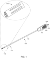
- the dispensing device 100 preferably includes a device housing 102 that contains a manifold (not shown) and two Luer-type connections 104, 106 that extend proximally from the device housing.
- the two Luer-type connectors 104, 106 may be connected to two syringes that contain respective fluids that react with one another.
- the dispensing device 100 desirably includes a brace 108 that is configured to connect the device housing 102 with a structure containing the two syringes.
- a first syringe may contain a first fluid and a second syringe may include a second fluid that reacts with the first fluid upon being sprayed from the dispensing device 100.
- the dispensing device 100 preferably includes an elongated shaft 110 (e.g., an elongated flexible or rigid tube) having a proximal end that is connected to the device housing 102.
- the elongated shaft 110 preferably extends distally from the device housing.
- the elongated shaft 110 contains two cannulas, which are desirably side-by-side and used to deliver two fluids to a connector 116 secured to a distal end 112 of the elongated shaft 110.
- a first fluid may be delivered through the first cannula and a second fluid may be delivered through the second cannula.
- the dispensing device 100 preferably includes an anti-clogging spray tip 114 that is secured to the distal end 112 of the elongated shaft 110 via a connector 116 ( FIG. 2 ). Upon being sprayed from the anti-clogging spray tip 114, the two fluids preferably react with one another.
- the anti-clogging spray tip 114 may be permanently secured to the distal end 112 of the elongated shaft 110. In one embodiment, the anti-clogging spray tip 114 may be releasably secured to the distal end 112 of the elongated shaft 110 so that a first spray tip (e.g., a used spray tip) may be detached and replaced by a second spray tip (e.g., a new spray tip) that may be releasably secured to the distal end of the shaft.
- a first spray tip e.g., a used spray tip
- a second spray tip e.g., a new spray tip
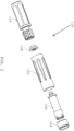
- the anti-clogging spray tip 114 ( FIG. 1 ) preferably includes various components that are assembled together for use in spraying two fluids from the distal end of the dispensing device 100 ( FIG. 1 ).
- the anti-clogging spray tip 114 preferably includes a gasket 118, a tip housing 120, an inner manifold 122, and a dispensing cap 124.
- the above-listed components of the anti-clogging spray tip 114 ( FIG. 1 ) are assembled together and the fully assembled anti-clogging spray tip 114 is secured to the distal end 112 of the tubular shaft 110 of the dispensing device 100 ( FIG. 1 ) via the connector 116.
- the connector 116 is not part of the anti-clogging spray tip 114, but is used for connecting the spray tip to a distal end of a shaft of a dispensing device.
- an anti-clogging spray tip may include a connector that is used for securing the spray tip to the distal end of a shaft of a dispensing device.
- the connector 116 preferably includes a tube-shaped body 126 that is secured to the distal end 112 of the elongated shaft 110 of the dispensing device ( FIG. 1 ).
- the connector 166 preferably includes a proximal end 128, a distal end 130, an inlet opening 132 at the proximal end 128 that is adapted to receive the distal end 112 of the elongated shaft 110 of the dispensing device 100 ( FIG. 1 ), and a connector flow chamber 134 that extends between the inlet opening 132 and an end wall 136 that defines an end of the connector flow chamber 134.
- the connector 116 preferably includes a first lumen 138 that extends between the connector flow chamber 134 and the distal end 130 of the connector.
- the first lumen 138 is adapted to receive a first cannula for a first fluid.
- the connector 116 preferably includes a second lumen 140 that extends between the connector flow chamber 134 and the distal end 130 of the connector.
- the second lumen 140 is adapted to receive a second cannula for a second fluid that reacts with the first fluid.
- the first and second fluids are preferably separated from one another as they pass through the connector 116.
- the first and second lumens 138, 140 are preferably side-by-side and are adapted to receive and seat respective first and second cannulas that extend through the tubular shaft 110 of the dispensing device 100 ( FIG. 1 ).
- the distal end 130 of the connector 116 preferably includes a first D-shaped exit port 144 that is aligned with a distal end of the first lumen 138, and a second D-shaped exit port 146 that is aligned with the distal end of the second lumen 140.
- the connector 116 desirably includes a connector dividing wall 141 that divides and spaces the first and second D-shaped exit ports 138, 140 from one another.
- the first and second D-shaped exit ports 144, 146 are adapted to receive first and second D-shaped attachment plugs projecting from a proximal face of the gasket 118 ( FIG.
- the two fluids are preferably maintained separate and apart from one another until they are sprayed from the dispensing cap 124 ( FIG. 2 ) located at the distal end of the anti-clogging spray tip 114 ( FIG. 1 ), whereupon the two fluids are mixed together for reacting with one another.
- the inlet opening 132 of the connector 116 provides access to the proximal end 128 ( FIG. 3A ) of the connector flow chamber 134, which is located at the proximal end of the tubular member 126 of the connector 116.
- the connector flow chamber 134 desirably terminates at the distal end wall 136.
- the first and second lumens 138, 140 are preferably formed in the distal end wall 136 and extend distally toward the respective D-shaped exits ports 144, 146 located at the distal end 130 of the connector 116.
- the first lumen 138 is adapted to receive a first cannula that contains a first fluid of a multiple component material and the second lumen 140 is adapted to receive a second cannula that contains a second fluid of the multiple component material.
- the gasket 118 preferably includes an annular plate 148 having a proximal face 150 that faces toward a proximal end of the anti-clogging spray tip 114 ( FIG. 2 ) and a distal face 152 that extends toward the distal end of the anti-clogging spray tip.
- the gasket 118 desirably includes a first D-shaped attachment plug 154 that is configured to be inserted into the first D-shaped exit port 144 at the distal end 130 of the connector 116 ( FIG. 3B ).
- the gasket 118 desirably includes a second D-shaped attachment plug 156 that is adapted to be inserted into the second D-shaped exit port 146 located at the distal end 130 of the connector 116 ( FIG. 3B ).
- the first and second D-shaped attachment plugs 154, 156 preferably have an outer dimension and configuration that closely matches the shape of the respective D-shaped exit ports 144, 146 located at the distal end 130 of the connector 116 for forming a press fit between the gasket 118 and the distal end of the connector 116.
- the gasket 118 preferably includes a first lumen 138' that extends through the first D-shaped plug 154 to the distal end face 152 of the annular plate 148.
- the gasket 118 desirably includes a second lumen 140' that extends through the second D-shaped plug 156 to the distal end face 152 of the annular plate 148.
- the first D-shaped attachment plug 154 is preferably inserted into the first D-shaped exit port 144 of the connector and the second D-shaped attachment plug 156 is inserted into the second D-shaped exit port 146 of the connector.
- the first lumen 138 extending through the connector is preferably in alignment with the first lumen 138' of the gasket 118 and the second lumen 140 extending through the connector 116 is preferably in alignment with the second lumen 140' of the gasket 118.
- the gasket 118 desirably includes a first pair of lateral struts 160A, 160B that extend across the first lumen 138'.
- the lateral struts 160A, 160B are preferably positioned between the proximal end of the D-shaped attachment plug 154 and the distal face 152 of the annular plate 148.
- the gasket 118 desirably includes a second pair of laterally extending struts 162A, 162B that extend across the second lumen 140' of the gasket 118.
- the second pair of laterally extending struts 162A, 162B is preferably positioned between the proximal end of the second D-shaped attachment plug 156 and the distal face 152 of the annular plug 148.
- the laterally extending struts 160A-160B and 162A-162B preferably seat the free ends of butterfly-shaped connectors that extend proximally from a proximal end of the inner manifold 122 ( FIG. 6A ).
- the distal face 152 of the annular plate 148 of the gasket 118 includes a first butterfly-shaped opening 161 that is aligned with the first lumen 138'.
- the first butterfly-shaped opening 161 is configured to receive a first butterfly-shaped connector that extends proximally from the inner manifold 122 ( FIG. 2 ).
- the distal face 152 of the annular plate 148 of the gasket 118 includes a second butterfly-shaped opening 163 that is aligned with the second lumen 140'.
- the second butterfly-shaped opening 163 is configured to receive a second butterfly-shaped connector that extends proximally from the inner manifold 122 ( FIG. 2 ).
- the tip housing 120 ( FIG. 2 ) of the anti-clogging spray tip preferably includes a tubular-shaped body 164 having a proximal end 166 and a distal end 168.
- the tubular-shaped body 164 of the tip housing 120 desirably includes an elongated conduit 170 that extends from a first opening 172 located at the proximal end 166 of the tubular member 164 and a second opening 174 located at the distal end 168 of the tubular member 164.
- the tubular member 164 has an inner surface 176 that surrounds the elongated conduit 170 and that extends from the proximal end 166 to the distal end 168 of the tubular member 164.
- the tip housing 120 preferably has internal threads 178 that are formed in the inner surface 176 of the tubular member 164.
- the internal threads 178 are preferably adjacent the proximal end 166 of the tubular member 164.
- the internal threads 168 are adapted to receive the external threads 142 at the distal end of the connector 116 ( FIG. 3A ) for securing the distal end of the connector 116 with the proximal end of the tip housing 120, with the gasket 118 ( FIG. 2 ) being positioned between the distal end of the connector 116 and the tip housing 120.
- the inner manifold 122 ( FIG. 2 ) preferably includes a tubular member 180 having a proximal end 182 and a distal end 184.
- the inner manifold 122 desirably includes an annular sealing flange 186 that is secured to the proximal end 182 of the tubular member 180.
- the annular sealing flange 186 desirably includes a proximal face 188 that is adapted to abut against the distal face 152 of the gasket 118 ( FIG. 4A ) when the components of the anti-clogging spray tip are assembled together.
- the inner manifold 122 desirably includes a first butterfly-shaped connector 190 that projects proximally from the proximal face 188 of the annular sealing flange 186.
- the inner manifold 122 desirably includes a second butterfly-shaped connector 192 that also projects proximally from the proximal face 188 of the annular sealing flange 186 of the inner manifold 122.
- the first and second butterfly-shaped connectors 190, 192 are adapted to be inserted into the respective butterfly-shaped openings 161, 163 formed in the distal face 152 of the annular plate 148 of the gasket 118 ( FIG. 4B ).
- the first butterfly-shaped connector 190 desirably includes a first lumen 138" that is adapted to be aligned with the first lumen 138' ( FIG. 4B ) of the gasket 118 and the first lumen 138 of the connector 116 ( FIG. 3B ).
- the second butterfly-shaped connector 192 desirably includes a second lumen 140" that is adapted to be aligned with the second lumen 140' of the gasket 118 ( FIG. 4B ) and the second lumen 140 of the connector ( FIG. 3B ).
- a first cannula for a first fluid preferably passes through the first lumen 138 of the connector 116 ( FIG. 3B ), the first lumen 138' of the gasket 118 ( FIG. 4B ), and the first lumen 138" of the first butterfly-shaped connector 190 ( FIG. 6B ), and a second cannula for a second fluid preferably passes through the second lumen 140 of the connector 116 ( FIG. 3B ), the second lumen 140' of the gasket 118 ( FIG. 4B ), and the second lumen 140" of the second butterfly-shaped connector 192 ( FIG. 6B ).
- the distal end 184 of the tubular member 180 of the inner manifold 122 is bifurcated into a first terminal chamber 194 for a first fluid of a multiple component material and a second terminal chamber 196 for a second fluid of the multiple component material.
- the distal end 184 of the tubular member 180 preferably includes a space 198 that extends between the first and second terminal chambers 194, 196 for spacing the first and second terminal chambers from one another.
- the first fluid of a multiple component material is passed through the first lumen 138" for being directed into the first terminal chamber 194, and the second fluid of the multiple component material is passed through the second lumen 140" for being directed into the second terminal chamber 196.
- the first and second terminal chambers 194, 196 maintain the first and second fluids away from one another.
- the first terminal chamber 194 desirably has an outer wall with radial openings 200A, 200B formed therein that enable the first fluid of the multiple component material to exit radially from the first terminal chamber.
- the second terminal chamber 196 desirably has an outer wall with radial openings 202A, 202B formed therein that enable the second fluid of the multiple component material to exit radially the second terminal chamber.
- the inner manifold 122 preferably includes the first lumen 138" that extends through the first butterfly-shaped connector 190 and the annular seal 186 to an end wall at the distal end of the first terminal chamber 194.
- the inner manifold 122 preferably includes first radial openings 200A, 200B ( FIG. 6C ) formed in the outer wall of the first terminal chamber 194 for enabling a first fluid of a multiple component material that flows through the first lumen 138" to exit radially from distal end of the first terminal chamber 194.
- the inner manifold 122 preferably includes the second lumen 140" that extends through the second butterfly-shaped connector 192 and the annular seal 186 to an end wall at the distal end of the second terminal chamber 196.
- the inner manifold 122 preferably includes second radial openings 202A, 202B ( FIG. 6C ) formed in the outer wall of the second terminal chamber 196 for enabling a second fluid of the multiple component material that flows through the second lumen 140" to exit radially from the distal end of the second terminal chamber 196.
- the first lumen 138" terminates at an end wall of the first terminal chamber 194.
- the first terminal chamber 194 preferably includes the first radial openings 200A, 200B that are formed in the outer wall of the first terminal chamber 194.
- the inner manifold 122 preferably includes first radially-extending flutes 204, 206 that extend outwardly from the first lumen 138" to the respective first radial openings 200A, 200B.
- first fluid of the multiple component material when the first fluid of the multiple component material reaches the distal end of the first lumen 138" it is directed radially outward through the first radially-extending flutes 204, 206 whereupon it exits the distal end of the first terminal chamber 194 via the first radial openings 200A, 200B.
- the second lumen 140" terminates at an end wall of the second terminal chamber 199.
- the second terminal chamber 196 preferably includes the second radial openings 202A, 202B that are formed in the outer wall of the second terminal chamber 196.
- the inner manifold 122 preferably includes second radially-extending flutes 208, 210 that extend outwardly from the second lumen 140" to the respective second radial openings 202A, 202B.
- the second fluid of the multiple component material when it reaches the distal end of the second lumen 140" it is directed radially outward through the second radially-extending flutes 208, 210 whereupon it exits the distal end of the second terminal chamber 196 via the second radial openings 202A, 202B.
- first and second terminal chambers 194, 196 are spaced from one another via a space 198 that extends therebetween.
- opposing walls of the first and second terminal chambers define the space 198.
- the space 198 extending between the first and second terminal chambers 194, 196 may receive a securing flange provided on a proximal side of the dispensing cap 124 ( FIG. 2 ) for securing the dispensing cap to the distal end of the inner manifold 122.
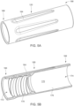
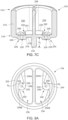
- the dispensing cap 124 of the anti-clogging spray tip preferably includes a tubular shaped body 212 having a proximal end 214 and distal end 216.
- the distal end 216 of the dispensing cap 124 preferably has a distal end wall 218 having an outer surface 219.
- the dispensing cap 124 preferably includes a first raised orifice 220 having a first raised mound 222 and a first spray opening 224 formed in the first raised mound 222.
- the dispensing cap 124 preferably includes a second raised orifice 226 having a second raised mound 228 and a second spray opening 230 formed in the second raised mound 228.
- the first and second raised orifices 220, 226 preferably project distally from the outer surface 219 of the distal end wall 218.
- the first fluid of the multiple component material is discharged through the first radial openings 200A, 200B of the first terminal chamber 194 ( FIG. 6F ), whereupon the first fluid is further directed through the first raised orifice 220 of the dispensing cap 124.
- the second fluid of the multiple component material that flows out of the radial openings 202A, 202B of the second terminal chamber 96 ( FIG. 6F ) is further directed through the second raised orifice 226 of the dispensing cap 124.
- the dispensing cap 124 desirably includes an external dividing wall 232 that projects distally from the outer surface 219 of the distal end wall 218 of the dispensing cap.
- the external dividing wall 232 has a height H 1 that projects beyond the outer surface 219 of the distal end wall 218 of the dispensing cap 124.
- the external dividing wall 232 functions as a barrier between the first and second raised orifices 220, 226 to prevent the first and second fluids that are sprayed from the respective first and second raised orifices from contacting one another and reacting together over the outer surface 219 of the distal end wall 218 of the end cap.
- the external dividing wall 232 serves to minimize clogging of one or more of the first and second spray openings 224, 230 of the respective first and second raised orifices 220, 226.
- the proximal end 214 of the tubular body 212 of the dispensing cap 124 preferably includes a first D-shaped chamber 234 that is configured to receive the first terminal chamber 194 located at the distal end 184 of the inner manifold 122 ( FIG. 6D ).
- the dispensing cap 124 desirably includes a second D-shaped chamber 236 that is configured to receive the second terminal chamber 196 located at the distal end 184 of the inner manifold 122.
- the dispensing cap 124 desirably includes an interior dividing wall 238 that separates the first D-shaped chamber 234 of the inner manifold 122 from the second D-shaped chamber 236 of the inner manifold 122.
- the interior dividing wall 238 accessible at the proximal end 214 of the tubular member 212 is preferably inserted into the space 198 extending between the first and second terminal chambers 194, 196 of the inner manifold 122 ( FIG. 6B ) for securing the dispensing cap 124 to the distal end of the inner manifold 122 ( FIG. 2 ).
- the dispensing cap 124 preferably includes the tubular body 212 having a proximal end 214 and a distal end 216.
- the dispensing cap 124 preferably includes the first raised orifice 220 having a first raised mound 222 and a first spray opening 224 formed in the first raised mound 222, which is in fluid communication with the first D-shaped chamber 234 of the dispensing cap.
- the dispensing cap 124 desirably includes a second raised orifice 226 having a second raised mound 228 with a second spray opening 230 formed in the second raised mound 228, which is in fluid communication with the second D-shaped chamber 236 of the dispensing cap.
- the interior dividing wall 238 divides the first D-shaped chamber 234 from the second D-shaped chamber 236 for insuring that the first and second fluids of the multiple component material remain separated from one another until they are discharged via the first and second spray openings 224, 230 of the respective first and second raised orifices 220, 226.
- the exterior dividing wall 232 of the dispensing cap 124 preferably projects distally from the outer surface 219 of the distal end wall 218 of the dispensing cap 124.
- the exterior dividing wall 232 divides the first and second raised orifices 220, 226 from one another.
- the exterior dividing wall 232 preferably defines a height H 1 that extends above and/or beyond the outer surface 219 of the distal end wall 218 of the dispensing cap 124.
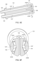
- the first D-shaped chamber 234 includes a first inner surface 239 of the distal end wall 218 having a first fluid pathway 240 formed therein that is in fluid communication with the first spray opening 224 of the first raised orifice 220.
- the first fluid of the multiple component material that is directed into the first D-shaped chamber 234 is advanced into the first fluid pathway 240 for being rapidly rotated within the first swirl chamber 248 prior to being dispensed from the first spray opening 224 of the first raised orifice 220 of the dispensing cap 124.
- the second D-shaped chamber 236 includes a second inner surface 241 of the distal end wall having a second fluid pathway 242 formed therein that is in fluid communication with the second spray opening 230 of the second raised orifice 226.
- the second fluid of the multiple component material that is directed into the second D-shaped chamber 236 is advanced into the second fluid pathway 242 for being rapidly rotated within the second swirl chamber 256 prior to being dispensed from the second spray opening 230 of the second raised orifice 226 of the dispensing cap 124.
- the dispensing cap 124 preferably includes the interior dividing wall 238 that divides the first D-shaped chamber 234 and the second D-shaped chamber 236 from one another.
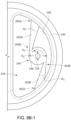
- the first D-shaped chamber 234 preferably includes an outer peripheral wall 244 having an inner surface 246 that is spaced away from the interior dividing wall 238.
- the first fluid pathway 240 preferably includes the first swirl chamber 248 that surrounds the first spray opening 224 and a pair of first flutes 250A, 250B that extend inwardly from the inner surface 246 of the peripheral wall 244 toward the first swirl chamber 248.
- the first flutes 250A, 250B may have respective widths that narrow between the inner surface 246 and the first swirl chamber 248 for increasing the speed of the first fluid as it passes through the first flutes 250A, 250B toward the first swirl chamber 248.
- the configuration of the first flutes 250A, 250B relative to the first swirl chamber 248 preferably rotates the first fluid in a counterclockwise direction designated R1 as it enters into the first swirl chamber 248.
- the first fluid is rotated in the counterclockwise direction R1 prior to being dispensed/sprayed through the first spray opening 224.
- the second D-shaped chamber 236 preferably includes an outer peripheral wall 252 having an inner surface 254 that is spaced away from the interior dividing wall 238.
- the second fluid pathway 242 preferably includes the second swirl chamber 256 that surrounds the second spray opening 224 and a pair of second flutes 258A, 258B that extend inwardly from the inner surface 254 of the peripheral wall 252 toward the second swirl chamber 256.
- the second flutes 258A, 258B may have widths that narrow between the inner surface 254 of the peripheral wall 252 and the second swirl chamber 256 for increasing the speed of the first fluid as it passes through the second flutes 258A, 258B toward the second swirl chamber 252.
- the configuration of the second flutes 258A, 258B relative to the second swirl chamber 256 preferably rotates the second fluid in a clockwise direction designated R2 as it enters into the second swirl chamber 252.
- the second fluid is rotated in the clockwise direction R2 prior to being dispensed through the second spray opening 230.
- the first fluid when the first fluid of the multiple component material enters into the first D-shaped chamber 234 of the dispensing cap 124, the first fluid preferably flows into the outer ends of the first flutes 250A, 250B, whereupon the first flutes direct the first fluid into the outer periphery of the first swirl chamber 248 for rotating the first fluid in the counterclockwise direction R1 as it is sprayed from the first spray opening 224.
- the first spray opening 224 of the first fluid pathway 240 preferably defines a first diameter D 1 and the first swirl chamber 248 preferably defines a second diameter D 2 that is greater than the first diameter D 1 of the first spray opening 224.
- the first spray opening 224 may be located in the center of the first swirl chamber 248.
- a first one 250A of the first flutes desirably has an outer end 260A that is located adjacent the inner surface 246 of the outer peripheral wall 244 and an inner end 260B that is located adjacent the outer periphery of the first swirl chamber 248.
- the first one 250A of the first flutes preferably has a width W 1 of about 0.127-0.254mm (0.005-0.010 inches) that narrows between the outer end 260A and the inner end 260B thereof.
- the narrowing of the first one 250A of the first flutes preferably increases the speed of the first fluid as it passes from the outer end 260A toward the inner end 260B of the first one 250A of the first flutes.
- a second one 250B of the first flutes desirably has an outer end 262A that is located adjacent the inner surface 246 of the outer peripheral wall 244 and an inner end 262B that is located adjacent the outer periphery of the first swirl chamber 248.
- the first one 250B of the first flutes preferably has a width W 2 that narrows between the outer end 262A and the inner end 262B thereof.
- the narrowing of the second one 250B of the first flutes preferably increases the speed of the first fluid as it passes from the outer end 262A toward the inner end 262B of the second one 250B of the first flutes.
- the first fluid pathway 240 is formed in the inner surface 239 of the distal end wall 218 of the first D-shaped chamber 234 of the dispensing cap 124.
- the first fluid pathway 240 including the first swirl chamber 248 and the first flutes 250A, 250B ( FIG. 8B-1 ) define a height H1 of about 0.127-0.254mm (0.005-0.010 inches).
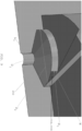
- the first spray opening 224 preferably has a diameter D1 that is less than the diameter D2 of the first swirl chamber 248. In one embodiment, the first spray opening preferably has a length L1.
- the dimensions of the first fluid pathway 240 may be modified to control the speed and/or the rate of rotation of the first fluid flowing through the first fluid pathway 240.
- one or more of the width and the height of the first flutes 250A, 250B may be modified to control the speed of the first fluid flowing through the first flutes.
- the degree of narrowing of the first flutes 250A. 250B between the respective outer and inner ends thereof may be modified to control the speed of the first fluid flowing through the first flutes.
- the diameter D1, the height H1, and/or the chamfer of the first swirl chamber 248 may be modified to control the speed and/or the rate of rotation of the first fluid that is directed into the first spray opening 224.
- the diameter D1 and the length L1 of the first spray opening 224 may be modified to control the speed and/or the dispensing angle of the first fluid as it is dispensed from the first spray opening.
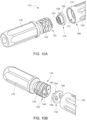
- the anti-clogging spray tip 114 may be assembled together by overmolding the gasket 118 onto the proximal end of the inner manifold 122.
- the distal end of the gasket 118/inner manifold 122 subassembly may be inserted into the first opening 172 at the proximal end 166 of the tip housing 120 for assembling the gasket 116/inner manifold 122/tip housing 120 subassembly.
- the external threads 142 at the distal end 130 of the connector 116 are preferably threaded into the internal threads 178 located inside the proximal end of the tip housing 120 for securing the connector 116 with the tip housing 120.
- the first and second D-shaped attachment plugs 154, 156 of the gasket 118 are desirably inserted into the respective D-shaped exit chambers 144, 146 at the distal end 130 of the connector 114.
- the outer surfaces of the D-shaped attachment plugs 154, 156 preferably form a friction fit with the inner surfaces of the respective D-shaped exit chambers 144, 146.
- the inner manifold 122 may be assembled with the tip housing 120 by inserting the first and second butterfly-shaped connectors 190, 192 and the annular sealing flange 186 located at the proximal end 182 of the inner manifold 122 into the second opening 174 at the distal end 168 of the tip housing 120.
- the inner manifold 122 is advanced in a proximal direction designated DIR1 until the first and second butterfly-shaped connectors 190, 192 are inserted into the respective butterfly-shaped openings 161, 163 formed in the distal end face 152 of the gasket 118 ( FIG. 4B ).
- the outer surfaces of the first and second butterfly-shaped connectors 190, 192 preferably form a friction fit with the respective butterfly-shaped openings 161, 163 ( FIG. 4B ) of the gasket 118 for securing the proximal end of the inner manifold 122 with the connector 116/gasket 118/tip housing 120 subassembly ( FIG. 10B ).
- the dispensing cap 124 is preferably assembled with the distal end 184 of the inner manifold 122 by juxtaposing and/or aligning the interior dividing wall 238 of the dispensing cap 124 with the space 198 that extends between opposing inner walls of the first and second terminal chambers 194, 196 of the inner manifold 122.
- the first and second D-shaped chambers 234, 236 accessible on the proximal side of the dispensing cap 124 are juxtaposed with the respective first and second terminal chambers 194, 196 located at the distal end 184 of the inner manifold 122.
- the dispensing cap 124 is advanced in the proximal direction DIR1 so that the interior dividing wall 238 of the dispensing cap 124 advances into the space 198 between the first and second terminal chambers 194, 196 of the inner manifold 122.
- the dispensing cap 124 is preferably advanced proximally until the end walls 239, 241 of the respective D-shaped chambers 234, 236 of the dispensing cap ( FIG. 8A ) abut against a distal face 205 ( FIG. 11B ) of the inner manifold 122.
- the first radial openings 200A, 200B ( FIG. 6F ) of the first terminal chamber 194 are preferably aligned with the outer ends of the first flutes 250A, 250B ( FIG. 8A ) of the dispensing cap 124
- the second radial openings 202A, 202B of the second terminal chamber 196 are preferably aligned with the outer ends of the second flutes 256A, 256B ( FIG. 8A ) of the dispensing cap 124.
- the first fluid of the multiple component material exits from the first terminal chamber via the first radial openings 200A, 200B ( FIG. 6F ) whereupon it is directed into the outer ends of the first flutes 250A, 250B ( FIG. 8A ).
- the second fluid of the multiple component material exits from the second terminal chamber via the second radial openings 202A, 202B ( FIG. 6F ) whereupon it is directed into the outer ends of the second flutes 254A, 254B ( FIG. 8A ).
- the fully assembled anti-clogging spray tip 114 preferably includes the connector 116, which has a distal end with external threads that mesh with internal threads located at the proximal end of the tip housing 120.
- the gasket 118 ( FIG. 2 ) is preferably disposed between the distal end of the connector 116 and the tip housing 120.
- the proximal end 166 of the tip housing 120 preferably surrounds the gasket.
- the anti-clogging spray tip 114 desirably includes the dispensing cap 124 that is accessible at the distal-most end of the anti-clogging spray tip 114.
- the inner manifold 122 FIG.
- the exterior dividing wall 232 of the dispensing cap 124 which projects distally from the distal end face 218 of the dispensing cap 124, provides a barrier that separates the first raised mound 220 from the second raised mound 226 so that the first and second fluids that are sprayed from the respective first and second raised mounds do not mix with one another over the distal end face 218, which minimizes the likelihood of the first and second raised mounds becoming clogged during a spraying operation.
- the anti-clogging spray tip 114 preferably includes the distal end 130 of the connector 116 inserted into the opening at the proximal end 166 of the tip housing 120.
- the external threads 142 ( FIG. 3A ) at the distal end 130 of the connector 116 are desirably threaded into the internal threads 178 located inside the proximal end 166 of the tip housing 120 for securing the connector 116 and the tip housing 120 to one another.
- the gasket 118 is desirably juxtaposed between the distal end 130 of the connector 116 and the annular sealing flange 186 of the inner manifold 122.
- the D-shaped attachment plugs 154, 156 of the gasket 118 which preferably project proximally from a proximal end face of the annular plate 148 of the gasket 118, are inserted into the respective D-shaped exit chambers 144, 146 ( FIG. 3C ) located at the distal end 130 of the connector 116 for securing the gasket 118 to the distal end of the connector.
- the annular plate 148 of the gasket 118 is preferably juxtaposed between the distal end 130 of the connector 116 and the annular sealing flange 186 located at the proximal end 182 of the inner manifold 122.
- the first and second butterfly-shaped connectors 190, 192, projecting proximally from the proximal end of the inner manifold 122, are preferably inserted into the butterfly shaped openings formed in the distal end face 152 ( FIG. 4B ) of the gasket 118 for assembling the proximal end of the inner manifold 122 with the gasket 118.
- the D-shaped attachment plugs 154, 156 of the gasket 118 are preferably inserted into the respective D-shaped exit chambers 144, 146 of the connector 116 ( FIG. 11B ), whereupon the outer surfaces of the D-shaped attachment plugs 154, 156 of the gasket 118 preferably form a friction fit with the inner surfaces of the respective D-shaped exit chambers 144, 146 of the connector 116.
- the first butterfly-shaped connector 190 of the inner manifold 122 FIG.
- the second butterfly-shaped connector 192 of the inner manifold 122 ( FIG. 2 ) preferably includes a second lumen 140" that is adapted to receive a second cannula that contains a second fluid of a multiple component material.
- the outer surfaces of the first and second butterfly-shaped connectors 190, 192 of the inner manifold are preferably inserted into the butterfly-shaped openings 161, 163 ( FIG. 4B ) formed in the distal face of the gasket 118, whereupon the outer surfaces of the first and second butterfly-shaped connectors 190, 192 form a friction fit with the respective butterfly-shaped openings of the gasket 118.
- the first butterfly-shaped connector 190 preferably includes a first lumen 138" that is adapted to receive a first cannula that contains a first fluid of a multiple component material.
- the second butterfly-shaped connector 192 preferably includes a second lumen 140" that is adapted to receive a second cannula that contains a second fluid of a multiple component material.
- the internal dividing wall 238 of the dispensing cap 124 is preferably inserted into the space 198 that divides the first and second terminal chambers 194, 196 of the inner manifold 122 from one another.
- the internal dividing wall 238 preferably forms a friction fit with the distal end 184 of the inner manifold 122 for securing the dispensing cap 124 and the inner manifold 122 together.
- the inner surfaces 239, 241 ( FIG. 7C ) of the distal end wall 218 of the respective first and second D-shaped chambers 234, 236 ( FIG. 7C ) of the dispensing cap preferably engage the distal end wall 205 ( FIG.
- the tubular member 212 of the dispensing cap 124 preferably surrounds the outer surfaces of the respective first and second terminal chambers 194, 196 of the inner manifold 122.
- the exterior dividing wall 232 of the dispensing cap 124 preferably projects distally from the distal face 219 of the distal end wall 218 of the dispensing cap 124 for acting as a barrier that separates the respective first and second raised orifices 220, 226 from one another.
- the first terminal chamber 194 of the inner manifold 122 preferably includes first radial openings 200A, 200B ( FIG. 6F ) that directs the first fluid of the multi-component material out of the first terminal chamber 194 and into the first fluid pathway 240 of the dispensing cap 124 ( FIG. 8A ) whereupon the first fluid is swirled within the first fluid pathway prior to being sprayed from the first spray opening 224 of the first raised orifice 220 of the dispensing cap 124.
- the second terminal chamber 196 of the inner manifold 122 preferably includes second radial openings 202A, 202B ( FIG.
- the external dividing wall 232 of the dispensing cap 124 projects distally from the distal surface 219 of the distal end wall 218 of the dispensing cap 124 to insure that the first and second fluids of the multi-component material do not mix on the distal surface 219 of the distal end wall 218, which may result in clogging of the first spray opening 224 of the first raised orifice 220 and/or the second spray opening 230 of the second raised orifice 226.
- a dispensing device 300 preferably includes a manifold 315 that directs the first and second fluids of a multi-component material through first and second cannulas 317, 319, respectively, toward an anti-clogging spray tip 324 that is constructed as disclosed herein.
- the anti-clogging spray tip 324 has a distally extending exterior dividing wall 332 that preferably divides and separates first and second raised mounds 320, 326 from one another.
- the first and second fluids may be sprayed from the respective first and second raised orifices 320, 326 whereupon the first and second fluids mix together for reacting with one another.
- a dispensing device 400 may be similar to that shown and described herein and preferably includes first and second one way check valves 425, 435 associated with each of the first and second fluids of a multiple component material to prevent back flow of the first and second fluids, which could result in clogging of the anti-clogging spray tip 424.
- the spray tips disclosed herein preferably include first and second fluid paths, which are adapted to receive the components (e.g., a first fluid and a second fluid) of a tissue sealant and/or other biological adhesive materials.
- the tissue sealants and/or other biologic adhesive materials are preferably used for closing incisions at surgical sites.
- the tissue sealants may include fibrin, which is comprised of thrombin, and a fibrinogen material, although other tissue sealing and tissue adhesive formulations may also be used.
Landscapes
- Health & Medical Sciences (AREA)
- Life Sciences & Earth Sciences (AREA)
- Surgery (AREA)
- Animal Behavior & Ethology (AREA)
- Heart & Thoracic Surgery (AREA)
- Biomedical Technology (AREA)
- Engineering & Computer Science (AREA)
- General Health & Medical Sciences (AREA)
- Public Health (AREA)
- Veterinary Medicine (AREA)
- Medical Informatics (AREA)
- Molecular Biology (AREA)
- Nuclear Medicine, Radiotherapy & Molecular Imaging (AREA)
- Anesthesiology (AREA)
- Vascular Medicine (AREA)
- Hematology (AREA)
- Infusion, Injection, And Reservoir Apparatuses (AREA)
- Surgical Instruments (AREA)
- Nozzles (AREA)
Claims (15)
- Sprühspitze (114) zum Ausgeben von Flüssigkeiten, die miteinander reagieren, umfassend:ein erstes Lumen (138);ein zweites Lumen (140);eine Abgabekappe (124), die an den distalen Enden des jeweiligen ersten und zweiten Lumens (138, 140) angeordnet ist und ein distales Ende der Sprühspitze (114) definiert, wobei die Abgabekappe (124) umfassteine distale Endwand (218), die ein geschlossenes Ende der Abgabekappe (124) definiert;eine erste Sprühöffnung (220), die in der distalen Endwand (218) ausgebildet ist und in Flüssigkeitsverbindung mit dem ersten Lumen (138) steht, wobei die erste Sprühöffnung (220) einen ersten erhabenen Hügel (222) einschließt, der distal von einer Außenoberfläche der distalen Endwand (218) der Abgabekappe (124) hervorsteht,eine zweite Sprühöffnung (226), die in der distalen Endwand (218) ausgebildet ist und in Flüssigkeitsverbindung mit dem zweiten Lumen (140) steht, wobei die zweite Sprühöffnung (226) einen zweiten erhabenen Hügel (228) einschließt, der distal von der Außenoberfläche der distalen Endwand (218) der Abgabekappe (124) hervorsteht, undeine äußere Trennwand (232), die distal von der distalen Endwand (218) der Abgabekappe (124) hervorsteht und sich zwischen der ersten und der zweiten Sprühöffnung (220, 226) zum Bilden einer Barriere zwischen der ersten und der zweiten Sprühöffnung (220, 226) erstreckt.
- Sprühspitze nach Anspruch 1, ferner umfassend einen zylindrisch geformten Körper (212) mit einem proximalen Ende (214), das zur Aufnahme der distalen Enden des ersten und des zweiten Lumens offen ist, und einem distalen Ende, das durch die distale Endwand verschlossen ist.
- Sprühspitze nach Anspruch 1, wobei die äußere Trennwand ein proximales Ende aufweist, das an der Außenoberfläche der distalen Endwand befestigt ist, und ein distales, freies Ende, das distal zu den jeweiligen Scheitelpunkten des ersten und des zweiten erhabenen Hügels liegt, um ein distalstes Ende der Abgabekappe zu definieren.
- Sprühspitze nach Anspruch 3, wobei der erste und der zweite erhabene Hügel der jeweiligen ersten und zweiten Sprühöffnungen hydrophobe Oberflächen umfassen, die zum Abweisen von Flüssigkeiten geeignet sind.
- Sprühspitze nach Anspruch 2, wobei die Abgabekappe ferner umfasst:
eine innere Trennwand (238), die sich innerhalb des zylindrisch geformten Körpers befindet und sich zwischen dem proximalen Ende des zylindrisch geformten Körpers und der distalen Endwand erstreckt, um einen Innenbereich der Abgabekappe in eine erste Kammer (234), die in Flüssigkeitsverbindung mit dem ersten Lumen steht, und eine zweite Kammer (236), die in Flüssigkeitsverbindung mit dem zweiten Lumen steht, zu unterteilen. - Sprühspitze nach Anspruch 5, wobei die distale Endwand der Abgabekappe eine Innenoberfläche (239) aufweist, und wobei die innere Trennwand ein distales Ende aufweist, das an der Innenoberfläche der distalen Endwand befestigt ist, um die Innenoberfläche der distalen Endwand der Abgabekappe in einen ersten Bereich, der innerhalb der ersten Kammer angeordnet ist, und einen zweiten Bereich, der innerhalb der zweiten Kammer angeordnet ist, zu unterteilen.
- Sprühspitze nach Anspruch 6, ferner umfassend:einen ersten Flüssigkeitsweg (240), der im ersten Bereich der Innenoberfläche der distalen Endwand der Abgabekappe ausgebildet ist, wobei der erste Flüssigkeitsweg in Flüssigkeitsverbindung mit der ersten Sprühöffnung steht;einen zweiten Flüssigkeitsweg (242), der im zweiten Bereich der Innenoberfläche der distalen Endwand der Abgabekappe ausgebildet ist, wobei der zweite Flüssigkeitsweg in Flüssigkeitsverbindung mit der zweiten Sprühöffnung steht.
- Sprühspitze nach Anspruch 7, wobei der erste Flüssigkeitsweg umfasst:eine erste Wirbelkammer (248), die in Flüssigkeitsverbindung mit der ersten Sprühöffnung steht;ein Paar erster Nuten (250A, 250B), die sich von der ersten Wirbelkammer radial nach außen erstrecken.
- Sprühspitze nach Anspruch 8, wobei der zweite Flüssigkeitsweg umfasst:eine zweite Wirbelkammer (256), die in Flüssigkeitsverbindung mit der zweiten Sprühöffnung steht;ein Paar zweiter Nuten (258A, 258B), die sich von der zweiten Wirbelkammer radial nach außen erstrecken.
- Sprühspitze nach Anspruch 9, ferner umfassend:wobei das erste Lumen eine erste Flüssigkeit enthält, die so konfiguriert ist, dass sie in den ersten Flüssigkeitsweg der Abgabekappe geleitet wird, wobei die erste Wirbelkammer so konfiguriert ist, dass sie die erste Flüssigkeit rotieren lässt, bevor die erste Flüssigkeit aus der ersten Sprühöffnung abgegeben wird;wobei das zweite Lumen eine zweite Flüssigkeit enthält, die so konfiguriert ist, dass sie in den zweiten Flüssigkeitsweg der Abgabekappe geleitet wird, wobei die zweite Wirbelkammer so konfiguriert ist, dass sie die zweite Flüssigkeit rotieren lässt, bevor die zweite Flüssigkeit aus der ersten Sprühöffnung abgegeben wird, wobei die erste und die zweite Flüssigkeit chemisch miteinander reagieren, nachdem sie aus der jeweiligen ersten und zweiten Sprühöffnung abgegeben wurden.
- Sprühspitze nach Anspruch 10, ferner umfassend:eine erste Spritze, die die erste Flüssigkeit enthält;eine zweite Spritze, die die zweite Flüssigkeit enthält;ein erstes Einweg-Rückschlagventil (425), das sich stromabwärts der ersten Spritze befindet und in Flüssigkeitsverbindung mit dem ersten Lumen steht;ein zweites Einweg-Rückschlagventil (435), das stromabwärts der zweiten Spritze angeordnet ist und in Flüssigkeitsverbindung mit dem zweiten Lumen steht.
- Sprühspitze nach Anspruch 9, wobei die ersten Nuten auf gegenüberliegenden Seiten der ersten Wirbelkammer voneinander weg verlaufen, und wobei die zweiten Nuten auf gegenüberliegenden Seiten der zweiten Wirbelkammer voneinander weg verlaufen.
- Sprühspitze nach Anspruch 7, wobei der erste Flüssigkeitsweg umfasst:eine erste Wirbelkammer (248), die in der Innenoberfläche der distalen Endwand gebildet ist und die in Flüssigkeitsverbindung mit der ersten Sprühöffnung steht;ein Paar erster Nuten (250A, 250B), die in der Innenoberfläche der distalen Endwand ausgebildet sind und sich von der ersten Wirbelkammer radial nach außen zu einem Außenumfang der Innenoberfläche der distalen Endwand der Abgabekappe erstrecken, wobei jede der ersten Nuten eine Breite aufweist.
- Sprühspitze nach Anspruch 13, wobei der zweite Flüssigkeitsweg umfasst:eine zweite Wirbelkammer (256), die in der Innenoberfläche der distalen Endwand gebildet ist und die in Flüssigkeitsverbindung mit der zweiten Sprühöffnung steht;ein Paar zweiter Nuten (258A, 258B), die in der Innenoberfläche der distalen Endwand ausgebildet sind und sich von der zweiten Wirbelkammer radial nach außen zu einem Außenumfang der Innenoberfläche der distalen Endwand der Abgabekappe erstrecken, wobei jede der zweiten Nuten eine Breite aufweist.
- Sprühspitze nach Anspruch 2, wobei die distale Endwand eine Innen- und eine Außenoberfläche aufweist und die Trennwand sich über die Außenoberfläche der distalen Endwand der Abgabekappe und zwischen der ersten und der zweiten Sprühöffnung erstreckt, um die Barriere zwischen der ersten und der zweiten Sprühöffnung zu bilden.
Applications Claiming Priority (2)
| Application Number | Priority Date | Filing Date | Title |
|---|---|---|---|
| US16/593,783 US12207810B2 (en) | 2019-10-04 | 2019-10-04 | Dispensing systems and devices having anti-clogging spray tips for dispensing two or more fluids that react together |
| PCT/IB2020/059226 WO2021064643A1 (en) | 2019-10-04 | 2020-10-01 | Dispensing systems and devices having anti-clogging spray tips for dispensing two or more fluids that react together |
Publications (3)
| Publication Number | Publication Date |
|---|---|
| EP4037576A1 EP4037576A1 (de) | 2022-08-10 |
| EP4037576C0 EP4037576C0 (de) | 2025-03-05 |
| EP4037576B1 true EP4037576B1 (de) | 2025-03-05 |
Family
ID=72840592
Family Applications (1)
| Application Number | Title | Priority Date | Filing Date |
|---|---|---|---|
| EP20790067.1A Active EP4037576B1 (de) | 2019-10-04 | 2020-10-01 | Ausgabesysteme und vorrichtungen mit verstopfungsverhindernden sprühspitzen zur abgabe von zwei oder mehr flüssigkeiten, die miteinander reagieren |
Country Status (9)
| Country | Link |
|---|---|
| US (1) | US12207810B2 (de) |
| EP (1) | EP4037576B1 (de) |
| JP (1) | JP7528201B2 (de) |
| KR (1) | KR20220113926A (de) |
| CN (1) | CN114513992B (de) |
| AU (1) | AU2020358460A1 (de) |
| CA (1) | CA3156712A1 (de) |
| IL (1) | IL291899B2 (de) |
| WO (1) | WO2021064643A1 (de) |
Families Citing this family (1)
| Publication number | Priority date | Publication date | Assignee | Title |
|---|---|---|---|---|
| EP4294281A1 (de) | 2021-02-19 | 2023-12-27 | Ethicon, Inc. | Systeme und vorrichtungen zur abgabe von biokompatiblen reaktiven formulierungen und steuerung der vernetzung der reaktiven komponenten der biokompatiblen reaktiven formulierungen |
Family Cites Families (35)
| Publication number | Priority date | Publication date | Assignee | Title |
|---|---|---|---|---|
| US2158848A (en) * | 1936-03-25 | 1939-05-16 | Monowatt Electric Corp | Electric socket |
| EP0294672B1 (de) * | 1987-06-10 | 1992-08-12 | Wilhelm A. Keller | Doppel-Austragkartusche für Zweikomponentenmassen |
| DE3725552A1 (de) | 1987-08-01 | 1989-02-09 | Hoechst Ag | Spruehkopf zum applizieren eines mehrkomponentenmaterials mittels gas |
| CA2039086A1 (en) | 1991-03-26 | 1992-09-27 | Thomas Barty | Spray gun nozzle head |
| US5368563A (en) | 1991-12-18 | 1994-11-29 | Micromedics, Inc. | Sprayer assembly for physiologic glue |
| US5526981A (en) | 1994-10-31 | 1996-06-18 | Sanson; Bruce A. | Adhesive spray system, and methods of constructing and utilizing same |
| US6835186B1 (en) * | 1995-01-16 | 2004-12-28 | Baxter International, Inc. | Mechanical breakup unit for biochemically reactive fluid delivery device |
| US5759169A (en) | 1996-03-13 | 1998-06-02 | New York Blood Center Inc. | Fibrin sealant glue-gun |
| AU4755802A (en) * | 1998-03-06 | 2002-08-01 | Baxter International Inc. | Turbulence mixing head for a tissue sealant applicator and spray head for same |
| US6471670B1 (en) * | 1998-10-05 | 2002-10-29 | Karl Enrenfels | Fibrin sealant applicator system |
| US6432084B1 (en) | 1999-05-07 | 2002-08-13 | Baxter International Inc. | Non-newtonian fluid spray applicator and method |
| JP3933880B2 (ja) | 2001-03-27 | 2007-06-20 | 住友ベークライト株式会社 | 生体組織接着剤塗布用具 |
| US6921381B2 (en) | 2001-10-05 | 2005-07-26 | Baxter International Inc. | Laparoscopic spray device and method of use |
| US6547161B1 (en) | 2001-12-18 | 2003-04-15 | Tiao-Hsiang Huang | Spray paint gun head |
| US6612506B1 (en) | 2002-10-09 | 2003-09-02 | Tiao-Hsiang Huang | Spray gun head with dual air ports & a diverter bushing |
| JP4394075B2 (ja) | 2003-12-22 | 2010-01-06 | ニロ・アクティーゼルスカブ | 気体により液体を霧化するノズル及び霧化方法 |
| TWM275032U (en) | 2004-07-23 | 2005-09-11 | Chia Chung Prec Ind Co Ltd | Head structure of jetting gun |
| US7611494B2 (en) * | 2005-02-08 | 2009-11-03 | Confluent Surgical, Inc. | Spray for fluent materials |
| US7635343B2 (en) | 2005-04-21 | 2009-12-22 | Arteriocyte Medical Systems, Inc. | Fluid dispenser |
| US8940382B2 (en) | 2006-02-13 | 2015-01-27 | Harco Americas, Inc. | Waterproof coating system and method of application |
| JP2007090347A (ja) | 2006-12-25 | 2007-04-12 | Nipro Corp | 生体接着剤投与用スプレーヘッド |
| EP1955660A3 (de) * | 2007-02-09 | 2010-05-12 | Terumo Kabushiki Kaisha | Sprühvorrichtung |
| US20100198255A1 (en) | 2007-06-15 | 2010-08-05 | Juridical Fdn The Chemo-Sero-Therapeutic Res. Ins. | Spray head, and apparatus and method for applying biological tissue adhesive |
| US8684282B2 (en) | 2007-10-25 | 2014-04-01 | Plantation Key Design Inc. | Adjustable spray pattern atomizer |
| US8408480B2 (en) | 2008-04-25 | 2013-04-02 | Confluent Surgical, Inc. | Self-cleaning spray tip |
| US8033483B2 (en) | 2008-04-25 | 2011-10-11 | Confluent Surgical Inc. | Silicone spray tip |
| US8210453B2 (en) | 2008-09-12 | 2012-07-03 | Confluent Surgical, Inc. | Spray applicator |
| CH699808A1 (de) * | 2008-10-30 | 2010-04-30 | Medmix Systems Ag | Sprühkopf und Sprühvorrichtung mit einem solchen Sprühkopf. |
| US10987093B2 (en) * | 2010-04-05 | 2021-04-27 | Neomend, Inc. | Method and apparatus for wound sealant application |
| US8672237B2 (en) * | 2010-06-25 | 2014-03-18 | Baxter International Inc. | Device for mixing and dispensing of two-component reactive surgical sealant |
| US20130325059A1 (en) | 2012-06-01 | 2013-12-05 | Devicegenerics, Inc. | Non-Clogging Airless Spray for High Viscosity, High Surface Tension Fluids |
| AU2014405591B2 (en) | 2014-09-04 | 2020-05-21 | Ethicon, Inc. | Minimally clogging device for delivery of fluids and method of use |
| CN109414712B (zh) * | 2016-05-03 | 2022-06-17 | Dlh鲍尔斯公司 | 喷嘴组件、组装方法及两部分式流体喷嘴组件 |
| US10737058B2 (en) | 2016-12-28 | 2020-08-11 | Ethicon Llc | Rigid and flexible laparoscopic multiple component material dispensing devices and methods |
| CN113365737A (zh) * | 2018-11-02 | 2021-09-07 | Dlh鲍尔斯公司 | 用于喷射粘性牛顿流体的气雾喷嘴组件和喷嘴杯构件 |
-
2019
- 2019-10-04 US US16/593,783 patent/US12207810B2/en active Active
-
2020
- 2020-10-01 AU AU2020358460A patent/AU2020358460A1/en not_active Abandoned
- 2020-10-01 JP JP2022520466A patent/JP7528201B2/ja active Active
- 2020-10-01 EP EP20790067.1A patent/EP4037576B1/de active Active
- 2020-10-01 CN CN202080069497.6A patent/CN114513992B/zh active Active
- 2020-10-01 CA CA3156712A patent/CA3156712A1/en active Pending
- 2020-10-01 IL IL291899A patent/IL291899B2/en unknown
- 2020-10-01 WO PCT/IB2020/059226 patent/WO2021064643A1/en not_active Ceased
- 2020-10-14 KR KR1020227014830A patent/KR20220113926A/ko not_active Withdrawn
Also Published As
| Publication number | Publication date |
|---|---|
| WO2021064643A1 (en) | 2021-04-08 |
| CA3156712A1 (en) | 2021-04-08 |
| AU2020358460A1 (en) | 2022-04-07 |
| JP2022550854A (ja) | 2022-12-05 |
| CN114513992A (zh) | 2022-05-17 |
| JP7528201B2 (ja) | 2024-08-05 |
| IL291899B1 (en) | 2025-12-01 |
| KR20220113926A (ko) | 2022-08-17 |
| CN114513992B (zh) | 2025-10-17 |
| EP4037576A1 (de) | 2022-08-10 |
| US12207810B2 (en) | 2025-01-28 |
| EP4037576C0 (de) | 2025-03-05 |
| IL291899B2 (en) | 2026-04-01 |
| US20210100543A1 (en) | 2021-04-08 |
| IL291899A (en) | 2022-06-01 |
Similar Documents
| Publication | Publication Date | Title |
|---|---|---|
| US11872584B2 (en) | Spray devices including side-by-side spray tips having fluid pathways with swirl chambers for dispensing two fluids that chemically react together | |
| US9381005B2 (en) | Spray head for two component mixer | |
| AU2002363414B2 (en) | Laparoscopic spray device and method of use | |
| US12114843B2 (en) | Sealant applicators having mixing and spraying assemblies with malleable sections and spray tips having reduced dimensions | |
| CN109640834B (zh) | 用于同时多向递送不同流体的喷射顶端 | |
| US12207810B2 (en) | Dispensing systems and devices having anti-clogging spray tips for dispensing two or more fluids that react together | |
| US20160051752A1 (en) | Applicator, mixing tip and method for dispensing a mixed fluid | |
| WO2017053107A1 (en) | Spray or drip tips having multiple outlet channels | |
| KR102385836B1 (ko) | 복강경 수술용 2약액 혼합 분사 장치 |
Legal Events
| Date | Code | Title | Description |
|---|---|---|---|
| STAA | Information on the status of an ep patent application or granted ep patent |
Free format text: STATUS: UNKNOWN |
|
| STAA | Information on the status of an ep patent application or granted ep patent |
Free format text: STATUS: THE INTERNATIONAL PUBLICATION HAS BEEN MADE |
|
| PUAI | Public reference made under article 153(3) epc to a published international application that has entered the european phase |
Free format text: ORIGINAL CODE: 0009012 |
|
| STAA | Information on the status of an ep patent application or granted ep patent |
Free format text: STATUS: REQUEST FOR EXAMINATION WAS MADE |
|
| 17P | Request for examination filed |
Effective date: 20220321 |
|
| AK | Designated contracting states |
Kind code of ref document: A1 Designated state(s): AL AT BE BG CH CY CZ DE DK EE ES FI FR GB GR HR HU IE IS IT LI LT LU LV MC MK MT NL NO PL PT RO RS SE SI SK SM TR |
|
| DAV | Request for validation of the european patent (deleted) | ||
| DAX | Request for extension of the european patent (deleted) | ||
| GRAP | Despatch of communication of intention to grant a patent |
Free format text: ORIGINAL CODE: EPIDOSNIGR1 |
|
| STAA | Information on the status of an ep patent application or granted ep patent |
Free format text: STATUS: GRANT OF PATENT IS INTENDED |
|
| RAP3 | Party data changed (applicant data changed or rights of an application transferred) |
Owner name: ETHICON, INC. |
|
| INTG | Intention to grant announced |
Effective date: 20241210 |
|
| GRAS | Grant fee paid |
Free format text: ORIGINAL CODE: EPIDOSNIGR3 |
|
| GRAA | (expected) grant |
Free format text: ORIGINAL CODE: 0009210 |
|
| STAA | Information on the status of an ep patent application or granted ep patent |
Free format text: STATUS: THE PATENT HAS BEEN GRANTED |
|
| AK | Designated contracting states |
Kind code of ref document: B1 Designated state(s): AL AT BE BG CH CY CZ DE DK EE ES FI FR GB GR HR HU IE IS IT LI LT LU LV MC MK MT NL NO PL PT RO RS SE SI SK SM TR |
|
| REG | Reference to a national code |
Ref country code: GB Ref legal event code: FG4D |
|
| REG | Reference to a national code |
Ref country code: CH Ref legal event code: EP |
|
| REG | Reference to a national code |
Ref country code: IE Ref legal event code: FG4D |
|
| REG | Reference to a national code |
Ref country code: DE Ref legal event code: R096 Ref document number: 602020047289 Country of ref document: DE |
|
| U01 | Request for unitary effect filed |
Effective date: 20250328 |
|
| U07 | Unitary effect registered |
Designated state(s): AT BE BG DE DK EE FI FR IT LT LU LV MT NL PT RO SE SI Effective date: 20250409 |
|
| PG25 | Lapsed in a contracting state [announced via postgrant information from national office to epo] |
Ref country code: RS Free format text: LAPSE BECAUSE OF FAILURE TO SUBMIT A TRANSLATION OF THE DESCRIPTION OR TO PAY THE FEE WITHIN THE PRESCRIBED TIME-LIMIT Effective date: 20250605 |
|
| PG25 | Lapsed in a contracting state [announced via postgrant information from national office to epo] |
Ref country code: ES Free format text: LAPSE BECAUSE OF FAILURE TO SUBMIT A TRANSLATION OF THE DESCRIPTION OR TO PAY THE FEE WITHIN THE PRESCRIBED TIME-LIMIT Effective date: 20250305 |
|
| PG25 | Lapsed in a contracting state [announced via postgrant information from national office to epo] |
Ref country code: NO Free format text: LAPSE BECAUSE OF FAILURE TO SUBMIT A TRANSLATION OF THE DESCRIPTION OR TO PAY THE FEE WITHIN THE PRESCRIBED TIME-LIMIT Effective date: 20250605 |
|
| PG25 | Lapsed in a contracting state [announced via postgrant information from national office to epo] |
Ref country code: HR Free format text: LAPSE BECAUSE OF FAILURE TO SUBMIT A TRANSLATION OF THE DESCRIPTION OR TO PAY THE FEE WITHIN THE PRESCRIBED TIME-LIMIT Effective date: 20250305 |
|
| PG25 | Lapsed in a contracting state [announced via postgrant information from national office to epo] |
Ref country code: GR Free format text: LAPSE BECAUSE OF FAILURE TO SUBMIT A TRANSLATION OF THE DESCRIPTION OR TO PAY THE FEE WITHIN THE PRESCRIBED TIME-LIMIT Effective date: 20250606 |
|
| PG25 | Lapsed in a contracting state [announced via postgrant information from national office to epo] |
Ref country code: SM Free format text: LAPSE BECAUSE OF FAILURE TO SUBMIT A TRANSLATION OF THE DESCRIPTION OR TO PAY THE FEE WITHIN THE PRESCRIBED TIME-LIMIT Effective date: 20250305 |
|
| PG25 | Lapsed in a contracting state [announced via postgrant information from national office to epo] |
Ref country code: PL Free format text: LAPSE BECAUSE OF FAILURE TO SUBMIT A TRANSLATION OF THE DESCRIPTION OR TO PAY THE FEE WITHIN THE PRESCRIBED TIME-LIMIT Effective date: 20250305 |
|
| U20 | Renewal fee for the european patent with unitary effect paid |
Year of fee payment: 6 Effective date: 20250909 |
|
| PG25 | Lapsed in a contracting state [announced via postgrant information from national office to epo] |
Ref country code: CZ Free format text: LAPSE BECAUSE OF FAILURE TO SUBMIT A TRANSLATION OF THE DESCRIPTION OR TO PAY THE FEE WITHIN THE PRESCRIBED TIME-LIMIT Effective date: 20250305 |
|
| PG25 | Lapsed in a contracting state [announced via postgrant information from national office to epo] |
Ref country code: SK Free format text: LAPSE BECAUSE OF FAILURE TO SUBMIT A TRANSLATION OF THE DESCRIPTION OR TO PAY THE FEE WITHIN THE PRESCRIBED TIME-LIMIT Effective date: 20250305 |
|
| PG25 | Lapsed in a contracting state [announced via postgrant information from national office to epo] |
Ref country code: IS Free format text: LAPSE BECAUSE OF FAILURE TO SUBMIT A TRANSLATION OF THE DESCRIPTION OR TO PAY THE FEE WITHIN THE PRESCRIBED TIME-LIMIT Effective date: 20250705 |
|
| PLBE | No opposition filed within time limit |
Free format text: ORIGINAL CODE: 0009261 |
|
| STAA | Information on the status of an ep patent application or granted ep patent |
Free format text: STATUS: NO OPPOSITION FILED WITHIN TIME LIMIT |
|
| REG | Reference to a national code |
Ref country code: CH Ref legal event code: L10 Free format text: ST27 STATUS EVENT CODE: U-0-0-L10-L00 (AS PROVIDED BY THE NATIONAL OFFICE) Effective date: 20260114 |
|
| 26N | No opposition filed |
Effective date: 20251208 |