EP4037458B1 - System and method for testing an agricultural implement - Google Patents
System and method for testing an agricultural implement Download PDFInfo
- Publication number
- EP4037458B1 EP4037458B1 EP20740404.7A EP20740404A EP4037458B1 EP 4037458 B1 EP4037458 B1 EP 4037458B1 EP 20740404 A EP20740404 A EP 20740404A EP 4037458 B1 EP4037458 B1 EP 4037458B1
- Authority
- EP
- European Patent Office
- Prior art keywords
- frame
- fluid
- flow
- valve
- outlet
- Prior art date
- Legal status (The legal status is an assumption and is not a legal conclusion. Google has not performed a legal analysis and makes no representation as to the accuracy of the status listed.)
- Active
Links
- 238000012360 testing method Methods 0.000 title claims description 23
- 238000000034 method Methods 0.000 title claims description 18
- 239000012530 fluid Substances 0.000 claims description 53
- 239000002699 waste material Substances 0.000 claims description 7
- 238000004891 communication Methods 0.000 claims description 6
- 238000005086 pumping Methods 0.000 claims description 5
- 230000000007 visual effect Effects 0.000 claims description 2
- 230000001419 dependent effect Effects 0.000 claims 1
- 239000003337 fertilizer Substances 0.000 description 9
- 239000000463 material Substances 0.000 description 8
- 239000007788 liquid Substances 0.000 description 6
- 239000002689 soil Substances 0.000 description 4
- XLYOFNOQVPJJNP-UHFFFAOYSA-N water Substances O XLYOFNOQVPJJNP-UHFFFAOYSA-N 0.000 description 3
- 238000010586 diagram Methods 0.000 description 2
- 230000002262 irrigation Effects 0.000 description 2
- 238000003973 irrigation Methods 0.000 description 2
- 230000007246 mechanism Effects 0.000 description 2
- 238000012544 monitoring process Methods 0.000 description 2
- 239000002245 particle Substances 0.000 description 2
- 238000007792 addition Methods 0.000 description 1
- 239000012773 agricultural material Substances 0.000 description 1
- 238000005056 compaction Methods 0.000 description 1
- 238000007796 conventional method Methods 0.000 description 1
- 238000012217 deletion Methods 0.000 description 1
- 230000037430 deletion Effects 0.000 description 1
- 238000004519 manufacturing process Methods 0.000 description 1
- 238000005259 measurement Methods 0.000 description 1
- 238000012986 modification Methods 0.000 description 1
- 230000004048 modification Effects 0.000 description 1
- 235000015097 nutrients Nutrition 0.000 description 1
- 238000009987 spinning Methods 0.000 description 1
- 238000010998 test method Methods 0.000 description 1
Images


Classifications
-
- F—MECHANICAL ENGINEERING; LIGHTING; HEATING; WEAPONS; BLASTING
- F04—POSITIVE - DISPLACEMENT MACHINES FOR LIQUIDS; PUMPS FOR LIQUIDS OR ELASTIC FLUIDS
- F04C—ROTARY-PISTON, OR OSCILLATING-PISTON, POSITIVE-DISPLACEMENT MACHINES FOR LIQUIDS; ROTARY-PISTON, OR OSCILLATING-PISTON, POSITIVE-DISPLACEMENT PUMPS
- F04C14/00—Control of, monitoring of, or safety arrangements for, machines, pumps or pumping installations
- F04C14/24—Control of, monitoring of, or safety arrangements for, machines, pumps or pumping installations characterised by using valves controlling pressure or flow rate, e.g. discharge valves or unloading valves
- F04C14/26—Control of, monitoring of, or safety arrangements for, machines, pumps or pumping installations characterised by using valves controlling pressure or flow rate, e.g. discharge valves or unloading valves using bypass channels
-
- A—HUMAN NECESSITIES
- A01—AGRICULTURE; FORESTRY; ANIMAL HUSBANDRY; HUNTING; TRAPPING; FISHING
- A01C—PLANTING; SOWING; FERTILISING
- A01C23/00—Distributing devices specially adapted for liquid manure or other fertilising liquid, including ammonia, e.g. transport tanks or sprinkling wagons
- A01C23/007—Metering or regulating systems
-
- A—HUMAN NECESSITIES
- A01—AGRICULTURE; FORESTRY; ANIMAL HUSBANDRY; HUNTING; TRAPPING; FISHING
- A01C—PLANTING; SOWING; FERTILISING
- A01C7/00—Sowing
- A01C7/08—Broadcast seeders; Seeders depositing seeds in rows
- A01C7/10—Devices for adjusting the seed-box ; Regulation of machines for depositing quantities at intervals
- A01C7/107—Calibration of the seed rate
-
- F—MECHANICAL ENGINEERING; LIGHTING; HEATING; WEAPONS; BLASTING
- F04—POSITIVE - DISPLACEMENT MACHINES FOR LIQUIDS; PUMPS FOR LIQUIDS OR ELASTIC FLUIDS
- F04B—POSITIVE-DISPLACEMENT MACHINES FOR LIQUIDS; PUMPS
- F04B49/00—Control, e.g. of pump delivery, or pump pressure of, or safety measures for, machines, pumps, or pumping installations, not otherwise provided for, or of interest apart from, groups F04B1/00 - F04B47/00
- F04B49/22—Control, e.g. of pump delivery, or pump pressure of, or safety measures for, machines, pumps, or pumping installations, not otherwise provided for, or of interest apart from, groups F04B1/00 - F04B47/00 by means of valves
- F04B49/24—Bypassing
-
- F—MECHANICAL ENGINEERING; LIGHTING; HEATING; WEAPONS; BLASTING
- F04—POSITIVE - DISPLACEMENT MACHINES FOR LIQUIDS; PUMPS FOR LIQUIDS OR ELASTIC FLUIDS
- F04B—POSITIVE-DISPLACEMENT MACHINES FOR LIQUIDS; PUMPS
- F04B51/00—Testing machines, pumps, or pumping installations
-
- A—HUMAN NECESSITIES
- A01—AGRICULTURE; FORESTRY; ANIMAL HUSBANDRY; HUNTING; TRAPPING; FISHING
- A01C—PLANTING; SOWING; FERTILISING
- A01C15/00—Fertiliser distributors
-
- A—HUMAN NECESSITIES
- A01—AGRICULTURE; FORESTRY; ANIMAL HUSBANDRY; HUNTING; TRAPPING; FISHING
- A01C—PLANTING; SOWING; FERTILISING
- A01C21/00—Methods of fertilising, sowing or planting
- A01C21/005—Following a specific plan, e.g. pattern
-
- F—MECHANICAL ENGINEERING; LIGHTING; HEATING; WEAPONS; BLASTING
- F04—POSITIVE - DISPLACEMENT MACHINES FOR LIQUIDS; PUMPS FOR LIQUIDS OR ELASTIC FLUIDS
- F04B—POSITIVE-DISPLACEMENT MACHINES FOR LIQUIDS; PUMPS
- F04B17/00—Pumps characterised by combination with, or adaptation to, specific driving engines or motors
- F04B17/03—Pumps characterised by combination with, or adaptation to, specific driving engines or motors driven by electric motors
-
- F—MECHANICAL ENGINEERING; LIGHTING; HEATING; WEAPONS; BLASTING
- F04—POSITIVE - DISPLACEMENT MACHINES FOR LIQUIDS; PUMPS FOR LIQUIDS OR ELASTIC FLUIDS
- F04B—POSITIVE-DISPLACEMENT MACHINES FOR LIQUIDS; PUMPS
- F04B23/00—Pumping installations or systems
- F04B23/02—Pumping installations or systems having reservoirs
-
- F—MECHANICAL ENGINEERING; LIGHTING; HEATING; WEAPONS; BLASTING
- F04—POSITIVE - DISPLACEMENT MACHINES FOR LIQUIDS; PUMPS FOR LIQUIDS OR ELASTIC FLUIDS
- F04C—ROTARY-PISTON, OR OSCILLATING-PISTON, POSITIVE-DISPLACEMENT MACHINES FOR LIQUIDS; ROTARY-PISTON, OR OSCILLATING-PISTON, POSITIVE-DISPLACEMENT PUMPS
- F04C14/00—Control of, monitoring of, or safety arrangements for, machines, pumps or pumping installations
- F04C14/28—Safety arrangements; Monitoring
Definitions
- Embodiments of the present disclosure relate generally to test systems and methods for validating and calibrating agricultural equipment, such as planters, fertilizer applicators, etc.
- Crop yields are affected by a variety of factors, such as seed placement, soil quality, weather, irrigation, and nutrient applications. Seeds are typically planted in trenches formed by discs or other mechanisms of a planter row unit.
- Adding materials (such as fertilizers) adjacent to seed trenches during planting is a good way to deliver the materials to the soil for growing plants to access the material during a later growing stage. This eliminates a pass over the field to reduce compaction of the soil from separate planting and material application passes.
- Some of the fertilizer is placed adjacent to the seed trench, and when the plant grows and extends into the zone where the fertilizer was placed, the plant can then use the fertilizer.
- test instrument for a hydraulic system, which uses a hydraulic gear pump to measure throughput with a tachometer on a pump shaft.
- the test instrument comprises a housing with a test line connected to the hydraulic gear pump as a throughflow quantity measuring device.
- the test line comprises an inlet, a pressure filter, measuring instruments and a throttle.
- An outlet of the test line can be connected to an oil reservoir or an inlet of a tractor pump.
- US 2019/197793 A1 discloses an irrigation sprinkler head tester comprising a cabinet with a water reservoir and submersible pump, the submersible pump located in the water reservoir in the bottom of the cabinet, the top section of the cabinet equipped with doors with transparent panels to observe the sprinkler head as it is being tested.
- US 3 942 375 A discloses a system according to the preamble of claim 1.
- a system for testing an agricultural implement that includes a frame configured to receive a device to be tested.
- the frame carries a filter, a pump having a pump inlet and a pump outlet, a pressure relief valve in fluid communication with the pump outlet, a frame output tube to deliver the flow of fluid from the pump outlet to the device to be tested, a frame return tube to receive the flow of fluid from the device to be tested, and a recycle flow outlet.
- a filter having a pump inlet and a pump outlet
- a pressure relief valve in fluid communication with the pump outlet
- a frame output tube to deliver the flow of fluid from the pump outlet to the device to be tested
- a frame return tube to receive the flow of fluid from the device to be tested
- recycle flow outlet Each of the pump, the filter, the pressure relief valve, the frame output tube, the frame return tube, and the recycle flow outlet are secured to the frame.
- a method for testing an agricultural implement that includes connecting a device to the frame output tube, connecting the device to the frame return tube, pumping a fluid from the frame output tube to the frame return tube through the device, and measuring a flow rate of the fluid through the device.
- the terms “comprising,” “including,” “containing,” “characterized by,” and grammatical equivalents thereof are inclusive or open-ended terms that do not exclude additional, unrecited elements or method steps, but also include the more restrictive terms “consisting of” and “consisting essentially of” and grammatical equivalents thereof.
- the term "may” with respect to a material, structure, feature, or method act indicates that such is contemplated for use in implementation of an embodiment of the disclosure, and such term is used in preference to the more restrictive term “is” so as to avoid any implication that other, compatible materials, structures, features, and methods usable in combination therewith should or must be excluded.
- the term “configured” refers to a size, shape, material composition, and arrangement of one or more of at least one structure and at least one apparatus facilitating operation of one or more of the structure and the apparatus in a predetermined way.
- spatially relative terms such as “beneath,” “below,” “lower,” “bottom,” “above,” “upper,” “top,” “front,” “rear,” “left,” “right,” and the like, may be used for ease of description to describe one element's or feature's relationship to another element(s) or feature(s) as illustrated in the figures. Unless otherwise specified, the spatially relative terms are intended to encompass different orientations of the materials in addition to the orientation depicted in the figures.
- the term "substantially" in reference to a given parameter, property, or condition means and includes to a degree that one of ordinary skill in the art would understand that the given parameter, property, or condition is met with a degree of variance, such as within acceptable manufacturing tolerances.
- the parameter, property, or condition may be at least 90.0% met, at least 95.0% met, at least 99.0% met, or even at least 99.9% met.
- the term "about” used in reference to a given parameter is inclusive of the stated value and has the meaning dictated by the context (e.g., it includes the degree of error associated with measurement of the given parameter).
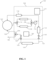
- FIG. 1 is a simplified block flow diagram of a system 100 for testing, validating, or calibrating a portion of an agricultural implement, such as a liquid flow meter for a fertilizer applicator.
- the system 100 can be used in combination with a reservoir 102 (e.g., a 19 Liter (5-gallon) bucket containing water) to test a device 104 (e.g., a flow meter).
- FIG. 2 through FIG. 4 show simplified perspective views of certain parts of the system 100, and illustrate how the system 100 may be constructed and packaged.
- the system 100 includes a frame 106 containing components that may be used to test the device 104.
- the frame 106 is configured to receive the device 104, such as with hooks, a shelf or tray 202 ( FIG. 2 ), etc., and fluid connections, discussed further below.
- the system 100 includes one or more filters 108.
- the system 100 includes two filters 108 arranged in parallel.
- One or more valves 110 may be configured to direct flow to one filter 108 or the other.
- one filter 108 may be configured to preferentially remove particles of one diameter, and the other filter 108 may be configured to preferentially remove particles of another diameter.
- filters 108 may be arranged in series, such that flow passes through each filter 108.
- the fluid is drawn through the filters 108 by a pump 112 having a pump inlet and a pump outlet, and may be controlled and/or powered by an electronics module 114.
- the fluid leaving the pump outlet may flow either through a pressure relief valve 116 and back to the reservoir 102, or toward the device 104.
- the pressure relief valve 116 may be set to permit a certain threshold pressure of fluid flowing through the device 104, and whenever the pressure provided by the pump 112 exceeds that threshold pressure, any excess fluid is diverted through the pressure relief valve 116.
- the pressure relief valve 116 may be adjustable, such that a user of the system 100 may adjust the pressure of fluid flowing through the device 104.
- the system 100 may optionally include a flow meter 118.
- the flow meter 118 may be configured to continuously or instantaneously measure the flow of fluid from the pump outlet (other than the portion, if any, flowing through the pressure relief valve 116).
- the flow meter 118 may include multiple flow meters, such as an electronic flow meter and a visual flow indicator 204 ( FIG. 2 ) (e.g., a spinning disk, a rotameter, etc .).
- the fluid flowing through the flow meter 118 travels through an output valve 120 to a frame output tube 122 leaving the frame 106. If the flow meter 118 is omitted, the fluid may flow from the pump 112 directly to the output valve 120.
- the frame output tube 122 connects to the device 104, and the fluid flows through the device 104 to a frame return tube 124 and back into the frame 106 via a return valve 126.
- the fluid then returns to the reservoir 102 via a recycle flow outlet 128, or, depending on the position of a calibration valve 134, to a waste flow outlet 132.
- the waste flow outlet 132 is used for a timed catch test to determine the volumetric flow rate of the fluid through the device 104, described below, but may be used any time the fluid is not to be recycled.
- the frame 106 may, in some embodiments, carry a user interface 130 through which a user may interact with the system 100.
- the electronics module 114 may be configured to provide electrical power and/or data connections to the user interface 130, the pump 112, the flow meter 118, the device 104 being tested, or any other electrical components.
- the user interface 130 may provide information and/or controls related to the components of the system 100.
- the user interface 130 may indicate the volumetric flow of fluid through the flow meter 118 and the pressure of the fluid in the flow meter 118.
- the user interface 130 may also allow a user to adjust the threshold pressure of the pressure relief valve 116, the speed of the pump 112, the position of the valves 110, etc.
- the user interface 130 may receive information from the device 104, such as calculated flow and pressure, calibration parameters, etc.
- the user interface 130 may be configured to transmit information to the device 104, such as new calibration parameters.
- Information may be transferred between the user interface 130 and the device 104 via wireless communication or a wiring harness.
- communication with the device 104 may be via a controller or other device associated with the agricultural implement on which the device 104 is installed.
- the user interface 130 may be omitted, and information related to the flow and pressure of the fluid may be transmitted by the electronics module 114 to an external device (e.g., a computer, a mobile telephone, an iPad, a tractor, etc .)
- an external device e.g., a computer, a mobile telephone, an iPad, a tractor, etc .
- the system 100 may be used as a mobile testing system for agricultural implements.
- the system 100 may be used to test devices that measure and control liquid flow, such as those described in U.S. Patent Application Publication 2018/0263180, "Systems and Devices for Controlling and Monitoring Liquid Applications of Agricultural Fields," published September 20, 2018 .
- FIG. 5 is a simplified flow chart illustrating a method 500 in which the system 100 may be used for testing, calibrating, or validating an agricultural implement or a portion thereof.
- a device 104 is connected to the frame output tube 122 and to the frame return tube 124.
- the device 104 may be removed from the agricultural implement before testing, either physically or by simply disconnecting its fluid connections.
- the output valve 120 and the return valve 126 may be closed while connecting the device 104 so that the fluid being pumped by the pump 112 passes through the pressure relief valve 116, rather than through the output valve 120.
- the device 104 may be connected while the pump 112 is operating.
- fluid is pumped from the frame output tube 122 to the frame return tube 124 through the device 104 being tested (e.g., by opening the output valve 120 and the return valve 126).
- the flow rate of the fluid may be changed using the device 102 (if the device 102 includes a flow-control mechanism), adjusting the output valve 120, and/or adjusting the pressure relief valve 116.
- a flow rate of the fluid is measured, typically by measuring an electronic output from the device 104, using the flow meter 118, and/or by diverting fluid from the reservoir 102 to another container for a period of time.
- a timed catch test may be performed by turning the calibration valve 134 and diverting the fluid flow from the recycle flow outlet 128 to another container of known volume via the waste flow outlet 132.
- the time to fill that container may be measured (e.g ., with a stopwatch or with a timer on the user interface 130), and a volumetric flow rate may be calculated by dividing the volume by the time.
- Various parameters of the device 104 may be tested while fluid is flowing through the device 104, such as pressure sensors, temperature sensors, operation of flow controls, or any other sensors or controls in the device 104.
- the device 104 is disconnected from the frame output tube 122 and the frame return tube 124 (e.g., by first closing the output valve 120 and the return valve 126).
- the method 500 may also include testing additional devices.
- a second device is connected to the frame output tube 122 and the frame return tube 124.
- the fluid is pumped from the frame output tube 122 to the frame return tube 124 through the second device.
- a flow rate of the fluid is measured.
- the second device may then be disconnected and reinstalled on an agricultural implement. Thus, multiple devices may be tested quickly using the system 100, without turning the pump 112 off and back on.
Description
- Embodiments of the present disclosure relate generally to test systems and methods for validating and calibrating agricultural equipment, such as planters, fertilizer applicators, etc.
- Crop yields are affected by a variety of factors, such as seed placement, soil quality, weather, irrigation, and nutrient applications. Seeds are typically planted in trenches formed by discs or other mechanisms of a planter row unit.
- Adding materials (such as fertilizers) adjacent to seed trenches during planting is a good way to deliver the materials to the soil for growing plants to access the material during a later growing stage. This eliminates a pass over the field to reduce compaction of the soil from separate planting and material application passes. Some of the fertilizer is placed adjacent to the seed trench, and when the plant grows and extends into the zone where the fertilizer was placed, the plant can then use the fertilizer.
- There are various implements that deliver fertilizer to soil adjacent to the trench on a planter row unit. These implements generally have coulters or knives to open a space adjacent the trench and include a liquid delivery tube for delivering fertilizer. The amount of liquid is controlled to control the amount of fertilizer. Such implements are described in, for example,
U. S. Patent Application Publication 2018/0263180, "Systems and Devices for Controlling and Monitoring Liquid Applications of Agricultural Fields," published September 20, 2018 ;U.S. Patent Application Publication 2019/0254226, "Systems, Methods, and Apparatus for Agricultural Material Application," published August 22, 2019 ; andU.S. Patent Application Publication 2019/0246556, "Implements and Application Units Having a Fluid Applicator with Nozzles for Placement of Applications with Respect to Agricultural Plants of Agricultural Fields," published August 15, 2019 . -
DE 2410608 A1 discloses a test instrument for a hydraulic system, which uses a hydraulic gear pump to measure throughput with a tachometer on a pump shaft. The test instrument comprises a housing with a test line connected to the hydraulic gear pump as a throughflow quantity measuring device. The test line comprises an inlet, a pressure filter, measuring instruments and a throttle. An outlet of the test line can be connected to an oil reservoir or an inlet of a tractor pump. -
US 2019/197793 A1 discloses an irrigation sprinkler head tester comprising a cabinet with a water reservoir and submersible pump, the submersible pump located in the water reservoir in the bottom of the cabinet, the top section of the cabinet equipped with doors with transparent panels to observe the sprinkler head as it is being tested. -
US 3 942 375 A discloses a system according to the preamble of claim 1. - In accordance with a first aspect of the invention there is provided a system for testing an agricultural implement that includes a frame configured to receive a device to be tested. The frame carries a filter, a pump having a pump inlet and a pump outlet, a pressure relief valve in fluid communication with the pump outlet, a frame output tube to deliver the flow of fluid from the pump outlet to the device to be tested, a frame return tube to receive the flow of fluid from the device to be tested, and a recycle flow outlet. Each of the pump, the filter, the pressure relief valve, the frame output tube, the frame return tube, and the recycle flow outlet are secured to the frame.
- In accordance with a second aspect of the invention there is provided a method for testing an agricultural implement that includes connecting a device to the frame output tube, connecting the device to the frame return tube, pumping a fluid from the frame output tube to the frame return tube through the device, and measuring a flow rate of the fluid through the device.
- While the specification concludes with claims particularly pointing out and distinctly claiming what are regarded as embodiments of the present disclosure, various features and advantages of embodiments of the disclosure may be more readily ascertained from the following description of example embodiments of the disclosure when read in conjunction with the accompanying drawings, in which:
-
FIG. 1 is a simplified block flow diagram of a system for testing an agricultural implement according to the invention; -
FIG. 2 is a simplified perspective view of the system illustrated inFIG. 1 ; -
FIG. 3 is another simplified perspective view of the system illustrated inFIG. 1 ; -
FIG. 4 is another simplified perspective view of the system illustrated inFIG. 1 ; and -
FIG. 5 is a simplified flow chart illustrating a method of testing an agricultural implement according to the invention. - The illustrations presented herein are not actual views of any planter or portion thereof, but are merely idealized representations that are employed to describe example embodiments of the present disclosure. Additionally, elements common between figures may retain the same numerical designation.
- The following description provides specific details of embodiments of the present disclosure in order to provide a thorough description thereof. However, a person of ordinary skill in the art will understand that the embodiments of the disclosure may be practiced without employing many such specific details. Indeed, the embodiments of the disclosure may be practiced in conjunction with conventional techniques employed in the industry. In addition, the description provided below does not include all elements to form a complete structure or assembly. Only those process acts and structures necessary to understand the embodiments of the disclosure are described in detail below. Additional conventional acts and structures may be used. Also note, the drawings accompanying the application are for illustrative purposes only, and are thus not drawn to scale.
- As used herein, the terms "comprising," "including," "containing," "characterized by," and grammatical equivalents thereof are inclusive or open-ended terms that do not exclude additional, unrecited elements or method steps, but also include the more restrictive terms "consisting of" and "consisting essentially of" and grammatical equivalents thereof.
- As used herein, the term "may" with respect to a material, structure, feature, or method act indicates that such is contemplated for use in implementation of an embodiment of the disclosure, and such term is used in preference to the more restrictive term "is" so as to avoid any implication that other, compatible materials, structures, features, and methods usable in combination therewith should or must be excluded.
- As used herein, the term "configured" refers to a size, shape, material composition, and arrangement of one or more of at least one structure and at least one apparatus facilitating operation of one or more of the structure and the apparatus in a predetermined way.
- As used herein, the singular forms following "a," "an," and "the" are intended to include the plural forms as well, unless the context clearly indicates otherwise.
- As used herein, the term "and/or" includes any and all combinations of one or more of the associated listed items.
- As used herein, spatially relative terms, such as "beneath," "below," "lower," "bottom," "above," "upper," "top," "front," "rear," "left," "right," and the like, may be used for ease of description to describe one element's or feature's relationship to another element(s) or feature(s) as illustrated in the figures. Unless otherwise specified, the spatially relative terms are intended to encompass different orientations of the materials in addition to the orientation depicted in the figures.
- As used herein, the term "substantially" in reference to a given parameter, property, or condition means and includes to a degree that one of ordinary skill in the art would understand that the given parameter, property, or condition is met with a degree of variance, such as within acceptable manufacturing tolerances. By way of example, depending on the particular parameter, property, or condition that is substantially met, the parameter, property, or condition may be at least 90.0% met, at least 95.0% met, at least 99.0% met, or even at least 99.9% met.
- As used herein, the term "about" used in reference to a given parameter is inclusive of the stated value and has the meaning dictated by the context (e.g., it includes the degree of error associated with measurement of the given parameter).
-
FIG. 1 is a simplified block flow diagram of asystem 100 for testing, validating, or calibrating a portion of an agricultural implement, such as a liquid flow meter for a fertilizer applicator. In particular, thesystem 100 can be used in combination with a reservoir 102 (e.g., a 19 Liter (5-gallon) bucket containing water) to test a device 104 (e.g., a flow meter).FIG. 2 through FIG. 4 show simplified perspective views of certain parts of thesystem 100, and illustrate how thesystem 100 may be constructed and packaged. - The
system 100 includes aframe 106 containing components that may be used to test thedevice 104. Typically, theframe 106 is configured to receive thedevice 104, such as with hooks, a shelf or tray 202 (FIG. 2 ), etc., and fluid connections, discussed further below. Thesystem 100 includes one ormore filters 108. For example, and as shown inFIG. 1 , thesystem 100 includes twofilters 108 arranged in parallel. One ormore valves 110 may be configured to direct flow to onefilter 108 or the other. For example, onefilter 108 may be configured to preferentially remove particles of one diameter, and theother filter 108 may be configured to preferentially remove particles of another diameter. In some embodiments,filters 108 may be arranged in series, such that flow passes through eachfilter 108. - The fluid is drawn through the
filters 108 by apump 112 having a pump inlet and a pump outlet, and may be controlled and/or powered by anelectronics module 114. The fluid leaving the pump outlet may flow either through apressure relief valve 116 and back to thereservoir 102, or toward thedevice 104. Typically, thepressure relief valve 116 may be set to permit a certain threshold pressure of fluid flowing through thedevice 104, and whenever the pressure provided by thepump 112 exceeds that threshold pressure, any excess fluid is diverted through thepressure relief valve 116. Thepressure relief valve 116 may be adjustable, such that a user of thesystem 100 may adjust the pressure of fluid flowing through thedevice 104. - The
system 100 may optionally include aflow meter 118. If present, theflow meter 118 may be configured to continuously or instantaneously measure the flow of fluid from the pump outlet (other than the portion, if any, flowing through the pressure relief valve 116). In some embodiments, theflow meter 118 may include multiple flow meters, such as an electronic flow meter and a visual flow indicator 204 (FIG. 2 ) (e.g., a spinning disk, a rotameter, etc.). The fluid flowing through theflow meter 118 travels through anoutput valve 120 to aframe output tube 122 leaving theframe 106. If theflow meter 118 is omitted, the fluid may flow from thepump 112 directly to theoutput valve 120. During a test, theframe output tube 122 connects to thedevice 104, and the fluid flows through thedevice 104 to aframe return tube 124 and back into theframe 106 via areturn valve 126. The fluid then returns to thereservoir 102 via arecycle flow outlet 128, or, depending on the position of acalibration valve 134, to awaste flow outlet 132. Thus, the fluid in thereservoir 102 may be reused. Typically, thewaste flow outlet 132 is used for a timed catch test to determine the volumetric flow rate of the fluid through thedevice 104, described below, but may be used any time the fluid is not to be recycled. - The
frame 106 may, in some embodiments, carry auser interface 130 through which a user may interact with thesystem 100. Theelectronics module 114 may be configured to provide electrical power and/or data connections to theuser interface 130, thepump 112, theflow meter 118, thedevice 104 being tested, or any other electrical components. Theuser interface 130 may provide information and/or controls related to the components of thesystem 100. For example, theuser interface 130 may indicate the volumetric flow of fluid through theflow meter 118 and the pressure of the fluid in theflow meter 118. Theuser interface 130 may also allow a user to adjust the threshold pressure of thepressure relief valve 116, the speed of thepump 112, the position of thevalves 110, etc. In some embodiments, theuser interface 130 may receive information from thedevice 104, such as calculated flow and pressure, calibration parameters, etc. Theuser interface 130 may be configured to transmit information to thedevice 104, such as new calibration parameters. Information may be transferred between theuser interface 130 and thedevice 104 via wireless communication or a wiring harness. In some embodiments, communication with thedevice 104 may be via a controller or other device associated with the agricultural implement on which thedevice 104 is installed. In certain embodiments, theuser interface 130 may be omitted, and information related to the flow and pressure of the fluid may be transmitted by theelectronics module 114 to an external device (e.g., a computer, a mobile telephone, an iPad, a tractor, etc.) - Each of the components shown in
FIG. 1 and described above, with the exception of thedevice 104 and thereservoir 102, are typically secured to theframe 106, such that thesystem 100 may be easily transported from place to place. Thus, thesystem 100 may be used as a mobile testing system for agricultural implements. For example, thesystem 100 may be used to test devices that measure and control liquid flow, such as those described inU.S. Patent Application Publication 2018/0263180, "Systems and Devices for Controlling and Monitoring Liquid Applications of Agricultural Fields," published September 20, 2018 . -
FIG. 5 is a simplified flow chart illustrating amethod 500 in which thesystem 100 may be used for testing, calibrating, or validating an agricultural implement or a portion thereof. - In
block 502, adevice 104 is connected to theframe output tube 122 and to theframe return tube 124. Typically, thedevice 104 may be removed from the agricultural implement before testing, either physically or by simply disconnecting its fluid connections. Theoutput valve 120 and thereturn valve 126 may be closed while connecting thedevice 104 so that the fluid being pumped by thepump 112 passes through thepressure relief valve 116, rather than through theoutput valve 120. Thus, thedevice 104 may be connected while thepump 112 is operating. - In
block 504, fluid is pumped from theframe output tube 122 to theframe return tube 124 through thedevice 104 being tested (e.g., by opening theoutput valve 120 and the return valve 126). The flow rate of the fluid may be changed using the device 102 (if thedevice 102 includes a flow-control mechanism), adjusting theoutput valve 120, and/or adjusting thepressure relief valve 116. - In
block 506, a flow rate of the fluid is measured, typically by measuring an electronic output from thedevice 104, using theflow meter 118, and/or by diverting fluid from thereservoir 102 to another container for a period of time. For example, a timed catch test may be performed by turning thecalibration valve 134 and diverting the fluid flow from therecycle flow outlet 128 to another container of known volume via thewaste flow outlet 132. The time to fill that container may be measured (e.g., with a stopwatch or with a timer on the user interface 130), and a volumetric flow rate may be calculated by dividing the volume by the time. Various parameters of thedevice 104 may be tested while fluid is flowing through thedevice 104, such as pressure sensors, temperature sensors, operation of flow controls, or any other sensors or controls in thedevice 104. - In
block 508, thedevice 104 is disconnected from theframe output tube 122 and the frame return tube 124 (e.g., by first closing theoutput valve 120 and the return valve 126). - The
method 500 may also include testing additional devices. Inblock 510, a second device is connected to theframe output tube 122 and theframe return tube 124. Inblock 512, the fluid is pumped from theframe output tube 122 to theframe return tube 124 through the second device. Inblock 514, a flow rate of the fluid is measured. The second device may then be disconnected and reinstalled on an agricultural implement. Thus, multiple devices may be tested quickly using thesystem 100, without turning thepump 112 off and back on. - While the present disclosure has been described herein with respect to certain illustrated embodiments, those of ordinary skill in the art will recognize and appreciate that it is not so limited. Rather, many additions, deletions, and modifications to the illustrated embodiments may be made without departing from the scope of the appended claims. Further, embodiments of the disclosure have utility with different and various machine types and configurations.
Claims (13)
- A system (100) for testing an agricultural implement, the system comprising:a frame (106) configured to receive a device (104) to be tested, the frame (106) carrying:a filter (108);a pump (112) having a pump inlet and a pump outlet;a pressure relief valve (116) in fluid communication with the pump outlet;a frame output tube (122) to deliver a flow of fluid from the pump outlet to the device to be tested; anda frame return tube (124) to receive the flow of fluid from the device (104) to be tested;wherein each of the pump (112), the filter (108), the pressure relief valve (116), the frame output tube (122), and the frame return tube (124) are secured to the frame (106);characterised in that the frame (106) further carries a recycle flow outlet (128) being secured to the frame (106).
- The system (100) of claim 1, further comprising a visual flow indicator (204) secured to the frame (106) and configured to measure the flow of fluid from the pump outlet to the device (104) to be tested.
- The system (100) of claim 1 or claim 2, further comprising a flow meter (118) secured to the frame (106) and configured to measure the flow of fluid from the pump outlet to the device (104) to be tested.
- The system (100) of any one of claim 1 through claim 3, further comprising a plurality of valves (110) secured to the frame (106) and accessible from an exterior of the frame (106).
- The system (100) of claim 4, wherein the plurality of valves (110) comprises a calibration valve (134) configured to direct the flow of fluid through the recycle flow outlet (128) when the calibration valve (134) is in a first position and toward a waste flow outlet (132) when the calibration valve (134) is in a second position.
- The system (100) of claim 4 or claim 5, when dependent on claim 3, wherein the plurality of valves (110) comprises an output valve (120) and a return valve (126), wherein:when the output valve (120) and the return valve (126) are each in a first position, the device (104) is in fluid communication with the flow meter (118) and the waste flow outlet (132), andwherein when the output valve (120) and the return valve (126) are each in a second position, the flow meter (118) is in fluid communication with the waste flow outlet (132), and the device (104) is fluidly isolated from the flow meter (118) and the waste flow outlet (132).
- A method for testing an agricultural implement, the method comprising:providing the system (100) of any one of claim 1 through claim 6;connecting a device (104) to the frame output tube (122);connecting the device (104) to the frame return tube (124);pumping a fluid from the frame output tube (122) to the frame return tube (124) through the device (104); andmeasuring a flow rate of the fluid through the device (104).
- The method of claim 7, wherein pumping a fluid comprises pumping fluid via the pump inlet from a reservoir (102) external to the system (100) and returning the fluid to the reservoir (102) via the recycle flow outlet (128).
- The method of claim 7 or claim 8, further comprising:disconnecting the device (104) from the frame output tube (122) and the frame return tube (124);connecting a second device to the frame output tube (122) and the frame return tube (124);pumping a fluid from the frame output tube (122) to the frame return tube (124) through the second device; andmeasuring a flow rate of the fluid through the second device.
- The method of any one of claims 7 to 9, wherein measuring a flow rate of the fluid through the device (104) comprises mearing a volume of fluid leaving the device (104) in a period of time.
- The method of any one of claims 7 to 10, wherein measuring a flow rate of the fluid through the device comprises measuring an electronic output from the device (104).
- The method of any one of claims 7 to 11, further comprising controlling the flow rate of the fluid using the device (104).
- The method of any one of claims 7 to 11, further comprising controlling the flow rate of the fluid by adjusting the pressure relief valve (116).
Applications Claiming Priority (2)
| Application Number | Priority Date | Filing Date | Title |
|---|---|---|---|
| US201962908138P | 2019-09-30 | 2019-09-30 | |
| PCT/IB2020/056373 WO2021064481A1 (en) | 2019-09-30 | 2020-07-07 | System and method for testing an agricultural implement |
Publications (2)
| Publication Number | Publication Date |
|---|---|
| EP4037458A1 EP4037458A1 (en) | 2022-08-10 |
| EP4037458B1 true EP4037458B1 (en) | 2023-08-30 |
Family
ID=71614927
Family Applications (1)
| Application Number | Title | Priority Date | Filing Date |
|---|---|---|---|
| EP20740404.7A Active EP4037458B1 (en) | 2019-09-30 | 2020-07-07 | System and method for testing an agricultural implement |
Country Status (7)
| Country | Link |
|---|---|
| EP (1) | EP4037458B1 (en) |
| CN (1) | CN114466586B (en) |
| AR (1) | AR120110A1 (en) |
| AU (1) | AU2020361122A1 (en) |
| BR (1) | BR112022002960A2 (en) |
| CA (1) | CA3151275A1 (en) |
| WO (1) | WO2021064481A1 (en) |
Citations (1)
| Publication number | Priority date | Publication date | Assignee | Title |
|---|---|---|---|---|
| US3942375A (en) * | 1974-10-11 | 1976-03-09 | Shepherd J D | Method and means for testing hydraulic pump |
Family Cites Families (13)
| Publication number | Priority date | Publication date | Assignee | Title |
|---|---|---|---|---|
| DE2410608A1 (en) * | 1974-03-06 | 1975-10-02 | Schroeder Friedrich Wilhelm | Test instrument for hydraulic systems - uses hydraulic gear pump to measure throughput with tachometer on pump shaft |
| CN101556181A (en) * | 2009-05-20 | 2009-10-14 | 西安东风机电有限公司 | Composite static start-stop method mass flowmeter calibration system |
| CN203083818U (en) * | 2013-01-30 | 2013-07-24 | 承德市金建检测仪器有限公司 | Comprehensive testing device for agricultural irrigation filter |
| CN203949714U (en) * | 2014-04-29 | 2014-11-19 | 南通中远船务自动化有限公司 | Boats and ships flow gauge checking apparatus |
| CN204330097U (en) * | 2015-01-12 | 2015-05-13 | 浙江精华测控设备有限公司 | Flowmeter on-line calibration device |
| BR112018005859B1 (en) | 2015-09-28 | 2021-08-24 | Precision Planting Llc | FLOW DEVICE TO CONTROL FLOW DURING AN AGRICULTURAL OPERATION, CONTROL AND MONITORING UNIT, AND IMPLEMENTATION |
| CN205300835U (en) * | 2015-12-28 | 2016-06-08 | 北航温州研究院 | Flow flow resistance coefficient detection device of valve |
| CN105973350B (en) * | 2016-04-28 | 2019-05-21 | 中国核动力研究设计院 | A kind of fluid flowmeter dynamic response characteristic self-checking unit |
| MX2019000932A (en) | 2016-07-22 | 2019-08-14 | Prec Planting Llc | Implements and application units for placement of applications with respect to agricultural plants of agricultural fields. |
| CA3036078A1 (en) | 2016-09-16 | 2018-03-22 | Precision Planting Llc | Systems, methods, and apparatus for agricultural material application |
| CN106568484B (en) * | 2016-11-02 | 2019-09-06 | 北京控制工程研究所 | A kind of control flow testing device certainly |
| US10909776B2 (en) * | 2017-12-26 | 2021-02-02 | Justin Todd Russell | Irrigation sprinkler head tester |
| CN209280099U (en) * | 2018-12-07 | 2019-08-20 | 常州市成丰流量仪表有限公司 | A kind of liquid small flowmeter calibration equipment |
-
2020
- 2020-07-07 CN CN202080067084.4A patent/CN114466586B/en active Active
- 2020-07-07 CA CA3151275A patent/CA3151275A1/en active Pending
- 2020-07-07 BR BR112022002960A patent/BR112022002960A2/en unknown
- 2020-07-07 EP EP20740404.7A patent/EP4037458B1/en active Active
- 2020-07-07 AU AU2020361122A patent/AU2020361122A1/en active Pending
- 2020-07-07 WO PCT/IB2020/056373 patent/WO2021064481A1/en unknown
- 2020-09-29 AR ARP200102698A patent/AR120110A1/en active IP Right Grant
Patent Citations (1)
| Publication number | Priority date | Publication date | Assignee | Title |
|---|---|---|---|---|
| US3942375A (en) * | 1974-10-11 | 1976-03-09 | Shepherd J D | Method and means for testing hydraulic pump |
Also Published As
| Publication number | Publication date |
|---|---|
| AU2020361122A1 (en) | 2022-03-24 |
| BR112022002960A2 (en) | 2022-05-17 |
| CN114466586A (en) | 2022-05-10 |
| AR120110A1 (en) | 2022-02-02 |
| US20220341421A1 (en) | 2022-10-27 |
| CN114466586B (en) | 2023-11-28 |
| EP4037458A1 (en) | 2022-08-10 |
| WO2021064481A1 (en) | 2021-04-08 |
| CA3151275A1 (en) | 2021-04-08 |
Similar Documents
| Publication | Publication Date | Title |
|---|---|---|
| US20210112706A1 (en) | Agricultural liquid fertilizer and chemical delivery system and method of use | |
| CA2465624C (en) | Automatic liquid fertilizer rate system | |
| EP2931018B1 (en) | Seeding machine for planting multiple seed varieties and method of calibrating same | |
| US7694638B1 (en) | Modular liquid metering system for an agricultural implement | |
| EP3332625B1 (en) | A control system and method for automatically determining characteristic for optimum machine performance | |
| US5520333A (en) | Tube metering control system | |
| US20130008361A1 (en) | Liquid fertilizer sensor system | |
| CN106664937A (en) | Water-fertilizer-integrated four-control irrigating and fertilizing system | |
| US20200344943A1 (en) | System for distributing seeds and agricultural particles | |
| US20150094916A1 (en) | Systems, methods and apparatus for multi-row agricultural implement control and monitoring | |
| WO2014093609A1 (en) | Seeding machine for planting multiple seed varieties and perscription for multiple varieties seeding machine | |
| MXPA06013563A (en) | Self calibrating meter with in-meter diffuser . | |
| EP4037458B1 (en) | System and method for testing an agricultural implement | |
| US11971029B2 (en) | Test frame and methods for fluidly testing agricultural devices | |
| Porter et al. | Laboratory evaluation of a turn compensation control system for a ground sprayer | |
| Griffiths et al. | Irrigation system evaluation | |
| CN206879423U (en) | Water-fertilizer integral four controls Irrigation and fertilization system | |
| US20230105843A1 (en) | Liquid fertilizer control systems, methods, and apparatus for agricultural implements | |
| US20220364958A1 (en) | Systems and methods for testing agricultural implements | |
| Clark et al. | Injecting chemicals into drip irrigation systems | |
| WO2016035037A1 (en) | Agricultural liquid application system | |
| Bell | Development and Evaluation of an Automated Linear Move Fertigation System for Cotton Using Active Remote Sensing | |
| US20200100424A1 (en) | System and method for metering ammonia anhydrous | |
| BR102019024965A2 (en) | agricultural spray nozzle clogging monitoring system |
Legal Events
| Date | Code | Title | Description |
|---|---|---|---|
| STAA | Information on the status of an ep patent application or granted ep patent |
Free format text: STATUS: UNKNOWN |
|
| STAA | Information on the status of an ep patent application or granted ep patent |
Free format text: STATUS: THE INTERNATIONAL PUBLICATION HAS BEEN MADE |
|
| PUAI | Public reference made under article 153(3) epc to a published international application that has entered the european phase |
Free format text: ORIGINAL CODE: 0009012 |
|
| STAA | Information on the status of an ep patent application or granted ep patent |
Free format text: STATUS: REQUEST FOR EXAMINATION WAS MADE |
|
| 17P | Request for examination filed |
Effective date: 20220502 |
|
| AK | Designated contracting states |
Kind code of ref document: A1 Designated state(s): AL AT BE BG CH CY CZ DE DK EE ES FI FR GB GR HR HU IE IS IT LI LT LU LV MC MK MT NL NO PL PT RO RS SE SI SK SM TR |
|
| DAV | Request for validation of the european patent (deleted) | ||
| DAX | Request for extension of the european patent (deleted) | ||
| GRAP | Despatch of communication of intention to grant a patent |
Free format text: ORIGINAL CODE: EPIDOSNIGR1 |
|
| STAA | Information on the status of an ep patent application or granted ep patent |
Free format text: STATUS: GRANT OF PATENT IS INTENDED |
|
| P01 | Opt-out of the competence of the unified patent court (upc) registered |
Effective date: 20230518 |
|
| INTG | Intention to grant announced |
Effective date: 20230601 |
|
| GRAS | Grant fee paid |
Free format text: ORIGINAL CODE: EPIDOSNIGR3 |
|
| GRAA | (expected) grant |
Free format text: ORIGINAL CODE: 0009210 |
|
| STAA | Information on the status of an ep patent application or granted ep patent |
Free format text: STATUS: THE PATENT HAS BEEN GRANTED |
|
| AK | Designated contracting states |
Kind code of ref document: B1 Designated state(s): AL AT BE BG CH CY CZ DE DK EE ES FI FR GB GR HR HU IE IS IT LI LT LU LV MC MK MT NL NO PL PT RO RS SE SI SK SM TR |
|
| REG | Reference to a national code |
Ref country code: GB Ref legal event code: FG4D |
|
| REG | Reference to a national code |
Ref country code: CH Ref legal event code: EP |
|
| REG | Reference to a national code |
Ref country code: DE Ref legal event code: R096 Ref document number: 602020016759 Country of ref document: DE |
|
| REG | Reference to a national code |
Ref country code: IE Ref legal event code: FG4D |
|
| REG | Reference to a national code |
Ref country code: LT Ref legal event code: MG9D |
|
| REG | Reference to a national code |
Ref country code: NL Ref legal event code: MP Effective date: 20230830 |
|
| REG | Reference to a national code |
Ref country code: AT Ref legal event code: MK05 Ref document number: 1604126 Country of ref document: AT Kind code of ref document: T Effective date: 20230830 |
|
| PG25 | Lapsed in a contracting state [announced via postgrant information from national office to epo] |
Ref country code: GR Free format text: LAPSE BECAUSE OF FAILURE TO SUBMIT A TRANSLATION OF THE DESCRIPTION OR TO PAY THE FEE WITHIN THE PRESCRIBED TIME-LIMIT Effective date: 20231201 |
|
| PG25 | Lapsed in a contracting state [announced via postgrant information from national office to epo] |
Ref country code: IS Free format text: LAPSE BECAUSE OF FAILURE TO SUBMIT A TRANSLATION OF THE DESCRIPTION OR TO PAY THE FEE WITHIN THE PRESCRIBED TIME-LIMIT Effective date: 20231230 |
|
| PG25 | Lapsed in a contracting state [announced via postgrant information from national office to epo] |
Ref country code: SE Free format text: LAPSE BECAUSE OF FAILURE TO SUBMIT A TRANSLATION OF THE DESCRIPTION OR TO PAY THE FEE WITHIN THE PRESCRIBED TIME-LIMIT Effective date: 20230830 Ref country code: RS Free format text: LAPSE BECAUSE OF FAILURE TO SUBMIT A TRANSLATION OF THE DESCRIPTION OR TO PAY THE FEE WITHIN THE PRESCRIBED TIME-LIMIT Effective date: 20230830 Ref country code: NO Free format text: LAPSE BECAUSE OF FAILURE TO SUBMIT A TRANSLATION OF THE DESCRIPTION OR TO PAY THE FEE WITHIN THE PRESCRIBED TIME-LIMIT Effective date: 20231130 Ref country code: LV Free format text: LAPSE BECAUSE OF FAILURE TO SUBMIT A TRANSLATION OF THE DESCRIPTION OR TO PAY THE FEE WITHIN THE PRESCRIBED TIME-LIMIT Effective date: 20230830 Ref country code: LT Free format text: LAPSE BECAUSE OF FAILURE TO SUBMIT A TRANSLATION OF THE DESCRIPTION OR TO PAY THE FEE WITHIN THE PRESCRIBED TIME-LIMIT Effective date: 20230830 Ref country code: IS Free format text: LAPSE BECAUSE OF FAILURE TO SUBMIT A TRANSLATION OF THE DESCRIPTION OR TO PAY THE FEE WITHIN THE PRESCRIBED TIME-LIMIT Effective date: 20231230 Ref country code: HR Free format text: LAPSE BECAUSE OF FAILURE TO SUBMIT A TRANSLATION OF THE DESCRIPTION OR TO PAY THE FEE WITHIN THE PRESCRIBED TIME-LIMIT Effective date: 20230830 Ref country code: GR Free format text: LAPSE BECAUSE OF FAILURE TO SUBMIT A TRANSLATION OF THE DESCRIPTION OR TO PAY THE FEE WITHIN THE PRESCRIBED TIME-LIMIT Effective date: 20231201 Ref country code: FI Free format text: LAPSE BECAUSE OF FAILURE TO SUBMIT A TRANSLATION OF THE DESCRIPTION OR TO PAY THE FEE WITHIN THE PRESCRIBED TIME-LIMIT Effective date: 20230830 Ref country code: AT Free format text: LAPSE BECAUSE OF FAILURE TO SUBMIT A TRANSLATION OF THE DESCRIPTION OR TO PAY THE FEE WITHIN THE PRESCRIBED TIME-LIMIT Effective date: 20230830 |
|
| PG25 | Lapsed in a contracting state [announced via postgrant information from national office to epo] |
Ref country code: PL Free format text: LAPSE BECAUSE OF FAILURE TO SUBMIT A TRANSLATION OF THE DESCRIPTION OR TO PAY THE FEE WITHIN THE PRESCRIBED TIME-LIMIT Effective date: 20230830 Ref country code: NL Free format text: LAPSE BECAUSE OF FAILURE TO SUBMIT A TRANSLATION OF THE DESCRIPTION OR TO PAY THE FEE WITHIN THE PRESCRIBED TIME-LIMIT Effective date: 20230830 |