EP4037440A1 - Plasma generation device and plasma treatment method - Google Patents
Plasma generation device and plasma treatment method Download PDFInfo
- Publication number
- EP4037440A1 EP4037440A1 EP19947409.9A EP19947409A EP4037440A1 EP 4037440 A1 EP4037440 A1 EP 4037440A1 EP 19947409 A EP19947409 A EP 19947409A EP 4037440 A1 EP4037440 A1 EP 4037440A1
- Authority
- EP
- European Patent Office
- Prior art keywords
- gas
- nozzle
- plasma
- cover
- main body
- Prior art date
- Legal status (The legal status is an assumption and is not a legal conclusion. Google has not performed a legal analysis and makes no representation as to the accuracy of the status listed.)
- Granted
Links
Images


Classifications
-
- H—ELECTRICITY
- H05—ELECTRIC TECHNIQUES NOT OTHERWISE PROVIDED FOR
- H05H—PLASMA TECHNIQUE; PRODUCTION OF ACCELERATED ELECTRICALLY-CHARGED PARTICLES OR OF NEUTRONS; PRODUCTION OR ACCELERATION OF NEUTRAL MOLECULAR OR ATOMIC BEAMS
- H05H1/00—Generating plasma; Handling plasma
- H05H1/24—Generating plasma
- H05H1/46—Generating plasma using applied electromagnetic fields, e.g. high frequency or microwave energy
- H05H1/4645—Radiofrequency discharges
- H05H1/466—Radiofrequency discharges using capacitive coupling means, e.g. electrodes
-
- H—ELECTRICITY
- H05—ELECTRIC TECHNIQUES NOT OTHERWISE PROVIDED FOR
- H05H—PLASMA TECHNIQUE; PRODUCTION OF ACCELERATED ELECTRICALLY-CHARGED PARTICLES OR OF NEUTRONS; PRODUCTION OR ACCELERATION OF NEUTRAL MOLECULAR OR ATOMIC BEAMS
- H05H1/00—Generating plasma; Handling plasma
- H05H1/24—Generating plasma
- H05H1/26—Plasma torches
- H05H1/32—Plasma torches using an arc
- H05H1/34—Details, e.g. electrodes, nozzles
- H05H1/341—Arrangements for providing coaxial protecting fluids
Definitions
- the present disclosure relates to a plasma generation device or the like for ejecting a plasma gas.
- Examples of a plasma generation device include a structure in which a processing gas that is plasmatized in a reaction chamber, and the plasma gas that is plasmatized is ejected from an ejection port formed in a nozzle or the like.
- An example of such plasma generation devices is described in the following Patent Literature.
- Patent Literature 1 International Publication No. WO2015/141768
- An object of the present specification is to improve the usefulness of a plasma generation device having a structure in which a plasma gas is ejected from an ejection port.
- a plasma generation device including: a device main body in which a reaction chamber for plasmatizing a processing gas is formed; a ceramic nozzle in which a first ejection port for ejecting a plasma gas that is plasmatized in the reaction chamber is formed; and a metal nozzle cover in which a second ejection port for ejecting a gas so as to cover the plasma gas is formed to cover the first ejection port.
- a plasma generation device including: a device main body in which a reaction chamber for plasmatizing a processing gas is formed; a nozzle in which a first ejection port for ejecting a plasma gas that is plasmatized in the reaction chamber is formed, and which is provided in the device main body; and a nozzle cover which is provided in the device main body so as to cover the nozzle, and in which a second ejection port for ejecting the plasma gas ejected from the first ejection port to an outside is formed, in which the nozzle cover includes a ceramic cover main body provided in the device main body, and a metal cover section in which the second ejection port is formed and which is provided in the cover main body.
- a plasma treatment method including: a plasma gas ejecting step of ejecting a plasma gas from a first ejection port toward a treatment target object; and a shielding gas ejecting step of shielding the plasma gas by ejecting a shielding gas from a second ejection port formed in a metal member toward the plasma gas ejected from the first ejection port.
- the present disclosure it is possible to improve the usefulness of the plasma generation device having the structure in which the plasma gas is ejected from the ejection port.
- plasma device 10 includes plasma head 11, robot 13, and control box 15.
- Plasma head 11 is attached to robot 13.
- Robot 13 is, for example, a serial link-type robot (may also be referred to as a multi-joint-type robot).
- Plasma head 11 is configured to be capable of irradiating plasma gas in a state where plasma head 11 is held at a tip of robot 13.
- Plasma head 11 is configured to be three-dimensionally movable in accordance with the driving of robot 13.
- Control box 15 is configured mainly by a computer, and collectively controls plasma device 10.
- Control box 15 has power source section 15A for supplying electric power to plasma head 11 and gas supply section 15B for supplying gas to plasma head 11.
- Power source section 15A is connected to plasma head 11 via a power cable (not illustrated).
- Power source section 15A changes a voltage to be applied to electrode 33 (refer to Figs. 3 and 4 ) of plasma head 11 based on the control of control box 15.
- Gas supply section 15B is connected to plasma head 11 via multiple (four in the present embodiment) gas tubes 19.
- Gas supply section 15B supplies a reaction gas, a carrier gas, and a heat gas, which will be described later, to plasma head 11 based on the control of control box 15.
- Control box 15 controls gas supply section 15B, and controls an amount or the like of the gas supplied from gas supply section 15B to plasma head 11. Therefore, robot 13 operates based on the control of control box 15 to irradiate treatment target object W placed on table 17 with the plasma gas from plasma head 11.
- Control box 15 includes operation section 15C having a touch panel and various switches.
- Control box 15 displays various setting screens, operation states (for example, a gas supply state, and the like), and the like on the touch panel of operation section 15C.
- control box 15 receives various types of information by operation inputs to operation section 15C.
- plasma head 11 includes plasma generation section 21, heat gas supply section 23, and the like.
- Plasma generation section 21 plasmatizes the processing gas supplied from gas supply section 15B (refer to Fig. 1 ) of control box 15 to generate plasma gas.
- Heat gas supply section 23 heats the gas supplied from gas supply section 15B to generate heat gas.
- Plasma head 11 of the present embodiment ejects the plasma gas generated in plasma generation section 21 to treatment target object W illustrated in Fig. 1 together with the heat gas generated by heat gas supply section 23.
- the processing gas is supplied to plasma head 11 from an upstream side to a downstream side in a direction of an arrow illustrated in Fig. 2 .
- Plasma head 11 may have a configuration in which heat gas supply section 23 is not provided. That is, the plasma device of the present disclosure may have a configuration in which the heat gas is not used.
- plasma generation section 21 includes head main body section 31, a pair of electrodes 33, plasma irradiation section 35, and the like.
- Fig. 3 is a sectional view cut along with positions of the pair of electrodes 33 and multiple body-side plasma paths 71 described later
- Fig. 4 is a sectional view in line AA of Fig. 3 .
- head main body section 31 is formed of ceramic having a high heat resistance
- reaction chamber 37 for generating plasma gas is formed in an inside of head main body section 31.
- Each of the pair of electrodes 33 has, for example, a cylindrical shape, and is fixed in a state where a tip portion thereof protrudes into reaction chamber 37.
- the pair of electrodes 33 may be simply referred to as electrode 33.
- a direction in which the pair of electrodes 33 are arranged is referred to as an X direction
- a direction in which plasma generation section 21 and heat gas supply section 23 are arranged is referred to as a Y direction
- an axial direction of cylindrical electrode 33 is referred to as a Z direction.
- the X direction, the Y direction, and the Z direction are directions orthogonal to each other.
- Heat gas supply section 23 includes gas pipe 41, heater 43, connection section 45, and the like. Gas pipe 41 and heater 43 are attached to an outer peripheral surface of head main body section 31 and are covered with cover 47 illustrated in Fig. 4 . Gas pipe 41 is connected to gas supply section 15B of control box 15 via gas tube 19 (refer to Fig. 1 ). Gas (for example, air) is supplied to gas pipe 41 from gas supply section 15B. Heater 43 is attached to an intermediate portion of gas pipe 41. Heater 43 warms the gas flowing through gas pipe 41 to generate heat gas.
- Gas for example, air
- connection section 45 connects gas pipe 41 to plasma irradiation section 35.
- a first end portion of connection section 45 is connected to gas pipe 41, and a second end portion thereof is connected to heat gas flow path 51 formed in plasma irradiation section 35. Heat gas is supplied to heat gas flow path 51 via gas pipe 41.
- Electrode cover 53 As illustrated in Fig. 4 , a part of an outer periphery portion of electrode 33 is covered with electrode cover 53 made of an insulator such as ceramic. Electrode cover 53 has a substantially hollow tubular shape, and openings are formed at both end portions in a longitudinal direction. A gap between an inner peripheral surface of electrode cover 53 and an outer peripheral surface of electrode 33 functions as gas flow path 55. An opening of electrode cover 53 on a downstream side is connected to reaction chamber 37. A lower end of electrode 33 protrudes from the opening of electrode cover 53 on the downstream side.
- Reaction gas flow path 61 and a pair of carrier gas flow paths 63 are formed in the inside of head main body section 31.
- Reaction gas flow path 61 is provided substantially at a center portion of head main body section 31, is connected to gas supply section 15B via gas tube 19 (refer to Fig. 1 ), and allows the reaction gas supplied from gas supply section 15B to flow into reaction chamber 37.
- the pair of carrier gas flow paths 63 are disposed at positions where reaction gas flow path 61 is interposed therebetween in the X direction.
- Each of the pair of carrier gas flow paths 63 is connected to gas supply section 15B via gas tube 19 (refer to Fig. 1 ), so that the carrier gas is supplied from gas supply section 15B.
- Carrier gas flow path 63 allows the carrier gas to flow into reaction chamber 37 via gas flow path 55.
- reaction gas oxygen (O2)
- gas supply section 15B allows, for example, a mixed gas (for example, dry air (Air)) of oxygen and nitrogen (N2) to flow into between electrodes 33 of reaction chamber 37 via reaction gas flow path 61.
- this mixed gas may be referred to as the reaction gas for convenience, and oxygen may be referred to as the refer tod gas.
- nitrogen can be employed as the carrier gas.
- Gas supply section 15B allows the carrier gas to flow from each of gas flow paths 55 so as to surround each of the pair of electrodes 33.
- An AC voltage is applied to the pair of electrodes 33 from power source section 15A of control box 15.
- pseudo arc A is generated between lower ends of the pair of electrodes 33 in reaction chamber 37.
- the reaction gas passes through pseudo arc A, the reaction gas is plasmatized. Accordingly, the pair of electrodes 33 generate discharge of pseudo arc A, plasmatize the reaction gas, and generate the plasma gas.
- multiple (six in the present embodiment) body-side plasma paths 71 arranged at intervals in the X direction and extending in the Z direction are formed in a portion of head main body section 31 on the downstream side of reaction chamber 37. An upstream end portion of each of multiple body-side plasma paths 71 is connected to reaction chamber 37.
- Plasma irradiation section 35 includes nozzle 73, nozzle cover 75, and the like.
- Nozzle 73 is generally T-shaped in side view from the X direction, and includes nozzle main body 77 and nozzle tip 79.
- Nozzle 73 is an integral object of nozzle main body 77 and nozzle tip 79, and is formed of ceramic having a high heat resistance.
- Nozzle main body 77 has a generally flange shape and is fixed to a lower surface of head main body section 31 by bolt 80.
- Nozzle tip 79 has a shape extending downward from a lower surface of nozzle main body 77.
- Nozzle 73 is formed with multiple (six in the present embodiment) nozzle-side plasma paths 81 that penetrate nozzle main body 77 and nozzle tip 79 in the vertical direction, that is, the Z direction, and multiple nozzle-side plasma paths 81 are arranged at intervals in the X direction. Multiple nozzle-side plasma paths 81 are formed at the same positions as multiple body-side plasma paths 71 in the Z direction. Therefore, body-side plasma path 71 and nozzle-side plasma path 81 communicate with each other.
- nozzle cover 75 is generally T-shaped in side view from the X direction, and includes cover main body 85 and cover tip 87.
- Cover main body 85 and cover tip 87 are separate members, cover main body 85 is formed of ceramic, and cover tip 87 is formed of metal, specifically, stainless steel.
- Cover main body 85 is generally plate-shaped in plate thickness, and recess 89 having a shape open to an upper surface and recessed in the Z direction is formed in cover main body 85.
- Cover main body 85 is fixed to the lower surface of head main body section 31 by bolts 90 so that nozzle main body 77 of nozzle 73 is housed in recess 89.
- heat gas flow path 51 is formed in cover main body 85 so as to extend in the Y direction, a first end portion of heat gas flow path 51 is open to recess 89, and a second end portion of heat gas flow path 51 is open to a side surface of cover main body 85.
- An end portion of heat gas flow path 51 that is open to the side surface of cover main body 85 is connected to connection section 45 of heat gas supply section 23.
- Cover tip 87 has a plate shape having a thickness dimension equivalent to a thickness dimension of cover main body 85, and is fixed to the lower surface of cover main body 85 by bolts 91 so as to extend downward from the lower surface of cover main body 85.
- One through-hole 93 penetrating in the Z direction is formed in cover tip 87, and an upper end portion of through-hole 93 communicates with recess 89 of cover main body 85.
- Nozzle tip 79 of nozzle 73 is inserted into through-hole 93. Therefore, nozzle 73 is entirely covered with nozzle cover 75.
- the lower end of nozzle tip 79 of nozzle 73 and the lower end of cover tip 87 of nozzle cover 75 are located at the same height.
- nozzle main body 77 of nozzle 73 is located in an inside of recess 89 of nozzle cover 75, and nozzle tip 79 of nozzle 73 is located in through-hole 93 of nozzle cover 75.
- a gap exists between recess 89 and nozzle main body 77, and between through-hole 93 and nozzle tip 79, and the gap functions as heat gas output path 95.
- the heat gas is supplied to heat gas output path 95 via heat gas flow path 51.
- the plasma gas generated in reaction chamber 37 flows through body-side plasma path 71 and nozzle-side plasma path 81 together with the carrier gas, and is ejected from opening 81A at the lower end of nozzle-side plasma path 81.
- the heat gas supplied from gas pipe 41 to heat gas flow path 51 flows through heat gas output path 95.
- the heat gas functions as a shielding gas for protecting the plasma gas.
- the heat gas flows through heat gas output path 95, and is ejected from opening 95A at the lower end of heat gas output path 95 along the ejection direction of the plasma gas.
- the heat gas is ejected so as to surround the periphery of the plasma gas ejected from opening 81A of nozzle-side plasma path 81. In this manner, by ejecting the heated heat gas to the periphery of the plasma gas, the efficiency (wettability or the like) of the plasma gas can be enhanced.
- Plasma device 10 is an example of a plasma generation device.
- Heat gas supply section 23 is an example of an ejection device.
- Head main body section 31 is an example of a device main body.
- Reaction chamber 37 is an example of a reaction chamber.
- Nozzle 73 is an example of a nozzle.
- Nozzle cover 75 is an example of a nozzle cover.
- Nozzle main body 77 is an example of a nozzle main body.
- Nozzle tip 79 is an example of a nozzle tip.
- Opening 81A of nozzle-side plasma path 81 is an example of a first ejection port.
- Cover main body 85 is an example of a cover main body.
- Cover tip 87 is an example of a cover section.
- Opening 95A of heat gas output path 95 is an example of a second ejection port.
- the heat gas is an example of the sealing gas.
- ceramic nozzle 73 is covered with nozzle cover 75 having metal cover tip 87. Therefore, it is possible to prevent nozzle 73 from being damaged. That is, since nozzle 73 is formed of ceramic, it is brittle and susceptible to damage.
- cover tip 87 serving as a tip portion of nozzle cover 75 is formed of a metal and is not easily damaged. Therefore, even when the tip of plasma head 11 comes into contact with treatment target object W or the like during the plasma irradiation by plasma head 11 or the like, nozzle 73 is protected by metal nozzle cover 75, so that nozzle 73 is prevented from being damaged.
- ceramic is relatively expensive, but metal is inexpensive. Accordingly, even if cover tip 87 is damaged, deformed, or the like, cover tip 87 can be exchanged at a reduced cost.
- nozzle cover 75 includes cover main body 85 and cover tip 87, cover main body 85 is formed of ceramic, and cover tip 87 is formed of stainless steel. Therefore, it is possible to secure appropriate plasmatization and to achieve cost reduction. That is, although the cost can be reduced by forming the entire nozzle cover with metal, if the upper end portion of the nozzle cover closer to reaction chamber 37 of head main body section 31, that is, cover main body 85 is made of metal, discharge may generate in the periphery of cover main body 85 by the application to electrode 33 in reaction chamber 37. In such a case, it is not possible to secure appropriate plasmatization by discharge in a region other than reaction chamber 37. Accordingly, cover main body 85 closer to reaction chamber 37 is formed of ceramic, and cover tip 87 distant from reaction chamber 37 is formed of metal. Therefore, it is possible to secure appropriate plasmatization and to achieve cost reduction.
- metal cover tip 87 is shaped so as to extend in a direction away from cover main body 85. That is, metal cover tip 87 has a shape extending in a direction away from reaction chamber 37. Therefore, it is possible to further suitably prevent discharge in a region other than reaction chamber 37, and it is possible to further secure appropriate plasmatization.
- Nozzle tip 79 of nozzle 73 also has a shape extending in a direction away from nozzle main body 77, that is, downward, similarly to cover tip 87 of nozzle cover 75. Nozzle tip 79 extending downward is inserted in an inside of cover tip 87 extending downward. Therefore, the plasma gas ejected from opening 81A of nozzle tip 79 can be appropriately ejected to the outside of nozzle cover 75.
- heated heat gas flows between nozzle 73 and nozzle cover 75, so that the heated heat gas is ejected to the periphery of the plasma gas. Therefore, as described above, the efficiency (wettability or the like) of the plasma gas can be enhanced.
- nozzle cover 75 may be disposed only as a cover for protecting nozzle 73.
- the plasma gas and the heat gas are ejected from one plasma head 11, but the plasma gas and the heat gas may be ejected from two heads. That is, the plasma gas may be ejected from one head, and the heat gas may be ejected from a head different from the head.
- nozzle-side plasma path 81 and heat gas output path 95 may be formed at different positions on one head, and the plasma gas and the heat gas may be ejected from the respective paths.
- nozzle 73 and nozzle cover 75 are fixed to head main body section 31, but may be simply provided. That is, nozzle main body 77 may be provided in head main body section 31. Nozzle tip 79 may also be provided in nozzle main body 77.
- plasma device plasma generation device
- 23 heat gas supply section (ejection device)
- 31 head main body section (device main body)
- 37 reaction chamber
- 73 nozzle
- 75 nozzle cover
- 77 nozzle main body
- 79 nozzle tip
- 81A opening (first ejection port)
- 85 cover main body
- 87 cover tip (cover section)
- 95A opening (second ejection port)
Landscapes
- Physics & Mathematics (AREA)
- Engineering & Computer Science (AREA)
- Plasma & Fusion (AREA)
- Electromagnetism (AREA)
- Spectroscopy & Molecular Physics (AREA)
- Plasma Technology (AREA)
Abstract
Description
- The present disclosure relates to a plasma generation device or the like for ejecting a plasma gas.
- Examples of a plasma generation device include a structure in which a processing gas that is plasmatized in a reaction chamber, and the plasma gas that is plasmatized is ejected from an ejection port formed in a nozzle or the like. An example of such plasma generation devices is described in the following Patent Literature.
- Patent Literature 1: International Publication No.
WO2015/141768 - An object of the present specification is to improve the usefulness of a plasma generation device having a structure in which a plasma gas is ejected from an ejection port.
- In order to solve the above-mentioned problems, the present specification discloses a plasma generation device including: a device main body in which a reaction chamber for plasmatizing a processing gas is formed; a ceramic nozzle in which a first ejection port for ejecting a plasma gas that is plasmatized in the reaction chamber is formed; and a metal nozzle cover in which a second ejection port for ejecting a gas so as to cover the plasma gas is formed to cover the first ejection port.
- In addition, the present specification discloses a plasma generation device including: a device main body in which a reaction chamber for plasmatizing a processing gas is formed; a nozzle in which a first ejection port for ejecting a plasma gas that is plasmatized in the reaction chamber is formed, and which is provided in the device main body; and a nozzle cover which is provided in the device main body so as to cover the nozzle, and in which a second ejection port for ejecting the plasma gas ejected from the first ejection port to an outside is formed, in which the nozzle cover includes a ceramic cover main body provided in the device main body, and a metal cover section in which the second ejection port is formed and which is provided in the cover main body.
- In addition, the present specification discloses a plasma treatment method including: a plasma gas ejecting step of ejecting a plasma gas from a first ejection port toward a treatment target object; and a shielding gas ejecting step of shielding the plasma gas by ejecting a shielding gas from a second ejection port formed in a metal member toward the plasma gas ejected from the first ejection port.
- According to the present disclosure, it is possible to improve the usefulness of the plasma generation device having the structure in which the plasma gas is ejected from the ejection port.
-
-
Fig. 1 is a view illustrating a plasma device. -
Fig. 2 is a perspective view illustrating a plasma head. -
Fig. 3 is a sectional view of the plasma head cut in an X direction and a Z direction at positions of an electrode and a body-side plasma path. -
Fig. 4 is a sectional view in line AA ofFig. 3 . -
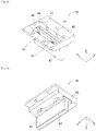
Fig. 5 is a perspective view of a nozzle cover. -
Fig. 6 is a perspective view of a nozzle cover. - Hereinafter, as exemplary embodiments of the present invention, examples of the present invention will be described in detail with reference to the drawings.
- As illustrated in
Fig. 1 ,plasma device 10 includesplasma head 11,robot 13, andcontrol box 15.Plasma head 11 is attached torobot 13. Robot 13 is, for example, a serial link-type robot (may also be referred to as a multi-joint-type robot).Plasma head 11 is configured to be capable of irradiating plasma gas in a state whereplasma head 11 is held at a tip ofrobot 13.Plasma head 11 is configured to be three-dimensionally movable in accordance with the driving ofrobot 13. -
Control box 15 is configured mainly by a computer, and collectively controlsplasma device 10.Control box 15 haspower source section 15A for supplying electric power toplasma head 11 andgas supply section 15B for supplying gas toplasma head 11.Power source section 15A is connected toplasma head 11 via a power cable (not illustrated).Power source section 15A changes a voltage to be applied to electrode 33 (refer toFigs. 3 and4 ) ofplasma head 11 based on the control ofcontrol box 15. -
Gas supply section 15B is connected toplasma head 11 via multiple (four in the present embodiment)gas tubes 19.Gas supply section 15B supplies a reaction gas, a carrier gas, and a heat gas, which will be described later, toplasma head 11 based on the control ofcontrol box 15.Control box 15 controlsgas supply section 15B, and controls an amount or the like of the gas supplied fromgas supply section 15B toplasma head 11. Therefore,robot 13 operates based on the control ofcontrol box 15 to irradiate treatment target object W placed on table 17 with the plasma gas fromplasma head 11. -
Control box 15 includesoperation section 15C having a touch panel and various switches.Control box 15 displays various setting screens, operation states (for example, a gas supply state, and the like), and the like on the touch panel ofoperation section 15C. In addition,control box 15 receives various types of information by operation inputs tooperation section 15C. - As illustrated in
Fig. 2 ,plasma head 11 includesplasma generation section 21, heatgas supply section 23, and the like.Plasma generation section 21 plasmatizes the processing gas supplied fromgas supply section 15B (refer toFig. 1 ) ofcontrol box 15 to generate plasma gas. Heatgas supply section 23 heats the gas supplied fromgas supply section 15B to generate heat gas.Plasma head 11 of the present embodiment ejects the plasma gas generated inplasma generation section 21 to treatment target object W illustrated inFig. 1 together with the heat gas generated by heatgas supply section 23. The processing gas is supplied toplasma head 11 from an upstream side to a downstream side in a direction of an arrow illustrated inFig. 2 .Plasma head 11 may have a configuration in which heatgas supply section 23 is not provided. That is, the plasma device of the present disclosure may have a configuration in which the heat gas is not used. - As illustrated in
Fig. 3 andFig. 4 ,plasma generation section 21 includes headmain body section 31, a pair ofelectrodes 33,plasma irradiation section 35, and the like.Fig. 3 is a sectional view cut along with positions of the pair ofelectrodes 33 and multiple body-side plasma paths 71 described later, andFig. 4 is a sectional view in line AA ofFig. 3 . headmain body section 31 is formed of ceramic having a high heat resistance, andreaction chamber 37 for generating plasma gas is formed in an inside of headmain body section 31. Each of the pair ofelectrodes 33 has, for example, a cylindrical shape, and is fixed in a state where a tip portion thereof protrudes intoreaction chamber 37. In the following description, the pair ofelectrodes 33 may be simply referred to aselectrode 33. In addition, a direction in which the pair ofelectrodes 33 are arranged is referred to as an X direction, a direction in whichplasma generation section 21 and heatgas supply section 23 are arranged is referred to as a Y direction, and an axial direction ofcylindrical electrode 33 is referred to as a Z direction. In the present embodiment, the X direction, the Y direction, and the Z direction are directions orthogonal to each other. - Heat
gas supply section 23 includesgas pipe 41,heater 43,connection section 45, and the like.Gas pipe 41 andheater 43 are attached to an outer peripheral surface of headmain body section 31 and are covered withcover 47 illustrated inFig. 4 .Gas pipe 41 is connected togas supply section 15B ofcontrol box 15 via gas tube 19 (refer toFig. 1 ). Gas (for example, air) is supplied togas pipe 41 fromgas supply section 15B.Heater 43 is attached to an intermediate portion ofgas pipe 41. Heater 43 warms the gas flowing throughgas pipe 41 to generate heat gas. - As illustrated in
Fig. 4 ,connection section 45 connectsgas pipe 41 toplasma irradiation section 35. In a state whereplasma irradiation section 35 is attached to headmain body section 31, a first end portion ofconnection section 45 is connected togas pipe 41, and a second end portion thereof is connected to heatgas flow path 51 formed inplasma irradiation section 35. Heat gas is supplied to heatgas flow path 51 viagas pipe 41. - As illustrated in
Fig. 4 , a part of an outer periphery portion ofelectrode 33 is covered withelectrode cover 53 made of an insulator such as ceramic.Electrode cover 53 has a substantially hollow tubular shape, and openings are formed at both end portions in a longitudinal direction. A gap between an inner peripheral surface ofelectrode cover 53 and an outer peripheral surface ofelectrode 33 functions asgas flow path 55. An opening ofelectrode cover 53 on a downstream side is connected toreaction chamber 37. A lower end ofelectrode 33 protrudes from the opening ofelectrode cover 53 on the downstream side. - Reaction
gas flow path 61 and a pair of carriergas flow paths 63 are formed in the inside of headmain body section 31. Reactiongas flow path 61 is provided substantially at a center portion of headmain body section 31, is connected togas supply section 15B via gas tube 19 (refer toFig. 1 ), and allows the reaction gas supplied fromgas supply section 15B to flow intoreaction chamber 37. The pair of carriergas flow paths 63 are disposed at positions where reactiongas flow path 61 is interposed therebetween in the X direction. Each of the pair of carriergas flow paths 63 is connected togas supply section 15B via gas tube 19 (refer toFig. 1 ), so that the carrier gas is supplied fromgas supply section 15B. Carriergas flow path 63 allows the carrier gas to flow intoreaction chamber 37 viagas flow path 55. - As the reaction gas (refer tod gas), oxygen (O2) can be employed.
Gas supply section 15B allows, for example, a mixed gas (for example, dry air (Air)) of oxygen and nitrogen (N2) to flow into betweenelectrodes 33 ofreaction chamber 37 via reactiongas flow path 61. Hereinafter, this mixed gas may be referred to as the reaction gas for convenience, and oxygen may be referred to as the refer tod gas. As the carrier gas, nitrogen can be employed.Gas supply section 15B allows the carrier gas to flow from each ofgas flow paths 55 so as to surround each of the pair ofelectrodes 33. - An AC voltage is applied to the pair of
electrodes 33 frompower source section 15A ofcontrol box 15. By applying the voltage, for example, as illustrated inFig. 4 , pseudo arc A is generated between lower ends of the pair ofelectrodes 33 inreaction chamber 37. When the reaction gas passes through pseudo arc A, the reaction gas is plasmatized. Accordingly, the pair ofelectrodes 33 generate discharge of pseudo arc A, plasmatize the reaction gas, and generate the plasma gas. - In addition, multiple (six in the present embodiment) body-
side plasma paths 71 arranged at intervals in the X direction and extending in the Z direction are formed in a portion of headmain body section 31 on the downstream side ofreaction chamber 37. An upstream end portion of each of multiple body-side plasma paths 71 is connected toreaction chamber 37. -
Plasma irradiation section 35 includesnozzle 73,nozzle cover 75, and the like.Nozzle 73 is generally T-shaped in side view from the X direction, and includes nozzlemain body 77 andnozzle tip 79.Nozzle 73 is an integral object of nozzlemain body 77 andnozzle tip 79, and is formed of ceramic having a high heat resistance. Nozzlemain body 77 has a generally flange shape and is fixed to a lower surface of headmain body section 31 bybolt 80.Nozzle tip 79 has a shape extending downward from a lower surface of nozzlemain body 77.Nozzle 73 is formed with multiple (six in the present embodiment) nozzle-side plasma paths 81 that penetrate nozzlemain body 77 andnozzle tip 79 in the vertical direction, that is, the Z direction, and multiple nozzle-side plasma paths 81 are arranged at intervals in the X direction. Multiple nozzle-side plasma paths 81 are formed at the same positions as multiple body-side plasma paths 71 in the Z direction. Therefore, body-side plasma path 71 and nozzle-side plasma path 81 communicate with each other. - As illustrated in
Figs. 4 to 6 ,nozzle cover 75 is generally T-shaped in side view from the X direction, and includes covermain body 85 andcover tip 87. Covermain body 85 andcover tip 87 are separate members, covermain body 85 is formed of ceramic, andcover tip 87 is formed of metal, specifically, stainless steel. - Cover
main body 85 is generally plate-shaped in plate thickness, andrecess 89 having a shape open to an upper surface and recessed in the Z direction is formed in covermain body 85. Covermain body 85 is fixed to the lower surface of headmain body section 31 bybolts 90 so that nozzlemain body 77 ofnozzle 73 is housed inrecess 89. In addition, heatgas flow path 51 is formed in covermain body 85 so as to extend in the Y direction, a first end portion of heatgas flow path 51 is open to recess 89, and a second end portion of heatgas flow path 51 is open to a side surface of covermain body 85. An end portion of heatgas flow path 51 that is open to the side surface of covermain body 85 is connected toconnection section 45 of heatgas supply section 23. -
Cover tip 87 has a plate shape having a thickness dimension equivalent to a thickness dimension of covermain body 85, and is fixed to the lower surface of covermain body 85 bybolts 91 so as to extend downward from the lower surface of covermain body 85. One through-hole 93 penetrating in the Z direction is formed incover tip 87, and an upper end portion of through-hole 93 communicates withrecess 89 of covermain body 85.Nozzle tip 79 ofnozzle 73 is inserted into through-hole 93. Therefore,nozzle 73 is entirely covered withnozzle cover 75. The lower end ofnozzle tip 79 ofnozzle 73 and the lower end ofcover tip 87 ofnozzle cover 75 are located at the same height. - In a state where
nozzle 73 is covered withnozzle cover 75, nozzlemain body 77 ofnozzle 73 is located in an inside ofrecess 89 ofnozzle cover 75, andnozzle tip 79 ofnozzle 73 is located in through-hole 93 ofnozzle cover 75. In such a state, a gap exists betweenrecess 89 and nozzlemain body 77, and between through-hole 93 andnozzle tip 79, and the gap functions as heatgas output path 95. The heat gas is supplied to heatgas output path 95 via heatgas flow path 51. - According to such a structure, the plasma gas generated in
reaction chamber 37 flows through body-side plasma path 71 and nozzle-side plasma path 81 together with the carrier gas, and is ejected from opening 81A at the lower end of nozzle-side plasma path 81. The heat gas supplied fromgas pipe 41 to heatgas flow path 51 flows through heatgas output path 95. The heat gas functions as a shielding gas for protecting the plasma gas. The heat gas flows through heatgas output path 95, and is ejected from opening 95A at the lower end of heatgas output path 95 along the ejection direction of the plasma gas. At this time, the heat gas is ejected so as to surround the periphery of the plasma gas ejected from opening 81A of nozzle-side plasma path 81. In this manner, by ejecting the heated heat gas to the periphery of the plasma gas, the efficiency (wettability or the like) of the plasma gas can be enhanced. -
Plasma device 10 is an example of a plasma generation device. Heatgas supply section 23 is an example of an ejection device. Headmain body section 31 is an example of a device main body.Reaction chamber 37 is an example of a reaction chamber.Nozzle 73 is an example of a nozzle.Nozzle cover 75 is an example of a nozzle cover. Nozzlemain body 77 is an example of a nozzle main body.Nozzle tip 79 is an example of a nozzle tip. Opening 81A of nozzle-side plasma path 81 is an example of a first ejection port. Covermain body 85 is an example of a cover main body.Cover tip 87 is an example of a cover section. Opening 95A of heatgas output path 95 is an example of a second ejection port. The heat gas is an example of the sealing gas. - Thus, the present embodiment, which has been described heretofore, provides the following effects.
- In
plasma head 11,ceramic nozzle 73 is covered withnozzle cover 75 havingmetal cover tip 87. Therefore, it is possible to preventnozzle 73 from being damaged. That is, sincenozzle 73 is formed of ceramic, it is brittle and susceptible to damage. On the other hand,cover tip 87 serving as a tip portion ofnozzle cover 75 is formed of a metal and is not easily damaged. Therefore, even when the tip ofplasma head 11 comes into contact with treatment target object W or the like during the plasma irradiation byplasma head 11 or the like,nozzle 73 is protected bymetal nozzle cover 75, so thatnozzle 73 is prevented from being damaged. In addition, ceramic is relatively expensive, but metal is inexpensive. Accordingly, even ifcover tip 87 is damaged, deformed, or the like,cover tip 87 can be exchanged at a reduced cost. - As described above,
nozzle cover 75 includes covermain body 85 andcover tip 87, covermain body 85 is formed of ceramic, andcover tip 87 is formed of stainless steel. Therefore, it is possible to secure appropriate plasmatization and to achieve cost reduction. That is, although the cost can be reduced by forming the entire nozzle cover with metal, if the upper end portion of the nozzle cover closer toreaction chamber 37 of headmain body section 31, that is, covermain body 85 is made of metal, discharge may generate in the periphery of covermain body 85 by the application toelectrode 33 inreaction chamber 37. In such a case, it is not possible to secure appropriate plasmatization by discharge in a region other thanreaction chamber 37. Accordingly, covermain body 85 closer toreaction chamber 37 is formed of ceramic, andcover tip 87 distant fromreaction chamber 37 is formed of metal. Therefore, it is possible to secure appropriate plasmatization and to achieve cost reduction. - In other words,
metal cover tip 87 is shaped so as to extend in a direction away from covermain body 85. That is,metal cover tip 87 has a shape extending in a direction away fromreaction chamber 37. Therefore, it is possible to further suitably prevent discharge in a region other thanreaction chamber 37, and it is possible to further secure appropriate plasmatization. -
Nozzle tip 79 ofnozzle 73 also has a shape extending in a direction away from nozzlemain body 77, that is, downward, similarly to covertip 87 ofnozzle cover 75.Nozzle tip 79 extending downward is inserted in an inside ofcover tip 87 extending downward. Therefore, the plasma gas ejected from opening 81A ofnozzle tip 79 can be appropriately ejected to the outside ofnozzle cover 75. - In
plasma head 11, heated heat gas flows betweennozzle 73 andnozzle cover 75, so that the heated heat gas is ejected to the periphery of the plasma gas. Therefore, as described above, the efficiency (wettability or the like) of the plasma gas can be enhanced. - The present disclosure is not limited to the above embodiments, and can be practiced in various forms where various modifications and improvements are made based on the knowledge of those skilled in the art. Specifically, for example, in
plasma head 11, although the heat gas flows betweennozzle 73 andnozzle cover 75, the heat gas need not to flow. That is,nozzle cover 75 may be disposed only as a cover for protectingnozzle 73. - In the above embodiments, the plasma gas and the heat gas are ejected from one
plasma head 11, but the plasma gas and the heat gas may be ejected from two heads. That is, the plasma gas may be ejected from one head, and the heat gas may be ejected from a head different from the head. In addition, nozzle-side plasma path 81 and heatgas output path 95 may be formed at different positions on one head, and the plasma gas and the heat gas may be ejected from the respective paths. - In the above embodiments,
nozzle 73 and nozzle cover 75 are fixed to headmain body section 31, but may be simply provided. That is, nozzlemain body 77 may be provided in headmain body section 31.Nozzle tip 79 may also be provided in nozzlemain body 77. - 10: plasma device (plasma generation device), 23: heat gas supply section (ejection device), 31: head main body section (device main body), 37: reaction chamber, 73: nozzle, 75: nozzle cover, 77: nozzle main body, 79: nozzle tip, 81A: opening (first ejection port), 85: cover main body, 87: cover tip (cover section), 95A: opening (second ejection port)
Claims (6)
- A plasma generation device comprising:a device main body in which a reaction chamber for plasmatizing a processing gas is formed;a ceramic nozzle in which a first ejection port for ejecting a plasma gas that is plasmatized in the reaction chamber is formed; anda metal nozzle cover in which a second ejection port for ejecting a gas so as to cover the plasma gas is formed to cover the first ejection port.
- A plasma generation device comprising:a device main body in which a reaction chamber for plasmatizing a processing gas is formed;a nozzle in which a first ejection port for ejecting a plasma gas that is plasmatized in the reaction chamber is formed, and which is provided in the device main body; anda nozzle cover which is provided in the device main body so as to cover the nozzle, and in which a second ejection port for ejecting the plasma gas ejected from the first ejection port to an outside is formed;wherein the nozzle cover includesa ceramic cover main body provided in the device main body, anda metal cover section in which the second ejection port is formed and which is provided in the cover main body.
- The plasma generation device according to claim 2,
wherein the cover section has a shape extending in a direction away from the cover main body. - The plasma generation device according to claim 2 or 3,wherein the nozzle includesa nozzle main body fixed to the device main body, anda nozzle tip in which the first ejection port is formed and which is fixed to the nozzle main body, andthe nozzle tip has a shape extending in a direction away from the nozzle main body, and is inserted into the cover section.
- The plasma generation device according to any one of claims 2 to 4, further comprising:an ejection device configured to eject a shielding gas into the nozzle cover,wherein the plasma gas ejected from the second ejection port to the outside of the nozzle cover is shielded by the sealing gas.
- A plasma treatment method comprising:a plasma gas ejecting step of ejecting a plasma gas from a first ejection port toward a treatment target object; anda shielding gas ejecting step of shielding the plasma gas by ejecting a shielding gas from a second ejection port formed in a metal member toward the plasma gas ejected from the first ejection port.
Applications Claiming Priority (1)
| Application Number | Priority Date | Filing Date | Title |
|---|---|---|---|
| PCT/JP2019/038099 WO2021059469A1 (en) | 2019-09-27 | 2019-09-27 | Plasma generation device and plasma treatment method |
Publications (3)
| Publication Number | Publication Date |
|---|---|
| EP4037440A1 true EP4037440A1 (en) | 2022-08-03 |
| EP4037440A4 EP4037440A4 (en) | 2022-11-16 |
| EP4037440B1 EP4037440B1 (en) | 2025-07-02 |
Family
ID=75165628
Family Applications (1)
| Application Number | Title | Priority Date | Filing Date |
|---|---|---|---|
| EP19947409.9A Active EP4037440B1 (en) | 2019-09-27 | 2019-09-27 | Plasma generation device and plasma treatment method |
Country Status (4)
| Country | Link |
|---|---|
| EP (1) | EP4037440B1 (en) |
| JP (1) | JP7461961B2 (en) |
| CN (1) | CN114430935A (en) |
| WO (1) | WO2021059469A1 (en) |
Families Citing this family (1)
| Publication number | Priority date | Publication date | Assignee | Title |
|---|---|---|---|---|
| WO2023058215A1 (en) | 2021-10-08 | 2023-04-13 | 株式会社Fuji | Nozzle, plasma processing device, and gas jetting method |
Family Cites Families (12)
| Publication number | Priority date | Publication date | Assignee | Title |
|---|---|---|---|---|
| BE795891A (en) * | 1972-02-23 | 1973-06-18 | Electricity Council | PLASMA TORCH IMPROVEMENTS |
| JPS56126981U (en) * | 1980-02-22 | 1981-09-26 | ||
| JPS57165370U (en) * | 1981-04-09 | 1982-10-18 | ||
| US5220150A (en) * | 1991-05-03 | 1993-06-15 | Regents Of The University Of Minnesota | Plasma spray torch with hot anode and gas shroud |
| JP3066993B2 (en) * | 1991-12-24 | 2000-07-17 | オリジン電気株式会社 | Plasma arc apparatus and pilot arc generation method |
| JPH08294779A (en) * | 1995-04-21 | 1996-11-12 | Koike Sanso Kogyo Co Ltd | Plasma torch nozzle |
| US7737383B2 (en) * | 2006-08-25 | 2010-06-15 | Thermal Dynamics Corporation | Contoured shield orifice for a plasma arc torch |
| JP2008153147A (en) * | 2006-12-20 | 2008-07-03 | Seiko Epson Corp | Plasma processing equipment |
| JP5275092B2 (en) * | 2009-03-12 | 2013-08-28 | 長野日本無線株式会社 | Plasma processing equipment |
| WO2015141768A1 (en) | 2014-03-19 | 2015-09-24 | 大陽日酸株式会社 | Non-transferred plasma arc system, conversion adapter kit, and non-transferred plasma arc torch |
| CN109565921B (en) * | 2016-08-11 | 2021-05-18 | 株式会社富士 | Plasma generator and plasma irradiation method |
| CN111886934A (en) * | 2018-03-20 | 2020-11-03 | 株式会社富士 | Plasma device and plasma generating method |
-
2019
- 2019-09-27 JP JP2021548108A patent/JP7461961B2/en active Active
- 2019-09-27 EP EP19947409.9A patent/EP4037440B1/en active Active
- 2019-09-27 WO PCT/JP2019/038099 patent/WO2021059469A1/en not_active Ceased
- 2019-09-27 CN CN201980100638.3A patent/CN114430935A/en active Pending
Also Published As
| Publication number | Publication date |
|---|---|
| WO2021059469A1 (en) | 2021-04-01 |
| EP4037440A4 (en) | 2022-11-16 |
| JP7461961B2 (en) | 2024-04-04 |
| JPWO2021059469A1 (en) | 2021-04-01 |
| EP4037440B1 (en) | 2025-07-02 |
| CN114430935A (en) | 2022-05-03 |
Similar Documents
| Publication | Publication Date | Title |
|---|---|---|
| EP1893004B1 (en) | Contoured shield orifice for a plasma arc torch | |
| JP2008284580A (en) | Plasma torch | |
| CN1756617A (en) | Tip for a plasma arc torch | |
| CN102695577A (en) | Method and device for processing workpieces by means of a laser apparatus and an arc apparatus | |
| JP2010539644A (en) | Surface treatment or surface coating method and apparatus | |
| CN104704926B (en) | Asymmetric consumables for plasma arc torches | |
| CN108781499B (en) | Plasma generator | |
| JP2011523162A (en) | Equipment for processing the inner surface of workpieces | |
| EP4037440B1 (en) | Plasma generation device and plasma treatment method | |
| KR101254902B1 (en) | Plasma treatment apparatus and plasma treatment method | |
| US20060289391A1 (en) | Arc spraying torch head | |
| CA2261313A1 (en) | Electrode for a plasma torch | |
| JP2019050216A (en) | Plasma gas irradiation device | |
| JP6973429B2 (en) | Plasma device | |
| JPWO2019180839A1 (en) | Plasma device, plasma generation method | |
| JP7082937B2 (en) | Teaching nozzle | |
| JP6944066B2 (en) | Plasma generator | |
| JP2006277953A (en) | Plasma generating apparatus, plasma processing apparatus, plasma generating method, and plasma processing method | |
| JP6587689B2 (en) | Atmospheric pressure plasma generator | |
| JP2014140883A (en) | Torch, component, robot, and arc processing system | |
| JP7773559B2 (en) | Nozzle, plasma processing apparatus, and gas ejection method | |
| WO2021079420A1 (en) | Plasma generation device and plasma processing method | |
| KR102911887B1 (en) | plasma generator | |
| JP6536339B2 (en) | Welding torch, welding apparatus, and method of manufacturing welding product | |
| JP5645157B2 (en) | Plasma device |
Legal Events
| Date | Code | Title | Description |
|---|---|---|---|
| STAA | Information on the status of an ep patent application or granted ep patent |
Free format text: STATUS: THE INTERNATIONAL PUBLICATION HAS BEEN MADE |
|
| PUAI | Public reference made under article 153(3) epc to a published international application that has entered the european phase |
Free format text: ORIGINAL CODE: 0009012 |
|
| STAA | Information on the status of an ep patent application or granted ep patent |
Free format text: STATUS: REQUEST FOR EXAMINATION WAS MADE |
|
| 17P | Request for examination filed |
Effective date: 20220323 |
|
| AK | Designated contracting states |
Kind code of ref document: A1 Designated state(s): AL AT BE BG CH CY CZ DE DK EE ES FI FR GB GR HR HU IE IS IT LI LT LU LV MC MK MT NL NO PL PT RO RS SE SI SK SM TR |
|
| RIC1 | Information provided on ipc code assigned before grant |
Ipc: H05H 1/46 20060101ALI20220808BHEP Ipc: H05H 1/26 20060101AFI20220808BHEP |
|
| A4 | Supplementary search report drawn up and despatched |
Effective date: 20221017 |
|
| RIC1 | Information provided on ipc code assigned before grant |
Ipc: H05H 1/46 20060101ALI20221011BHEP Ipc: H05H 1/26 20060101AFI20221011BHEP |
|
| DAV | Request for validation of the european patent (deleted) | ||
| DAX | Request for extension of the european patent (deleted) | ||
| P01 | Opt-out of the competence of the unified patent court (upc) registered |
Effective date: 20230328 |
|
| STAA | Information on the status of an ep patent application or granted ep patent |
Free format text: STATUS: EXAMINATION IS IN PROGRESS |
|
| 17Q | First examination report despatched |
Effective date: 20240517 |
|
| GRAP | Despatch of communication of intention to grant a patent |
Free format text: ORIGINAL CODE: EPIDOSNIGR1 |
|
| STAA | Information on the status of an ep patent application or granted ep patent |
Free format text: STATUS: GRANT OF PATENT IS INTENDED |
|
| INTG | Intention to grant announced |
Effective date: 20250407 |
|
| GRAS | Grant fee paid |
Free format text: ORIGINAL CODE: EPIDOSNIGR3 |
|
| GRAA | (expected) grant |
Free format text: ORIGINAL CODE: 0009210 |
|
| STAA | Information on the status of an ep patent application or granted ep patent |
Free format text: STATUS: THE PATENT HAS BEEN GRANTED |
|
| AK | Designated contracting states |
Kind code of ref document: B1 Designated state(s): AL AT BE BG CH CY CZ DE DK EE ES FI FR GB GR HR HU IE IS IT LI LT LU LV MC MK MT NL NO PL PT RO RS SE SI SK SM TR |
|
| REG | Reference to a national code |
Ref country code: GB Ref legal event code: FG4D |
|
| REG | Reference to a national code |
Ref country code: CH Ref legal event code: EP |
|
| REG | Reference to a national code |
Ref country code: DE Ref legal event code: R096 Ref document number: 602019072157 Country of ref document: DE |
|
| REG | Reference to a national code |
Ref country code: IE Ref legal event code: FG4D |
|
| PGFP | Annual fee paid to national office [announced via postgrant information from national office to epo] |
Ref country code: DE Payment date: 20250805 Year of fee payment: 7 |
|
| REG | Reference to a national code |
Ref country code: NL Ref legal event code: MP Effective date: 20250702 |
|
| PG25 | Lapsed in a contracting state [announced via postgrant information from national office to epo] |
Ref country code: PT Free format text: LAPSE BECAUSE OF FAILURE TO SUBMIT A TRANSLATION OF THE DESCRIPTION OR TO PAY THE FEE WITHIN THE PRESCRIBED TIME-LIMIT Effective date: 20251103 |
|
| PG25 | Lapsed in a contracting state [announced via postgrant information from national office to epo] |
Ref country code: NL Free format text: LAPSE BECAUSE OF FAILURE TO SUBMIT A TRANSLATION OF THE DESCRIPTION OR TO PAY THE FEE WITHIN THE PRESCRIBED TIME-LIMIT Effective date: 20250702 |
|
| REG | Reference to a national code |
Ref country code: AT Ref legal event code: MK05 Ref document number: 1810823 Country of ref document: AT Kind code of ref document: T Effective date: 20250702 |
|
| PG25 | Lapsed in a contracting state [announced via postgrant information from national office to epo] |
Ref country code: IS Free format text: LAPSE BECAUSE OF FAILURE TO SUBMIT A TRANSLATION OF THE DESCRIPTION OR TO PAY THE FEE WITHIN THE PRESCRIBED TIME-LIMIT Effective date: 20251102 |
|
| PG25 | Lapsed in a contracting state [announced via postgrant information from national office to epo] |
Ref country code: NO Free format text: LAPSE BECAUSE OF FAILURE TO SUBMIT A TRANSLATION OF THE DESCRIPTION OR TO PAY THE FEE WITHIN THE PRESCRIBED TIME-LIMIT Effective date: 20251002 |
|
| REG | Reference to a national code |
Ref country code: LT Ref legal event code: MG9D |
|
| PG25 | Lapsed in a contracting state [announced via postgrant information from national office to epo] |
Ref country code: AT Free format text: LAPSE BECAUSE OF FAILURE TO SUBMIT A TRANSLATION OF THE DESCRIPTION OR TO PAY THE FEE WITHIN THE PRESCRIBED TIME-LIMIT Effective date: 20250702 |
|
| PG25 | Lapsed in a contracting state [announced via postgrant information from national office to epo] |
Ref country code: FI Free format text: LAPSE BECAUSE OF FAILURE TO SUBMIT A TRANSLATION OF THE DESCRIPTION OR TO PAY THE FEE WITHIN THE PRESCRIBED TIME-LIMIT Effective date: 20250702 |
|
| PG25 | Lapsed in a contracting state [announced via postgrant information from national office to epo] |
Ref country code: HR Free format text: LAPSE BECAUSE OF FAILURE TO SUBMIT A TRANSLATION OF THE DESCRIPTION OR TO PAY THE FEE WITHIN THE PRESCRIBED TIME-LIMIT Effective date: 20250702 |
|
| PG25 | Lapsed in a contracting state [announced via postgrant information from national office to epo] |
Ref country code: GR Free format text: LAPSE BECAUSE OF FAILURE TO SUBMIT A TRANSLATION OF THE DESCRIPTION OR TO PAY THE FEE WITHIN THE PRESCRIBED TIME-LIMIT Effective date: 20251003 |
|
| PG25 | Lapsed in a contracting state [announced via postgrant information from national office to epo] |
Ref country code: SE Free format text: LAPSE BECAUSE OF FAILURE TO SUBMIT A TRANSLATION OF THE DESCRIPTION OR TO PAY THE FEE WITHIN THE PRESCRIBED TIME-LIMIT Effective date: 20250702 Ref country code: CZ Free format text: LAPSE BECAUSE OF FAILURE TO SUBMIT A TRANSLATION OF THE DESCRIPTION OR TO PAY THE FEE WITHIN THE PRESCRIBED TIME-LIMIT Effective date: 20250702 |
|
| PG25 | Lapsed in a contracting state [announced via postgrant information from national office to epo] |
Ref country code: LV Free format text: LAPSE BECAUSE OF FAILURE TO SUBMIT A TRANSLATION OF THE DESCRIPTION OR TO PAY THE FEE WITHIN THE PRESCRIBED TIME-LIMIT Effective date: 20250702 |
|
| PG25 | Lapsed in a contracting state [announced via postgrant information from national office to epo] |
Ref country code: PL Free format text: LAPSE BECAUSE OF FAILURE TO SUBMIT A TRANSLATION OF THE DESCRIPTION OR TO PAY THE FEE WITHIN THE PRESCRIBED TIME-LIMIT Effective date: 20250702 Ref country code: BG Free format text: LAPSE BECAUSE OF FAILURE TO SUBMIT A TRANSLATION OF THE DESCRIPTION OR TO PAY THE FEE WITHIN THE PRESCRIBED TIME-LIMIT Effective date: 20250702 |
|
| PG25 | Lapsed in a contracting state [announced via postgrant information from national office to epo] |
Ref country code: RS Free format text: LAPSE BECAUSE OF FAILURE TO SUBMIT A TRANSLATION OF THE DESCRIPTION OR TO PAY THE FEE WITHIN THE PRESCRIBED TIME-LIMIT Effective date: 20251002 |
|
| PG25 | Lapsed in a contracting state [announced via postgrant information from national office to epo] |
Ref country code: ES Free format text: LAPSE BECAUSE OF FAILURE TO SUBMIT A TRANSLATION OF THE DESCRIPTION OR TO PAY THE FEE WITHIN THE PRESCRIBED TIME-LIMIT Effective date: 20250702 |
|
| PG25 | Lapsed in a contracting state [announced via postgrant information from national office to epo] |
Ref country code: RO Free format text: LAPSE BECAUSE OF FAILURE TO SUBMIT A TRANSLATION OF THE DESCRIPTION OR TO PAY THE FEE WITHIN THE PRESCRIBED TIME-LIMIT Effective date: 20250702 |
|
| PG25 | Lapsed in a contracting state [announced via postgrant information from national office to epo] |
Ref country code: SM Free format text: LAPSE BECAUSE OF FAILURE TO SUBMIT A TRANSLATION OF THE DESCRIPTION OR TO PAY THE FEE WITHIN THE PRESCRIBED TIME-LIMIT Effective date: 20250702 |
|
| PG25 | Lapsed in a contracting state [announced via postgrant information from national office to epo] |
Ref country code: DK Free format text: LAPSE BECAUSE OF FAILURE TO SUBMIT A TRANSLATION OF THE DESCRIPTION OR TO PAY THE FEE WITHIN THE PRESCRIBED TIME-LIMIT Effective date: 20250702 |
|
| PG25 | Lapsed in a contracting state [announced via postgrant information from national office to epo] |
Ref country code: IT Free format text: LAPSE BECAUSE OF FAILURE TO SUBMIT A TRANSLATION OF THE DESCRIPTION OR TO PAY THE FEE WITHIN THE PRESCRIBED TIME-LIMIT Effective date: 20250702 |
|
| PG25 | Lapsed in a contracting state [announced via postgrant information from national office to epo] |
Ref country code: SK Free format text: LAPSE BECAUSE OF FAILURE TO SUBMIT A TRANSLATION OF THE DESCRIPTION OR TO PAY THE FEE WITHIN THE PRESCRIBED TIME-LIMIT Effective date: 20250702 Ref country code: EE Free format text: LAPSE BECAUSE OF FAILURE TO SUBMIT A TRANSLATION OF THE DESCRIPTION OR TO PAY THE FEE WITHIN THE PRESCRIBED TIME-LIMIT Effective date: 20250702 |
|
| REG | Reference to a national code |
Ref country code: CH Ref legal event code: H13 Free format text: ST27 STATUS EVENT CODE: U-0-0-H10-H13 (AS PROVIDED BY THE NATIONAL OFFICE) Effective date: 20260504 |
|
| PLBE | No opposition filed within time limit |
Free format text: ORIGINAL CODE: 0009261 |
|
| STAA | Information on the status of an ep patent application or granted ep patent |
Free format text: STATUS: NO OPPOSITION FILED WITHIN TIME LIMIT |