EP4037372A1 - Basisstationen, verfahren und vorrichtung zur kommunikation zwischen basisstationen und speichermedium - Google Patents
Basisstationen, verfahren und vorrichtung zur kommunikation zwischen basisstationen und speichermedium Download PDFInfo
- Publication number
- EP4037372A1 EP4037372A1 EP20868601.4A EP20868601A EP4037372A1 EP 4037372 A1 EP4037372 A1 EP 4037372A1 EP 20868601 A EP20868601 A EP 20868601A EP 4037372 A1 EP4037372 A1 EP 4037372A1
- Authority
- EP
- European Patent Office
- Prior art keywords
- time
- resource
- air interface
- base station
- interface signal
- Prior art date
- Legal status (The legal status is an assumption and is not a legal conclusion. Google has not performed a legal analysis and makes no representation as to the accuracy of the status listed.)
- Pending
Links
- 238000004891 communication Methods 0.000 title claims abstract description 112
- 238000000034 method Methods 0.000 title claims abstract description 50
- 238000001514 detection method Methods 0.000 claims description 37
- 230000005540 biological transmission Effects 0.000 abstract description 29
- 238000010586 diagram Methods 0.000 description 11
- 230000003993 interaction Effects 0.000 description 9
- 238000004590 computer program Methods 0.000 description 7
- 230000035945 sensitivity Effects 0.000 description 4
- 230000006870 function Effects 0.000 description 3
- 230000002452 interceptive effect Effects 0.000 description 3
- 238000012986 modification Methods 0.000 description 2
- 230000004048 modification Effects 0.000 description 2
- 230000008569 process Effects 0.000 description 2
- 230000008859 change Effects 0.000 description 1
- 238000006243 chemical reaction Methods 0.000 description 1
- 238000005562 fading Methods 0.000 description 1
- 230000007246 mechanism Effects 0.000 description 1
- 230000002093 peripheral effect Effects 0.000 description 1
- 230000002269 spontaneous effect Effects 0.000 description 1
- 230000001360 synchronised effect Effects 0.000 description 1
Images

Classifications
-
- H—ELECTRICITY
- H04—ELECTRIC COMMUNICATION TECHNIQUE
- H04W—WIRELESS COMMUNICATION NETWORKS
- H04W28/00—Network traffic management; Network resource management
- H04W28/02—Traffic management, e.g. flow control or congestion control
- H04W28/0205—Traffic management, e.g. flow control or congestion control at the air interface
-
- H—ELECTRICITY
- H04—ELECTRIC COMMUNICATION TECHNIQUE
- H04W—WIRELESS COMMUNICATION NETWORKS
- H04W72/00—Local resource management
- H04W72/20—Control channels or signalling for resource management
- H04W72/27—Control channels or signalling for resource management between access points
-
- H—ELECTRICITY
- H04—ELECTRIC COMMUNICATION TECHNIQUE
- H04W—WIRELESS COMMUNICATION NETWORKS
- H04W28/00—Network traffic management; Network resource management
- H04W28/02—Traffic management, e.g. flow control or congestion control
- H04W28/04—Error control
-
- H—ELECTRICITY
- H04—ELECTRIC COMMUNICATION TECHNIQUE
- H04W—WIRELESS COMMUNICATION NETWORKS
- H04W72/00—Local resource management
- H04W72/02—Selection of wireless resources by user or terminal
-
- H—ELECTRICITY
- H04—ELECTRIC COMMUNICATION TECHNIQUE
- H04W—WIRELESS COMMUNICATION NETWORKS
- H04W72/00—Local resource management
- H04W72/04—Wireless resource allocation
- H04W72/044—Wireless resource allocation based on the type of the allocated resource
- H04W72/0446—Resources in time domain, e.g. slots or frames
Definitions
- This application relates to the technical field of communications, in particular to base stations, a method and device for communication between the base stations, and a storage medium.
- a network coverage range is divided into cells. Each cell is usually served by a base station (BS). Each base station is called a serving base station of the corresponding cell. Each BS will provide data transmission services for user equipment (UE) in its own cell.
- UE user equipment
- base stations maintain a working mode independent of each other. That is, each base station is only responsible for uplink and downlink scheduling and providing uplink and downlink data transmission services for the UE in its own cell.
- One base station generally does not provide data transmission services for UE in other cells, and one base station generally does not perform information exchange and data transmission operations with other base stations.
- the present application aims to provide base stations, a method and device for communication between the base stations, and a storage medium, so as to realize good communication between the base stations and provide support for providing users with better services.
- embodiments of the present application provide a method for communication between base stations, applied in a first base station.
- the method includes: exchanging, through an air interface signal, states of N time-domain resources of a designated resource with a second base station that uses the designated resource.
- N ⁇ 1 the designated resource is a resource for communication between the base stations.
- the N time-domain resources are obtained by division in a time-division multiplexing (TDM) mode.
- TDM time-division multiplexing
- a state of each time-domain resource is one of an occupied state, an idle state, or a resource collision state.
- the states of the N time-domain resources are exchanged through the air interface signal, so that the occurrence of resource collisions can be reduced as much as possible, or resource collisions can be quickly discovered and solved after occurring, so as to ensure the time latency requirements and reliability of a communication system.
- the exchanging, through an air interface signal, states of the N time-domain resources of the designated resource with the second base station that uses the designated resource includes: receiving an air interface signal on a time-domain resource that is not occupied by the first base station in the designated resource, wherein the air interface signal is transmitted by at least one second base station and configured to indicate states, detected out by the second base station, of the N time-domain resources; and determining respective states of the N time-domain resources based on the received air interface signal.
- the first base station may perform information exchange and data transmission with other base stations through the air interface signal, and may monitor the occupation of the N time-domain resources using the same communication resource by other base stations, so that the occurrence of resource collisions can be reduced as much as possible, or resource collisions can be quickly discovered and solved after occurring, so as to ensure the time latency requirements and reliability of the communication system.
- the exchanging, through the air interface signal, states of the N time-domain resources of the designated resource with the second base station that uses the designated resource further includes: selecting an idle resource from the N time-domain resources according to the states of the N time-domain resources carried in the received air interface signal; and transmitting an air interface signal by using the selected idle resource, wherein the transmitted air interface signal is configured to indicate states, detected out by the first base station, of the N time-domain resources.
- the first base station may perform information exchange and data transmission with other base stations through the air interface signal, and may notify other base stations of the respective states of the N time-domain resources detected by the first base station, so that other base stations can know the occupation of the N time-domain resources, and the occurrence of resource collisions can be reduced as much as possible, or resource collisions can be quickly discovered and solved after occurring, so as to ensure the time latency requirements and reliability of the communication system.
- the states of the N time-domain resources are detected in the following manner for each time-domain resource.
- the time-domain resource is in an idle state; if an air interface signal transmitted by one second base station is detected out on the time-domain resource within one detection period, the time-domain resource is in an occupied state; and if air interface signals transmitted by at least two second base stations are detected out on the time-domain resource within one detection period, the time-domain resource is in a resource collision state.
- the detection period is a time-division multiplexing period of the designated resource.
- the first base station may judge the occupation of the N time-domain resources by other base stations through the air interface signal detected within the detection period, so as to provide support for notifying communication between the base stations of the respective states of the N time-domain resources, so that the occurrence of resource collisions can be reduced as much as possible, or resource collisions can be quickly discovered and solved after occurring, so as to ensure the time latency requirements and reliability of the communication system.
- the method further includes: if an received air interface signal indicates that the time-domain resource occupied by the first base station is in a resource collision state, reselecting an idle resource from the N time-domain resources to transmit the air interface signal by using the reselected idle resource.
- each time-domain resource of communication resources between the base stations may be divided according to service requirements to ensure the time latency requirements and reliability of the communication system.
- embodiments of the present application provide a first base station, including a processor, a memory and a transceiver.
- the processor is configured to read a program in the memory and perform: exchanging, through an air interface signal, states of N time-domain resources of a designated resource with a second base station that uses the designated resource.
- the designated resource is a resource for communication between the base stations, and the N time-domain resources are obtained by division on the basis of a time-division multiplexing (TDM) technique.
- TDM time-division multiplexing
- a state of each time-domain resource is one of being occupied, being idle, or resource collision.
- the transceiver is configured to: receive an air interface signal on a time-domain resource that is not occupied by the first base station in the designated resource, wherein the air interface signal is transmitted by at least one second base station and configured to indicate states, detected out by the second base station, of the N time-domain resources.
- the processor is configured to: determine respective states of the N time-domain resources based on the received air interface signal.
- the processor is further configured to: select an idle resource from the N time-domain resources according to the states of the N time-domain resource carried in the received air interface signal.
- the transceiver is configured to: transmit an air interface signal by using the selected idle resource.
- the transmitted air interface signal is configured to indicate states, detected out by the first base station, of the N time-domain resources.
- the processor is configured to detect the states of the N time-domain resources in the following manner for each time-domain resource.
- the detection period is a time-division multiplexing period of the designated resource.
- the time-domain resource is in an occupied state.
- the time-domain resource is in a resource collision state.
- the processor is further configured to: if an received air interface signal indicates that the time-domain resource occupied by the first base station is in a resource collision state, reselect an idle resource from the N time-domain resources to transmit the air interface signal by using the reselected idle resource.
- sizes of the N time-domain resources are the same or not completely the same.
- a first base station including: a communication module, configured to exchange, through an air interface signal, states of N time-domain resources of a designated resource with a second base station that uses the designated resource.
- N ⁇ 1 the designated resource is a resource for communication between the base stations, and the N time-domain resources are obtained by means of division on the basis of a time-division multiplexing (TDM) technique.
- TDM time-division multiplexing
- a state of each time-domain resource is one of an occupied state, an idle state, or a resource collision state.
- the communication module includes:
- the communication module further includes:
- the resource selecting module is further configured to: if an air interface signal received by the signal receiving module indicates that the time-domain resource occupied by the first base station is in a resource collision state, reselect an idle resource from the N time-domain resources to transmit the air interface signal by using the reselected idle resource.
- embodiments of the present application provide a computer storage medium, the computer storage medium stores computer executable instructions, and the computer executable instructions are configured to make a computer execute the method according to the first aspect.
- the base stations, the method and device for communication between the base stations, and the storage medium provided in the embodiments of the present application can realize information exchange and data transmission between the base stations through air interface communication, and can ensure the time latency requirements and reliability.
- a network architecture and business scenarios described in the embodiments of the present application are intended to more clearly illustrate the technical solutions of the embodiments of the present application, and do not constitute a limitation on the technical solutions provided by the embodiments of the present application.
- Those ordinarily skilled in the art will know that, with the evolution of the network architecture and the emergence of new business scenarios, the technical solutions provided in the embodiments of the present application are equally applicable to similar technical problems.
- a network coverage range is divided into cells, and each cell is usually served by a base station (BS).
- BS base station
- Each base station is called a serving base station of the corresponding cell.
- Each BS will provide data transmission services for user equipment (UE) in the own cell.
- UE user equipment
- each base station maintains a relatively independent working mode, that is, each base station is only responsible for uplink and downlink scheduling and providing uplink and downlink data transmission services for the UE in the own cell.
- One base station generally does not provide data transmission services for UE in other cells, and one base station generally does not perform information exchange and data transmission operations with other base stations.
- Scenario 1 the inter-cell interference coordination information interaction scenario.
- UE user equipment
- UE user equipment
- the cell edge in an independent transmission network, user equipment (UE) at the cell edge in each cell tends to have poor performance. This is because, firstly, the UE at the cell edge is far away from its serving base station, and the transmission performance of the cell is poor; and secondly, the UE at the cell edge is relatively close to a base station of a neighboring cell and suffers more severe interference from the neighboring cell.
- a certain degree of cooperation may be carried out between base stations, especially between adjacent base stations, so as to improve the transmission quality. That is to say, one base station can not only provide services for the user equipment in the own cell, but further provide services for UE in the neighboring cell, or, create better communication conditions (for example, reduce interference) for the services of the user equipment in the neighboring cell.
- interference coordination information may indicate that a base station A transmits a signal with power C on a resource B, so other base stations know the interference of the base station A to themselves, and may perform operations such as scheduling UE, and selecting MCS so as to optimize system performance.
- the important scenario here is downlink (DL) semi-persistent scheduling (SPS) or uplink (UL) configuration grant, the resource occupation is unchanged for a long time. In this scenario, the interference coordination information needs to be exchanged between the base stations.
- SPS semi-persistent scheduling
- UL uplink
- Scenario 2 the scenario where the network is still available when a disaster occurs.
- the base stations may directly communicate with each other, few surviving base stations may still maintain partial network coverage, realize emergency communication, and reduce the losses caused by the disaster.
- Communication through the X2/Xn interface does not require occupying air interface resources, but there are still many shortcomings.
- an interactive information capacity is limited, and only simple information may be exchanged.
- the interaction speed is slow, often as long as about 20 ms, which cannot meet the time latency requirements of businesses.
- it may take 20 ms for the interference coordination information to reach a target base station, after the coordination information on the X2 interface is transmitted out, wireless channel conditions often change significantly, and business data may have timed out, and therefore, the coordination performance between the base stations is poor.
- OTA interface Communication through the air interface
- WiFi Wireless Fidelity
- a mode of retrying after a collision may cause a serious delay problem.
- the requirements indicator may be the sensitivity for receiving the signal, and the value of the sensitivity is related to various factors, such as a modulation and coding scheme (MCS) adopted by the signal.
- MCS modulation and coding scheme
- Communication between the base stations through the air interface may be separated by frequency, and an out-of-band communication mode is used, that is, different frequencies are used between the base stations and between the base station and user equipment; and however, a communication mode in the same frequency band may also be used, depending on frequency resources obtained by an operator.
- an out-of-band communication mode that is, different frequencies are used between the base stations and between the base station and user equipment; and however, a communication mode in the same frequency band may also be used, depending on frequency resources obtained by an operator.
- embodiments of the present application provide a communication solution between base stations, which may realize information exchange and data transmission between the base stations through air interface communication, not only can reduce the occurrence of collisions, but also can quickly discover and solve the collisions after the collisions occur, thereby ensuring the time latency requirements and reliability of the communication system.
- Collision When two or more gNBs judge that a certain resource is idle and transmit an air interface signal on the resource at the same time, a collision occurs; and if any other gNBs detect a collision on a certain resource, the occurrence of the collision is indicated according to a present mode.
- gNBs When a plurality of gNBs have a collision, other gNBs that do not have a collision may transmit interactive information on resources occupied by themselves, and the interactive information includes a resource occupation indication signal, including a resource indication for the collision.
- a gNB A When a gNB A detects that other gNB(s) indicate that the gNB A has a collision, the gNB A should withdraw from the occupation of the collision resource, and then reselect an idle resource according to its own ranking for resource priorities or randomly.
- Each gNB may enter a communication interaction mode between the gNBs, and may also exit the communication interaction mode, and gives resources to other gNBs for use, and whether each gNB enters or exits the communication interaction mode may be notified to other gNBs through the air interface signal.
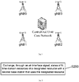
- Fig. 1 is an architecture schematic diagram of a communication system according to an embodiment of the present application.
- the communication system of the present application may include, for example, a centralized unit (CU) or core network, and a base station cluster (for example, including a plurality of base stations such as gNB0, gNB 1, gNB2, and gNB3).
- CU centralized unit
- base station cluster for example, including a plurality of base stations such as gNB0, gNB 1, gNB2, and gNB3.
- Each base station in the base station cluster may join or exit an inter-base station (gNB) communication mode to realize communication with the CU or the core network or other base stations.
- gNB inter-base station
- Mutual information exchange and data transmission between the centralized unit (CU) or the core network and the base station cluster, and between the base stations in the base station cluster may be realized through an air interface signal.
- a designated resource for communication between the base stations may be divided into N parts by a time-division multiplexing (TDM) technique to obtain N time-domain resources, and sizes of the N time-domain resources may be the same or different, or not completely the same.
- TDM time-division multiplexing
- Each time-domain resource may have a guard period GP to provide time synchronization difference and a time interval required for receiving and transmitting conversion.
- Each base station may receive key parameters of the air interface signal for inter-gNB communication from the centralized unit (CU) or the core network, such as a frequency domain resource location, a time-division multiplexing period P, inter-gNB TDM resource division, a frequency synchronization reference gNB0, a guard period on each resource and other basic configuration information, and realize time-frequency domain synchronization between the base stations, determines division of the N resources, and so on.
- the time synchronization of the gNBs may adopt an absolute synchronization method, such as GPS synchronization; and the frequency synchronization may, for example, use a reference base station gNB0 to complete the air interface time-frequency synchronization between the gNBs.
- Each gNB may receive the air interface signal for inter-gNB communication on the N time-domain resources, and determine respective states of the N time-domain resources based on the received air interface signal, such as which time-domain resources of the N time-domain resources are in an idle state, which time-domain resources are in an occupied state, which time-domain resources have a resource collision, and so on.
- Each gNB should at least receive the air interface signal transmit by the reference base station gNB0, so as to realize the time-frequency domain synchronization between the base stations, and know division of the N time-domain resources, and so on.
- Each gNB may select an idle resource from the time-domain resources determined to be idle among the N time-domain resources (for example, it may be selected in the order of priority or randomly, which is not limited in the present application), for example, an idle time-domain resource R1 is selected for transmitting the air interface signal.
- Each gNB may receive the air interface signal(s) on other N-1 time-domain resources other than the time-domain resource occupied by itself (that is, the selected time-domain resource R1 for transmitting the air interface signal), so as to know the respective states of the N time-domain resources.
- the air interface signal transmitted by each gNB may include the respective states, detected out by the gNB itself, of the N time-domain resources, such as an idle state, an occupied state, or a resource collision state.
- the above air interface signal may also carry interference coordination information, for example, the gNB is communicating with UE C (location information) on a resource B, and the transmission power is D.
- the above air interface signal may also include real business data.
- a gNB does not need to transmit the air interface signal (for example, exits the inter-base station communication mode), it may also be an exit indication signal transmitted by the gNB.
- each gNB itself may detect the states of the N time-domain resources in the following manner (for the convenience of description, a time-division multiplexing period of the designated resource is named a detection period): for each time-domain resource, if the air interface signal is not received on the time-domain resource within at least one detection period, the time-domain resource is in an idle state; if the air interface signal transmitted by one second base station is detected out on the time-domain resource within one detection period, the time-domain resource is in an occupied state; and if the air interface signals transmitted by at least two second base stations are detected out on the time-domain resource within one detection period, the time-domain resource is in a resource collision state.
- a resource collision occurs. If any other gNB detects that a resource collision occurs on a certain time-domain resource, the occurrence of the collision is indicated in a predetermined manner. For example, when a plurality of gNBs have a collision, other gNBs that have no collision may transmit the air interface signal on the time-domain resources occupied by themselves, and the air interface signal carries an indication signal indicating that a resource collision occurs on a certain time-domain resource. When the gNB that receives the indication signal determines that the time-domain resource occupied by itself has a collision, the gNB exits the time-domain resource and searches for an idle resource again.
- the base stations gNB1, gNB2, and gNB3 have all entered the inter-gNB communication mode, the base stations gNB2 and gNB3 both use a time-domain resource R2 to transmit air interface signals, and the gNB 1 receives the air interface signals of the base stations gNB2 and gNB3 on the time-domain resource R2, so the gNB 1 judges that the base stations gNB2 and gNB3 have a resource collision on the time-domain resource R2.
- the base stations gNB2 and gNB3 In the air interface signal transmitted by the gNB 1 on the time-domain resource R1, it indicates that the base stations gNB2 and gNB3 have a resource collision, so that after receiving the air interface signal, the base stations gNB2 and gNB3 may know that a resource collision occurs, so they exit the time-domain resource, and continue to search for other idle resources for transmitting the air interface signals.
- the gNB may also transmit the exit indication signal, so that other base stations can know the respective states of the N time-domain resources in time.
- the resource for communication between the base stations is divided into N parts in a TDM mode.
- Each gNB may select one idle resource to transmit the air interface signal to other gNBs, and receive the air interface signals transmitted by other gNBs on other N-1 time-domain resources, and the air interface signal used for interaction may include the respective states, detected by the gNBs, of the N time-domain resources, for example, including being occupied, being idle, collision, etc., to achieve information exchange and data transmission between the base stations.
- the states of the N time-domain resources are exchanged, so the occurrence of resource collisions is reduced as much as possible, or the resource collisions can be quickly discovered and solved after occurring, thereby ensuring the time latency requirement and reliability of the communication system.
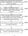
- Fig. 2 is a schematic flowchart of a method for communication according to an embodiment of the present application.
- the method for communication may be applied in the base stations gNBs as described above.
- the base stations are divided into a first base station, a second base station, and a reference base station. It should be understood that in the embodiments of the present application, the first base station, the second base station, or the reference base station may all be base stations with the same configuration or functions.
- step S200 through air interface signals, respective states of N time-domain resources of a designated resource are exchanged with the second base station that uses the designated resource.
- the above designated resource may be a resource for communication between the base stations, such as a frequency domain resource.
- the designated resource may be divided into N parts in a time-division multiplexing (TDM) mode to obtain N time-domain resources.
- TDM time-division multiplexing
- N ⁇ 1 N is a positive integer.
- a state of each time-domain resource may be one of an occupied state, an idle state, or a resource collision state.
- the exchanging, through the air interface signal, the states of the N time-domain resources of the designated resource with the second base station that uses the designated resource may include: the air interface signal is received on a time-domain resource that is not occupied by the first base station in the designated resource, the air interface signal is transmitted by at least one second base station and configured to indicate states, detected out by the second base station, of the N time-domain resources; and the respective states of the N time-domain resources are determined based on the received air interface signal.
- the exchanging, through the air interface signal, the states of the N time-domain resources of the designated resource with the second base station that uses the designated resource may further include: an idle resource is selected from the N time-domain resources according to the states of the N time-domain resources carried in the received air interface signal; and the air interface signal is transmitted by using the selected idle resource, and the transmitted air interface signal is configured to indicate states, detected out by the first base station, of the N time-domain resources.
- the first base station may detect the states of the N time-domain resources in the following manner: for each time-domain resource, if the air interface signal is not received on the time-domain resource within at least one detection period, the time-domain resource is in an idle state; if the air interface signal transmitted by one second base station is detected out on the time-domain resource within one detection period, the time-domain resource is in an occupied state; and if the air interface signals transmitted by at least two second base stations are detected out on the time-domain resource within one detection period, the time-domain resource is in a resource collision state.
- the detection period is a time-division multiplexing period of the designated resource.
- the method further includes: if the received air interface signal indicates that the time-domain resource occupied by the first base station has a resource collision, an idle resource is reselected from the N time-domain resources to transmit the air interface signal by using the reselected idle resource.
- the air interface signal may also include target data.
- the target data may be interference coordination information or business data, so as to realize information exchange and data transmission between the base stations.
- Fig. 3 is a schematic flowchart of a method for communication according to an embodiment of the present application.
- a first base station is used as a described object to describe the method for communication implemented by the base station in the present application.
- the first/second base station or the following reference base station may all be used as signal transmitters to transmit air interface signals outwards, and may also be used as target receivers to receive air interface signals transmitted by other base stations. In the entire range where M base stations cover, one base station transmits an air interface signal, and the other M-1 base stations may be the target receivers of the air interface signal.
- the order of whether the first/second base station receives the air interface signal first or transmits the air interface signal first is not fixed.
- the first base station may receive key parameters of the air interface signal for the inter-gNB communication from a CU or core network, such as a frequency domain resource location, a time-division multiplexing period P, inter-gNB TDM resource division, frequency synchronization reference gNB0, a guard period on each resource and other basic configuration information.
- step S302 time-frequency domain synchronization between the base stations is realized, division of N time-domain resources is determined, and so on.
- the time synchronization of the gNB1 may adopt an absolute synchronization manner, such as GPS synchronization; and the frequency synchronization may use a reference base station gNB0 to complete the air interface time-frequency synchronization between the gNBs.
- the first base station may receive the air interface signal(s) of the inter-gNB communication on the N time-domain resources, and judge respective states of the N time-domain resources. That is, the first base station may detect the states of the N time-domain resources in the following manner: for each time-domain resource: if the air interface signal is not received on the time-domain resource within at least one detection period, the time-domain resource is in an idle state; if the air interface signal transmitted by one second base station is detected out on the time-domain resource within one detection period, the time-domain resource is in an occupied state; and if the air interface signals transmitted by at least two second base stations are detected out on the time-domain resource within one detection period, the time-domain resource is in a resource collision state.
- the detection period is a time-division multiplexing period of a designated resource.
- the first base station (gNB1) may receive the air interface signal(s) of the inter-gNB communication on the N time-domain resources, and demodulate the respective states of the N time-domain resources. That is, the first base station may obtain the respective states of the N time-domain resources provided by each second base station by demodulating the air interface signal, transmitted by each second base station, of the inter-gNB communication, and through a certain algorithm, for example, that the minority obeys the majority, the final respective states of the N time-domain resources are obtained.
- the first base station (gNB 1) may select a time-domain resource (in order of priority or randomly) in the idle time-domain resources, for example, a time-domain resource R1, for transmitting an air interface signal.
- the transmitted air interface signal may include the respective states, detected by the gNB 1 in S303, of the N time-domain resources, and may also include other information for interaction, such as interference coordination information or business data.
- the first base station may perform air interface signal demodulation on other N-1 time-domain resources. If the air interface signal received by the gNB 1 indicates that the time-domain resource occupied by the gNB 1 has a resource collision, an idle resource is reselected from the N time-domain resources, and the air interface signal is transmitted by using the reselected idle resource.
- the air interface signal transmitted by the first base station (gNB1) may include an indication signal transmitted by the gNB1 to exit communication between the base stations. After receiving the exit indication signal, other base stations may know that the gNB1 has exited communication between the base stations.
- the first base station may join or exit communication between the base stations, and when communicating, mutually notify the respective states of the N time-domain resources of the same communication resource by different base stations through the air interface signal, so occurrence of resource collisions is avoided as much as possible.
- the resource collisions may be quickly discovered and solved quickly, thereby ensuring the time latency requirement and reliability of the entire communication system.
- the steps of the above method are only an exemplary description of the method for communication between the base stations of the present application by using the first base station as the described object, and the execution order of the steps is not fixed.
- other base stations for example, second base stations gNB2, gNB3, etc.
- communication and information exchange with other base stations may also be implemented through the steps of the above method, which will not be repeated here.
- embodiments of the present application further provide a base station.
- the base station may implement the method for communication described above in the present application.
- the base station may be the above first base station, or the second base station, or the reference base station.
- the first base station is used as a described object for description.
- Fig. 4 is a schematic structural diagram of a base station according to an embodiment of the present application.
- the first base station of the present application may include a processor 401, a memory 402, a transceiver 403 and a bus interface 404.
- the processor 401 is responsible for managing a bus architecture and general processing, and the memory 402 may store data used by the processor 401 in performing operations.
- the transceiver 403 is configured to receive and transmit data under the control of the processor 401.
- the bus architecture may include any number of interconnected buses and bridges, and is linked by various circuits of one or more processors represented by the processor 401 and the memory represented by the memory 402.
- the bus architecture may also link various other circuits such as peripheral devices, voltage regulators, power management circuits, and the like, which are well known in the art, and therefore, it will not be described further herein.
- the bus interface provides an interface.
- the processor 401 is responsible for managing the bus architecture and general processing, and the memory 402 may store the data used by the processor 401 in performing operations.
- the processes disclosed according to the embodiments of the present disclosure may be implemented in or by the processor 401.
- the steps of a signal processing flow may be performed by an integrated logic circuit in hardware or instructions in software in the processor 401.
- the processor 401 may be a general processor, a digital signal processor, a specific integrated circuit, a field programmable gate array or other programmable logic device, a discrete gate or transistor logic device, and a discrete hardware component, which may implement or perform the methods, steps, and logic block diagrams disclosed in the embodiments herein.
- the general processor may be a microprocessor, any conventional processor, etc.
- the steps of the method disclosed in connection with the embodiments of the present disclosure may be embodied directly in hardware processor execution or in a combination of hardware and software modules in the processor.
- the software module may be located in a random access memory, flash memory, read only memory, programmable read only memory, or electrically erasable programmable memory, register, or other storage media as is well known in the art.
- the storage medium is located in the memory 402, and the processor 401 reads the information in the memory 402 and completes the steps of the signal processing flow in combination with the hardware thereof.
- the processor 401 is configured to read a computer instruction in the memory 402 and execute the following process.
- N ⁇ 1 the designated resource is a resource for communication between base stations, and the N time-domain resources are obtained by means of division on the basis of a time-division multiplexing (TDM) technique.
- TDM time-division multiplexing
- a state of each time-domain resource is one of being occupied, being idle, or resource collision.
- the transceiver 403 may be configured to: receive the air interface signal on a time-domain resource that is not occupied by the first base station in the designated resource, and the air interface signal is transmitted by at least one second base station and configured to indicate states, detected out by the second base station, of the N time-domain resources; and the processor 401 may be configured to: based on the received air interface signal, determine the respective states of the N time-domain resources.
- the processor 401 is further configured to: select an idle resource from the N time-domain resources according to the state of each time-domain resource carried in the received air interface signal; and the transceiver is configured to: transmit the air interface signal by using the selected idle resource, and the transmitted air interface signal is configured to indicate states, detected out by the first base station, of the N time-domain resources.
- the processor 401 is configured to detect the states of the N time-domain resources in the following manner: for each time-domain resource: if the air interface signal is not received on the time-domain resource within at least one detection period, the time-domain resource is in an idle state; the detection period is a time-division multiplexing period of the designated resource; if the air interface signal transmitted by one second base station is detected out on the time-domain resource within one detection period, the time-domain resource is in an occupied state; and if the air interface signals transmitted by at least two second base stations are detected out on the time-domain resource within one detection period, the time-domain resource is in a resource collision state.
- the processor 401 is further configured to: if the received air interface signal indicates that the time-domain resource occupied by the first base station has a resource collision, reselect an idle resource from the N time-domain resources to transmit the air interface signal by using the reselected idle resource.
- sizes of the N time-domain resources are the same or not completely the same.
- the base station may be a base station in the method in the embodiments of the present application, and the principle of the base station to solve the problem is the same as the method, the implementation of the base station may refer to the implementation of the method, and the repetition will not be repeated.
- embodiments of the present application further provide a device for communication between base stations, and the device for communication may implement the method for communication described above in the present application.
- the device for communication may be the above first base station, or the second base station.
- the first base station is applied for description.
- Fig. 5 is a schematic structural diagram of a device for communication according to an embodiment of the present application.
- the device for communication 500 of the present application may include, for example, a communication module 510.
- the communication module may be configured to exchange, by means of an air interface signal, respective states of N time-domain resources of a designated resource with a second base station that uses the designated resource.
- N ⁇ 1 the designated resource is a resource for communication between the base stations, and the N time-domain resources are obtained by means of division on the basis of a time-division multiplexing (TDM) technique.
- TDM time-division multiplexing
- a state of each time-domain resource is one of being occupied, being idle, or resource collision.
- the communication module 510 may include:
- the communication module 510 may further include:
- the state determining module 512 may detect the states of the N time-domain resources in the following manner: for each time-domain resource: if the air interface signal is not received on the time-domain resource within at least one detection period, the time-domain resource is in an idle state; if the air interface signal transmitted by one second base station is detected out on the time-domain resource within one detection period, the time-domain resource is in an occupied state; and if the air interface signals transmitted by at least two second base stations are detected out on the time-domain resource within one detection period, the time-domain resource is in a resource collision state.
- the detection period is a time-division multiplexing period of the designated resource.
- the resource selecting module 513 may be further configured to: if the air interface signal received by the signal receiving module indicates that the time-domain resource occupied by the first base station has a resource collision, reselect an idle resource from the N time-domain resources to transmit the air interface signal by using the reselected idle resource.
- sizes of the N time-domain resources are the same or not completely the same.
- Embodiments of the present application further provide a computer readable non-transitory storage medium, including a computer program, and when the computer program runs on a computer, the computer program is configured to make the computer execute the step of determining a target access cell in the above embodiments of the present application.
- each block of the block diagrams and/or flowcharts, and combinations of blocks in the block diagrams and/or flowcharts may be implemented by computer program instructions.
- These computer program instructions may be provided to a processor of a general purpose computer, or special purpose computer, and/or other programmable data processing devices to produce a machine, such that the instructions, which execute via the processor of the computer or other programmable data processing devices, produce a method for implementing the functions/actions specified in the blocks of the block diagrams and/or the flowcharts.
- the present application may be implemented by hardware and/or software (including firmware, resident software, microcode, etc.).
- the present application may take a form of a computer program product on a computer-usable or computer-readable storage medium, which has a computer-usable or computer-readable program code implemented in the medium for use by or in combination with an instruction execution system.
- the computer-usable or computer-readable medium may be any medium that may contain, store, communicate, transmit, or convey a program for use by the instruction execution system, apparatus, or device, or in combination with the instruction execution system, apparatus, or device.
Landscapes
- Engineering & Computer Science (AREA)
- Computer Networks & Wireless Communication (AREA)
- Signal Processing (AREA)
- Mobile Radio Communication Systems (AREA)
Applications Claiming Priority (2)
| Application Number | Priority Date | Filing Date | Title |
|---|---|---|---|
| CN201910936226.5A CN112584429B (zh) | 2019-09-29 | 2019-09-29 | 基站、基站之间的通信方法、装置及存储介质 |
| PCT/CN2020/091121 WO2021057048A1 (zh) | 2019-09-29 | 2020-05-19 | 基站、基站之间的通信方法、装置及存储介质 |
Publications (2)
| Publication Number | Publication Date |
|---|---|
| EP4037372A1 true EP4037372A1 (de) | 2022-08-03 |
| EP4037372A4 EP4037372A4 (de) | 2022-10-26 |
Family
ID=75111137
Family Applications (1)
| Application Number | Title | Priority Date | Filing Date |
|---|---|---|---|
| EP20868601.4A Pending EP4037372A4 (de) | 2019-09-29 | 2020-05-19 | Basisstationen, verfahren und vorrichtung zur kommunikation zwischen basisstationen und speichermedium |
Country Status (4)
| Country | Link |
|---|---|
| US (1) | US12273899B2 (de) |
| EP (1) | EP4037372A4 (de) |
| CN (1) | CN112584429B (de) |
| WO (1) | WO2021057048A1 (de) |
Family Cites Families (14)
| Publication number | Priority date | Publication date | Assignee | Title |
|---|---|---|---|---|
| GB2458258A (en) * | 2008-02-04 | 2009-09-16 | Nec Corp | Method of controlling base station loading in a mobile communication system |
| CN103051412B (zh) * | 2011-10-14 | 2016-03-09 | 华为技术有限公司 | 小区控制方法及系统 |
| ES2566794T3 (es) * | 2012-04-12 | 2016-04-15 | Telefónica S.A. | Un método y sistema para comunicación en redes LTE |
| EP2848029A1 (de) | 2012-05-09 | 2015-03-18 | Telefonaktiebolaget LM Ericsson (Publ) | Funkbasisstation |
| US9380466B2 (en) * | 2013-02-07 | 2016-06-28 | Commscope Technologies Llc | Radio access networks |
| US9854457B2 (en) * | 2013-04-03 | 2017-12-26 | Qualcomm Incorporated | Management of communications with multiple access points based on inter-access point communications |
| US9402268B2 (en) * | 2013-08-02 | 2016-07-26 | Samsung Electronics Co., Ltd. | Transmission and scheduling schemes for wireless fronthaul |
| US20170005770A1 (en) * | 2013-12-26 | 2017-01-05 | Sharp Kabushiki Kaisha | Terminal device, base station device, and communication method |
| CN104812050B (zh) * | 2014-01-24 | 2019-11-15 | 中兴通讯股份有限公司 | 一种实现空口同步的方法、小区和系统 |
| US20170105187A1 (en) * | 2015-03-31 | 2017-04-13 | Telefonaktiebolaget Lm Ericsson (Publ) | Accurate Over the Air Synchronization |
| CN108737010B (zh) * | 2017-04-19 | 2024-04-30 | 中兴通讯股份有限公司 | 一种信息交互的方法及装置 |
| CN109219063B (zh) * | 2017-06-29 | 2022-02-11 | 中国移动通信有限公司研究院 | 一种基站间的通信方法、装置及基站 |
| CN110167186B (zh) * | 2018-02-13 | 2020-06-30 | 上海朗帛通信技术有限公司 | 一种用于无线通信的通信节点中的方法和装置 |
| WO2021127989A1 (zh) * | 2019-12-24 | 2021-07-01 | Oppo广东移动通信有限公司 | 信息传输方法、装置、电子设备和存储介质 |
-
2019
- 2019-09-29 CN CN201910936226.5A patent/CN112584429B/zh active Active
-
2020
- 2020-05-19 WO PCT/CN2020/091121 patent/WO2021057048A1/zh not_active Ceased
- 2020-05-19 US US17/639,587 patent/US12273899B2/en active Active
- 2020-05-19 EP EP20868601.4A patent/EP4037372A4/de active Pending
Also Published As
| Publication number | Publication date |
|---|---|
| CN112584429B (zh) | 2022-05-27 |
| US20220303980A1 (en) | 2022-09-22 |
| CN112584429A (zh) | 2021-03-30 |
| WO2021057048A1 (zh) | 2021-04-01 |
| US12273899B2 (en) | 2025-04-08 |
| EP4037372A4 (de) | 2022-10-26 |
Similar Documents
| Publication | Publication Date | Title |
|---|---|---|
| EP3796576B1 (de) | Signalhörverfahren, zugehörige vorrichtung, computerlesbare medien und system | |
| RU2503153C2 (ru) | Устройство и способ предотвращения помех в смешанной среде, включающей устройства, работающие в режиме связи "устройство-устройство", и устройства сотовой связи | |
| CN107026723B (zh) | 一种传输上行控制信息的方法和设备 | |
| EP2757844B1 (de) | Verfahren und vorrichtung zur zuweisung von mehrfunk-remote-einheiten-co-zellen-ressourcen | |
| EP3595371A1 (de) | Verfahren zur signalübertragung und vorrichtung | |
| WO2020243966A1 (en) | Methods for communication, devices, and computer readable medium | |
| US20200170004A1 (en) | Method and device for transmitting uplink control information | |
| US20130022010A1 (en) | Method and Apparatus for Managing Inter-Cell Interference for Device-to-Device Communications | |
| EP3099095B1 (de) | Verfahren und vorrichtung zur bestimmung und erfassung von funkressourcen | |
| US20200037277A1 (en) | Downlink synchronization signal sending method and receiving method and device | |
| US20240292462A1 (en) | Method, device and computer readable medium for communications | |
| EP3435720A1 (de) | Verfahren zum konfigurieren und empfangen von planungssignalisierung und entsprechende vorrichtungen | |
| WO2018082575A1 (zh) | 一种下行控制信号的传输方法及装置 | |
| CN113300802A (zh) | 传输方法及设备 | |
| JP2021521740A (ja) | 測定制限方法及び装置 | |
| WO2021258398A1 (en) | Method for communications, terminal device, and computer readable medium | |
| US11895683B2 (en) | Information transmission method, network device, and terminal device | |
| US20250159537A1 (en) | Measurement method and terminal | |
| WO2020143053A1 (en) | Method, device and computer readable medium for measuring sidelink received signal strength | |
| EP3142438A1 (de) | Verfahren für vorrichtungsübergreifende kommunikationen, basisstation und benutzergerät | |
| US12273899B2 (en) | Base stations, method and device for communication between base stations, and storage medium | |
| US20230071462A1 (en) | Control information communication method and device | |
| EP3965507B1 (de) | Endgeräteplanungsverfahren, vorrichtung und speichermedium | |
| WO2019075876A1 (zh) | 资源调度方法和终端设备 | |
| CN117979427A (zh) | 一种通信方法、装置及存储介质 |
Legal Events
| Date | Code | Title | Description |
|---|---|---|---|
| STAA | Information on the status of an ep patent application or granted ep patent |
Free format text: STATUS: THE INTERNATIONAL PUBLICATION HAS BEEN MADE |
|
| PUAI | Public reference made under article 153(3) epc to a published international application that has entered the european phase |
Free format text: ORIGINAL CODE: 0009012 |
|
| STAA | Information on the status of an ep patent application or granted ep patent |
Free format text: STATUS: REQUEST FOR EXAMINATION WAS MADE |
|
| 17P | Request for examination filed |
Effective date: 20220329 |
|
| AK | Designated contracting states |
Kind code of ref document: A1 Designated state(s): AL AT BE BG CH CY CZ DE DK EE ES FI FR GB GR HR HU IE IS IT LI LT LU LV MC MK MT NL NO PL PT RO RS SE SI SK SM TR |
|
| A4 | Supplementary search report drawn up and despatched |
Effective date: 20220922 |
|
| RIC1 | Information provided on ipc code assigned before grant |
Ipc: H04W 72/04 20090101ALN20220916BHEP Ipc: H04W 28/04 20090101ALI20220916BHEP Ipc: H04W 28/02 20090101AFI20220916BHEP |
|
| DAV | Request for validation of the european patent (deleted) | ||
| DAX | Request for extension of the european patent (deleted) | ||
| STAA | Information on the status of an ep patent application or granted ep patent |
Free format text: STATUS: EXAMINATION IS IN PROGRESS |
|
| 17Q | First examination report despatched |
Effective date: 20241219 |