EP4037318A1 - Verfahren, vorrichtung und apparat für die kodierung und dekodierung - Google Patents
Verfahren, vorrichtung und apparat für die kodierung und dekodierung Download PDFInfo
- Publication number
- EP4037318A1 EP4037318A1 EP20869844.9A EP20869844A EP4037318A1 EP 4037318 A1 EP4037318 A1 EP 4037318A1 EP 20869844 A EP20869844 A EP 20869844A EP 4037318 A1 EP4037318 A1 EP 4037318A1
- Authority
- EP
- European Patent Office
- Prior art keywords
- block
- sub
- pixel
- current image
- pixel points
- Prior art date
- Legal status (The legal status is an assumption and is not a legal conclusion. Google has not performed a legal analysis and makes no representation as to the accuracy of the status listed.)
- Pending
Links
Images


Classifications
-
- H—ELECTRICITY
- H04—ELECTRIC COMMUNICATION TECHNIQUE
- H04N—PICTORIAL COMMUNICATION, e.g. TELEVISION
- H04N19/00—Methods or arrangements for coding, decoding, compressing or decompressing digital video signals
- H04N19/10—Methods or arrangements for coding, decoding, compressing or decompressing digital video signals using adaptive coding
- H04N19/134—Methods or arrangements for coding, decoding, compressing or decompressing digital video signals using adaptive coding characterised by the element, parameter or criterion affecting or controlling the adaptive coding
- H04N19/157—Assigned coding mode, i.e. the coding mode being predefined or preselected to be further used for selection of another element or parameter
- H04N19/159—Prediction type, e.g. intra-frame, inter-frame or bidirectional frame prediction
-
- H—ELECTRICITY
- H04—ELECTRIC COMMUNICATION TECHNIQUE
- H04N—PICTORIAL COMMUNICATION, e.g. TELEVISION
- H04N19/00—Methods or arrangements for coding, decoding, compressing or decompressing digital video signals
- H04N19/10—Methods or arrangements for coding, decoding, compressing or decompressing digital video signals using adaptive coding
- H04N19/102—Methods or arrangements for coding, decoding, compressing or decompressing digital video signals using adaptive coding characterised by the element, parameter or selection affected or controlled by the adaptive coding
- H04N19/103—Selection of coding mode or of prediction mode
- H04N19/105—Selection of the reference unit for prediction within a chosen coding or prediction mode, e.g. adaptive choice of position and number of pixels used for prediction
-
- H—ELECTRICITY
- H04—ELECTRIC COMMUNICATION TECHNIQUE
- H04N—PICTORIAL COMMUNICATION, e.g. TELEVISION
- H04N19/00—Methods or arrangements for coding, decoding, compressing or decompressing digital video signals
- H04N19/10—Methods or arrangements for coding, decoding, compressing or decompressing digital video signals using adaptive coding
- H04N19/102—Methods or arrangements for coding, decoding, compressing or decompressing digital video signals using adaptive coding characterised by the element, parameter or selection affected or controlled by the adaptive coding
- H04N19/103—Selection of coding mode or of prediction mode
- H04N19/11—Selection of coding mode or of prediction mode among a plurality of spatial predictive coding modes
-
- H—ELECTRICITY
- H04—ELECTRIC COMMUNICATION TECHNIQUE
- H04N—PICTORIAL COMMUNICATION, e.g. TELEVISION
- H04N19/00—Methods or arrangements for coding, decoding, compressing or decompressing digital video signals
- H04N19/10—Methods or arrangements for coding, decoding, compressing or decompressing digital video signals using adaptive coding
- H04N19/102—Methods or arrangements for coding, decoding, compressing or decompressing digital video signals using adaptive coding characterised by the element, parameter or selection affected or controlled by the adaptive coding
- H04N19/119—Adaptive subdivision aspects, e.g. subdivision of a picture into rectangular or non-rectangular coding blocks
-
- H—ELECTRICITY
- H04—ELECTRIC COMMUNICATION TECHNIQUE
- H04N—PICTORIAL COMMUNICATION, e.g. TELEVISION
- H04N19/00—Methods or arrangements for coding, decoding, compressing or decompressing digital video signals
- H04N19/10—Methods or arrangements for coding, decoding, compressing or decompressing digital video signals using adaptive coding
- H04N19/134—Methods or arrangements for coding, decoding, compressing or decompressing digital video signals using adaptive coding characterised by the element, parameter or criterion affecting or controlling the adaptive coding
- H04N19/136—Incoming video signal characteristics or properties
- H04N19/137—Motion inside a coding unit, e.g. average field, frame or block difference
- H04N19/139—Analysis of motion vectors, e.g. their magnitude, direction, variance or reliability
-
- H—ELECTRICITY
- H04—ELECTRIC COMMUNICATION TECHNIQUE
- H04N—PICTORIAL COMMUNICATION, e.g. TELEVISION
- H04N19/00—Methods or arrangements for coding, decoding, compressing or decompressing digital video signals
- H04N19/10—Methods or arrangements for coding, decoding, compressing or decompressing digital video signals using adaptive coding
- H04N19/169—Methods or arrangements for coding, decoding, compressing or decompressing digital video signals using adaptive coding characterised by the coding unit, i.e. the structural portion or semantic portion of the video signal being the object or the subject of the adaptive coding
- H04N19/17—Methods or arrangements for coding, decoding, compressing or decompressing digital video signals using adaptive coding characterised by the coding unit, i.e. the structural portion or semantic portion of the video signal being the object or the subject of the adaptive coding the unit being an image region, e.g. an object
- H04N19/176—Methods or arrangements for coding, decoding, compressing or decompressing digital video signals using adaptive coding characterised by the coding unit, i.e. the structural portion or semantic portion of the video signal being the object or the subject of the adaptive coding the unit being an image region, e.g. an object the region being a block, e.g. a macroblock
-
- H—ELECTRICITY
- H04—ELECTRIC COMMUNICATION TECHNIQUE
- H04N—PICTORIAL COMMUNICATION, e.g. TELEVISION
- H04N19/00—Methods or arrangements for coding, decoding, compressing or decompressing digital video signals
- H04N19/10—Methods or arrangements for coding, decoding, compressing or decompressing digital video signals using adaptive coding
- H04N19/169—Methods or arrangements for coding, decoding, compressing or decompressing digital video signals using adaptive coding characterised by the coding unit, i.e. the structural portion or semantic portion of the video signal being the object or the subject of the adaptive coding
- H04N19/182—Methods or arrangements for coding, decoding, compressing or decompressing digital video signals using adaptive coding characterised by the coding unit, i.e. the structural portion or semantic portion of the video signal being the object or the subject of the adaptive coding the unit being a pixel
-
- H—ELECTRICITY
- H04—ELECTRIC COMMUNICATION TECHNIQUE
- H04N—PICTORIAL COMMUNICATION, e.g. TELEVISION
- H04N19/00—Methods or arrangements for coding, decoding, compressing or decompressing digital video signals
- H04N19/10—Methods or arrangements for coding, decoding, compressing or decompressing digital video signals using adaptive coding
- H04N19/189—Methods or arrangements for coding, decoding, compressing or decompressing digital video signals using adaptive coding characterised by the adaptation method, adaptation tool or adaptation type used for the adaptive coding
-
- H—ELECTRICITY
- H04—ELECTRIC COMMUNICATION TECHNIQUE
- H04N—PICTORIAL COMMUNICATION, e.g. TELEVISION
- H04N19/00—Methods or arrangements for coding, decoding, compressing or decompressing digital video signals
- H04N19/44—Decoders specially adapted therefor, e.g. video decoders which are asymmetric with respect to the encoder
-
- H—ELECTRICITY
- H04—ELECTRIC COMMUNICATION TECHNIQUE
- H04N—PICTORIAL COMMUNICATION, e.g. TELEVISION
- H04N19/00—Methods or arrangements for coding, decoding, compressing or decompressing digital video signals
- H04N19/50—Methods or arrangements for coding, decoding, compressing or decompressing digital video signals using predictive coding
- H04N19/503—Methods or arrangements for coding, decoding, compressing or decompressing digital video signals using predictive coding involving temporal prediction
- H04N19/51—Motion estimation or motion compensation
- H04N19/513—Processing of motion vectors
-
- H—ELECTRICITY
- H04—ELECTRIC COMMUNICATION TECHNIQUE
- H04N—PICTORIAL COMMUNICATION, e.g. TELEVISION
- H04N19/00—Methods or arrangements for coding, decoding, compressing or decompressing digital video signals
- H04N19/50—Methods or arrangements for coding, decoding, compressing or decompressing digital video signals using predictive coding
- H04N19/503—Methods or arrangements for coding, decoding, compressing or decompressing digital video signals using predictive coding involving temporal prediction
- H04N19/51—Motion estimation or motion compensation
- H04N19/527—Global motion vector estimation
-
- H—ELECTRICITY
- H04—ELECTRIC COMMUNICATION TECHNIQUE
- H04N—PICTORIAL COMMUNICATION, e.g. TELEVISION
- H04N19/00—Methods or arrangements for coding, decoding, compressing or decompressing digital video signals
- H04N19/50—Methods or arrangements for coding, decoding, compressing or decompressing digital video signals using predictive coding
- H04N19/503—Methods or arrangements for coding, decoding, compressing or decompressing digital video signals using predictive coding involving temporal prediction
- H04N19/51—Motion estimation or motion compensation
- H04N19/577—Motion compensation with bidirectional frame interpolation, i.e. using B-pictures
-
- H—ELECTRICITY
- H04—ELECTRIC COMMUNICATION TECHNIQUE
- H04N—PICTORIAL COMMUNICATION, e.g. TELEVISION
- H04N19/00—Methods or arrangements for coding, decoding, compressing or decompressing digital video signals
- H04N19/70—Methods or arrangements for coding, decoding, compressing or decompressing digital video signals characterised by syntax aspects related to video coding, e.g. related to compression standards
Definitions
- the present application relates to video encoding and decoding technologies, and in particular, to an encoding and decoding method, apparatus, and device.
- JVET Joint Video Experts Team
- the present application provides a method, an apparatus and a device for encoding and decoding.
- a method for encoding and decoding including:
- an apparatus for encoding and decoding apparatus including:
- an encoding side device including a processor and a machine-readable storage medium, in which the machine-readable storage medium stores machine-executable instructions executable by the processor, and the processor is configured to execute the machine-executable instructions to implement the following steps:
- a decoding side device including a processor and a machine-readable storage medium, in which the machine-readable storage medium stores machine-executable instructions executable by the processor, and the processor is configured to execute the machine-executable instructions to implement the following steps:
- the prediction compensation value of each pixel point of the current image block is determined based on the gradient value and the offset vector of each pixel point of the current image block, then the final prediction value of each pixel point of the current image block is determined based on the prediction value and the prediction compensation value of each pixel point of the current image block.
- the prediction compensation adjustment is no longer limited to an image block using the bidirectional prediction mode, and is not limited to an image block for which the motion vector of each sub-block is the same as the motion vector of each pixel in the corresponding sub-block, which expands application scope of prediction compensation adjustment.
- a Coding Tree Unit (CTU) is recursively divided into Coding Units (CUs) using a quadtree. Whether intra-coding or inter-coding is used is determined at a CU level of a leaf node.
- a CU may be further divided into two or four Prediction Units (PUs), and the same prediction information is used in the same PU. After residual information is obtained after the prediction is completed, a CU may be further quadtree-divided into a plurality of Transform Units (TUs). For example, a current image block in present application is a PU.
- VVC Versatile Video Coding
- a division structure mixing binary tree/ternary tree/quadtree divisions replaces the previous division mode. Distinctions between the concepts of CU, PU, and TU are removed, and a more flexible division mode for a CU is supported.
- a CU may be a division in square and/or rectangular.
- quadtree division is implemented for CTU, and then binary tree division and ternary tree division may be implemented for the quadtree divided leaf nodes.
- Fig. 1A there are five division modes for a CU, namely, quadtree division, horizontal binary tree division, vertical binary tree division, horizontal ternary tree division and vertical ternary tree division.
- CU in a CTU may be divided in one of the five division modes or any combination thereof, resulting in PUs of various shapes, such as rectangles and squares in various sizes.
- Prediction Signal a pixel value derived from an encoded or decoded pixel, and the residual is obtained from the difference between the original pixel and the prediction pixel, and then the residual transformation quantization and coefficient coding are implemented.
- an inter-frame prediction signal is a pixel value of a current image block derived from a reference picture (reconstructed pixel picture). Due to the discrete pixel positions, a final prediction signal needs to be obtained through an interpolation operation. The closer the prediction pixel is to the original pixel, the smaller the residual energy obtained from subtraction between them, and the higher the coding compression performance.
- Motion Vector in inter-frame coding, an MV represents the relative displacement between the current coding block and the optimal matching block in the reference image.
- Each block from division (which may be referred to as a sub-block) has a corresponding motion vector that is to be transmitted to a decoding side. If the MV for each sub-block, especially sub-blocks of small sizes, is encoded and transmitted, a significant amount of bits are required.
- the MV of the current block to be encoded is predicted according to MVs of adjacent encoded blocks by using spatial correlation between adjacent image blocks, and then the prediction difference is encoded. This can effectively reduce the amount of bits representing the MV.
- the MV of the current image block is generally predicted by using the MVs of the adjacent encoded blocks, and then the difference between a Motion Vector Prediction (MVP) value and the real estimated value of the Motion Vector, that is, the Motion Vector Difference (MVD), is encoded, so that the amount of encoding bits of MVs is effectively reduced.
- MVP Motion Vector Prediction
- MVP Motion Vector Prediction
- MVP Motion Vector Difference
- Motion Information since a MV indicates the relative displacement between the current image block and the optimal matching block in a certain reference image, in order to accurately obtain the information pointing to the image block, in addition to the MV information, the used reference image is to be indicated through reference image index information.
- a reference image list is typically created for a current image based on certain principles.
- the reference image index information indicates which reference image in the reference image list is used for the current image block.
- many coding techniques also support multiple reference image lists, and therefore a further index value is required to indicate which reference image list is used.
- the index value may be referred to as a reference direction.
- coding information related to motion such as MV, reference picture index, and reference direction, is collectively referred to as motion information.
- Interpolation if the current MV is a non-integer pixel, the existing pixel value cannot be directly copied from the corresponding reference picture, and has to be obtained through interpolation.
- Motion compensation a process of obtaining all prediction pixel values of the current image block through interpolation (or copying).
- Temporal Motion Vector Prediction (TMVP) mode a mode of multiplexing motion vectors in a time domain reference picture.
- Bi-directional Optical Flow (BDOF) mode also referred to as a BIO mode, in which motion compensation value adjustment is performed based on motion compensation values of two reference pictures using an optical flow method.
- Decoder-side Motion Vector Refinement (DMVR) mode searching for a motion vector difference based on motion compensation values of two reference pictures.
- Symmetric Motion Vector Difference (SMVD) mode the motion vector difference of one direction is directly derived from the motion vector difference of the other direction without encoding in the bidirectional prediction mode.
- a motion vector difference of a certain direction can be obtained by scaling directly the motion vector difference in the direction, and the scaling factor is related to the distance from the two reference pictures to the picture to which the current image block belongs.
- the encoding and decoding method for prediction compensation adjustment described herein may be applied to an encoding device or a decoding side device.
- the image block described herein is an encoding block when the method is applied to an encoding side device; and is a decoding block when the method is applied to a decoding device.
- a schematic flowchart of an encoding and decoding method for prediction compensation adjustment according to an embodiment of the present application is shown, and as shown in Fig. 3 , the encoding and decoding method for prediction compensation adjustment may include the following steps.
- step S300 prediction values of pixel points of a current image block are determined.
- the prediction value of each pixel point of the current image block may be determined based on the motion information of the current image block.
- the current image block may be divided into a plurality of sub-blocks, and the prediction value of each pixel point in each sub-block may be determined based on the sub-block.
- the sub-blocks may be 4 ⁇ 4 sub-blocks or 8 ⁇ 8 sub-blocks.
- an 8 ⁇ 8 image block may be divided into four 4 ⁇ 4 sub-blocks, and the prediction values of pixel points in each 4 ⁇ 4 sub-block are determined respectively.
- a 16 ⁇ 16 image block may be divided into four 8 ⁇ 8 sub-blocks, and the prediction values of the pixel points in each 8 ⁇ 8 sub-block are determined respectively.
- step S310 gradient values of pixel points of the current image block is determined based on the prediction values of pixel points of the current image block.
- step S320 offset vectors of pixel points of the current image block are determined.
- gradient values of pixel points of the current image block may be determined based on the prediction values of the pixel points of the current image block.
- the offset vector of each pixel point of the current image block may be determined.
- gradient values of pixel points of the current image block may be determined first and then the offset vectors of pixel points of the current image block are determined as shown in Fig. 3 .
- the offset vectors of pixel points of the current image block may be determined first and then gradient values of pixel points of the current image block are determined.
- the gradient value and the offset vector of each pixel point of the current image block may be determined in parallel, and specific implementations thereof are not described herein repeatedly.
- prediction compensation values of pixel points of the current image block are determined based on the gradient values and the offset vectors of pixel points of the current image block.
- prediction compensation values of pixel points of the current image block can be determined.
- final prediction values of pixel point of the current image block are determined based on the prediction values and the prediction compensation values of pixel points of the current image block.
- final prediction values of pixel points of the current image block can be determined.
- prediction compensation values of pixel points of the current image block are determined based on gradient values and offset vectors of pixel points of the current image block.
- the final prediction values of pixel points of the current image block are determined based on prediction values and prediction compensation values of pixel points of the current image block.
- the prediction compensation adjustment is no longer limited to an image block using the bidirectional prediction mode, and is not limited to an image block for which the motion vector of each sub-block is the same as the motion vector of each pixel in the corresponding sub-block, which expands application scope of prediction compensation adjustment.
- the predication compensation adjustment is no longer limited to image blocks in bidirectional prediction mode. That is, the method is also applicable to image blocks in unidirectional prediction mode.
- determining the prediction value of each pixel point of the current image block in step S300 may include: determining unidirectional prediction values of pixel points of the current image.
- determining gradient values of pixel points of the current image block based on the prediction values of pixel points of the current image block may include: determining gradient values of pixel points of the current image block in the direction based on the unidirectional prediction values of pixel points of the current image block.
- determining offset vectors of pixel points of the current image block may include: determining offset vectors of pixel points of the current image block in the direction.
- determining prediction compensation values of pixel points of the current image block based on the gradient values and the offset vectors of pixel points of the current image block may include: determining prediction compensation values of pixel points of the current image block in the direction based on the gradient values and offset vectors of pixel points of the current image block in the direction.
- determining final prediction values of pixel points of the current image block based on the prediction values and the prediction compensation values of pixel points of the current image block may include: determining final prediction values of pixel points of the current image block in the direction based on the prediction values and prediction compensation values of pixel points of the current image block in the direction.
- the prediction value of a pixel point of the current image block when the prediction value of a pixel point of the current image block is to be determined, the prediction value of the pixel point of the current image block in one direction may be determined.
- a forward prediction value of a pixel point of the current image block may be determined; if the current image block uses a backward prediction mode, a backward prediction value of the pixel point of the current image block may be determined.
- Forward prediction values of pixel points of the current image block have been determined.
- forward gradient values of pixel points of the current image block may be determined based on the forward prediction values of pixel points of the current image block; on the other hand, forward offset vectors of pixel points of the current image block may be determined.
- forward prediction compensation values of pixel points of the current image block may be determined based on forward gradient values and offset vectors of pixel points of the current image block, and forward final prediction values of pixel points of the current image block may be determined based on forward prediction values and prediction compensation values of pixel points of the current image block.
- the operation in S300 of determining prediction values of pixel points of a current image block may include: determining forward prediction values and backward prediction values of pixel points of the current image block respectively.
- determining gradient values of pixel points of the current image block based on the prediction values of pixel points of the current image block may include: determining forward gradient values and backward gradient values of pixel points of the current image block based on the forward prediction values and the backward prediction values of pixel points of the current image block respectively.
- determining offset vectors of pixel points of the current image block may include: determining forward offset vectors and backward offset vectors of pixel points of the current image block respectively.
- determining prediction compensation values of pixel points of the current image block based on the gradient values and the offset vectors of pixel points of the current image block may include: determining forward prediction compensation values and backward prediction compensation values of pixel points of the current image block based on the forward gradient values, backward gradient values, forward offset vectors and backward offset vectors of pixel points of the current image block respectively.
- determining final prediction values of pixel points of the current image block based on the prediction values and the prediction compensation values of pixel points of the current image block may include: determining forward final prediction values and backward final prediction values of pixel points of the current image block based on the forward prediction values, backward prediction values, forward prediction compensation values and backward prediction compensation value of pixel points of the current image block respectively; and determining final prediction values of pixel points of the current image block based on the forward final prediction values and backward final prediction values of pixel points of the current image block.
- forward prediction values, backward prediction values, forward prediction compensation values and the backward prediction compensation values of pixel points of the current image block are determined respectively, so as to determine forward and backward final prediction values of pixel points of the current image block.
- Final prediction value of pixel points of the current image block are then determined.
- forward final prediction values or backward final prediction values of pixel points of the current image block may be determined with reference to the determination of the current image block using the unidirectional prediction mode.
- final prediction values of pixel points of the current image block may be determined based on the forward final predication values and the backward final prediction values of pixel points of the current image block.
- the forward final predication value and the backward final prediction value of each pixel point of the current image block are weighted to obtain the final prediction value of each pixel point of the current image block.
- the operation in S320 wherein determining offset vectors of pixel points of the current image block may include:
- the offset vector of any pixel point (referred to as a specified pixel point herein) in the sub-block may be determined first, and then the offset vectors of other pixel points in the sub-block are determined based on the offset vector of the specified pixel point in the sub-block.
- determining the offset vector of the specified pixel point in the sub-block may include: determining the offset vector of the specified pixel point in the sub-block based on Affine parameters and an offset of the specified pixel point from a center position of the sub-block.
- the offset vector of the specified pixel point in the sub-block may be determined based on Affine parameters and the offset of the specified pixel point in the sub-block from the center position of the sub-block.
- determining the offset vector of the specified pixel point in the sub-block based on Affine parameters and an offset of the specified pixel point from a center position of the sub-block may include:
- the first Affine parameter and the fourth Affine parameter are the same, either of which is a ratio of a first numerical value to the width of the sub-block, the second Affine parameter and the third Affine parameter are opposite, and the third Affine parameter is a ratio of a second numerical value to the width of the sub-block.
- the first Affine parameter is a ratio of the first numerical value to the width of the sub-block
- the second Affine parameter is a ratio of a third numerical value to the height of the sub-block
- the third Affine parameter is a ratio of the second numerical value to the width of the sub-block
- the fourth Affine parameter is a ratio of a fourth numerical value to the height of the sub-block.
- the first numerical value is a difference between a horizontal component of a motion vector of an upper right control point of the sub-block and a horizontal component of a motion vector of an upper left control point of the sub-block
- the second numerical value is a difference between a vertical component of the motion vector of the upper right control point of the sub-block and a vertical component of the motion vector of the upper left control point of the sub-block
- the third numerical value is a difference between a horizontal component of the motion vector of a lower left control point of the sub-block and a horizontal component of the motion vector of the upper left control point of the sub-block
- the fourth numerical value is a difference between a vertical component of the motion vector of the lower left control point of the sub-block and a vertical component of the motion vector of the upper left control point of the sub-block.
- the motion vectors of the upper left control point, the upper right control point and the lower left control point are ( v 0 x , v 0 y ), ( v 1 x , v 1 y ) and ( v 2 x , v 2 y ) respectively, the first numerical value is v 1 x - v 0 x , the second numerical value is v 1 y - v 0 y , the third numerical value is v 2 x - v 0 x , the fourth numerical value is v 2 y - v 0 y .
- ⁇ v x ( x , y ) is the horizontal component of the offset vector of the specified pixel point in the sub-block
- ⁇ v y ( x,y ) is the vertical component of the offset vector of the specified pixel point in the sub-block
- ( ⁇ x, ⁇ y) is the offset of the specified pixel point from the center position of the sub-block.
- determining offset vectors of the other pixel points in the sub-block based on the offset vector of the specified pixel point in the sub-block comprises:
- Affine motion mode is applied to the current image block.
- the offset vectors of other pixel points in the same row of the specified pixel point in the sub-block may be respectively determined based on the offset vector of the sub-block, the first Affine parameter, and the third Affine parameter.
- the offset vectors of other pixel points in the same column of the pixel point in the sub-block may be determined based on the offset vector of the pixel point, the second Affine parameter and the fourth Affine parameter.
- the horizontal component of the offset vector of the pixel point may be a sum of a horizontal component of the offset vector of the left-adjacent pixel point of the pixel point (if exist) and the first Affine parameter, or the difference between a horizontal component of the offset vector of the right-adjacent pixel point of the pixel point (if exist) and the first Affine parameter.
- the vertical component of the offset vector of the pixel point may be a sum of a vertical component of the offset vector of the left-adjacent pixel point of the pixel point (if exist) and the third Affine parameter, or a difference between a vertical component of the offset vector of the right-adjacent pixel point of the pixel point (if exist) and the third Affine parameter.
- the horizontal component of the offset vector of the pixel point may be a sum of a horizontal component of the offset vector of the above-adjacent pixel point (if exist) and the second Affine parameter, or the difference between a horizontal component of the offset vector of the below-adjacent pixel point (if exist) and the second Affine parameter.
- the vertical component of the offset vector of the pixel point may be a sum of a vertical component of the offset vector of the above-adjacent pixel point (if exist) and the fourth Affine parameter, or a difference between a vertical component of the offset vector of the below-adjacent pixel point (if exist) and the fourth Affine parameter.
- the operation in S310 of determining gradient values of pixel points of the current image block based on the prediction values of pixel points of the current image block comprises:
- pixel values of adj acent pixel points at the left and right of the pixel are required, and in determination of the vertical component of the gradient value of the pixel point, pixel values of adjacent pixel point above and below the pixel point are required.
- required pixels are missing on at least one side.
- N is a positive integer
- rows/columns of integer pixel points are respectively filled on each of the top, bottom, left and right edges of the sub-block.
- Gradient values of pixel points in the sub-block are determined based on prediction values of pixel points of the sub-block and pixel values of the filled integer pixel points.
- pixel values of the filled row/column of integer pixel points may be directly copied from near integer pixel points of the reference pixel.
- filling N row(s)/column(s) of integer pixel points on each of the top, bottom, left and right edges of the sub-block comprises:
- an equal-sized integer-pixel block (a block formed by integer pixel points) closest to the sub-block may be determined first in a reference picture.
- the closest 4 ⁇ 4 integer-pixel sub-block in the reference picture may be determined, as shown in Fig. 5A .
- the pixel values of the adjacent N rows/columns of integer-pixels points around the integer-pixel block may be used as the filling values of pixel points on the top, bottom, left and right edges of the sub-block, respectively.
- filling N row(s)/column(s) of integer pixel points on each of the top, bottom, left, and right edges of the sub-block comprises: filling respectively N row(s)/column(s) of integer pixel points that are exactly above, below, left to and right to the integer-pixel block respectively.
- a block with a width and a height increased by 2N than the original block is obtained after N row(s)/column(s) of integer pixel points on the top, bottom, left and right edges of a sub-block are filled, the corner points of each layer of pixel points in N layers of pixel points outside the block will not be used when calculating the gradient value of each pixel point in the original block based on the pixel value of each pixel point in the block.
- N rows/columns of integer pixel points on the top, bottom, left, and right edges of the sub-block N rows/columns of integer pixel points exactly above, below, left to and right to the equal-sized closest integer-pixel block in the reference picture are filled.
- filling respectively 1 row/column of integer pixels on the top, bottom, left and right edges of the sub-block comprises:
- pixel values of a pixel point at the left of the pixel point with a relative displacement of one pixel to the pixel point and a pixel value of the pixel point at the right of the pixel point with a relative displacement of one pixel to the pixel point are all integer pixel points.
- the relative displacement between the filled integer pixel point and the pixel point on the edge of the sub-block will not be one pixel (the relative displacement between the non-integer pixel point and the integer pixel point is a non-integer pixel).
- the positions of the to-be-filled integer pixel points may be selected based on whether the vertical component and the horizontal component of the sub-pixel (namely, the part except the integer pixel, if the pixel value is 5.4, the sub-pixel is 0.4) of the prediction value of the pixel point in the sub-block are greater than a half pixel (namely, 0.5 pixel).
- integer pixel points on the top and bottom edges are to be filled.
- a vertical component of the sub-pixel of the prediction value of the pixel point in the sub-block may be obtained, and the vertical component of the sub-pixel is compared with the half- pixel.
- the sub-pixel of the prediction value of the pixel point in the sub-block refers to the sub-pixel of the corresponding position in the reference picture for the prediction value of the pixel point in the sub-block.
- the vertical component of the sub-pixel is greater than a half pixel, for any pixel point on the top edge of the sub-block, compared with other integer pixel points above the pixel point, the relative displacement between the nearest integer pixel point above the pixel point and the pixel point is closest to one pixel, and therefore the above nearest integer pixel point is filled for the pixel point.
- the relative displacement between the next-nearest integer pixel point below the pixel point and the pixel point is closest to one pixel.
- the vertical component of the sub-pixel of a pixel point on the bottom edge of the sub-block is 0.8
- the relative displacement between the nearest integer pixel point below the pixel point and the pixel point is 0.2
- the relative displacement between the next-nearest integer pixel point below the pixel point and the pixel point is 1.2
- the relative displacements between other integer pixel points below the pixel point and the pixel point are all greater than 1.2
- next-nearest integer pixel point below is filled for the pixel point.
- the horizontal component of the sub-pixel of the prediction value of the pixel point may be processed according to the case where the horizontal component of the sub-pixel of the prediction value of the pixel point is greater than a half pixel, or according to the case where the horizontal component of the sub-pixel of the prediction value of the pixel point is smaller than a half pixel.
- the vertical component of the sub-pixel of the prediction value of the pixel point may be processed according to the case where the vertical component of the sub-pixel of the prediction value of the pixel point is greater than a half pixel, or according to the case where the vertical component of the sub-pixel of the prediction value of the pixel point is smaller than a half pixel.
- filling 1 row/column of integer pixel points on the top, bottom, left and right edges of the sub-block respectively includes: filling the integer pixel points in a filling region formed by the to-be-filled rows/columns on the top, bottom, left and right edges of the sub-block except for 4 corner points of the filing region.
- a block with width and height increased by 2 than the original block will be obtained after 1 row/column of integer pixel points are filled on the top, bottom, left and right edges of the sub-block. 4 corner points of the block will not be used when gradient values of pixel points in the original block are calculated based on pixel values of pixel points in the block.
- the original sub-block is 4 ⁇ 4 sub-block
- a 6 ⁇ 6 block will be obtained after filling 1 row/column of integer pixel points on the top, bottom, left and right edges of the sub-block and 4 corner points of the 6 ⁇ 6 block will not be used when gradient values of pixel points in the original 4 ⁇ 4 block are calculated.
- the integer pixel points in a filling region formed by the rows/columns filled on the upper, lower, left and right edges of the sub-block may be filled except for 4 corner points of the filling region.
- determining gradient values of pixel points in the sub-block based on prediction values of pixel points and pixel values of the filled integer pixel points of the sub-block may include: determining, for each pixel point in the sub-block, a horizontal component of a gradient value of the pixel point based on pixel values of N adjacent pixel points at the left of the pixel point and pixel values of N adjacent pixel points at the right of the pixel point, and determining a vertical component of the gradient value of the pixel point based on pixel values of N adjacent pixel points above the pixel point and pixel values of N adjacent pixel points below the pixel point.
- the horizontal component of the gradient value of the pixel point may be determined based on pixel values of pixel points at the left of the pixel point and pixel values of pixel points at the right of the pixel point, respectively, and the vertical component can be determined based on the pixel values of pixel points above the pixel point and pixel values of pixel points below the pixel point.
- pixel values of filled integer pixel points adjacent to the pixel point are required to determine the horizontal component or/and the vertical component of the gradient value of the pixel point.
- the pixel value of the above-adjacent filled integer pixel point of the pixel point are required to determine the vertical component of the gradient value of the pixel point; for a pixel point at the left edge of the sub-block, the pixel value of the left adjacent filled integer pixel point of the pixel point is required to determine the horizontal component of the gradient value of the pixel point.
- g x ( i , j ) is the horizontal component of the gradient value of the pixel point in the i-th column and j-th row in the sub-block
- g y ( i , j ) is the horizontal component of the gradient value of the pixel point in the i-th column and j-th row in the sub-block
- I ( i , j ) is the pixel value of the pixel point in the i-th column and j-th row in the sub-block.
- the pixel value of a pixel point in a sub-block is a prediction value
- the pixel value of a filled integer pixel point is an original value
- the pixel value of a pixel point in a sub-block is a prediction value
- the pixel value of a filled integer pixel point is a reconstruction value
- a condition (referred to as an enabling condition for the prediction compensation adjustment herein) that allows the prediction compensation adjustment solution according to the embodiment of the present application to be used may be set in advance.
- the method before determining gradient values of pixel points of the current image block based on the prediction values of pixel points of the current image block, the method further comprises:
- the enabling condition for the prediction compensation adjustment may include: a specified prediction mode is applied to the current image block, and in the specified prediction mode, a motion vector of a sub-block is not identical to a motion vector of any pixel point in the sub-block.
- the enabling condition for the prediction compensation adjustment may be set as: a specified prediction mode is applied to the current image block.
- whether the prediction compensation adjustment solution according to the embodiment of the present application is used may be determined based on the prediction mode of the current image block.
- the prediction compensation adjustment solution is used, that is, when the current image block uses the specified prediction mode, the prediction compensation adjustment is performed on the current image block according to the manner described in the above embodiment.
- the specified prediction mode includes an Affine motion mode.
- the enabling condition for the prediction compensation adjustment may further include: a currently predicted component is a luminance component, that is, the prediction compensation adjustment is performed on the luminance component of the image block using the specified prediction mode according to the prediction compensation adjustment solution according to the embodiment of the present application.
- the enabling condition for the prediction compensation adjustment may further include: the currently predicted component is a chrominance component, that is, the prediction compensation adjustment is performed on the chrominance component of the image block using the specified prediction mode according to the prediction compensation adjustment solution according to the embodiment of the present application.
- a schematic flowchart of an encoding and decoding method provided in an embodiment of the present application is shown, in context of a decoding process and an Affine mode.
- the encoding and decoding method may include the followings.
- step S600 prediction values of pixel points of a to-be-decoded block are determined.
- the decoding block is divided into 4 ⁇ 4 sub-blocks, and each sub-block is decoded separately.
- prediction values of pixel points in the sub-block may be determined based on the Affine mode.
- step S610 a determination is made as to whether the decoding block satisfies an enabling condition for prediction compensation adjustment, if the decoding block satisfies the condition for prediction compensation adjustment, the flow proceeds to step S620; otherwise, the current process is ended.
- the prediction compensation adjustment is not to be performed according to the prediction compensation adjustment solution provided in the embodiment of the present application.
- prediction values of pixel points of the block determined in step S600 may be determined as final prediction values of pixel points.
- the prediction compensation adjustment solution may be performed according to other strategies, and the specific implementation thereof is not limited.
- step S620 for each sub-block, gradient values of pixel points of the sub-block are determined based on prediction values of pixel points of the sub-block.
- step S630 offset vectors of pixel points of the sub-block are determined.
- gradient values of pixel points of the 4 ⁇ 4 sub-block may be determined based on the prediction values of pixel points of the 4 ⁇ 4 sub-block.
- offset vectors of pixel points of the 4 ⁇ 4 sub-block may be determined.
- prediction compensation values of pixel points of the sub-block are determined based on the gradient values and the offset vectors of pixel point of the sub-block.
- prediction compensation values of pixel points of the 4 ⁇ 4 sub-block may be determined based on the gradient values and the offset vectors of pixel points of the 4 ⁇ 4 sub-block.
- final prediction values of pixel points of the block are determined based on the prediction values and the prediction compensation values of pixel points of the to-be-decoded block.
- unidirectional prediction values and prediction compensation values of pixel points of the to-be-decoded block in the direction may be determined as described in the steps S600 to S640. Then final prediction values of pixel points of the to-be-decoded block are obtained.
- forward prediction values, backward prediction values, forward prediction compensation values and backward prediction compensation values of pixel points of the to-be-decoded block may be determined as described in the steps S600 to S640, and then final prediction values of pixel points of the to-be-decoded block are obtained.
- the enabling condition for the encoding and decoding method flow described in the steps S600 to S650 may include: an Affine motion mode is applied to the current image block.
- the enabling condition for the encoding and decoding method flow described in the steps S600 to S650 may include:
- the enabling condition for the encoding and decoding method flow described in the steps S600 to S650 may include:
- determining gradient values of pixel points of the sub-block in step S620 may include the followings.
- pixel values of the integer pixel points filled on the top, bottom, left and right edges of the 4 ⁇ 4 block may be derived from reconstructed values of adjacent integer pixel points in a reference picture.
- Gradient values of pixel points in the 4 ⁇ 4 sub-block are calculated based on pixel values of pixel points in the 6 ⁇ 6 block.
- the gradient value of the pixel point may be determined based on equations 4 and 5 (the horizontal component of the gradient value of the pixel point may be described as mm_gradx, and the vertical component of the gradient value of the pixel point may be described as mm_grady).
- 1 row/column of integer pixel points are filled on the top, bottom, left and right edges of the 4 ⁇ 4 sub-block respectively, which may include the following implementations.
- integer pixel points filled on the top, bottom, left, and right edges of the 4 ⁇ 4 sub-block may be selected based on whether the horizontal component and the vertical component of the sub-pixel of the prediction value of a pixel point in the 4 ⁇ 4 sub-block are greater than a half pixel.
- a nearest integer pixel point above the top edge of the 4 ⁇ 4 sub-block is filled, a next-nearest integer pixel point below the bottom edge of the 4 ⁇ 4 sub-block is filled, a nearest integer pixel point at the left of the left edge of the 4 ⁇ 4 sub-block is filled, and a next-nearest integer pixel point at the right of the right edge of the 4 ⁇ 4 sub-block is filled.
- a next-nearest integer pixel point above the top edge of the 4 ⁇ 4 sub-block is filled, a nearest integer pixel point below the bottom edge of the 4 ⁇ 4 sub-block is filled, a next nearest integer pixel point at the left of the left edge of the 4 ⁇ 4 sub-block is filled, and a next-nearest integer pixel point at the right of the right edge of the 4 ⁇ 4 sub-block is filled.
- a next-nearest integer pixel point above the top edge of the 4 ⁇ 4 sub-block is filled, a nearest integer pixel point below the bottom edge of the 4 ⁇ 4 sub-block is filled, a nearest integer pixel point at the left of the left edge of the 4 ⁇ 4 sub-block is filled, and a next-nearest integer pixel point at the right of the right edge of the 4 ⁇ 4 sub-block is filled.
- a next-nearest integer pixel point above the top edge of the 4 ⁇ 4 sub-block is filled, a next-nearest integer pixel point below the bottom edge of the 4 ⁇ 4 sub-block is filled, a next-nearest integer pixel point at the left of the left edge of the 4 ⁇ 4 sub-block is filled, and a nearest integer pixel point at the right of the right edge of the 4 ⁇ 4 sub-block is filled.
- a triangle is a prediction value of a pixel point of a 4 ⁇ 4 sub-block
- a circle is a reconstructed value of an integer pixel point in a reference picture
- a shaded circle is a reconstructed value of an integer pixel point in the reference picture selected for filling.
- the filling process may be performed according to the case where the horizontal component of the sub-pixel of the prediction value of the pixel point is greater than a half pixel, or according to the case where the horizontal component of the sub-pixel of the prediction value of the pixel point is smaller than a half pixel.
- the filling process may be performed according to the case where the vertical component of the sub-pixel of the prediction value of the pixel point is greater than a half pixel, or according to the case where the vertical component of the sub-pixel of the prediction value of the pixel point is smaller than a half pixel.
- the 4 corner points may not be filled. 4 points on each of top, bottom, left and right edges may be filled respectively.
- Fig. 7E is a schematic diagram showing a block with 1 row/column on top, bottom, left and right edges of the 4 ⁇ 4 sub-block are filled in case of both the horizontal component and the vertical component of the sub-pixel of the prediction value of the pixel point being greater than a half pixel.
- determining offset vectors of pixel points of the sub-block may include:
- the specified pixel point is the first pixel point.
- the offset ( ⁇ x, ⁇ y) of the first pixel point in the 4 ⁇ 4 sub-block from the center position of the 4 ⁇ 4 sub-block may be determined based on the coordinates of the first pixel point in the 4 ⁇ 4 sub-block and the coordinates of the center position of the 4 ⁇ 4 sub-block.
- Offset vectors of other pixel points in the 4 ⁇ 4 sub-block are determined based on the offset vectors of the first pixel point in the 4 ⁇ 4 sub-block.
- ⁇ v x ( w ,0) is the horizontal component of the offset vector of the pixel point in the w +1 column and 1st row in the 4 ⁇ 4 sub-block
- ⁇ v y ( w ,0) is the vertical component of the offset vector of the pixel point in the w +1 column and 1st row in the 4 ⁇ 4 sub-block
- ⁇ v x ( w , h ) is the horizontal component of the offset vector of the pixel point in the w +1 column and h +1 row in the 4 ⁇ 4 sub-block
- ⁇ v y ( w , h ) is the vertical component of the offset vector of the pixel point in the w +1 column and h +1 row in the 4 ⁇ 4 sub-block
- the offset vectors of pixel points in the sub-block may be reused by other sub-blocks in the decoding block.
- a "left shift and then right shift" may be used instead of division in calculating the Affine parameters c, d, e and f in order to ensure the precision and improve the hardware friendliness.
- c and e they may be left shifted by (MAX_CU_DEPTH- Log2[width]) bits first and then right shifted by MAX_CU_DEPTH bits; for d and f in the 6-parameter model, they may be left shifted by (MAX_CU_DEPTH-Log2[height]) bits and then right shifted by MAX_CU DEPTH bits.
- width is the width of the current image block
- height is the height of the current image block
- MAX_CU_DEPTH is the depth of the width or height of the largest image block, which is 7 by default (i.e., the width or height of the corresponding image block is 128).
- d ⁇ ⁇ v 2 x ⁇ v 0 x ⁇ ⁇ ⁇ 7 ⁇ ⁇ Log 2 height
- f ⁇ ⁇ v 2 y ⁇ v 0 y ⁇ ⁇ 7 ⁇ Log 2 height for example, ⁇ denotes a left shift.
- offset vectors of pixel points of the 4 ⁇ 4 sub-block may be magnified in determination thereof.
- offset vectors of pixel points of the 4 ⁇ 4 sub-block may be reduced by N2 times.
- N2 may be the same as N1 or may be different from N1.
- N1 is 4, then N2 may be 4, or N2 may be 2 (i.e., the finally determined offset vector is an offset vector magnified by 2 times).
- mvx is a horizontal component of an offset vector of a pixel point
- mvy is a vertical component of the offset vector of the pixel point
- >> represents a right shift
- ⁇ represents a left shift
- mvx and mvy are limited in a range [ - (1 ⁇ bdlimit), (1 ⁇ bdlimit) -1 ]; and bdlimit is empirically set.
- bitdlimit max (6, bitdepth-6), bitdpth is the bit depth, i.e., a required bit width of the luminance value, typically 10 or 8.
- bdlimit max (5, bitdepth-7).
- ⁇ I ( i , j ) is a prediction compensation value of a pixel point in the ith column and the jth row in a sub-block
- g x ( i , j ) is a horizontal component of a gradient value of the pixel point in the ith column and the jth row in the sub-block
- g y ( i , j ) is a vertical component of the gradient value of the pixel point in the ith column and the jth row in the sub-block
- ⁇ v x ( i , j ) is a horizontal component of an offset vector of a pixel point in the ith column and the jth row in the sub-block
- ⁇ v y ( i , j ) is a vertical component of the offset vector of the pixel point in the ith column and the jth row in the sub-block.
- mm_dI2 is a unidirectional prediction compensation value of a pixel point
- mm_dI3 is a final prediction value of the pixel point in the direction
- mvx is a horizontal component of an offset vector of the pixel point in the direction
- mvy is a vertical component of the offset vector of the pixel point in the direction
- mm_gradx is a horizontal component of a gradient value of the pixel point in the direction
- mm_grady is a vertical component of the gradient value of the pixel point in the direction
- mm_src is a prediction value of the pixel point in the direction
- mm_w is a weight value of the pixel point in the direction
- mm_w is 1 in the unidirectional prediction mode.
- the to-be-decoded block uses a bidirectional prediction mode, a forward prediction compensation adjustment and a backward prediction compensation adjustment are respectively implemented, and then the prediction compensation adjustment of the block is implemented.
- mm_dI02 is a forward prediction compensation value of a pixel point
- mm_dI03 is a forward final prediction value of the pixel point
- mvx0 is a horizontal component of a forward offset vector of the pixel point
- mvy0 is a vertical component of the forward offset vector of the pixel point
- mm_gradx0 is a horizontal component of a forward gradient value of the pixel point
- mm_grady0 is a vertical component of the forward gradient value of the pixel point
- mm_src0 is a forward prediction value of the pixel point
- mm_w0 is a forward weight value of the pixel point.
- mm_dI12 is a backward prediction compensation value of a pixel point
- mm_dI13 is a backward final prediction value of the pixel point
- mvx1 is a backward horizontal component of the offset vector of the pixel point
- mvy1 is a backward vertical component of the offset vector of the pixel point
- mm_gradx1 is a backward horizontal component of the gradient value of the pixel point
- mm_grady1 is a backward vertical component of the gradient value of the pixel point
- mm src1 is a backward prediction value of the pixel point
- mm_wl is a backward weight value of the pixel point.
- the weighting process (dividing the sum of the forward final prediction value and the backward final prediction value by the sum of the forward weight value and the backward weight value) is completed based on forward final prediction values and backward final prediction values of pixel points of the to-be-decoded block to obtain final prediction values of pixel points of the to-be-decoded block.
- the candidate motion vector selection method may include the following steps:
- the probability of the motion vector of the time domain reference picture being finally selected is low.
- a condition (referred to as a condition for using the time domain reference picture herein) for allowing the use of the motion vector of the time domain reference picture may be set in advance.
- whether the current image block satisfies the condition for using the time domain reference picture may be determined, i.e., the motion vector of the time domain reference picture is allowed to be used for encoding/decoding the current image block, or the motion vector of the time domain reference picture is not to be used for encoding/decoding the current image block.
- the condition for using the time domain reference picture may include: the size of the reference picture is the same as the size of a picture to which the current image block belongs.
- the probability of the motion vector of the time domain reference picture being finally selected is low when the size of the reference picture is different from the size of the picture to which the current image block belongs. Therefore, in order to improve the encoding and decoding performance, the condition for using the time domain reference picture is the size of the reference picture being the same as the size of the picture to which the current image block belongs.
- the motion vector of the time domain reference picture is allowed to be used for encoding/decoding the current image block; and when the size of the reference picture is different from the size of the picture to which the current image block belongs, the motion vector of the time domain reference picture is not to be used for encoding/decoding the current image block.
- condition for using thea time domain reference picture may further include: the reference picture is not a long-term reference picture (i.e. Long-Term Reference Picture, abbreviated as LTRP).
- LTRP Long-Term Reference Picture
- the long-term reference picture is relative to a reference picture that is closer to the picture to which the current image block belongs, and in general, the long-term reference picture is further from the picture to which the current image block belongs.
- the probability that the motion vector of the time domain reference picture is finally selected is lower when the size of the reference picture is the same as the size of the picture to which the current image block belongs but the reference picture is a long-term reference picture, therefore, the reference picture being not a long-term reference picture may be used as a condition for using the time domain reference picture.
- the motion vector of the time domain reference picture is allowed to be used for encoding/decoding the current image block; and when the size of the reference picture is different from the size of the picture to which the current image block belongs and/or the reference picture is a long-term reference picture, the motion vector of the time domain reference picture is not to be used for encoding/decoding the current image block.
- the motion vector of the time domain reference picture after allowing to use the motion vector of the time domain reference picture for encoding/decoding the current image block, it may further include:
- a condition (referred to as the condition for scaling and using the motion vector of the time domain reference picture herein) whether to allow to use the scaled motion vector of the time domain reference picture may be set in advance.
- the condition for scaling the motion vector of the time domain reference picture may include: the size of the reference picture is the same as the size of a picture to which the current image block belongs, and the reference picture is not a long-term reference picture.
- the probability of the scaled motion vector of the time domain reference picture being finally selected is low when the size of the reference picture is different from the size of the picture to which the current image block belongs, and/or the reference picture is a long-term reference picture. Therefore, the size of the reference picture being the same as the size of the picture to which the current image block belongs and the reference picture being not a long-term reference picture is used as the condition for scaling the motion vector of the time domain reference picture.
- the scaled motion vector of the time domain reference picture is allowed to be used for encoding/decoding the current image block; and when the size of the reference picture is different from the size of the picture to which the current image block belongs and/or the reference picture is a long-term reference picture, the scaled motion vector of the time domain reference picture is not allowed to be used for encoding/decoding the current image block.
- the method further includes:
- the first type of prediction mode includes modes involving time domain motion vectors, such as TMVP mode, BDOF mode, DMVR mode; and the second type of prediction mode includes modes involving scaling the time domain motion vectors, such as SMVD mode.
- the second type of prediction mode may also be allowed to be used when the condition for using the time domain reference picture is satisfied.
- the method further includes:
- the first type of prediction mode may also be refused.
- a schematic flowchart of a candidate motion vector selection method provided in an embodiment of the present application is shown, and as shown in Fig. 9 , the candidate motion vector selection method may include the following steps:
- the scaled motion vector of the time domain reference picture being finally selected is low in some specific situations. Therefore, in order to improve the encoding and decoding performance, and avoid using the scaled motion vector of the time domain reference picture as a candidate motion vector under a condition that the scaled motion vector of the time domain reference picture is not applicable, a condition (referred to as the condition for scaling the motion vector of the time domain reference picture herein) for allowing to use the scaled motion vector of the time domain reference picture may be set in advance.
- the condition for scaling the motion vector of the time domain reference picture may include: the size of the reference picture is the same as the size of a picture to which the current image block belongs, and the reference picture is not a long-term reference picture.
- the scaled motion vector of the time domain reference picture being finally selected is low when the size of the reference picture is different from the size of the picture to which the current image block belongs, and/or the reference picture is a long-term reference picture. Therefore, the size of the reference picture being the same as the size of the picture to which the current image block belongs and the reference picture being not a long-term reference picture is used as the condition for scaling the motion vector of the time domain reference picture.
- the scaled motion vector of the time domain reference picture is allowed to be used for encoding/decoding the current image block; and when the size of the reference picture is different from the size of a picture to which the current image block belongs or/and the reference picture is a long-term reference picture, the scaled motion vector of the time domain reference picture is refused to be used for encoding/decoding the current image block.
- the method further includes:
- the first type of prediction mode includes modes involving time domain motion vectors, such as TMVP mode, BDOF mode, DMVR mode, etc.; and the second type of prediction modes include modes involving scaling the time domain motion vectors, such as the SMVD mode.
- the first type of prediction mode may also be refused.
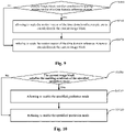
- a schematic flowchart of a prediction mode selection method according to an embodiment of the present application is shown, and as shown in Fig. 10 , the prediction mode selection method may include the following steps:
- the use of the specific prediction mode may reduce the encoding and decoding performance in some specific situations. Therefore, in order to improve the encoding and decoding performance, and avoid using the specified prediction mode as a candidate prediction mode under a condition that the specified prediction mode is not applicable, the condition (referred to as the condition for using the specified prediction mode herein) whether to allow the specified prediction mode to be used may be set in advance.
- the specified prediction mode includes the first type of prediction mode.
- the first type of prediction mode includes modes involving time domain motion vectors, such as the TMVP mode, the BDOF mode, the DMVR mode, etc.
- condition for using the specified prediction mode may include: the size of the reference picture is the same as the size of the picture to which the current image block belongs.
- the size of the reference picture being the same as the size of the picture to which the current image block belongs may be used as the condition for using the specified prediction mode. That is, when the size of the reference picture is the same as the size of the picture to which the current image block belongs, the specified prediction mode is allowed to be used; when the size of the reference picture is different from the size of the picture to which the current image block belongs, the specified prediction mode is refused to be used.
- condition for using the specified prediction mode may further include: the reference picture is not a long-term reference picture.
- the reference picture being not a long-term reference picture may further be used as the condition for using the specified prediction mode. That is, when the size of the reference picture is the same as the size of the picture to which the current image block belongs and the reference picture is not a long-term reference picture, the specified prediction mode is allowed to be used; and when the size of the reference picture is different from the size of the picture to which the current image block belongs and/or the reference picture is a long-term reference picture, the specified prediction mode is refused to be used.
- the specified prediction mode includes the first type of prediction mode and the second type of prediction mode.
- the second type of prediction mode includes modes involving scaling the time domain motion vectors, such as the SMVD mode.
- the condition for using the specified prediction mode may include: the size of the reference picture is the same as the size of the picture to which the current image block belongs, and the reference picture is not a long-term reference picture.
- encoding and decoding performance using the first type of prediction mode and the second type of prediction mode is low when the size of the reference picture is different from the size of the picture to which the current image block belongs, and/or the reference picture is a long-term reference picture. Therefore, the size of the reference picture being the same as the size of the picture to which the current image block belongs and the reference picture being not a long-term reference picture may be used as the condition for using the specified prediction mode.
- the specified prediction mode is allowed to be used; and when the size of the reference picture is different from the size of the picture to which the current image block belongs and/or the reference picture is a long-term reference picture, the specified prediction mode is refused to be used.
- the specified prediction mode includes the second type of prediction mode.
- the condition for using the specified prediction mode may include: the size of the reference picture is the same as the size of the picture to which the current image block belongs, and the reference picture is not a long-term reference picture.
- encoding and decoding performance using the second type of prediction mode is low when the size of the reference picture is different from the size of the picture to which the current image block belongs, or/and the reference picture is a long-term reference picture. Therefore, the size of the reference picture is the same as the size of the picture to which the current image block belongs, and the reference picture is not a long-term reference picture may be used as the condition for using the specified prediction mode.
- the specified prediction mode is allowed to be used; and when the size of the reference picture is different from the size of the picture to which the current image block belongs or/and the reference picture is a long-term reference picture, the specified prediction mode is refused to be used.
- a schematic flowchart of a prediction mode selection method according to an embodiment of the present application is shown, and as shown in Fig. 11 , the prediction mode selection method may include the following steps:
- decoding efficiency using the DMVR mode is lower in some specific situations.
- an enabling condition for DMVR mode may be set in advance.
- the DMVR mode is allowed to be used; if the current image block does not satisfy the enabling condition for DMVR mode, the DMVR mode is refused to be used.
- the enabling condition for DMVR mode may include: a current mode is a general merge/skip mode.
- the general merge/skip modes are the general-merge-mode and the general-skip-mode.
- motion information is selected from the candidate motion information list, and the prediction value of the current image block is generated based on the motion information.
- the candidate motion information list includes: spatial neighboring block candidate motion information, time domain neighboring block candidate motion information, spatial non-neighboring block candidate motion information, motion information obtained by combining the existing motion information, or/and default motion information, and the like.
- the DMVR mode is allowed to be used; otherwise, the DMVR mode is refused to be used.
- the enabling condition for DMVR mode may include:
- the first value is 1.
- the size of the current image block satisfying the limiting condition includes: the width of the current image block is greater than or equal to 8, the height of the current image block is greater than or equal to 8, and the area of the current image block is greater than or equal to 128.
- prediction compensation values of pixel points of the current image block are determined based on gradient values and offset vectors of pixel points of the current image block, and then final prediction values of pixel points of the current image block are determined based on prediction values and prediction compensation values of pixel points of the current image block.
- the prediction compensation adjustment is no longer limited to an image block using the bidirectional prediction mode, and is not limited to an image block for which the motion vector of each sub-block is the same as the motion vector of each pixel in the corresponding sub-block, which expands application scope of prediction compensation adjustment.
- encoding and decoding apparatus may include:
- the current image block uses a unidirectional prediction mode.
- the first determining unit 1210 is specifically configured for determining unidirectional prediction values of pixel points of the current image block.
- the second determining unit 1220 is specifically configured for determining gradient values of pixel points of the current image block in the direction based on the unidirectional prediction values of pixel points of the current image block.
- the third determining unit 1230 is specifically configured for determining offset vectors of pixel points of the current image block in the direction.
- the fourth determining unit 1240 is specifically configured for determining prediction compensation values of pixel points of the current image block in the direction based on the gradient values and offset vectors of pixel points of the current image block in the direction.
- the fifth determining unit 1250 is specifically configured for determining final prediction values of pixel points of the current image block in the direction based on the prediction values and prediction compensation values of pixel points of the current image block in the direction.
- the current image block uses a bidirectional prediction mode.
- the first determining unit 1210 is specifically configured for determining forward prediction values and backward prediction values of pixel points of the current image block respectively.
- the second determining unit 1220 is specifically configured for determining forward gradient values and backward gradient values of pixel points of the current image block based on the forward prediction values and the backward prediction values of pixel points of the current image block respectively.
- the third determining unit 1230 is specifically configured for determining forward offset vectors and backward offset vectors of pixel points of the current image block respectively.
- the fourth determining unit 1240 is specifically configured for determining forward prediction compensation values and backward prediction compensation values of pixel points of the current image block based on the forward gradient values, backward gradient values, forward offset vectors and backward offset vectors of pixel points of the current image block respectively.
- the fifth determining unit 1250 is specifically configured for determining forward final prediction values and backward final prediction values of pixel points of the current image block based on the forward prediction values, backward prediction values, forward prediction compensation values and backward prediction compensation values of pixel points of the current image block respectively; and determining final prediction values of pixel points of the current image block based on the forward final prediction values and backward final prediction values of pixel points of the current image block.
- the third determining unit 1230 is specifically configured for:
- the third determining unit 1230 is specifically configured for determining the offset vector of the specified pixel point in the sub-block based on Affine parameters and an offset of the specified pixel point from a center position of the sub-block.
- the third determining unit 1230 is specifically configured for:
- the first Affine parameter and the fourth Affine parameter are the same and are equal to a ratio of a first numerical value to the width of the sub-block, the second Affine parameter and the third Affine parameter are opposite, and the third Affine parameter is a ratio of a second numerical value to the width of the sub-block; wherein the first numerical value is a difference between a horizontal component of a motion vector of an upper right control point of the sub-block and a horizontal component of a motion vector of an upper left control point of the sub-block, and the second numerical value is a difference between a vertical component of the motion vector of the upper right control point of the sub-block and a vertical component of the motion vector of the upper left control point of the sub-block.
- the first Affine parameter is a ratio of a first numerical value to the width of the sub-block
- the second Affine parameter is a ratio of a third numerical value to the height of the sub-block
- the third Affine parameter is a ratio of a second numerical value to the width of the sub-block
- the fourth Affine parameter is a ratio of a fourth numerical value to the height of the sub-block; wherein the first numerical value is a difference between a horizontal component of a motion vector of an upper right control point of the sub-block and a horizontal component of a motion vector of an upper left control point of the sub-block, the second numerical value is a difference between a vertical component of the motion vector of the upper right control point of the sub-block and a vertical component of the motion vector of the upper left control point of the sub-block, the third numerical value is a difference between a horizontal component of the motion vector of a lower left control point of the sub-block and a horizontal component of
- the third determining unit 1230 is specifically configured for:
- the second determining unit 1220 is specifically configured for filling for each sub-block of the current image block, N row(s)/column(s) of integer pixel points on each of the top, bottom, left and right edges of the sub-block; wherein N is a positive integer; and determining gradient values of pixel points in the sub-block based on prediction values of pixel points of the sub-block and pixel values of the filled integer pixel points.
- the second determining unit 1220 is specifically configured for:
- the second determining unit 1220 is specifically configured for: filling respectively N row(s)/column(s) of integer pixel points that are exactly above, below, left to and right to the integer-pixel block respectively.
- the second determining unit 1220 is specifically configured for:
- the second determining unit 1220 is specifically configured for: determining, for each pixel point in the sub-block, a horizontal component of a gradient value of the pixel point based on pixel values of N adjacent pixel points at the left of the pixel point and pixel values of N adjacent pixel points at the right of the pixel point, and determining a vertical component of the gradient value of the pixel point based on pixel values of N adjacent pixel points above the pixel point and pixel values of N adjacent pixel points below the pixel point.
- the second determining unit 1220 is further configured for:
- the enabling condition for prediction compensation adjustment comprises: a specified prediction mode is applied to the current image block, and in the specified prediction mode, a motion vector of a sub-block is not identical to a motion vector of any pixel point in the sub-block.
- the enabling condition for prediction compensation adjustment further comprises: the currently predicted component is a luminance component.
- the enabling condition for prediction compensation adjustment further comprises: the currently predicted component is a chrominance component.
- the specified prediction mode comprises an Affine motion mode.
- the encoding side device may include a processor 1301, a machine-readable storage medium 1302 storing machine-executable instructions.
- the processor 1301 and the machine-readable storage medium 1302 may communicate with each other via a system bus 1303.
- the processor 1301 may perform the encoding and decoding method described above by reading and executing machine-executable instructions in the machine-readable storage medium 1302 corresponding to the encoding and decoding control logic.
- the machine-readable storage medium 1302 referred to herein may be any electronic, magnetic, optical, or other physical storages that may contain or store information such as executable instructions, data, and the like.
- the machine-readable storage medium may be: a Random Access Memory (RAM), a volatile memory, a nonvolatile memory, a flash memory, a storage drive (e.g., a hard drive), a solid-state disk, a storage disk of any type (e.g., an optical disk, DVD, etc.), or a similar storage medium, or a combination thereof.
- the decoding side device may include a processor 1401, a machine-readable storage medium 1402 storing machine-executable instructions.
- the processor 1401 and the machine-readable storage medium 1402 may intercommunicate via a system bus 1403.
- the processor 1401 may perform the encoding and decoding method described above by reading and executing machine-executable instructions in the machine-readable storage medium 1402 corresponding to the encoding and decoding control logic.
- the machine-readable storage medium 1402 referred to herein may be any electronic, magnetic, optical, or other physical storages that may contain or store information such as executable instructions, data, and the like.
- the machine-readable storage medium may be: a RAM, a volatile memory, a nonvolatile memory, a flash memory, a storage drive (e.g., a hard drive), a solid-state disk, a storage disk of any type (e.g., an optical disk, DVD, etc.), or a similar storage medium, or a combination thereof.
Landscapes
- Engineering & Computer Science (AREA)
- Multimedia (AREA)
- Signal Processing (AREA)
- Compression Or Coding Systems Of Tv Signals (AREA)
- Compression, Expansion, Code Conversion, And Decoders (AREA)
Applications Claiming Priority (2)
| Application Number | Priority Date | Filing Date | Title |
|---|---|---|---|
| CN201910901352.7A CN112543331B (zh) | 2019-09-23 | 2019-09-23 | 编解码方法、装置及设备 |
| PCT/CN2020/115646 WO2021057578A1 (zh) | 2019-09-23 | 2020-09-16 | 编解码方法、装置及设备 |
Publications (2)
| Publication Number | Publication Date |
|---|---|
| EP4037318A1 true EP4037318A1 (de) | 2022-08-03 |
| EP4037318A4 EP4037318A4 (de) | 2023-03-15 |
Family
ID=70220966
Family Applications (1)
| Application Number | Title | Priority Date | Filing Date |
|---|---|---|---|
| EP20869844.9A Pending EP4037318A4 (de) | 2019-09-23 | 2020-09-16 | Verfahren, vorrichtung und apparat für die kodierung und dekodierung |
Country Status (10)
| Country | Link |
|---|---|
| US (1) | US20220295094A1 (de) |
| EP (1) | EP4037318A4 (de) |
| JP (2) | JP2022548515A (de) |
| KR (1) | KR20220038791A (de) |
| CN (22) | CN113596457A (de) |
| AU (1) | AU2020354107B2 (de) |
| BR (1) | BR112022004621A2 (de) |
| CA (1) | CA3149785A1 (de) |
| MX (1) | MX2022003168A (de) |
| WO (2) | WO2021057578A1 (de) |
Families Citing this family (6)
| Publication number | Priority date | Publication date | Assignee | Title |
|---|---|---|---|---|
| CN113596457A (zh) * | 2019-09-23 | 2021-11-02 | 杭州海康威视数字技术股份有限公司 | 编解码方法方法、装置及设备 |
| CN112804534B (zh) * | 2019-11-14 | 2022-03-01 | 杭州海康威视数字技术股份有限公司 | 一种编解码方法、装置及其设备 |
| CN111901590B (zh) * | 2020-06-29 | 2023-04-18 | 北京大学 | 一种用于帧间预测的细化运动矢量存储方法及装置 |
| CN114339223B (zh) * | 2021-02-23 | 2023-03-31 | 杭州海康威视数字技术股份有限公司 | 解码方法、装置、设备及机器可读存储介质 |
| CN113808157B (zh) * | 2021-11-18 | 2022-02-22 | 腾讯科技(深圳)有限公司 | 图像处理方法、装置、及计算机设备 |
| CN114900691B (zh) * | 2022-07-14 | 2022-10-28 | 浙江大华技术股份有限公司 | 编码方法、编码器及计算机可读存储介质 |
Family Cites Families (43)
| Publication number | Priority date | Publication date | Assignee | Title |
|---|---|---|---|---|
| DE3850709T2 (de) * | 1987-06-09 | 1994-11-24 | Sony Corp | Reduzierung der Bewegungsvektoren in Fernsehbildern. |
| EP0973336A2 (de) * | 1998-07-15 | 2000-01-19 | Sony Corporation | Vorrichtung und Verfahren zur Bewegungsvektordetektion, Bildcodierung und Aufzeichnung |
| CN100581264C (zh) * | 2006-01-21 | 2010-01-13 | 宇龙计算机通信科技(深圳)有限公司 | 确定视频块帧内或帧间编码的方法 |
| CN100471277C (zh) * | 2007-02-13 | 2009-03-18 | 武汉大学 | 一种快速实现双帧参考视频流的时域可伸缩编码的方法 |
| JP2009089332A (ja) * | 2007-10-03 | 2009-04-23 | Sony Corp | 動き予測方法及び動き予測装置 |
| CA2707706C (en) * | 2007-12-05 | 2017-07-11 | Onlive, Inc. | Tile-based system and method for compressing video |
| RU2010127312A (ru) * | 2007-12-05 | 2012-01-10 | Онлайв, Инк. (Us) | Система и способ сжатия интерактивного потокового видео |
| CN101527854A (zh) * | 2009-01-20 | 2009-09-09 | 源见科技(苏州)有限公司 | 帧间模式选择方法 |
| CN103907346B (zh) * | 2011-10-11 | 2017-05-24 | 联发科技股份有限公司 | 运动矢量预测子及视差矢量导出方法及其装置 |
| EP2805506A4 (de) * | 2012-01-20 | 2015-09-16 | Nokia Technologies Oy | Verfahren zum videokodieren und vorrichtung, computerprogrammprodukt, system und modul dafür |
| US10200709B2 (en) * | 2012-03-16 | 2019-02-05 | Qualcomm Incorporated | High-level syntax extensions for high efficiency video coding |
| US10721487B2 (en) * | 2012-04-17 | 2020-07-21 | Texas Instruments Incorporated | Converting a bi-predicted merging candidate in a merging candidate list for a prediction unit of a picture |
| US20130343459A1 (en) * | 2012-06-22 | 2013-12-26 | Nokia Corporation | Method and apparatus for video coding |
| JP2015525547A (ja) * | 2012-07-02 | 2015-09-03 | サムスン エレクトロニクス カンパニー リミテッド | ビデオ符号化またはビデオ復号化のための動きベクトル予測方法及びその装置 |
| KR101967398B1 (ko) * | 2013-07-09 | 2019-04-09 | 노키아 테크놀로지스 오와이 | 모션 정보를 시그널링하기 위한 구문을 수반하는 비디오 코딩을 위한 방법 및 장치 |
| WO2015169230A1 (en) * | 2014-05-06 | 2015-11-12 | Mediatek Inc. | Video processing method for determining position of reference block of resized reference frame and related video processing apparatus |
| CN104333756B (zh) * | 2014-11-19 | 2017-10-24 | 西安电子科技大学 | 基于时域相关性的hevc预测模式快速选择方法 |
| CN104853191B (zh) * | 2015-05-06 | 2017-09-05 | 宁波大学 | 一种hevc的快速编码方法 |
| CN108965869B (zh) * | 2015-08-29 | 2023-09-12 | 华为技术有限公司 | 图像预测的方法及设备 |
| CN107925775A (zh) * | 2015-09-02 | 2018-04-17 | 联发科技股份有限公司 | 基于双向预测光流技术的视频编解码的运动补偿方法及装置 |
| CN105898296A (zh) * | 2015-12-24 | 2016-08-24 | 乐视云计算有限公司 | 视频编码帧选择方法及装置 |
| KR20180129860A (ko) * | 2016-04-25 | 2018-12-05 | 엘지전자 주식회사 | 영상 코딩 시스템에서 인터 예측 방법 및 장치 |
| CN106484614B (zh) * | 2016-09-29 | 2019-01-22 | 厦门美图之家科技有限公司 | 一种核对图片处理效果的方法、装置及移动终端 |
| US10631002B2 (en) * | 2016-09-30 | 2020-04-21 | Qualcomm Incorporated | Frame rate up-conversion coding mode |
| US10341659B2 (en) * | 2016-10-05 | 2019-07-02 | Qualcomm Incorporated | Systems and methods of switching interpolation filters |
| EP3560202A4 (de) * | 2016-12-27 | 2020-07-29 | MediaTek Inc. | Verfahren und vorrichtung zur bilateralen vorlagen-mv-verfeinerung für die videocodierung |
| US10523964B2 (en) * | 2017-03-13 | 2019-12-31 | Qualcomm Incorporated | Inter prediction refinement based on bi-directional optical flow (BIO) |
| US10701390B2 (en) * | 2017-03-14 | 2020-06-30 | Qualcomm Incorporated | Affine motion information derivation |
| US10491917B2 (en) * | 2017-03-22 | 2019-11-26 | Qualcomm Incorporated | Decoder-side motion vector derivation |
| TW201902223A (zh) * | 2017-03-24 | 2019-01-01 | 聯發科技股份有限公司 | 視頻編碼中重疊分塊運動補償的雙向光流的方法和裝置 |
| WO2018193968A1 (ja) * | 2017-04-19 | 2018-10-25 | パナソニック インテレクチュアル プロパティ コーポレーション オブ アメリカ | 符号化装置、復号装置、符号化方法及び復号方法 |
| CN117097891A (zh) * | 2017-06-05 | 2023-11-21 | 松下电器(美国)知识产权公司 | 解码装置、编码装置、存储介质、解码方法和编码方法 |
| CN117478885A (zh) * | 2017-07-03 | 2024-01-30 | Vid拓展公司 | 用于视频编解码的设备、方法 |
| US10291925B2 (en) * | 2017-07-28 | 2019-05-14 | Intel Corporation | Techniques for hardware video encoding |
| US11284107B2 (en) * | 2017-08-22 | 2022-03-22 | Google Llc | Co-located reference frame interpolation using optical flow estimation |
| WO2019065329A1 (ja) * | 2017-09-27 | 2019-04-04 | パナソニック インテレクチュアル プロパティ コーポレーション オブ アメリカ | 符号化装置、復号装置、符号化方法、及び復号方法 |
| US11750832B2 (en) * | 2017-11-02 | 2023-09-05 | Hfi Innovation Inc. | Method and apparatus for video coding |
| US11025950B2 (en) * | 2017-11-20 | 2021-06-01 | Google Llc | Motion field-based reference frame rendering for motion compensated prediction in video coding |
| WO2019110120A1 (en) * | 2017-12-08 | 2019-06-13 | Huawei Technologies Co., Ltd. | Template matching function for bi-predictive mv refinement |
| US11202079B2 (en) * | 2018-02-05 | 2021-12-14 | Tencent America LLC | Method and apparatus for video decoding of an affine model in an intra block copy mode |
| US11523109B2 (en) * | 2019-05-02 | 2022-12-06 | Tencent America LLC | Method and apparatus for improvements of affine prof |
| CN113596457A (zh) * | 2019-09-23 | 2021-11-02 | 杭州海康威视数字技术股份有限公司 | 编解码方法方法、装置及设备 |
| CN111050168B (zh) * | 2019-12-27 | 2021-07-13 | 浙江大华技术股份有限公司 | 仿射预测方法及其相关装置 |
-
2019
- 2019-09-23 CN CN202111010773.4A patent/CN113596457A/zh not_active Withdrawn
- 2019-09-23 CN CN202111010795.0A patent/CN113630603A/zh not_active Withdrawn
- 2019-09-23 CN CN202111014068.1A patent/CN113596463A/zh not_active Withdrawn
- 2019-09-23 CN CN202111012147.9A patent/CN113596460A/zh not_active Withdrawn
- 2019-09-23 CN CN202111012295.0A patent/CN113784137A/zh not_active Withdrawn
- 2019-09-23 CN CN202111014082.1A patent/CN113596465A/zh not_active Withdrawn
- 2019-09-23 CN CN201910901352.7A patent/CN112543331B/zh active Active
- 2019-09-23 CN CN202111010798.4A patent/CN113596458A/zh not_active Withdrawn
- 2019-09-23 CN CN202111012188.8A patent/CN113784135A/zh not_active Withdrawn
- 2019-09-23 CN CN202111012039.1A patent/CN113784134B/zh active Active
- 2019-09-23 CN CN202111010730.6A patent/CN113596455A/zh not_active Withdrawn
- 2019-09-23 CN CN202111014013.0A patent/CN113784138A/zh not_active Withdrawn
- 2019-09-23 CN CN202111014014.5A patent/CN113596461A/zh not_active Withdrawn
- 2019-09-23 CN CN202111010752.2A patent/CN113596456B/zh active Active
- 2019-09-23 CN CN202111014067.7A patent/CN113596462B/zh active Active
- 2019-09-23 CN CN202111011707.9A patent/CN113596459A/zh not_active Withdrawn
- 2019-09-23 CN CN202111014069.6A patent/CN113596464A/zh not_active Withdrawn
- 2019-09-23 CN CN202111012014.1A patent/CN113784133B/zh active Active
- 2019-09-23 CN CN201911228558.4A patent/CN111031317B/zh active Active
- 2019-09-23 CN CN202111012193.9A patent/CN113784136B/zh active Active
- 2019-09-23 CN CN202111010742.9A patent/CN113747165A/zh not_active Withdrawn
- 2019-09-23 CN CN202111012146.4A patent/CN113676735A/zh not_active Withdrawn
-
2020
- 2020-09-16 WO PCT/CN2020/115646 patent/WO2021057578A1/zh active Application Filing
- 2020-09-16 AU AU2020354107A patent/AU2020354107B2/en active Active
- 2020-09-16 EP EP20869844.9A patent/EP4037318A4/de active Pending
- 2020-09-16 WO PCT/CN2020/115657 patent/WO2021057579A1/zh active Application Filing
- 2020-09-16 KR KR1020227007235A patent/KR20220038791A/ko not_active Application Discontinuation
- 2020-09-16 MX MX2022003168A patent/MX2022003168A/es unknown
- 2020-09-16 CA CA3149785A patent/CA3149785A1/en active Pending
- 2020-09-16 US US17/753,341 patent/US20220295094A1/en active Pending
- 2020-09-16 BR BR112022004621A patent/BR112022004621A2/pt unknown
- 2020-09-16 JP JP2022513845A patent/JP2022548515A/ja active Pending
-
2024
- 2024-02-28 JP JP2024028586A patent/JP2024063099A/ja active Pending
Also Published As
Similar Documents
| Publication | Publication Date | Title |
|---|---|---|
| EP4037318A1 (de) | Verfahren, vorrichtung und apparat für die kodierung und dekodierung | |
| US20240073447A1 (en) | Encoding and decoding method and apparatus, and devices therefor | |
| US20230109825A1 (en) | Method and device for encoding or decoding based on inter-frame prediction | |
| RU2797358C1 (ru) | Способ, устройство и аппарат для кодирования и декодирования |
Legal Events
| Date | Code | Title | Description |
|---|---|---|---|
| STAA | Information on the status of an ep patent application or granted ep patent |
Free format text: STATUS: THE INTERNATIONAL PUBLICATION HAS BEEN MADE |
|
| PUAI | Public reference made under article 153(3) epc to a published international application that has entered the european phase |
Free format text: ORIGINAL CODE: 0009012 |
|
| STAA | Information on the status of an ep patent application or granted ep patent |
Free format text: STATUS: REQUEST FOR EXAMINATION WAS MADE |
|
| 17P | Request for examination filed |
Effective date: 20220228 |
|
| AK | Designated contracting states |
Kind code of ref document: A1 Designated state(s): AL AT BE BG CH CY CZ DE DK EE ES FI FR GB GR HR HU IE IS IT LI LT LU LV MC MK MT NL NO PL PT RO RS SE SI SK SM TR |
|
| RIC1 | Information provided on ipc code assigned before grant |
Ipc: H04N 19/44 20140101ALI20221101BHEP Ipc: H04N 19/577 20140101ALI20221101BHEP Ipc: H04N 19/513 20140101ALI20221101BHEP Ipc: H04N 19/159 20140101ALI20221101BHEP Ipc: H04N 19/52 20140101ALI20221101BHEP Ipc: H04N 19/176 20140101AFI20221101BHEP |
|
| DAV | Request for validation of the european patent (deleted) | ||
| DAX | Request for extension of the european patent (deleted) | ||
| RIC1 | Information provided on ipc code assigned before grant |
Ipc: H04N 19/44 20140101ALI20230202BHEP Ipc: H04N 19/577 20140101ALI20230202BHEP Ipc: H04N 19/513 20140101ALI20230202BHEP Ipc: H04N 19/159 20140101ALI20230202BHEP Ipc: H04N 19/52 20140101ALI20230202BHEP Ipc: H04N 19/176 20140101AFI20230202BHEP |
|
| A4 | Supplementary search report drawn up and despatched |
Effective date: 20230213 |
|
| RIC1 | Information provided on ipc code assigned before grant |
Ipc: H04N 19/44 20140101ALI20230207BHEP Ipc: H04N 19/577 20140101ALI20230207BHEP Ipc: H04N 19/513 20140101ALI20230207BHEP Ipc: H04N 19/159 20140101ALI20230207BHEP Ipc: H04N 19/52 20140101ALI20230207BHEP Ipc: H04N 19/176 20140101AFI20230207BHEP |