EP4037092A1 - Secondary battery - Google Patents
Secondary battery Download PDFInfo
- Publication number
- EP4037092A1 EP4037092A1 EP20869335.8A EP20869335A EP4037092A1 EP 4037092 A1 EP4037092 A1 EP 4037092A1 EP 20869335 A EP20869335 A EP 20869335A EP 4037092 A1 EP4037092 A1 EP 4037092A1
- Authority
- EP
- European Patent Office
- Prior art keywords
- current collector
- positive electrode
- sealing plate
- negative electrode
- plate
- Prior art date
- Legal status (The legal status is an assumption and is not a legal conclusion. Google has not performed a legal analysis and makes no representation as to the accuracy of the status listed.)
- Granted
Links
Images





Classifications
-
- H—ELECTRICITY
- H01—ELECTRIC ELEMENTS
- H01M—PROCESSES OR MEANS, e.g. BATTERIES, FOR THE DIRECT CONVERSION OF CHEMICAL ENERGY INTO ELECTRICAL ENERGY
- H01M50/00—Constructional details or processes of manufacture of the non-active parts of electrochemical cells other than fuel cells, e.g. hybrid cells
- H01M50/10—Primary casings; Jackets or wrappings
-
- H—ELECTRICITY
- H01—ELECTRIC ELEMENTS
- H01M—PROCESSES OR MEANS, e.g. BATTERIES, FOR THE DIRECT CONVERSION OF CHEMICAL ENERGY INTO ELECTRICAL ENERGY
- H01M50/00—Constructional details or processes of manufacture of the non-active parts of electrochemical cells other than fuel cells, e.g. hybrid cells
- H01M50/10—Primary casings; Jackets or wrappings
- H01M50/183—Sealing members
- H01M50/184—Sealing members characterised by their shape or structure
-
- H—ELECTRICITY
- H01—ELECTRIC ELEMENTS
- H01M—PROCESSES OR MEANS, e.g. BATTERIES, FOR THE DIRECT CONVERSION OF CHEMICAL ENERGY INTO ELECTRICAL ENERGY
- H01M50/00—Constructional details or processes of manufacture of the non-active parts of electrochemical cells other than fuel cells, e.g. hybrid cells
- H01M50/10—Primary casings; Jackets or wrappings
- H01M50/147—Lids or covers
-
- H—ELECTRICITY
- H01—ELECTRIC ELEMENTS
- H01M—PROCESSES OR MEANS, e.g. BATTERIES, FOR THE DIRECT CONVERSION OF CHEMICAL ENERGY INTO ELECTRICAL ENERGY
- H01M50/00—Constructional details or processes of manufacture of the non-active parts of electrochemical cells other than fuel cells, e.g. hybrid cells
- H01M50/10—Primary casings; Jackets or wrappings
- H01M50/172—Arrangements of electric connectors penetrating the casing
-
- H—ELECTRICITY
- H01—ELECTRIC ELEMENTS
- H01M—PROCESSES OR MEANS, e.g. BATTERIES, FOR THE DIRECT CONVERSION OF CHEMICAL ENERGY INTO ELECTRICAL ENERGY
- H01M50/00—Constructional details or processes of manufacture of the non-active parts of electrochemical cells other than fuel cells, e.g. hybrid cells
- H01M50/10—Primary casings; Jackets or wrappings
- H01M50/183—Sealing members
- H01M50/186—Sealing members characterised by the disposition of the sealing members
- H01M50/188—Sealing members characterised by the disposition of the sealing members the sealing members being arranged between the lid and terminal
-
- H—ELECTRICITY
- H01—ELECTRIC ELEMENTS
- H01M—PROCESSES OR MEANS, e.g. BATTERIES, FOR THE DIRECT CONVERSION OF CHEMICAL ENERGY INTO ELECTRICAL ENERGY
- H01M50/00—Constructional details or processes of manufacture of the non-active parts of electrochemical cells other than fuel cells, e.g. hybrid cells
- H01M50/50—Current conducting connections for cells or batteries
- H01M50/531—Electrode connections inside a battery casing
- H01M50/538—Connection of several leads or tabs of wound or folded electrode stacks
-
- H—ELECTRICITY
- H01—ELECTRIC ELEMENTS
- H01M—PROCESSES OR MEANS, e.g. BATTERIES, FOR THE DIRECT CONVERSION OF CHEMICAL ENERGY INTO ELECTRICAL ENERGY
- H01M50/00—Constructional details or processes of manufacture of the non-active parts of electrochemical cells other than fuel cells, e.g. hybrid cells
- H01M50/50—Current conducting connections for cells or batteries
- H01M50/531—Electrode connections inside a battery casing
- H01M50/54—Connection of several leads or tabs of plate-like electrode stacks, e.g. electrode pole straps or bridges
-
- H—ELECTRICITY
- H01—ELECTRIC ELEMENTS
- H01M—PROCESSES OR MEANS, e.g. BATTERIES, FOR THE DIRECT CONVERSION OF CHEMICAL ENERGY INTO ELECTRICAL ENERGY
- H01M50/00—Constructional details or processes of manufacture of the non-active parts of electrochemical cells other than fuel cells, e.g. hybrid cells
- H01M50/50—Current conducting connections for cells or batteries
- H01M50/543—Terminals
-
- H—ELECTRICITY
- H01—ELECTRIC ELEMENTS
- H01M—PROCESSES OR MEANS, e.g. BATTERIES, FOR THE DIRECT CONVERSION OF CHEMICAL ENERGY INTO ELECTRICAL ENERGY
- H01M10/00—Secondary cells; Manufacture thereof
- H01M10/05—Accumulators with non-aqueous electrolyte
- H01M10/058—Construction or manufacture
- H01M10/0587—Construction or manufacture of accumulators having only wound construction elements, i.e. wound positive electrodes, wound negative electrodes and wound separators
-
- H—ELECTRICITY
- H01—ELECTRIC ELEMENTS
- H01M—PROCESSES OR MEANS, e.g. BATTERIES, FOR THE DIRECT CONVERSION OF CHEMICAL ENERGY INTO ELECTRICAL ENERGY
- H01M50/00—Constructional details or processes of manufacture of the non-active parts of electrochemical cells other than fuel cells, e.g. hybrid cells
- H01M50/10—Primary casings; Jackets or wrappings
- H01M50/102—Primary casings; Jackets or wrappings characterised by their shape or physical structure
- H01M50/103—Primary casings; Jackets or wrappings characterised by their shape or physical structure prismatic or rectangular
-
- H—ELECTRICITY
- H01—ELECTRIC ELEMENTS
- H01M—PROCESSES OR MEANS, e.g. BATTERIES, FOR THE DIRECT CONVERSION OF CHEMICAL ENERGY INTO ELECTRICAL ENERGY
- H01M50/00—Constructional details or processes of manufacture of the non-active parts of electrochemical cells other than fuel cells, e.g. hybrid cells
- H01M50/30—Arrangements for facilitating escape of gases
-
- H—ELECTRICITY
- H01—ELECTRIC ELEMENTS
- H01M—PROCESSES OR MEANS, e.g. BATTERIES, FOR THE DIRECT CONVERSION OF CHEMICAL ENERGY INTO ELECTRICAL ENERGY
- H01M50/00—Constructional details or processes of manufacture of the non-active parts of electrochemical cells other than fuel cells, e.g. hybrid cells
- H01M50/60—Arrangements or processes for filling or topping-up with liquids; Arrangements or processes for draining liquids from casings
- H01M50/609—Arrangements or processes for filling with liquid, e.g. electrolytes
-
- Y—GENERAL TAGGING OF NEW TECHNOLOGICAL DEVELOPMENTS; GENERAL TAGGING OF CROSS-SECTIONAL TECHNOLOGIES SPANNING OVER SEVERAL SECTIONS OF THE IPC; TECHNICAL SUBJECTS COVERED BY FORMER USPC CROSS-REFERENCE ART COLLECTIONS [XRACs] AND DIGESTS
- Y02—TECHNOLOGIES OR APPLICATIONS FOR MITIGATION OR ADAPTATION AGAINST CLIMATE CHANGE
- Y02E—REDUCTION OF GREENHOUSE GAS [GHG] EMISSIONS, RELATED TO ENERGY GENERATION, TRANSMISSION OR DISTRIBUTION
- Y02E60/00—Enabling technologies; Technologies with a potential or indirect contribution to GHG emissions mitigation
- Y02E60/10—Energy storage using batteries
-
- Y—GENERAL TAGGING OF NEW TECHNOLOGICAL DEVELOPMENTS; GENERAL TAGGING OF CROSS-SECTIONAL TECHNOLOGIES SPANNING OVER SEVERAL SECTIONS OF THE IPC; TECHNICAL SUBJECTS COVERED BY FORMER USPC CROSS-REFERENCE ART COLLECTIONS [XRACs] AND DIGESTS
- Y02—TECHNOLOGIES OR APPLICATIONS FOR MITIGATION OR ADAPTATION AGAINST CLIMATE CHANGE
- Y02P—CLIMATE CHANGE MITIGATION TECHNOLOGIES IN THE PRODUCTION OR PROCESSING OF GOODS
- Y02P70/00—Climate change mitigation technologies in the production process for final industrial or consumer products
- Y02P70/50—Manufacturing or production processes characterised by the final manufactured product
Definitions
- the present disclosure relates to a secondary battery.
- a current collection structure of a secondary battery configured such that an electrode body is housed in an exterior body
- a structure in which a current collector tab extending from the electrode body toward a sealing plate of the exterior body is connected to an external terminal through a current collector.
- Patent Document 1 discloses, as an electrode body, a structure in which a positive electrode plate and a negative electrode plate are wound in a flat shape with a separator being interposed therebetween.
- Each of the positive electrode plate and the negative electrode plate is formed in a band shape, and a plurality of positive and negative electrode current collector tabs is formed at predetermined intervals at one end portion in a width direction.
- the plurality of positive and negative electrode current collector tabs are stacked at predetermined positions to form tab groups.
- Each of the positive and negative electrode tab groups is bundled, and these tab groups are each connected to positive and negative electrode current collectors.
- the current collectors are further connected to external terminals to form the current collection structure.
- PATENT DOCUMENT 1 Japanese Unexamined Patent Application Publication (Translation of PCT Application) No. 2018-534725
- an insulating member is arranged between the current collector and the sealing plate for electrically insulating a sealing plate from the current collector connected to the external terminal.
- the width of the current collector tab For increasing the output of the secondary battery, it is effective to expand the width of the current collector tab in a longitudinal direction of the sealing plate.
- the region of the current collector connected to the tab group is also expanded.
- the tab group is arranged close to an end portion of the current collector in the longitudinal direction.
- the plurality of current collector tabs are formed in advance at predetermined intervals at the end portions of the positive and negative electrode plates on one side so as to be stacked at predetermined positions when the positive electrode plate and the negative electrode plate are wound in a flat shape to form the electrode body.
- these current collector tabs are stacked at positions shifted from the predetermined positions in some cases.
- a secondary battery of the present disclosure includes an electrode body including a positive electrode plate and a negative electrode plate, an exterior body having an opening and housing the electrode body, a sealing plate sealing the opening, an external terminal provided outside the sealing plate, a connection member provided inside the sealing plate and connected to the external terminal, an insulating member provided between the sealing plate and the connection member, and a current collector disposed inside the sealing plate and connected to the connection member and a tab group including a plurality of current collector tabs extending from the positive electrode plate and the negative electrode plate. At least some of the current collector tabs of the tab group have a projecting portion projecting from the current collector in a longitudinal direction of the sealing plate.
- the insulating member has an extending portion at least extending between the projecting portion and the sealing plate along the longitudinal direction of the sealing plate.
- a secondary battery which includes a current collector and has such a structure that insulation between a tab group including a plurality of current collector tabs and a sealing plate is maintained.
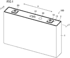
- FIG. 1 is a perspective view schematically showing the configuration of a secondary battery according to one embodiment of the present disclosure.
- FIG. 2 is a sectional view taken along line II-II of FIG. 1 .
- a secondary battery 100 in the present embodiment includes an exterior body 1 having an opening and housing an electrode body 3 and a sealing plate 2 sealing the opening of the exterior body 1.
- the exterior body 1 and the sealing plate 2 are made of aluminum or aluminum alloy, for example.
- a positive electrode external terminal 10 and a negative electrode external terminal 20 are provided outside the sealing plate 2.
- the electrode body 3 has such a structure that a positive electrode plate and a negative electrode plate are wound in a flat shape with a separator being interposed therebetween. Note that in the present embodiment, a longitudinal direction of the sealing plate 2 indicates the direction of an arrow A in FIG. 1 .
- a positive electrode connection member 11 and a negative electrode connection member 21 respectively connected to the positive electrode external terminal 10 and the negative electrode external terminal 20 are provided inside the sealing plate 2. Further, a positive electrode current collector 12 and a negative electrode current collector 22 respectively connected to the positive electrode connection member 11 and the negative electrode connection member 21 are provided inside the sealing plate 2.
- the electrode body 3 has, at an end portion thereof adjacent to the sealing plate 2, a positive electrode tab group 40a and a negative electrode tab group 50a respectively connected to the positive electrode plate and the negative electrode plate, each tab group including a plurality of current collector tabs.
- the positive electrode tab group 40a and the negative electrode tab group 50a are respectively connected to the positive electrode current collector 12 and the negative electrode current collector 22.
- the positive electrode external terminal 10, the positive electrode connection member 11, and the positive electrode current collector 12 are made of aluminum or aluminum alloy, for example.
- the negative electrode external terminal 20, the negative electrode connection member 21, and the negative electrode current collector 22 are made of copper or copper alloy, for example.
- An upper insulating member 13 is arranged between the positive electrode external terminal 10 and the sealing plate 2, and an upper insulating member 23 is arranged between the negative electrode external terminal 20 and the sealing plate 2.
- an insulating member 14 is arranged between the positive electrode connection member 11 and the sealing plate 2, and an insulating member 24 is arranged between the negative electrode connection member 21 and the sealing plate 2.
- the sealing plate 2 is provided with a liquid injection hole (not shown) for injecting an electrolytic solution, and the liquid injection hole is sealed with a sealing member 30.
- the sealing plate 2 is provided with a gas discharge valve 31, and when the internal pressure of the exterior body 1 reaches a predetermined value or greater, gas in the exterior body 1 is discharged to the outside through the broken gas discharge valve 31.
- An insulating electrode body holder 6 is arranged between the exterior body 1 and the electrode body 3.
- FIG. 3A is a plan view of the positive electrode plate 4.
- the positive electrode plate 4 has such a configuration that positive electrode mixture layers containing a positive electrode active material are formed on both surfaces of a positive electrode core.
- a plurality of positive electrode current collector tabs 4a protrudes at predetermined intervals from an end side of the positive electrode plate 4.
- the positive electrode current collector tab 4a may be part of the positive electrode core, or may be another member.
- the positive electrode core is made of aluminum foil or aluminum alloy foil, for example.
- the positive electrode active material is made of lithium-transition metal composite oxide, for example.
- FIG. 3B is a plan view of the negative electrode plate 5.
- the negative electrode plate 5 has such a configuration that negative electrode mixture layers containing a negative electrode active material are formed on both surfaces of a negative electrode core.
- a plurality of negative electrode current collector tabs 5a protrudes at predetermined intervals from an end side of the negative electrode plate 5.
- the negative electrode current collector tab 5a may be part of the negative electrode core, or may be another member.
- the negative electrode core is made of copper foil or copper alloy foil, for example.
- the negative electrode active material is made of a carbon material or a silicon-containing material, for example.
- FIGS. 4A to 4C show the electrode body 3 configured such that the positive electrode plate 4 and the negative electrode plate 5 are wound in a flat shape with a separator being interposed therebetween.
- FIG. 4A is a top view of the electrode body 3
- FIG. 4B is a side view of the electrode body 3
- FIG. 4C is a front view of the electrode body 3.
- the positive electrode tab group 40a and the negative electrode tab group 50a protrude from an end side of the electrode body 3.
- the positive electrode tab group 40a and the negative electrode tab group 50a are configured such that a plurality of positive electrode current collector tabs 4a and a plurality of negative electrode current collector tabs 5a are stacked on each other at predetermined positions.
- the positive electrode tab group 40a and the negative electrode tab group 50a are respectively connected to the later-described positive electrode current collector 12 and the later-described negative electrode current collector 22 with tip end portions of the positive electrode tab group 40a and the negative electrode tab group 50a being bundled together.
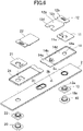
- FIGS. 5 and 6 are exploded perspective views of each configuration of the secondary battery other than the exterior body 1 and the electrode body 3.
- FIG. 5 is an exploded perspective view from the upper side of the sealing plate 2
- FIG. 6 is an exploded perspective view from the lower side of the sealing plate 2. Note that each configuration on a positive electrode side will be described below and each configuration on a negative electrode side is basically the same as that on the positive electrode side.
- the positive electrode external terminal 10 and the upper insulating member 13 are arranged on the upper side of the sealing plate 2.
- the insulating member 14, the positive electrode connection member 11, and the positive electrode current collector 12 are arranged.
- the positive electrode external terminal 10 has a cylindrical protruding portion 10a.
- the upper insulating member 13, the sealing plate 2, the insulating member 14, and the positive electrode connection member 11 are respectively provided with through-holes 13a, 2a, 14a, and 11a through which the protruding portion 10a of the positive electrode external terminal 10 penetrates.
- the sealing plate 2 has a liquid injection hole 2b for injecting an electrolytic solution and a gas discharge valve 31 for discharging gas from the exterior body 1.
- the insulating member 14 is provided with an opening 14b at such a position that the liquid injection hole 2b is not closed.
- the positive electrode current collector 12 has, along the longitudinal direction of the sealing plate 2, a first connection region 12a connected to the positive electrode tab group 40a and a second connection region 12b connected to the positive electrode connection member 11.
- the positive electrode current collector 12 has a step portion 12c between the first connection region 12a and the second connection region 12b, and the first connection region 12a is positioned closer to the sealing plate 2 than the second connection region 12b is.
- the positive electrode current collector 12 is provided with a cutout portion 12d at such a position that the liquid injection hole 2b is not closed.
- the insulating member 24 on the negative electrode side and the negative electrode current collector 22 are not arranged at such positions that the liquid injection hole 2b is closed, and therefore, do not have portions equivalent to the opening 14b and the cutout portion 12d respectively provided at the insulating member 14 and the positive electrode current collector 12.
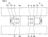
- FIG. 7 is a plan view showing a state in which the positive electrode tab groups 40a, 40b respectively provided at two electrode bodies 3a, 3b having the same configuration are connected to the positive electrode current collector 12, and the negative electrode tab groups 50a, 50b respectively provided at the two electrode bodies 3a, 3b are connected to the negative electrode current collector 22.
- these two electrode bodies 3a, 3b are arranged such that the positive electrode tab groups 40a, 40b face each other and the negative electrode tab groups 50a, 50b face each other. Then, the positive electrode tab groups 40a, 40b are arranged on the first connection region 12a of the positive electrode current collector 12 to be welded to the positive electrode current collector 12 at a welding location 60, and the negative electrode tab groups 50a, 50b are arranged on the first connection region 22a of the negative electrode current collector 22 to be welded to the negative electrode current collector 22 at a welding location 70. Welding can be performed using, e.g., ultrasonic welding, resistance welding, or laser welding.
- the two electrode bodies 3a, 3b are housed in the exterior body 1 with the positive electrode tab groups 40a, 40b and the negative electrode tab groups 50a, 50b being bent and the electrode bodies 3a, 3b being arranged in parallel with each other.
- FIG. 8 is a plan view showing, from the lower side of the sealing plate 2, a state in which the positive electrode external terminal 10, the negative electrode external terminal 20, the positive electrode connection member 11, and the negative electrode connection member 21 are assembled with the sealing plate 2.
- the upper insulating member 13, the sealing plate 2, the insulating member 14, and the positive electrode connection member 11 are arranged such that the positions of the through-holes 13a, 2a, 14a, and 11a respectively provided at the upper insulating member 13, the sealing plate 2, the insulating member 14, and the positive electrode connection member 11 are aligned with each other.
- the protruding portion 10a of the positive electrode external terminal 10 is inserted into the through-holes 13a, 2a, 14a, and 11a, and a tip portion of the protruding portion 10a is crimped onto the positive electrode connection member 11 to fix the positive electrode external terminal 10 and the positive electrode connection member 11 to the sealing plate 2.
- the positive electrode external terminal 10 and the positive electrode connection member 11 may be further welded to each other.
- the insulating member 14 has a recessed portion 14d and the positive electrode connection member 11 is fitted in the recessed portion 14d. Moreover, part of the recessed portion 14d is exposed through the positive electrode connection member 11, and the later-described positive electrode current collector 12 is fitted in such an exposed portion.
- FIG. 9 is a plan view showing a state in which the positive electrode current collector 12 and the negative electrode current collector 22 in the state shown in FIG. 7 are respectively connected to the positive electrode connection member 11 and the negative electrode connection member 21 in the state shown in FIG. 8 .
- the positive electrode current collector 12 is welded to the positive electrode connection member 11 at the second connection region 12b with the first connection region 12a being fitted in the recessed portion 14d of the insulating member 14. Welding can be performed using, e.g., laser welding.
- the plurality of positive electrode current collector tabs 4a and the plurality of negative electrode current collector tabs 5a are formed in advance at the predetermined intervals at the end portions of the positive and negative electrode plates 4, 5 on one side so as to be stacked at predetermined positions when the positive electrode plate 4 and the negative electrode plate 5 are wound in the flat shape to form the electrode body 3.
- these electrode tabs are stacked at positions shifted from the predetermined positions in some cases.
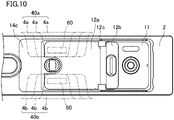
- FIG. 10 is an enlarged plan view of the positive electrode side in FIG. 9 . Note that the electrode bodies 3a, 3b are not shown in FIG. 10 .
- the plurality of positive electrode current collector tabs 4a, 4b forming the positive electrode tab groups 40a, 40b are stacked so as to be shifted from each other in the longitudinal direction of the sealing plate 2.
- the positive electrode tab groups 40a, 40b have such portions (projecting portions) that at least some of the positive electrode current collector tabs 4a, 4b project from the positive electrode current collector 12 (the first connection region 12a) in the longitudinal direction of the sealing plate 2.
- the widths of the positive electrode current collector tabs 4a, 4b in the longitudinal direction of the sealing plate 2 are expanded for increasing the output of the secondary battery, the first connection region 12a of the positive electrode current collector 12 connected to the positive electrode tab groups 40a, 40b are also expanded.
- the positive electrode tab groups 40a, 40b are arranged close to the end of the positive electrode current collector 12 in the longitudinal direction, and for this reason, have more projecting portions.
- the positive electrode tab groups 40a, 40b have more projecting portions.
- the insulating member 14 has an extending portion 14c extending between each projecting portion of the positive electrode tab groups 40a, 40b and the sealing plate 2 in the longitudinal direction of the sealing plate 2.
- the extending portion 14c also projects from the positive electrode current collector 12 in the longitudinal direction of the sealing plate 2.
- the extending portion 14c is provided at the insulating member 14 so that contact of the projecting portions of the positive electrode tab groups 40a, 40b with the sealing plate 2 can be prevented.
- a secondary battery can be provided, which has such a structure that insulation among the positive electrode tab groups 40a, 40b and the sealing plate 2 is maintained.
- contact of the projecting portions of the positive electrode tab groups 40a, 40b with the sealing plate 2 can be prevented even when the widths of the positive electrode current collector tabs 4a, 4b in the longitudinal direction of the sealing plate 2 are expanded.
- a high-power secondary battery can be provided, which has such a structure that the insulation among the positive electrode tab groups 40a, 40b and the sealing plate 2 is maintained.
- the insulating member 24 on the negative electrode side has a similar configuration.
- a secondary battery can be provided, which has such a structure that insulation among the negative electrode tab groups 50a, 50b and the sealing plate 2 is maintained.
- FIGS. 11 and 12 are an enlarged side view showing the positive electrode side in FIG. 9 and a perspective view from the lower side of the sealing plate 2. Note that in FIGS. 11 and 12 , the electrode bodies 3a, 3b, the positive electrode tab groups 40a, 40b, and the negative electrode tab groups 50a, 50b are not shown.
- the positive electrode current collector 12 is welded to the positive electrode connection member 11 with the first connection region 12a connected to the positive electrode tab groups 40a, 40b being fitted in the recessed portion 14d of the insulating member 14.
- the surface of the first connection region 12a on a side adjacent to an electrode body 3a, 3b is flush with the surface of the extending portion 14c of the insulating member 14 on the side adjacent to the electrode body 3a, 3b.
- a clearance S is provided between the sealing plate 2 and the extending portion 14c. This can reduce the weight and cost of the insulating member 14.
- the first connection region 12a of the positive electrode current collector 12 is positioned closer to the sealing plate 2 than the second connection region 12b is as shown in FIG. 2 .
- the end portion of the electrode body 3 adjacent to the sealing plate 2 can be positioned closer to the sealing plate 2.
- the capacity of the secondary battery can be further increased.
- the positive electrode external terminal 10 and the positive electrode connection member 11 are formed as separate members, but may be integrally formed of the same member.
- the negative electrode external terminal 20 and the negative electrode connection member 21 are formed as separate members, but may be integrally formed of the same member.
- the electrode body 3a, 3b having the structure in which the positive electrode plate 4 and the negative electrode plate 5 are wound with the separator being interposed therebetween has been described.
- an electrode body having a structure in which a plurality of positive electrode plates and a plurality of negative electrode plates are stacked with a separator being interposed between adjacent ones of the plates may be used. This is because even in the electrode body having the multilayer structure, a plurality of current collector tabs provided at the positive and negative electrode plates are stacked so as to be shifted from each other and some of these tabs project from positive and negative current collectors in some cases.
- the example where the two electrode bodies 3a, 3b are housed in the exterior body 1 has been described.
- one electrode body or three or more electrode bodies may be used.
- the type of secondary battery in the present embodiment is not particularly limited.
- the present disclosure can be applied to a non-aqueous electrolyte secondary battery such as a lithium ion secondary battery.
Landscapes
- Chemical & Material Sciences (AREA)
- Chemical Kinetics & Catalysis (AREA)
- Electrochemistry (AREA)
- General Chemical & Material Sciences (AREA)
- Connection Of Batteries Or Terminals (AREA)
- Secondary Cells (AREA)
Abstract
Description
- The present disclosure relates to a secondary battery.
- As a current collection structure of a secondary battery configured such that an electrode body is housed in an exterior body, a structure has been known, in which a current collector tab extending from the electrode body toward a sealing plate of the exterior body is connected to an external terminal through a current collector.
- Regarding such a current collection structure,
Patent Document 1 discloses, as an electrode body, a structure in which a positive electrode plate and a negative electrode plate are wound in a flat shape with a separator being interposed therebetween. Each of the positive electrode plate and the negative electrode plate is formed in a band shape, and a plurality of positive and negative electrode current collector tabs is formed at predetermined intervals at one end portion in a width direction. When the positive electrode plate and the negative electrode plate are wound to form the electrode body, the plurality of positive and negative electrode current collector tabs are stacked at predetermined positions to form tab groups. Each of the positive and negative electrode tab groups is bundled, and these tab groups are each connected to positive and negative electrode current collectors. The current collectors are further connected to external terminals to form the current collection structure. - PATENT DOCUMENT 1:
Japanese Unexamined Patent Application Publication (Translation of PCT Application) No. 2018-534725 - In the above-described current collection structure, an insulating member is arranged between the current collector and the sealing plate for electrically insulating a sealing plate from the current collector connected to the external terminal.
- For increasing the output of the secondary battery, it is effective to expand the width of the current collector tab in a longitudinal direction of the sealing plate. For expanding the width of the current collector tab, the region of the current collector connected to the tab group is also expanded. As a result, the tab group is arranged close to an end portion of the current collector in the longitudinal direction.
- The plurality of current collector tabs are formed in advance at predetermined intervals at the end portions of the positive and negative electrode plates on one side so as to be stacked at predetermined positions when the positive electrode plate and the negative electrode plate are wound in a flat shape to form the electrode body. However, due to variation in the thicknesses of the electrode plates, the curvature of the wound electrode body, a pressing direction when the wound electrode body is pressed in the flat shape, etc., these current collector tabs are stacked at positions shifted from the predetermined positions in some cases.
- When the tab group is connected to the current collector with the plurality of current collector tabs being shifted from each other as described above, some of the current collector tabs might project from the current collector in the longitudinal direction of the sealing plate. As a result, a portion of the current collector tab projecting from the current collector might contact the sealing plate, leading to a loss of insulation between the tab group and the sealing plate.
- A secondary battery of the present disclosure includes an electrode body including a positive electrode plate and a negative electrode plate, an exterior body having an opening and housing the electrode body, a sealing plate sealing the opening, an external terminal provided outside the sealing plate, a connection member provided inside the sealing plate and connected to the external terminal, an insulating member provided between the sealing plate and the connection member, and a current collector disposed inside the sealing plate and connected to the connection member and a tab group including a plurality of current collector tabs extending from the positive electrode plate and the negative electrode plate. At least some of the current collector tabs of the tab group have a projecting portion projecting from the current collector in a longitudinal direction of the sealing plate. The insulating member has an extending portion at least extending between the projecting portion and the sealing plate along the longitudinal direction of the sealing plate.
- According to the present disclosure, a secondary battery can be provided, which includes a current collector and has such a structure that insulation between a tab group including a plurality of current collector tabs and a sealing plate is maintained.
-
-
FIG. 1 is a perspective view schematically showing the configuration of a secondary battery in one embodiment of the present disclosure. -
FIG. 2 is a sectional view taken along line II-II ofFIG. 1 . -
FIG. 3A is a plan view of a positive electrode plate. -
FIG. 3B is a plan view of a negative electrode plate. -
FIG. 4A is a top view of an electrode body. -
FIG. 4B is a side view of the electrode body. -
FIG. 4C is a front view of the electrode body. -
FIG. 5 is an exploded perspective view of each configuration of the secondary battery other than an exterior body and the electrode body. -
FIG. 6 is an exploded perspective view of each configuration of the secondary battery other than the exterior body and the electrode body. -
FIG. 7 is a plan view showing a state in which a positive electrode tab group and a negative electrode tab group are respectively connected to a positive electrode current collector and a negative electrode current collector. -
FIG. 8 is a plan view showing a state in which a positive electrode external terminal, a negative electrode external terminal, a positive electrode connection member, and a negative electrode connection member are assembled with a sealing plate. -
FIG. 9 is a plan view showing a state in which the positive electrode current collector and the negative electrode current collector in the state shown inFIG. 7 are respectively connected to the positive electrode connection member and the negative electrode connection member in the state shown inFIG. 8 . -
FIG. 10 is an enlarged plan view of a positive electrode side inFIG. 9 . -
FIG. 11 is an enlarged side view of the positive electrode side inFIG. 9 . -
FIG. 12 is a perspective view from the lower side of the sealing plate inFIG. 9 . - Hereinafter, an embodiment of the present disclosure will be described in detail with reference to the drawings. Note that the present disclosure is not limited to the following embodiment. Further, changes can be made as necessary without departing from a scope in which advantageous effects of the present disclosure are provided.
-
FIG. 1 is a perspective view schematically showing the configuration of a secondary battery according to one embodiment of the present disclosure. Moreover,FIG. 2 is a sectional view taken along line II-II ofFIG. 1 . - As shown in
FIGS. 1 and2 , asecondary battery 100 in the present embodiment includes anexterior body 1 having an opening and housing anelectrode body 3 and asealing plate 2 sealing the opening of theexterior body 1. Theexterior body 1 and thesealing plate 2 are made of aluminum or aluminum alloy, for example. A positive electrodeexternal terminal 10 and a negative electrodeexternal terminal 20 are provided outside thesealing plate 2. Theelectrode body 3 has such a structure that a positive electrode plate and a negative electrode plate are wound in a flat shape with a separator being interposed therebetween. Note that in the present embodiment, a longitudinal direction of thesealing plate 2 indicates the direction of an arrow A inFIG. 1 . - A positive
electrode connection member 11 and a negativeelectrode connection member 21 respectively connected to the positive electrodeexternal terminal 10 and the negative electrodeexternal terminal 20 are provided inside thesealing plate 2. Further, a positive electrodecurrent collector 12 and a negative electrodecurrent collector 22 respectively connected to the positiveelectrode connection member 11 and the negativeelectrode connection member 21 are provided inside thesealing plate 2. - The
electrode body 3 has, at an end portion thereof adjacent to thesealing plate 2, a positiveelectrode tab group 40a and a negativeelectrode tab group 50a respectively connected to the positive electrode plate and the negative electrode plate, each tab group including a plurality of current collector tabs. The positiveelectrode tab group 40a and the negativeelectrode tab group 50a are respectively connected to the positive electrodecurrent collector 12 and the negative electrodecurrent collector 22. - The positive electrode
external terminal 10, the positiveelectrode connection member 11, and the positive electrodecurrent collector 12 are made of aluminum or aluminum alloy, for example. The negative electrodeexternal terminal 20, the negativeelectrode connection member 21, and the negative electrodecurrent collector 22 are made of copper or copper alloy, for example. - An upper
insulating member 13 is arranged between the positive electrodeexternal terminal 10 and thesealing plate 2, and an upper insulatingmember 23 is arranged between the negative electrodeexternal terminal 20 and thesealing plate 2. Moreover, aninsulating member 14 is arranged between the positiveelectrode connection member 11 and thesealing plate 2, and aninsulating member 24 is arranged between the negativeelectrode connection member 21 and thesealing plate 2. With this configuration, each of the positive electrodeexternal terminal 10, the negative electrodeexternal terminal 20, the positiveelectrode connection member 11, and the negativeelectrode connection member 21 is electrically insulated from thesealing plate 2. - The sealing
plate 2 is provided with a liquid injection hole (not shown) for injecting an electrolytic solution, and the liquid injection hole is sealed with a sealingmember 30. The sealingplate 2 is provided with agas discharge valve 31, and when the internal pressure of theexterior body 1 reaches a predetermined value or greater, gas in theexterior body 1 is discharged to the outside through the brokengas discharge valve 31. An insulatingelectrode body holder 6 is arranged between theexterior body 1 and theelectrode body 3. - Next, the method for assembling the secondary battery in the present embodiment and details of each configuration will be described with reference to
FIGS. 3A to 9 . -
FIG. 3A is a plan view of thepositive electrode plate 4. Thepositive electrode plate 4 has such a configuration that positive electrode mixture layers containing a positive electrode active material are formed on both surfaces of a positive electrode core. A plurality of positive electrodecurrent collector tabs 4a protrudes at predetermined intervals from an end side of thepositive electrode plate 4. The positive electrodecurrent collector tab 4a may be part of the positive electrode core, or may be another member. The positive electrode core is made of aluminum foil or aluminum alloy foil, for example. Moreover, the positive electrode active material is made of lithium-transition metal composite oxide, for example. -
FIG. 3B is a plan view of thenegative electrode plate 5. Thenegative electrode plate 5 has such a configuration that negative electrode mixture layers containing a negative electrode active material are formed on both surfaces of a negative electrode core. A plurality of negative electrodecurrent collector tabs 5a protrudes at predetermined intervals from an end side of thenegative electrode plate 5. The negative electrodecurrent collector tab 5a may be part of the negative electrode core, or may be another member. The negative electrode core is made of copper foil or copper alloy foil, for example. Moreover, the negative electrode active material is made of a carbon material or a silicon-containing material, for example. -
FIGS. 4A to 4C show theelectrode body 3 configured such that thepositive electrode plate 4 and thenegative electrode plate 5 are wound in a flat shape with a separator being interposed therebetween. Here,FIG. 4A is a top view of theelectrode body 3,FIG. 4B is a side view of theelectrode body 3, andFIG. 4C is a front view of theelectrode body 3. - As shown in
FIGS. 4A to 4C , the positiveelectrode tab group 40a and the negativeelectrode tab group 50a protrude from an end side of theelectrode body 3. When thepositive electrode plate 4 and thenegative electrode plate 5 are wound in the flat shape to form theelectrode body 3, the positiveelectrode tab group 40a and the negativeelectrode tab group 50a are configured such that a plurality of positive electrodecurrent collector tabs 4a and a plurality of negative electrodecurrent collector tabs 5a are stacked on each other at predetermined positions. Note that the positiveelectrode tab group 40a and the negativeelectrode tab group 50a are respectively connected to the later-described positive electrodecurrent collector 12 and the later-described negative electrodecurrent collector 22 with tip end portions of the positiveelectrode tab group 40a and the negativeelectrode tab group 50a being bundled together. -
FIGS. 5 and6 are exploded perspective views of each configuration of the secondary battery other than theexterior body 1 and theelectrode body 3. Here,FIG. 5 is an exploded perspective view from the upper side of the sealingplate 2, andFIG. 6 is an exploded perspective view from the lower side of the sealingplate 2. Note that each configuration on a positive electrode side will be described below and each configuration on a negative electrode side is basically the same as that on the positive electrode side. - As shown in
FIGS. 5 and6 , the positive electrodeexternal terminal 10 and the upper insulatingmember 13 are arranged on the upper side of the sealingplate 2. On the lower side of the sealingplate 2, the insulatingmember 14, the positiveelectrode connection member 11, and the positive electrodecurrent collector 12 are arranged. - The positive electrode
external terminal 10 has a cylindrical protrudingportion 10a. The upper insulatingmember 13, the sealingplate 2, the insulatingmember 14, and the positiveelectrode connection member 11 are respectively provided with through-holes portion 10a of the positive electrodeexternal terminal 10 penetrates. - The sealing
plate 2 has aliquid injection hole 2b for injecting an electrolytic solution and agas discharge valve 31 for discharging gas from theexterior body 1. The insulatingmember 14 is provided with anopening 14b at such a position that theliquid injection hole 2b is not closed. - The positive electrode
current collector 12 has, along the longitudinal direction of the sealingplate 2, afirst connection region 12a connected to the positiveelectrode tab group 40a and asecond connection region 12b connected to the positiveelectrode connection member 11. The positive electrodecurrent collector 12 has astep portion 12c between thefirst connection region 12a and thesecond connection region 12b, and thefirst connection region 12a is positioned closer to the sealingplate 2 than thesecond connection region 12b is. The positive electrodecurrent collector 12 is provided with acutout portion 12d at such a position that theliquid injection hole 2b is not closed. - Note that the insulating
member 24 on the negative electrode side and the negative electrodecurrent collector 22 are not arranged at such positions that theliquid injection hole 2b is closed, and therefore, do not have portions equivalent to theopening 14b and thecutout portion 12d respectively provided at the insulatingmember 14 and the positive electrodecurrent collector 12. -
FIG. 7 is a plan view showing a state in which the positiveelectrode tab groups electrode bodies current collector 12, and the negativeelectrode tab groups electrode bodies current collector 22. - Specifically, as shown in
FIG. 7 , these twoelectrode bodies electrode tab groups electrode tab groups electrode tab groups first connection region 12a of the positive electrodecurrent collector 12 to be welded to the positive electrodecurrent collector 12 at awelding location 60, and the negativeelectrode tab groups first connection region 22a of the negative electrodecurrent collector 22 to be welded to the negative electrodecurrent collector 22 at awelding location 70. Welding can be performed using, e.g., ultrasonic welding, resistance welding, or laser welding. - Note that the two
electrode bodies exterior body 1 with the positiveelectrode tab groups electrode tab groups electrode bodies -
FIG. 8 is a plan view showing, from the lower side of the sealingplate 2, a state in which the positive electrodeexternal terminal 10, the negative electrodeexternal terminal 20, the positiveelectrode connection member 11, and the negativeelectrode connection member 21 are assembled with the sealingplate 2. - Specifically, as shown in
FIGS. 5 and6 , the upper insulatingmember 13, the sealingplate 2, the insulatingmember 14, and the positiveelectrode connection member 11 are arranged such that the positions of the through-holes member 13, the sealingplate 2, the insulatingmember 14, and the positiveelectrode connection member 11 are aligned with each other. Then, the protrudingportion 10a of the positive electrodeexternal terminal 10 is inserted into the through-holes portion 10a is crimped onto the positiveelectrode connection member 11 to fix the positive electrodeexternal terminal 10 and the positiveelectrode connection member 11 to the sealingplate 2. Note that at the crimped portion, the positive electrodeexternal terminal 10 and the positiveelectrode connection member 11 may be further welded to each other. - Note that the insulating
member 14 has a recessedportion 14d and the positiveelectrode connection member 11 is fitted in the recessedportion 14d. Moreover, part of the recessedportion 14d is exposed through the positiveelectrode connection member 11, and the later-described positive electrodecurrent collector 12 is fitted in such an exposed portion. -
FIG. 9 is a plan view showing a state in which the positive electrodecurrent collector 12 and the negative electrodecurrent collector 22 in the state shown inFIG. 7 are respectively connected to the positiveelectrode connection member 11 and the negativeelectrode connection member 21 in the state shown inFIG. 8 . - As shown in
FIG. 9 , the positive electrodecurrent collector 12 is welded to the positiveelectrode connection member 11 at thesecond connection region 12b with thefirst connection region 12a being fitted in the recessedportion 14d of the insulatingmember 14. Welding can be performed using, e.g., laser welding. - As shown in
FIGS. 3A, 3B , and4A to 4C , the plurality of positive electrodecurrent collector tabs 4a and the plurality of negative electrodecurrent collector tabs 5a are formed in advance at the predetermined intervals at the end portions of the positive andnegative electrode plates positive electrode plate 4 and thenegative electrode plate 5 are wound in the flat shape to form theelectrode body 3. However, due to variation in the thicknesses of thepositive electrode plate 4 and thenegative electrode plate 5, the curvature of theelectrode body 3, a pressing direction when thewound electrode body 3 is pressed in the flat shape, etc., these electrode tabs are stacked at positions shifted from the predetermined positions in some cases. -
FIG. 10 is an enlarged plan view of the positive electrode side inFIG. 9 . Note that theelectrode bodies FIG. 10 . - As shown in
FIG. 10 , the plurality of positive electrodecurrent collector tabs electrode tab groups FIG. 10 ) are stacked so as to be shifted from each other in the longitudinal direction of the sealingplate 2. Thus, the positiveelectrode tab groups current collector tabs first connection region 12a) in the longitudinal direction of the sealingplate 2. - Particularly, when the widths of the positive electrode
current collector tabs plate 2 are expanded for increasing the output of the secondary battery, thefirst connection region 12a of the positive electrodecurrent collector 12 connected to the positiveelectrode tab groups electrode tab groups current collector 12 in the longitudinal direction, and for this reason, have more projecting portions. Moreover, also in a case where, in thefirst connection region 12a, awelding location 60 between the positive electrodecurrent collector 12 and the positiveelectrode tab group 40a and awelding location 60 between the positive electrodecurrent collector 12 and the positiveelectrode tab group 40b are positioned closer to the end of the positive electrodecurrent collector 12 than thestep portion 12c is, the positiveelectrode tab groups - In the present embodiment, the insulating
member 14 has an extendingportion 14c extending between each projecting portion of the positiveelectrode tab groups plate 2 in the longitudinal direction of the sealingplate 2. Thus, the extendingportion 14c also projects from the positive electrodecurrent collector 12 in the longitudinal direction of the sealingplate 2. - According to the present embodiment, the extending
portion 14c is provided at the insulatingmember 14 so that contact of the projecting portions of the positiveelectrode tab groups plate 2 can be prevented. Accordingly, a secondary battery can be provided, which has such a structure that insulation among the positiveelectrode tab groups plate 2 is maintained. Particularly, contact of the projecting portions of the positiveelectrode tab groups plate 2 can be prevented even when the widths of the positive electrodecurrent collector tabs plate 2 are expanded. Thus, a high-power secondary battery can be provided, which has such a structure that the insulation among the positiveelectrode tab groups plate 2 is maintained. - Note that in the present embodiment, the insulating
member 24 on the negative electrode side has a similar configuration. Thus, a secondary battery can be provided, which has such a structure that insulation among the negativeelectrode tab groups plate 2 is maintained. -
FIGS. 11 and 12 are an enlarged side view showing the positive electrode side inFIG. 9 and a perspective view from the lower side of the sealingplate 2. Note that inFIGS. 11 and 12 , theelectrode bodies electrode tab groups electrode tab groups - As shown in
FIGS. 11 and 12 , the positive electrodecurrent collector 12 is welded to the positiveelectrode connection member 11 with thefirst connection region 12a connected to the positiveelectrode tab groups portion 14d of the insulatingmember 14. The surface of thefirst connection region 12a on a side adjacent to anelectrode body portion 14c of the insulatingmember 14 on the side adjacent to theelectrode body current collector tabs current collector tabs first connection region 12a) and the insulating member 14 (the extendingportion 14c). - Moreover, as shown in
FIGS. 11 and 12 , a clearance S is provided between the sealingplate 2 and the extendingportion 14c. This can reduce the weight and cost of the insulatingmember 14. - In the present embodiment, the
first connection region 12a of the positive electrodecurrent collector 12 is positioned closer to the sealingplate 2 than thesecond connection region 12b is as shown inFIG. 2 . With this configuration, the end portion of theelectrode body 3 adjacent to the sealingplate 2 can be positioned closer to the sealingplate 2. As a result, the capacity of the secondary battery can be further increased. - The present disclosure has been described above with reference to the preferred embodiment, but such description is not limited and various modifications can be made, needless to say.
- For example, in the above-described embodiment, the positive electrode
external terminal 10 and the positiveelectrode connection member 11 are formed as separate members, but may be integrally formed of the same member. Similarly, the negative electrodeexternal terminal 20 and the negativeelectrode connection member 21 are formed as separate members, but may be integrally formed of the same member. - In the above-described embodiment, use of the
electrode body positive electrode plate 4 and thenegative electrode plate 5 are wound with the separator being interposed therebetween has been described. However, an electrode body having a structure in which a plurality of positive electrode plates and a plurality of negative electrode plates are stacked with a separator being interposed between adjacent ones of the plates may be used. This is because even in the electrode body having the multilayer structure, a plurality of current collector tabs provided at the positive and negative electrode plates are stacked so as to be shifted from each other and some of these tabs project from positive and negative current collectors in some cases. - In the above-described embodiment, the example where the two
electrode bodies exterior body 1 has been described. However, one electrode body or three or more electrode bodies may be used. - The type of secondary battery in the present embodiment is not particularly limited. For example, the present disclosure can be applied to a non-aqueous electrolyte secondary battery such as a lithium ion secondary battery.
-
- 1
- Exterior Body
- 2
- Sealing Plate
- 2b
- Liquid Inj ecti on Hole
- 3, 3a, 3b
- Electrode Body
- 4
- Positive Electrode Plate
- 4a, 4b
- Positive Electrode Current Collector Tab
- 5
- Negative Electrode Plate
- 5a, 5b
- Negative Electrode Current Collector Tab
- 6
- Electrode Body Holder
- 10
- Positive Electrode External Terminal
- 10a
- Protruding Portion
- 11
- Positive Electrode Connection Member
- 12
- Positive Electrode Current Collector
- 12a
- First Connection Region
- 12b
- Second Connection Region
- 12c
- Step Portion
- 12d
- Cutout Portion
- 13, 23
- Upper Insulating Member
- 13a, 2a, 14a, 11a
- Through-Hole
- 14,24
- Insulating Member
- 14b
- Opening
- 14c
- Extending Portion
- 14d
- Recessed Portion
- 20
- Negative Electrode External Terminal
- 21
- Negative Electrode Connection Member
- 22
- Negative Electrode Current Collector
- 22a
- First Connection Region
- 30
- Sealing Member
- 31
- Gas Discharge Valve
- 40a, 40b
- Positive Electrode Tab Group
- 50a, 50b
- Negative Electrode Tab Group
- 60, 70
- Welding Location
- 100
- Secondary Battery
Claims (7)
- A secondary battery comprising:an electrode body including a positive electrode plate and a negative electrode plate;an exterior body having an opening and housing the electrode body;a sealing plate sealing the opening;an external terminal provided outside the sealing plate;a connection member provided inside the sealing plate and connected to the external terminal;an insulating member provided between the sealing plate and the connection member;
anda current collector disposed inside the sealing plate and connected to the connection member and a tab group including a plurality of current collector tabs extending from the positive electrode plate and the negative electrode plate,at least some of the current collector tabs of the tab group having a projecting portion projecting from the current collector in a longitudinal direction of the sealing plate,the insulating member having an extending portion at least extending between the projecting portion and the sealing plate along the longitudinal direction of the sealing plate. - The secondary battery of claim 1, wherein
the current collector has a portion connected to the tab group, and a surface of the portion of the current collector on a side adjacent to the electrode body is flush with a surface of the extending portion of the insulating member on the side adjacent to the electrode body. - The secondary battery of claim 1, wherein
a clearance is provided between the sealing plate and the extending portion. - The secondary battery of claim 1, whereinthe current collector has a first connection region connected to the tab group and a second connection region connected to the connection member, and has a step portion between the first connection region and the second connection region, andthe first connection region is positioned closer to the sealing plate than the second connection region is.
- The secondary battery of claim 4, wherein,
in the first connection region, a joint portion between the current collector and the tab group is positioned closer to an end of the current collector than the step portion is. - The secondary battery of claim 1, wherein
the external terminal and the connection member are integrally formed of an identical member. - The secondary battery of claim 1, wherein
the electrode body has such a structure that the positive electrode plate and the negative electrode plate are wound with a separator being interposed between the positive electrode plate and the negative electrode plate.
Applications Claiming Priority (2)
| Application Number | Priority Date | Filing Date | Title |
|---|---|---|---|
| JP2019175471 | 2019-09-26 | ||
| PCT/JP2020/034402 WO2021060007A1 (en) | 2019-09-26 | 2020-09-11 | Secondary battery |
Publications (3)
| Publication Number | Publication Date |
|---|---|
| EP4037092A1 true EP4037092A1 (en) | 2022-08-03 |
| EP4037092A4 EP4037092A4 (en) | 2023-03-15 |
| EP4037092B1 EP4037092B1 (en) | 2026-02-25 |
Family
ID=75166673
Family Applications (1)
| Application Number | Title | Priority Date | Filing Date |
|---|---|---|---|
| EP20869335.8A Active EP4037092B1 (en) | 2019-09-26 | 2020-09-11 | Secondary battery |
Country Status (5)
| Country | Link |
|---|---|
| US (1) | US12597681B2 (en) |
| EP (1) | EP4037092B1 (en) |
| JP (2) | JP7615038B2 (en) |
| CN (2) | CN114175366B (en) |
| WO (1) | WO2021060007A1 (en) |
Family Cites Families (15)
| Publication number | Priority date | Publication date | Assignee | Title |
|---|---|---|---|---|
| JP4797236B2 (en) * | 2000-11-17 | 2011-10-19 | 株式会社Gsユアサ | battery |
| JP4079326B2 (en) * | 2003-04-25 | 2008-04-23 | 日立マクセル株式会社 | Non-aqueous electrolyte battery |
| JP2006302509A (en) * | 2005-04-15 | 2006-11-02 | Sanyo Electric Co Ltd | battery |
| JP5114036B2 (en) * | 2006-09-08 | 2013-01-09 | Necエナジーデバイス株式会社 | Manufacturing method of stacked battery |
| JP2010118315A (en) | 2008-11-14 | 2010-05-27 | Toshiba Corp | Nonaqueous electrolyte battery |
| JP2011014297A (en) * | 2009-06-30 | 2011-01-20 | Panasonic Corp | Wound electrode group and battery |
| JP5566651B2 (en) * | 2009-09-25 | 2014-08-06 | 株式会社東芝 | Battery and manufacturing method thereof |
| KR101427018B1 (en) * | 2010-02-17 | 2014-08-06 | 가부시끼가이샤 도시바 | Battery and method for producing same |
| JP5586263B2 (en) * | 2010-02-17 | 2014-09-10 | 株式会社東芝 | Square battery and method of manufacturing the same |
| JP2013030385A (en) * | 2011-07-29 | 2013-02-07 | Panasonic Corp | Laminate battery |
| JP6146536B2 (en) * | 2014-04-24 | 2017-06-14 | 株式会社豊田自動織機 | Power storage device |
| JP6702303B2 (en) | 2015-03-13 | 2020-06-03 | 株式会社豊田自動織機 | Power storage device |
| JP2017059507A (en) | 2015-09-18 | 2017-03-23 | リチウム エナジー アンド パワー ゲゼルシャフト ミット ベシュレンクテル ハフッング ウント コンパニー コマンディトゲゼルシャフトLithium Energy and Power GmbH & Co. KG | Power storage device |
| JP6935798B2 (en) * | 2016-07-29 | 2021-09-15 | 三洋電機株式会社 | How to manufacture a secondary battery |
| JP6922328B2 (en) * | 2017-03-29 | 2021-08-18 | 株式会社豊田自動織機 | Manufacturing method of electrode assembly |
-
2020
- 2020-09-11 CN CN202080054547.3A patent/CN114175366B/en active Active
- 2020-09-11 JP JP2021548792A patent/JP7615038B2/en active Active
- 2020-09-11 WO PCT/JP2020/034402 patent/WO2021060007A1/en not_active Ceased
- 2020-09-11 US US17/635,903 patent/US12597681B2/en active Active
- 2020-09-11 EP EP20869335.8A patent/EP4037092B1/en active Active
- 2020-09-11 CN CN202410942088.2A patent/CN118867500A/en active Pending
-
2024
- 2024-12-27 JP JP2024232552A patent/JP7840393B2/en active Active
Also Published As
| Publication number | Publication date |
|---|---|
| CN114175366B (en) | 2024-07-30 |
| EP4037092A4 (en) | 2023-03-15 |
| CN114175366A (en) | 2022-03-11 |
| CN118867500A (en) | 2024-10-29 |
| EP4037092B1 (en) | 2026-02-25 |
| WO2021060007A1 (en) | 2021-04-01 |
| JPWO2021060007A1 (en) | 2021-04-01 |
| US12597681B2 (en) | 2026-04-07 |
| US20220302559A1 (en) | 2022-09-22 |
| JP2025038248A (en) | 2025-03-18 |
| JP7840393B2 (en) | 2026-04-03 |
| JP7615038B2 (en) | 2025-01-16 |
Similar Documents
| Publication | Publication Date | Title |
|---|---|---|
| US20250192345A1 (en) | Secondary battery | |
| EP3852165B1 (en) | Secondary battery and manufacturing method for secondary battery | |
| EP2299523B1 (en) | Battery and method of manufacturing same | |
| CN114843668A (en) | Secondary cell's top cap subassembly, secondary cell and battery module | |
| JP2006040899A (en) | Secondary battery | |
| JP2020107464A (en) | Secondary battery and battery pack | |
| US10424809B2 (en) | Secondary battery, method for manufacturing same, and battery pack employing same | |
| EP4080639A1 (en) | Non-aqueous electrolyte secondary battery | |
| CN112335085B (en) | Electrode assembly, secondary battery including the same, and method for manufacturing the same | |
| US20230033391A1 (en) | Non-aqueous electrolyte secondary battery | |
| US20110305942A1 (en) | Rechargeable battery pack | |
| US20210391631A1 (en) | Battery and manufacturing method of battery | |
| US12266807B2 (en) | Rectangular secondary cell and method for manufacturing same | |
| JP2018006138A (en) | Electrode for power storage device, and power storage device employing the same | |
| KR100590009B1 (en) | Secondary Battery and Electrode Assembly Used in the Same | |
| EP4037092B1 (en) | Secondary battery | |
| US12476338B2 (en) | Secondary battery | |
| CN111755655B (en) | Secondary battery | |
| US20230261344A1 (en) | Battery cell | |
| US12412961B2 (en) | Square secondary battery | |
| JP5790602B2 (en) | Secondary battery | |
| KR100686811B1 (en) | Cylindrical lithium secondary battery | |
| KR20250013052A (en) | Electrode assembly and rechargeable battery including the same | |
| KR20040110330A (en) | Secondary Battery |
Legal Events
| Date | Code | Title | Description |
|---|---|---|---|
| STAA | Information on the status of an ep patent application or granted ep patent |
Free format text: STATUS: THE INTERNATIONAL PUBLICATION HAS BEEN MADE |
|
| PUAI | Public reference made under article 153(3) epc to a published international application that has entered the european phase |
Free format text: ORIGINAL CODE: 0009012 |
|
| STAA | Information on the status of an ep patent application or granted ep patent |
Free format text: STATUS: REQUEST FOR EXAMINATION WAS MADE |
|
| 17P | Request for examination filed |
Effective date: 20220210 |
|
| AK | Designated contracting states |
Kind code of ref document: A1 Designated state(s): AL AT BE BG CH CY CZ DE DK EE ES FI FR GB GR HR HU IE IS IT LI LT LU LV MC MK MT NL NO PL PT RO RS SE SI SK SM TR |
|
| DAV | Request for validation of the european patent (deleted) | ||
| DAX | Request for extension of the european patent (deleted) | ||
| A4 | Supplementary search report drawn up and despatched |
Effective date: 20230213 |
|
| RIC1 | Information provided on ipc code assigned before grant |
Ipc: H01M 50/54 20210101ALI20230207BHEP Ipc: H01M 50/184 20210101ALI20230207BHEP Ipc: H01M 10/0587 20100101ALI20230207BHEP Ipc: H01M 50/538 20210101ALI20230207BHEP Ipc: H01M 50/543 20210101ALI20230207BHEP Ipc: H01M 50/531 20210101ALI20230207BHEP Ipc: H01M 50/147 20210101ALI20230207BHEP Ipc: H01M 50/572 20210101AFI20230207BHEP |
|
| GRAP | Despatch of communication of intention to grant a patent |
Free format text: ORIGINAL CODE: EPIDOSNIGR1 |
|
| STAA | Information on the status of an ep patent application or granted ep patent |
Free format text: STATUS: GRANT OF PATENT IS INTENDED |
|
| INTG | Intention to grant announced |
Effective date: 20250924 |
|
| GRAS | Grant fee paid |
Free format text: ORIGINAL CODE: EPIDOSNIGR3 |
|
| GRAA | (expected) grant |
Free format text: ORIGINAL CODE: 0009210 |
|
| STAA | Information on the status of an ep patent application or granted ep patent |
Free format text: STATUS: THE PATENT HAS BEEN GRANTED |
|
| AK | Designated contracting states |
Kind code of ref document: B1 Designated state(s): AL AT BE BG CH CY CZ DE DK EE ES FI FR GB GR HR HU IE IS IT LI LT LU LV MC MK MT NL NO PL PT RO RS SE SI SK SM TR |
|
| REG | Reference to a national code |
Ref country code: CH Ref legal event code: F10 Free format text: ST27 STATUS EVENT CODE: U-0-0-F10-F00 (AS PROVIDED BY THE NATIONAL OFFICE) Effective date: 20260225 Ref country code: GB Ref legal event code: FG4D |
|
| REG | Reference to a national code |
Ref country code: DE Ref legal event code: R096 Ref document number: 602020067675 Country of ref document: DE |
|
| REG | Reference to a national code |
Ref country code: IE Ref legal event code: FG4D |