EP4037083B1 - Schutzanordnung und batteriegehäuse damit - Google Patents
Schutzanordnung und batteriegehäuse damit Download PDFInfo
- Publication number
- EP4037083B1 EP4037083B1 EP21154717.9A EP21154717A EP4037083B1 EP 4037083 B1 EP4037083 B1 EP 4037083B1 EP 21154717 A EP21154717 A EP 21154717A EP 4037083 B1 EP4037083 B1 EP 4037083B1
- Authority
- EP
- European Patent Office
- Prior art keywords
- bottom cover
- battery
- coupled state
- battery housing
- cross
- Prior art date
- Legal status (The legal status is an assumption and is not a legal conclusion. Google has not performed a legal analysis and makes no representation as to the accuracy of the status listed.)
- Active
Links
Images


Classifications
-
- H—ELECTRICITY
- H01—ELECTRIC ELEMENTS
- H01M—PROCESSES OR MEANS, e.g. BATTERIES, FOR THE DIRECT CONVERSION OF CHEMICAL ENERGY INTO ELECTRICAL ENERGY
- H01M50/00—Constructional details or processes of manufacture of the non-active parts of electrochemical cells other than fuel cells, e.g. hybrid cells
- H01M50/20—Mountings; Secondary casings or frames; Racks, modules or packs; Suspension devices; Shock absorbers; Transport or carrying devices; Holders
-
- B—PERFORMING OPERATIONS; TRANSPORTING
- B60—VEHICLES IN GENERAL
- B60K—ARRANGEMENT OR MOUNTING OF PROPULSION UNITS OR OF TRANSMISSIONS IN VEHICLES; ARRANGEMENT OR MOUNTING OF PLURAL DIVERSE PRIME-MOVERS IN VEHICLES; AUXILIARY DRIVES FOR VEHICLES; INSTRUMENTATION OR DASHBOARDS FOR VEHICLES; ARRANGEMENTS IN CONNECTION WITH COOLING, AIR INTAKE, GAS EXHAUST OR FUEL SUPPLY OF PROPULSION UNITS IN VEHICLES
- B60K1/00—Arrangement or mounting of electrical propulsion units
- B60K1/04—Arrangement or mounting of electrical propulsion units of the electric storage means for propulsion
-
- B—PERFORMING OPERATIONS; TRANSPORTING
- B60—VEHICLES IN GENERAL
- B60L—PROPULSION OF ELECTRICALLY-PROPELLED VEHICLES; SUPPLYING ELECTRIC POWER FOR AUXILIARY EQUIPMENT OF ELECTRICALLY-PROPELLED VEHICLES; ELECTRODYNAMIC BRAKE SYSTEMS FOR VEHICLES IN GENERAL; MAGNETIC SUSPENSION OR LEVITATION FOR VEHICLES; MONITORING OPERATING VARIABLES OF ELECTRICALLY-PROPELLED VEHICLES; ELECTRIC SAFETY DEVICES FOR ELECTRICALLY-PROPELLED VEHICLES
- B60L3/00—Electric devices on electrically-propelled vehicles for safety purposes; Monitoring operating variables, e.g. speed, deceleration or energy consumption
- B60L3/0007—Measures or means for preventing or attenuating collisions
-
- B—PERFORMING OPERATIONS; TRANSPORTING
- B60—VEHICLES IN GENERAL
- B60L—PROPULSION OF ELECTRICALLY-PROPELLED VEHICLES; SUPPLYING ELECTRIC POWER FOR AUXILIARY EQUIPMENT OF ELECTRICALLY-PROPELLED VEHICLES; ELECTRODYNAMIC BRAKE SYSTEMS FOR VEHICLES IN GENERAL; MAGNETIC SUSPENSION OR LEVITATION FOR VEHICLES; MONITORING OPERATING VARIABLES OF ELECTRICALLY-PROPELLED VEHICLES; ELECTRIC SAFETY DEVICES FOR ELECTRICALLY-PROPELLED VEHICLES
- B60L50/00—Electric propulsion with power supplied within the vehicle
- B60L50/50—Electric propulsion with power supplied within the vehicle using propulsion power supplied by batteries or fuel cells
- B60L50/60—Electric propulsion with power supplied within the vehicle using propulsion power supplied by batteries or fuel cells using power supplied by batteries
- B60L50/64—Constructional details of batteries specially adapted for electric vehicles
-
- B—PERFORMING OPERATIONS; TRANSPORTING
- B60—VEHICLES IN GENERAL
- B60L—PROPULSION OF ELECTRICALLY-PROPELLED VEHICLES; SUPPLYING ELECTRIC POWER FOR AUXILIARY EQUIPMENT OF ELECTRICALLY-PROPELLED VEHICLES; ELECTRODYNAMIC BRAKE SYSTEMS FOR VEHICLES IN GENERAL; MAGNETIC SUSPENSION OR LEVITATION FOR VEHICLES; MONITORING OPERATING VARIABLES OF ELECTRICALLY-PROPELLED VEHICLES; ELECTRIC SAFETY DEVICES FOR ELECTRICALLY-PROPELLED VEHICLES
- B60L50/00—Electric propulsion with power supplied within the vehicle
- B60L50/50—Electric propulsion with power supplied within the vehicle using propulsion power supplied by batteries or fuel cells
- B60L50/60—Electric propulsion with power supplied within the vehicle using propulsion power supplied by batteries or fuel cells using power supplied by batteries
- B60L50/66—Arrangements of batteries
-
- B—PERFORMING OPERATIONS; TRANSPORTING
- B62—LAND VEHICLES FOR TRAVELLING OTHERWISE THAN ON RAILS
- B62D—MOTOR VEHICLES; TRAILERS
- B62D25/00—Superstructure or monocoque structure sub-units; Parts or details thereof not otherwise provided for
- B62D25/20—Floors or bottom sub-units
-
- H—ELECTRICITY
- H01—ELECTRIC ELEMENTS
- H01M—PROCESSES OR MEANS, e.g. BATTERIES, FOR THE DIRECT CONVERSION OF CHEMICAL ENERGY INTO ELECTRICAL ENERGY
- H01M10/00—Secondary cells; Manufacture thereof
- H01M10/05—Accumulators with non-aqueous electrolyte
- H01M10/052—Li-accumulators
-
- H—ELECTRICITY
- H01—ELECTRIC ELEMENTS
- H01M—PROCESSES OR MEANS, e.g. BATTERIES, FOR THE DIRECT CONVERSION OF CHEMICAL ENERGY INTO ELECTRICAL ENERGY
- H01M50/00—Constructional details or processes of manufacture of the non-active parts of electrochemical cells other than fuel cells, e.g. hybrid cells
- H01M50/20—Mountings; Secondary casings or frames; Racks, modules or packs; Suspension devices; Shock absorbers; Transport or carrying devices; Holders
- H01M50/233—Mountings; Secondary casings or frames; Racks, modules or packs; Suspension devices; Shock absorbers; Transport or carrying devices; Holders characterised by physical properties of casings or racks, e.g. dimensions
- H01M50/242—Mountings; Secondary casings or frames; Racks, modules or packs; Suspension devices; Shock absorbers; Transport or carrying devices; Holders characterised by physical properties of casings or racks, e.g. dimensions adapted for protecting batteries against vibrations, collision impact or swelling
-
- H—ELECTRICITY
- H01—ELECTRIC ELEMENTS
- H01M—PROCESSES OR MEANS, e.g. BATTERIES, FOR THE DIRECT CONVERSION OF CHEMICAL ENERGY INTO ELECTRICAL ENERGY
- H01M50/00—Constructional details or processes of manufacture of the non-active parts of electrochemical cells other than fuel cells, e.g. hybrid cells
- H01M50/20—Mountings; Secondary casings or frames; Racks, modules or packs; Suspension devices; Shock absorbers; Transport or carrying devices; Holders
- H01M50/249—Mountings; Secondary casings or frames; Racks, modules or packs; Suspension devices; Shock absorbers; Transport or carrying devices; Holders specially adapted for aircraft or vehicles, e.g. cars or trains
-
- B—PERFORMING OPERATIONS; TRANSPORTING
- B60—VEHICLES IN GENERAL
- B60K—ARRANGEMENT OR MOUNTING OF PROPULSION UNITS OR OF TRANSMISSIONS IN VEHICLES; ARRANGEMENT OR MOUNTING OF PLURAL DIVERSE PRIME-MOVERS IN VEHICLES; AUXILIARY DRIVES FOR VEHICLES; INSTRUMENTATION OR DASHBOARDS FOR VEHICLES; ARRANGEMENTS IN CONNECTION WITH COOLING, AIR INTAKE, GAS EXHAUST OR FUEL SUPPLY OF PROPULSION UNITS IN VEHICLES
- B60K1/00—Arrangement or mounting of electrical propulsion units
- B60K1/04—Arrangement or mounting of electrical propulsion units of the electric storage means for propulsion
- B60K2001/0405—Arrangement or mounting of electrical propulsion units of the electric storage means for propulsion characterised by their position
- B60K2001/0438—Arrangement under the floor
-
- B—PERFORMING OPERATIONS; TRANSPORTING
- B60—VEHICLES IN GENERAL
- B60Y—INDEXING SCHEME RELATING TO ASPECTS CROSS-CUTTING VEHICLE TECHNOLOGY
- B60Y2200/00—Type of vehicle
- B60Y2200/90—Vehicles comprising electric prime movers
- B60Y2200/91—Electric vehicles
-
- B—PERFORMING OPERATIONS; TRANSPORTING
- B60—VEHICLES IN GENERAL
- B60Y—INDEXING SCHEME RELATING TO ASPECTS CROSS-CUTTING VEHICLE TECHNOLOGY
- B60Y2200/00—Type of vehicle
- B60Y2200/90—Vehicles comprising electric prime movers
- B60Y2200/92—Hybrid vehicles
-
- H—ELECTRICITY
- H01—ELECTRIC ELEMENTS
- H01M—PROCESSES OR MEANS, e.g. BATTERIES, FOR THE DIRECT CONVERSION OF CHEMICAL ENERGY INTO ELECTRICAL ENERGY
- H01M2220/00—Batteries for particular applications
- H01M2220/20—Batteries in motive systems, e.g. vehicle, ship, plane
-
- Y—GENERAL TAGGING OF NEW TECHNOLOGICAL DEVELOPMENTS; GENERAL TAGGING OF CROSS-SECTIONAL TECHNOLOGIES SPANNING OVER SEVERAL SECTIONS OF THE IPC; TECHNICAL SUBJECTS COVERED BY FORMER USPC CROSS-REFERENCE ART COLLECTIONS [XRACs] AND DIGESTS
- Y02—TECHNOLOGIES OR APPLICATIONS FOR MITIGATION OR ADAPTATION AGAINST CLIMATE CHANGE
- Y02E—REDUCTION OF GREENHOUSE GAS [GHG] EMISSIONS, RELATED TO ENERGY GENERATION, TRANSMISSION OR DISTRIBUTION
- Y02E60/00—Enabling technologies; Technologies with a potential or indirect contribution to GHG emissions mitigation
- Y02E60/10—Energy storage using batteries
-
- Y—GENERAL TAGGING OF NEW TECHNOLOGICAL DEVELOPMENTS; GENERAL TAGGING OF CROSS-SECTIONAL TECHNOLOGIES SPANNING OVER SEVERAL SECTIONS OF THE IPC; TECHNICAL SUBJECTS COVERED BY FORMER USPC CROSS-REFERENCE ART COLLECTIONS [XRACs] AND DIGESTS
- Y02—TECHNOLOGIES OR APPLICATIONS FOR MITIGATION OR ADAPTATION AGAINST CLIMATE CHANGE
- Y02T—CLIMATE CHANGE MITIGATION TECHNOLOGIES RELATED TO TRANSPORTATION
- Y02T10/00—Road transport of goods or passengers
- Y02T10/60—Other road transportation technologies with climate change mitigation effect
- Y02T10/70—Energy storage systems for electromobility, e.g. batteries
Definitions
- the present invention relates to a protection assembly. Further, the present invention relates to a battery housing including said protection assembly. Further, the present invention relates to a battery system including a battery housing and a vehicle with such battery system in an underbody part of the vehicle.
- Electric-vehicle batteries differ from starting, lighting, and ignition batteries because they are designed to give power over sustained periods of time.
- rechargeable batteries include an electrode assembly including a positive electrode, a negative electrode, and a separator interposed between the positive and negative electrodes, a case receiving the electrode assembly, and an electrode terminal electrically connected to the electrode assembly.
- An electrolyte solution is injected into the case in order to enable charging and discharging of the battery via an electrochemical reaction of the positive electrode, the negative electrode, and the electrolyte solution.
- the shape of the case e.g. cylindrical or rectangular, depends on the battery's intended purpose. Lithium-ion (and similar lithium polymer) batteries, widely known via their use in laptops and consumer electronics, dominate the most recent group of electric vehicles in development.
- Rechargeable batteries may be used as a battery module formed of a plurality of unit battery cells coupled in series and/or in parallel so as to provide a high energy density, in particular for motor driving of a hybrid vehicle. That is, the battery module is formed by interconnecting the electrode terminals of the plurality of unit battery cells depending on a required amount of power and in order to realize a high-power rechargeable battery.
- a battery pack is a set of any number of (preferably identical) battery modules. They may be configured in a series, parallel or a mixture of both to deliver the desired voltage, capacity, or power density. Components of battery packs include the individual battery modules, and the interconnects, which provide electrical conductivity between them.
- Mechanical integration of battery modules may be achieved by providing a carrier framework and by positioning the battery modules thereon. Fixing the battery cells or battery modules may be achieved by fitted depressions in the framework or by mechanical interconnectors such as bolts or screws. Alternatively, the battery modules are confined by fastening side plates to lateral sides of the carrier framework. Further, cover plates may be fixed atop and below the battery modules.
- the CN 209395571U discloses a battery pack assembly system in which a battery pack body can be slid on a bracket each having members to allow the sliding and are connected through fixing holes on a connecting plate of the bracket and fixing holes on a fixing riser of the battery pack body.
- the CN 207587788U discloses pull-out type automobile battery box with a mounting base, wherein the mounting base comprises grooves with rotating balls and the battery box comprises corresponding slides to provide a sliding mechanism.
- the DE 10 2011 003 535 A1 discloses a spanning device to span a cooler against a battery for providing a more effective cooling and a connection plate.
- the connection plate includes shoes and the spanning sheet includes a plurality of recesses to which the shoes are coupled.
- the US 2017/288185 A1 deals with a method of securing a battery pack to an underbody of a vehicle.
- a flange In an engaged position, a flange is positioned against a floor of a bracket to block vertical movement of the battery pack downward away from the underbody.
- Battery systems according to the prior art usually comprise a battery housing that serves as enclosure to seal the battery system against the environment and provides structural protection of the battery system's components.
- Housed battery systems are usually mounted as a whole into their application environment, e.g. an electric vehicle.
- defect system parts e.g. a defect battery submodule
- the replacement of defect system parts requires dismounting the whole battery system and removal of its housing first.
- defects of small and/or cheap system parts might then lead to dismounting and replacement of the complete battery system and its separate repair.
- As high-capacity battery systems are expensive, large and heavy, said procedure proves burdensome and the storage, e.g. in the mechanic's workshop, of the bulky battery systems becomes difficult.
- Housed battery systems for vehicles are often positioned in an underbody part of the vehicle. In such a position the battery system can be exposed to loads which can damage the battery housing and the battery components of the battery system accommodated therein.
- a typical scenario is that a vehicle with a battery in an underbody part is lifted with a lifting jack at the position where the battery system is placed.
- Such static load may for example involve forces of 10 kN exerted on the battery housing.
- an object/obstacle is hit by the vehicle which may result in dynamic loads with more than 100 kN exerted on the battery housing.
- the bottom cover of the battery housing alone is not sufficient to absorb the forces which are imposed on the battery housing and the battery system. Therefore, an additional protection member can be placed below the bottom cover of the battery housing.
- Embodiments of the present disclosure seek to solve at least one of the problems existing in the prior art to at least some extent.
- a protection assembly may be in other words a protection system.
- the bottom cover may comprise a base sheet.
- the bottom cover may be of plastic.
- the bottom cover in the coupled state, the bottom cover may be on the protection member.
- the first coupling members may be provided individually and also the second coupling members may be provided individually.
- a direction along the bottom cover may imply that the motion is lateral to the bottom cover, i.e. the base sheet.
- the coupled state may be reached when each of the first coupling members engages with its partner, i.e. the corresponding second coupling member.
- the term face each other may mean in other words oppose each other.
- the protection member may as well comprise a base sheet.
- the protection member may comprise a suitable material, preferably steel, to provide stiffness and absorb impact energy.
- the word engage may be in other words mean that the coupling members hook with each other in the coupled state.
- the protection member may also be referred to as an underbody protection member.
- the present invention provides a bottom protection system for a battery which can be readily assembled.
- the protection assembly when used in an underbody part of a vehicle, can be readily assembled since the assembling requires a lateral movement into a first direction along the bottom cover. Therefore, required vertical space of the protection assembly is reduced which is beneficial when the protection assembly is used in said underbody part of a vehicle.
- an assembly of the protection member can be performed readily in a common repair workshop. Due to the plurality of individual coupling elements a stable coupling between the bottom cover and the protection member is reached due to the sum of coupling forces acting at each coupling point.
- the protection member can then protect the battery, in particular a plurality of battery cells or a battery system which can be disposed on the bottom cover, from external loads imposed to the bottom of the bottom cover.
- the first and the second coupling members may be adapted such that the protection member is mechanically decoupled from the bottom cover by sliding the protection member in a second direction opposite to the first direction along the bottom cover.
- the advantage is that by a reverse motion, the protection member can readily be disassembled. Merely some plastic deformation forces may have to be overcome in order to release the protection member from the bottom cover of the battery housing.
- the protection assembly can thus be conveniently exchanged, i.e. coupled, decoupled, coupled etc., while required vertical space is saved or in other words reduced.
- the openings are arranged in one or more parallel rows and the flaps are arranged in a same number of parallel rows, wherein the rows overlap with each other in the coupled state.
- a sequence of neighboring coupling points may thus be generated to increase the coupling strength.
- the distance between neighboring coupling members of one row may refer to a maximum sliding distance to reach an aligned overlap of the bottom cover and the protection member.
- a matrix of coupling points arranged in several overlapping pairs of rows may be implemented.
- the first cross members and the second cross members comprise hollow profiles. Due to the hollow profiles, impact forces can be absorbed by the cross members limiting the impact on the bottom cover of the housing and the battery. Deformation of the battery and/or the battery housing may be prevented.
- the first cross members may comprise contact portions connected with the corresponding surface and a protruding portion forming the hollow profile, wherein the opening may be formed in the protruding portion such that the corresponding flap passes through the opening and the protruding portion overlaps with the flap in the coupled state.
- the openings may be obtained by punching holes into the protruding portions of the first cross members.
- the opening may also be referred to as a slot.
- the flap prevents the protruding portion of the protection member from being released, such that a coupled state is reached by lateral motion.
- the protruding portion may comprise a planar portion which is parallel to the corresponding surface, wherein the flap is formed to contact the planar portion such that at least a part of the flap is between the planar portion and the corresponding surface in the coupled state. Vertical motion is prevented by the flap in the coupled state.
- the flaps in the second cross member may be formed to comprise a stepped portion and a planar portion connected to the stepped portion, the planar portion may comprise an open side opposite to the stepped portion.
- the flaps may thus form a depressed portion due to the stepped portion.
- the first cross member may be welded to the bottom cover and the second cross member may be welded to the protective member.
- the cross members may be fixed in stable manner to the respective bottom cover and the respective protective member.
- the battery housing comprises a protection assembly according to one of the above embodiments.
- the same advantages as above may be present also for the battery housing.
- a vehicle including a battery system according to one of the above embodiments and positioned in an underbody of the vehicle is disclosed.
- the same advantages as above may be present also for the battery housing.
- first and second are used to describe various elements, these elements should not be limited by these terms. These terms are only used to distinguish one element from another element. For example, a first element may be named a second element and, similarly, a second element may be named a first element, without departing from the scope of the present invention.
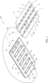
- Fig. 1 shows a schematic view of a protection assembly 1 in a decoupled state according to an embodiment of the invention.
- Fig. 2 shows a protection assembly 1 in a coupled state according to an embodiment of the invention from a top view perspective. In this top view perspective, a base sheet 11 of a bottom cover 10 is omitted only to illustrate the coupling when viewed from this perspective.
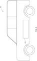
- Fig. 3 shows a protection assembly 1 in a coupled state according to an embodiment of the invention from a bottom view perspective. In this bottom view perspective, a base sheet 31 of the protection member 30 is omitted only to illustrate the coupling when viewed from this perspective.
- Fig. 4 shows a schematic cross section A as indicated in Figure 2 of the protection assembly 1 in a coupled state according to an embodiment of the present invention including the base sheet 11 of the bottom cover 10 and the base sheet 3 of the protection member 30.
- Fig. 1 shows a protection assembly 1 for protecting the bottom of a battery or battery system.
- the protection assembly 1 is shown in the decoupled state, while in the Figs. 2-4 the protection assembly 1 is viewed in the coupled state from different perspectives and/or cross sections.
- the coupled state between the protection member 30 and the bottom cover 10 is illustrated by a schematic connecting arrow. It is further indicated that the coupled state may be reached by a flip such that coupling members face each other as illustrated further below, for example in Fig. 4 .
- the protection assembly 1 comprises a bottom cover 10.
- the bottom cover 10 is part of a battery housing 100. Only for brevity purposes, further parts of the battery housing 100 may be omitted here. For example, here not shown, a plurality of battery components, in particular battery cells 110 and/or battery modules, a battery pack, control electronics, interfaces, a fuse etc. may be disposed on the bottom cover 10 and/or accommodated by the battery housing 100.
- the bottom cover 10 may comprise a base sheet 11, e.g. a planar sheet, which forms the base substrate of the bottom cover 10.
- the bottom cover 10 may for example comprise a plastic material, but the invention is not restricted thereto.
- the protection assembly 1 further comprises a protection member 30.
- the protection member 30 is provided separately from the bottom cover 10 in the uncoupled state as shown in Fig. 1 .
- Figs. 2 to 4 show the protection assembly 1, when the bottom cover 10 and the protection member 30 are in the coupled state.
- the protection member 30 is positioned below the bottom cover 10.
- the protection member 30 may comprise a base sheet 31, i.e. a planar sheet. It is noted here again that in Fig. 2 the base sheet 11 of the bottom cover 10 is omitted to illustrate the coupling when viewed from the top view perspective.
- the material of the base sheet 31 may be selected to provide stiffness and be suitable to absorb the exerted loads acting on the protection member 30. Preferably, steal is used as material. Therefore, the protection member 30 may protect the bottom of the battery from damage and/or deformation due to imposed static and dynamic loads.
- the bottom cover 10 comprises a plurality of first coupling members, in Fig. 1 illustrated by reference sign 14.
- the plurality of first coupling members is formed on a first surface 12 of the bottom cover 10.
- the first coupling members may be individually, i.e. independently or separately, provided from each other as illustrated in Fig. 1 and also in the Figs. 2 to 4 .
- the protection member 30 comprises a plurality of second coupling members, in Fig. 1 illustrated by reference sign 34.
- the plurality of second coupling members is formed on a second surface 32 of the protection member 30.
- the second coupling members may be individually provided from each other as illustrated in Fig. 1 and also in the Figs. 2 to 4 , i.e. they may be spatially separated from each other.
- the invention allows to assemble the protection member 30 to the bottom cover 10 by a lateral motion.
- Such assembling reached by the coupling members saves vertical space, in particular when the protection assembly 1 is placed in an underbody of a vehicle. Further, the assembling of the bottom cover 10 and the protection member 30 is conveniently fast and does not require an advanced tool set.
- the flaps 14 are formed in first cross members 20.
- the openings 34 are formed in second cross members 40, see Fig. 1 or Fig. 2 .
- the cross members 20, 40 may be made of metal, in particular of steel to provide impact absorbance.
- the first and second cross members 20, 40 may extend perpendicular to each other in the coupled state. This can be seen, for example, in Fig. 2 .
- the cross members 20, 40 may absorb impact forces and may provide the openings 34 and the flaps 14. Due to the perpendicular array of cross members crossing each other, higher stability and impact absorbance may be generated by this structure.
Landscapes
- Engineering & Computer Science (AREA)
- Chemical & Material Sciences (AREA)
- Mechanical Engineering (AREA)
- Transportation (AREA)
- Chemical Kinetics & Catalysis (AREA)
- Electrochemistry (AREA)
- General Chemical & Material Sciences (AREA)
- Combustion & Propulsion (AREA)
- Life Sciences & Earth Sciences (AREA)
- Sustainable Development (AREA)
- Sustainable Energy (AREA)
- Power Engineering (AREA)
- Manufacturing & Machinery (AREA)
- Aviation & Aerospace Engineering (AREA)
- Battery Mounting, Suspending (AREA)
Claims (12)
- Batteriegehäuse (100), umfassend:- eine untere Abdeckung (10);- ein Schutzelement (30), das sich in einem gekoppelten Zustand unter der unteren Abdeckung (10) befindet;wobei die untere Abdeckung (10) eine Mehrzahl von ersten Kopplungselementen umfasst, die auf einer ersten Fläche (12) der unteren Abdeckung (10) ausgebildet sind, und das Schutzelement (30) eine Mehrzahl von zweiten Kopplungselementen, die auf einer zweiten Fläche (32) des Schutzelements (30) ausgebildet sind, umfasst, wobei die erste und zweite Fläche (12, 32) einander in dem gekoppelten Zustand zugewandt sind, und die ersten und zweiten Kopplungselemente dazu ausgelegt sind, dass das Schutzelement (30) mechanisch mit der unteren Abdeckung (10) gekoppelt wird, indem das Schutzelement (30) in einer ersten Richtung (D1) entlang der unteren Abdeckung (10) verschoben wird, bis jedes der zweiten Kopplungselemente mit entsprechenden ersten Kopplungselementen in Eingriff kommt;dadurch gekennzeichnet, dass;eines von den ersten Kopplungselementen und den zweiten Kopplungselementen Öffnungen (34) umfasst und das andere von den ersten Kopplungselementen und den zweiten Kopplungselementen Klappen (14) umfasst, wobei jede Klappe (14) im gekoppelten Zustand mit einer entsprechenden Öffnung (34) in Eingriff steht;wobei die Klappen (14) in ersten Querträgern (20) ausgebildet sind und die Öffnungen (34) in zweiten Querträgern (40) ausgebildet sind, unddie ersten Querträger (20) und die zweiten Querträger (40) Hohlprofile umfassen.
- Batteriegehäuse (100) nach Anspruch 1, wobei die ersten und die zweiten Kopplungselemente derart ausgelegt sind, dass das Schutzelement (30) mechanisch von der unteren Abdeckung (10) entkoppelt wird, indem das Schutzelement (30) in einer zweiten Richtung (D2) entgegengesetzt zur ersten Richtung (D1) entlang der unteren Abdeckung (10) verschoben wird.
- Batteriegehäuse (100) nach einem der Ansprüche 1 bis 2, wobei die Öffnungen (34) in einer oder mehreren parallelen Reihen (R1, R2, R3) und die Klappen (14) in einer gleichen Anzahl von parallelen Reihen (L1, L2, L3) angeordnet sind, wobei sich die Reihen (R1, R2, R3; L1, L2, L3) im gekoppelten Zustand gegenseitig überlappen.
- Schutzanordnung (1) nach einem der Ansprüche 3 bis 4, wobei sich die ersten Querträger (20) und die zweiten Querträger (40) im gekoppelten Zustand senkrecht zueinander erstrecken.
- Batteriegehäuse (100) nach einem der Ansprüche 1 bis 4, wobei die zweiten Querträger (40) Kontaktabschnitte (42), die mit der entsprechenden Fläche (32) verbunden sind, und einen vorstehenden Abschnitt (44) umfassen, der das Hohlprofil bildet, wobei die Öffnung (34) in den vorstehenden Abschnitten (44) derart ausgebildet ist, dass die entsprechende Klappe (14) durch die Öffnung (34) hindurchgeht und der vorstehende Abschnitt (44) im gekoppelten Zustand mit der Klappe (14) überlappt.
- Batteriegehäuse (100) nach Anspruch 5, wobei der vorstehende Abschnitt (44) einen ebenen Abschnitt (45) umfasst, der parallel zu der entsprechenden Fläche (32) verläuft, wobei die Klappe (14) dazu ausgebildet ist, mit dem ebenen Abschnitt (45) derart in Kontakt zu stehen, dass sich zumindest ein Teil der Klappe (14) im gekoppelten Zustand zwischen dem ebenen Abschnitt (45) und der entsprechenden Fläche (32) befindet.
- Batteriegehäuse (100) nach einem der Ansprüche 1 bis 6, wobei die Klappen (14) in dem ersten Querträger (20) dazu ausgebildet sind, einen abgestuften Abschnitt (24) und einen ebenen Abschnitt (25), der mit dem abgestuften Abschnitt (24) verbunden ist, zu umfassen, wobei der ebene Abschnitt (25) eine offene Seite (26) gegenüber dem abgestuften Abschnitt (24) umfasst.
- Batteriegehäuse (100) nach Anspruch 7, wobei die ersten Querträger (20) einen Versatz (OF) umfassen, der zwischen der offenen Seite (26) des ebenen Abschnitts (25) und einem Basisabschnitt (22) des ersten Querträgers (20) ausgebildet ist.
- Batteriegehäuse (100) nach Anspruch 8, wobei der vorstehende Abschnitt (44) des zweiten Querträgers (40) durch den Versatz (OF) hindurchgeht, um im gekoppelten Zustand mit der Klappe (14) zu überlappen.
- Batteriegehäuse (100) nach einem der Ansprüche 1 bis 9, wobei der erste Querträger (20) mit der unteren Abdeckung (10) verschweißt ist und der zweite Querträger (40) mit dem Schutzelement (30) verschweißt ist.
- Batteriesystem, umfassend ein Batteriegehäuse (100) nach einem der Ansprüche 1 bis 10.
- Fahrzeug (300), umfassend ein Batteriesystem nach Anspruch 11, das in einem Unterboden des Fahrzeugs (300) angeordnet ist.
Priority Applications (6)
| Application Number | Priority Date | Filing Date | Title |
|---|---|---|---|
| EP21154717.9A EP4037083B1 (de) | 2021-02-02 | 2021-02-02 | Schutzanordnung und batteriegehäuse damit |
| HUE21154717A HUE068285T2 (hu) | 2021-02-02 | 2021-02-02 | Védõszerelés és az azt tartalmazó akkumulátorház |
| PL21154717.9T PL4037083T3 (pl) | 2021-02-02 | 2021-02-02 | Zespół zabezpieczający i obudowa baterii zawierająca taki zespół |
| KR1020220012707A KR20220111667A (ko) | 2021-02-02 | 2022-01-27 | 보호 어셈블리 및 이를 포함하는 전지 하우징 |
| CN202210105567.XA CN114843687B (zh) | 2021-02-02 | 2022-01-28 | 保护组件以及包括该保护组件的电池壳体 |
| US17/588,021 US12134311B2 (en) | 2021-02-02 | 2022-01-28 | Protection assembly and battery housing comprising the same |
Applications Claiming Priority (1)
| Application Number | Priority Date | Filing Date | Title |
|---|---|---|---|
| EP21154717.9A EP4037083B1 (de) | 2021-02-02 | 2021-02-02 | Schutzanordnung und batteriegehäuse damit |
Publications (2)
| Publication Number | Publication Date |
|---|---|
| EP4037083A1 EP4037083A1 (de) | 2022-08-03 |
| EP4037083B1 true EP4037083B1 (de) | 2024-07-03 |
Family
ID=74505064
Family Applications (1)
| Application Number | Title | Priority Date | Filing Date |
|---|---|---|---|
| EP21154717.9A Active EP4037083B1 (de) | 2021-02-02 | 2021-02-02 | Schutzanordnung und batteriegehäuse damit |
Country Status (4)
| Country | Link |
|---|---|
| EP (1) | EP4037083B1 (de) |
| KR (1) | KR20220111667A (de) |
| HU (1) | HUE068285T2 (de) |
| PL (1) | PL4037083T3 (de) |
Families Citing this family (2)
| Publication number | Priority date | Publication date | Assignee | Title |
|---|---|---|---|---|
| CN119682518B (zh) * | 2025-01-27 | 2025-09-26 | 中建五局第三建设有限公司 | 一种电池保护装置及电池防护方法 |
| CN120261888B (zh) * | 2025-06-03 | 2025-09-19 | 宁德时代新能源科技股份有限公司 | 电池装置和用电装置 |
Citations (2)
| Publication number | Priority date | Publication date | Assignee | Title |
|---|---|---|---|---|
| DE102011003535A1 (de) * | 2011-02-02 | 2012-08-02 | Behr Gmbh & Co. Kg | Verspannungsvorrichtungen |
| US20170288185A1 (en) * | 2016-03-02 | 2017-10-05 | Ford Global Technologies, Llc | Battery pack securing method |
Family Cites Families (3)
| Publication number | Priority date | Publication date | Assignee | Title |
|---|---|---|---|---|
| US7504176B2 (en) * | 2003-07-11 | 2009-03-17 | Arris International, Inc. | Capturing mechanism with a flexible tongue having guidetabs comprising hooks |
| CN207587788U (zh) * | 2017-06-01 | 2018-07-06 | 深圳市威誉特通讯设备有限公司 | 抽拉式汽车电池箱 |
| CN209395571U (zh) * | 2019-01-16 | 2019-09-17 | 湖南海博瑞德电智控制技术有限公司 | 一种新能源电动汽车动力电池包系统总成 |
-
2021
- 2021-02-02 EP EP21154717.9A patent/EP4037083B1/de active Active
- 2021-02-02 PL PL21154717.9T patent/PL4037083T3/pl unknown
- 2021-02-02 HU HUE21154717A patent/HUE068285T2/hu unknown
-
2022
- 2022-01-27 KR KR1020220012707A patent/KR20220111667A/ko active Pending
Patent Citations (2)
| Publication number | Priority date | Publication date | Assignee | Title |
|---|---|---|---|---|
| DE102011003535A1 (de) * | 2011-02-02 | 2012-08-02 | Behr Gmbh & Co. Kg | Verspannungsvorrichtungen |
| US20170288185A1 (en) * | 2016-03-02 | 2017-10-05 | Ford Global Technologies, Llc | Battery pack securing method |
Also Published As
| Publication number | Publication date |
|---|---|
| KR20220111667A (ko) | 2022-08-09 |
| EP4037083A1 (de) | 2022-08-03 |
| HUE068285T2 (hu) | 2024-12-28 |
| PL4037083T3 (pl) | 2024-12-02 |
Similar Documents
| Publication | Publication Date | Title |
|---|---|---|
| RU2684972C1 (ru) | Конструкция для установки аккумуляторной батареи | |
| EP3883007A1 (de) | Batteriemodul, verfahren zur montage eines batteriemoduls und fahrzeug mit einem batteriesatz mit mindestens einem batteriemodul | |
| EP3855526B1 (de) | Stromversorgungsvorrichtung, mit stromversorgungsvorrichtung ausgerüstetes fahrzeug und stromspeichervorrichtung | |
| EP4170788B1 (de) | Batterierahmen, batteriepack, elektrofahrzeug, verfahren zur montage eines batterierahmens und verfahren zur montage eines batteriepacks | |
| US20230123420A1 (en) | Battery frame, battery pack, electric vehicle, method of assembling a battery frame, and method of assembling a battery pack | |
| US12531306B2 (en) | Power supply device, electric vehicle using same, and power storage device | |
| US11605859B2 (en) | Battery module and vehicle equipped with same | |
| WO2021199594A1 (ja) | 電源装置及びこれを備える車両並びに蓄電装置 | |
| EP4037083B1 (de) | Schutzanordnung und batteriegehäuse damit | |
| US20240170786A1 (en) | Battery module, battery pack, and vehicle | |
| US12134311B2 (en) | Protection assembly and battery housing comprising the same | |
| US20250286201A1 (en) | Electricity storage device | |
| WO2021199596A1 (ja) | 電源装置及びこれを備える車両並びに蓄電装置 | |
| CN113451633B (zh) | 电池单元的堆叠及其组装方法、电池模块和车辆 | |
| US20250385358A1 (en) | Battery cell stack assembly a battery pack a battery module a vehicle and a method | |
| US12341211B2 (en) | Lateral battery bracket comprising two semi products | |
| US20250300313A1 (en) | Electric storage device | |
| EP4614706A1 (de) | Batteriesystem und verfahren zur montage und verfahren zur demontage des batteriesystems | |
| US20240322323A1 (en) | Power storage device | |
| US20230344037A1 (en) | Battery module having a housing with coolant jackets | |
| EP4187701B1 (de) | Seitliche batteriehalterung mit zwei halbzeugen | |
| US20250391987A1 (en) | Traction battery pack cell stack divider assembly | |
| US20250158202A1 (en) | Battery module arrangement, a battery pack, and a vehicle | |
| US20230121830A1 (en) | Battery module, a battery pack, an electric vehicle, a cell carrier, a cell assembly | |
| EP3852163B1 (de) | Gehäuse, batteriesystem und verfahren zur herstellung eines gehäuses |
Legal Events
| Date | Code | Title | Description |
|---|---|---|---|
| PUAI | Public reference made under article 153(3) epc to a published international application that has entered the european phase |
Free format text: ORIGINAL CODE: 0009012 |
|
| STAA | Information on the status of an ep patent application or granted ep patent |
Free format text: STATUS: REQUEST FOR EXAMINATION WAS MADE |
|
| 17P | Request for examination filed |
Effective date: 20220215 |
|
| AK | Designated contracting states |
Kind code of ref document: A1 Designated state(s): AL AT BE BG CH CY CZ DE DK EE ES FI FR GB GR HR HU IE IS IT LI LT LU LV MC MK MT NL NO PL PT RO RS SE SI SK SM TR |
|
| STAA | Information on the status of an ep patent application or granted ep patent |
Free format text: STATUS: EXAMINATION IS IN PROGRESS |
|
| 17Q | First examination report despatched |
Effective date: 20230728 |
|
| GRAP | Despatch of communication of intention to grant a patent |
Free format text: ORIGINAL CODE: EPIDOSNIGR1 |
|
| STAA | Information on the status of an ep patent application or granted ep patent |
Free format text: STATUS: GRANT OF PATENT IS INTENDED |
|
| INTG | Intention to grant announced |
Effective date: 20240201 |
|
| GRAS | Grant fee paid |
Free format text: ORIGINAL CODE: EPIDOSNIGR3 |
|
| GRAA | (expected) grant |
Free format text: ORIGINAL CODE: 0009210 |
|
| STAA | Information on the status of an ep patent application or granted ep patent |
Free format text: STATUS: THE PATENT HAS BEEN GRANTED |
|
| AK | Designated contracting states |
Kind code of ref document: B1 Designated state(s): AL AT BE BG CH CY CZ DE DK EE ES FI FR GB GR HR HU IE IS IT LI LT LU LV MC MK MT NL NO PL PT RO RS SE SI SK SM TR |
|
| REG | Reference to a national code |
Ref country code: CH Ref legal event code: EP |
|
| REG | Reference to a national code |
Ref country code: DE Ref legal event code: R096 Ref document number: 602021014984 Country of ref document: DE |
|
| REG | Reference to a national code |
Ref country code: SE Ref legal event code: TRGR |
|
| REG | Reference to a national code |
Ref country code: LT Ref legal event code: MG9D |
|
| REG | Reference to a national code |
Ref country code: NL Ref legal event code: MP Effective date: 20240703 |
|
| PG25 | Lapsed in a contracting state [announced via postgrant information from national office to epo] |
Ref country code: PT Free format text: LAPSE BECAUSE OF FAILURE TO SUBMIT A TRANSLATION OF THE DESCRIPTION OR TO PAY THE FEE WITHIN THE PRESCRIBED TIME-LIMIT Effective date: 20241104 |
|
| PG25 | Lapsed in a contracting state [announced via postgrant information from national office to epo] |
Ref country code: NL Free format text: LAPSE BECAUSE OF FAILURE TO SUBMIT A TRANSLATION OF THE DESCRIPTION OR TO PAY THE FEE WITHIN THE PRESCRIBED TIME-LIMIT Effective date: 20240703 |
|
| REG | Reference to a national code |
Ref country code: HU Ref legal event code: AG4A Ref document number: E068285 Country of ref document: HU |
|
| PG25 | Lapsed in a contracting state [announced via postgrant information from national office to epo] |
Ref country code: PT Free format text: LAPSE BECAUSE OF FAILURE TO SUBMIT A TRANSLATION OF THE DESCRIPTION OR TO PAY THE FEE WITHIN THE PRESCRIBED TIME-LIMIT Effective date: 20241104 Ref country code: NL Free format text: LAPSE BECAUSE OF FAILURE TO SUBMIT A TRANSLATION OF THE DESCRIPTION OR TO PAY THE FEE WITHIN THE PRESCRIBED TIME-LIMIT Effective date: 20240703 |
|
| PG25 | Lapsed in a contracting state [announced via postgrant information from national office to epo] |
Ref country code: NO Free format text: LAPSE BECAUSE OF FAILURE TO SUBMIT A TRANSLATION OF THE DESCRIPTION OR TO PAY THE FEE WITHIN THE PRESCRIBED TIME-LIMIT Effective date: 20241003 |
|
| PG25 | Lapsed in a contracting state [announced via postgrant information from national office to epo] |
Ref country code: GR Free format text: LAPSE BECAUSE OF FAILURE TO SUBMIT A TRANSLATION OF THE DESCRIPTION OR TO PAY THE FEE WITHIN THE PRESCRIBED TIME-LIMIT Effective date: 20241004 Ref country code: FI Free format text: LAPSE BECAUSE OF FAILURE TO SUBMIT A TRANSLATION OF THE DESCRIPTION OR TO PAY THE FEE WITHIN THE PRESCRIBED TIME-LIMIT Effective date: 20240703 |
|
| PG25 | Lapsed in a contracting state [announced via postgrant information from national office to epo] |
Ref country code: BG Free format text: LAPSE BECAUSE OF FAILURE TO SUBMIT A TRANSLATION OF THE DESCRIPTION OR TO PAY THE FEE WITHIN THE PRESCRIBED TIME-LIMIT Effective date: 20240703 |
|
| PG25 | Lapsed in a contracting state [announced via postgrant information from national office to epo] |
Ref country code: LV Free format text: LAPSE BECAUSE OF FAILURE TO SUBMIT A TRANSLATION OF THE DESCRIPTION OR TO PAY THE FEE WITHIN THE PRESCRIBED TIME-LIMIT Effective date: 20240703 |
|
| PG25 | Lapsed in a contracting state [announced via postgrant information from national office to epo] |
Ref country code: IS Free format text: LAPSE BECAUSE OF FAILURE TO SUBMIT A TRANSLATION OF THE DESCRIPTION OR TO PAY THE FEE WITHIN THE PRESCRIBED TIME-LIMIT Effective date: 20241103 |
|
| PG25 | Lapsed in a contracting state [announced via postgrant information from national office to epo] |
Ref country code: CZ Free format text: LAPSE BECAUSE OF FAILURE TO SUBMIT A TRANSLATION OF THE DESCRIPTION OR TO PAY THE FEE WITHIN THE PRESCRIBED TIME-LIMIT Effective date: 20240703 Ref country code: HR Free format text: LAPSE BECAUSE OF FAILURE TO SUBMIT A TRANSLATION OF THE DESCRIPTION OR TO PAY THE FEE WITHIN THE PRESCRIBED TIME-LIMIT Effective date: 20240703 |
|
| PG25 | Lapsed in a contracting state [announced via postgrant information from national office to epo] |
Ref country code: RS Free format text: LAPSE BECAUSE OF FAILURE TO SUBMIT A TRANSLATION OF THE DESCRIPTION OR TO PAY THE FEE WITHIN THE PRESCRIBED TIME-LIMIT Effective date: 20241003 Ref country code: ES Free format text: LAPSE BECAUSE OF FAILURE TO SUBMIT A TRANSLATION OF THE DESCRIPTION OR TO PAY THE FEE WITHIN THE PRESCRIBED TIME-LIMIT Effective date: 20240703 |
|
| PG25 | Lapsed in a contracting state [announced via postgrant information from national office to epo] |
Ref country code: RS Free format text: LAPSE BECAUSE OF FAILURE TO SUBMIT A TRANSLATION OF THE DESCRIPTION OR TO PAY THE FEE WITHIN THE PRESCRIBED TIME-LIMIT Effective date: 20241003 Ref country code: NO Free format text: LAPSE BECAUSE OF FAILURE TO SUBMIT A TRANSLATION OF THE DESCRIPTION OR TO PAY THE FEE WITHIN THE PRESCRIBED TIME-LIMIT Effective date: 20241003 Ref country code: LV Free format text: LAPSE BECAUSE OF FAILURE TO SUBMIT A TRANSLATION OF THE DESCRIPTION OR TO PAY THE FEE WITHIN THE PRESCRIBED TIME-LIMIT Effective date: 20240703 Ref country code: IS Free format text: LAPSE BECAUSE OF FAILURE TO SUBMIT A TRANSLATION OF THE DESCRIPTION OR TO PAY THE FEE WITHIN THE PRESCRIBED TIME-LIMIT Effective date: 20241103 Ref country code: HR Free format text: LAPSE BECAUSE OF FAILURE TO SUBMIT A TRANSLATION OF THE DESCRIPTION OR TO PAY THE FEE WITHIN THE PRESCRIBED TIME-LIMIT Effective date: 20240703 Ref country code: GR Free format text: LAPSE BECAUSE OF FAILURE TO SUBMIT A TRANSLATION OF THE DESCRIPTION OR TO PAY THE FEE WITHIN THE PRESCRIBED TIME-LIMIT Effective date: 20241004 Ref country code: FI Free format text: LAPSE BECAUSE OF FAILURE TO SUBMIT A TRANSLATION OF THE DESCRIPTION OR TO PAY THE FEE WITHIN THE PRESCRIBED TIME-LIMIT Effective date: 20240703 Ref country code: ES Free format text: LAPSE BECAUSE OF FAILURE TO SUBMIT A TRANSLATION OF THE DESCRIPTION OR TO PAY THE FEE WITHIN THE PRESCRIBED TIME-LIMIT Effective date: 20240703 Ref country code: CZ Free format text: LAPSE BECAUSE OF FAILURE TO SUBMIT A TRANSLATION OF THE DESCRIPTION OR TO PAY THE FEE WITHIN THE PRESCRIBED TIME-LIMIT Effective date: 20240703 Ref country code: BG Free format text: LAPSE BECAUSE OF FAILURE TO SUBMIT A TRANSLATION OF THE DESCRIPTION OR TO PAY THE FEE WITHIN THE PRESCRIBED TIME-LIMIT Effective date: 20240703 |
|
| PGFP | Annual fee paid to national office [announced via postgrant information from national office to epo] |
Ref country code: HU Payment date: 20250224 Year of fee payment: 5 |
|
| REG | Reference to a national code |
Ref country code: DE Ref legal event code: R097 Ref document number: 602021014984 Country of ref document: DE |
|
| PGFP | Annual fee paid to national office [announced via postgrant information from national office to epo] |
Ref country code: DE Payment date: 20250204 Year of fee payment: 5 |
|
| PG25 | Lapsed in a contracting state [announced via postgrant information from national office to epo] |
Ref country code: DK Free format text: LAPSE BECAUSE OF FAILURE TO SUBMIT A TRANSLATION OF THE DESCRIPTION OR TO PAY THE FEE WITHIN THE PRESCRIBED TIME-LIMIT Effective date: 20240703 Ref country code: SM Free format text: LAPSE BECAUSE OF FAILURE TO SUBMIT A TRANSLATION OF THE DESCRIPTION OR TO PAY THE FEE WITHIN THE PRESCRIBED TIME-LIMIT Effective date: 20240703 Ref country code: RO Free format text: LAPSE BECAUSE OF FAILURE TO SUBMIT A TRANSLATION OF THE DESCRIPTION OR TO PAY THE FEE WITHIN THE PRESCRIBED TIME-LIMIT Effective date: 20240703 |
|
| PGFP | Annual fee paid to national office [announced via postgrant information from national office to epo] |
Ref country code: SE Payment date: 20250211 Year of fee payment: 5 |
|
| PG25 | Lapsed in a contracting state [announced via postgrant information from national office to epo] |
Ref country code: EE Free format text: LAPSE BECAUSE OF FAILURE TO SUBMIT A TRANSLATION OF THE DESCRIPTION OR TO PAY THE FEE WITHIN THE PRESCRIBED TIME-LIMIT Effective date: 20240703 |
|
| PGFP | Annual fee paid to national office [announced via postgrant information from national office to epo] |
Ref country code: AT Payment date: 20250417 Year of fee payment: 5 |
|
| PGFP | Annual fee paid to national office [announced via postgrant information from national office to epo] |
Ref country code: FR Payment date: 20250210 Year of fee payment: 5 Ref country code: PL Payment date: 20250131 Year of fee payment: 5 |
|
| PG25 | Lapsed in a contracting state [announced via postgrant information from national office to epo] |
Ref country code: IT Free format text: LAPSE BECAUSE OF FAILURE TO SUBMIT A TRANSLATION OF THE DESCRIPTION OR TO PAY THE FEE WITHIN THE PRESCRIBED TIME-LIMIT Effective date: 20240703 Ref country code: SK Free format text: LAPSE BECAUSE OF FAILURE TO SUBMIT A TRANSLATION OF THE DESCRIPTION OR TO PAY THE FEE WITHIN THE PRESCRIBED TIME-LIMIT Effective date: 20240703 |
|
| PGFP | Annual fee paid to national office [announced via postgrant information from national office to epo] |
Ref country code: GB Payment date: 20250130 Year of fee payment: 5 |
|
| PLBE | No opposition filed within time limit |
Free format text: ORIGINAL CODE: 0009261 |
|
| STAA | Information on the status of an ep patent application or granted ep patent |
Free format text: STATUS: NO OPPOSITION FILED WITHIN TIME LIMIT |
|
| 26N | No opposition filed |
Effective date: 20250404 |
|
| PG25 | Lapsed in a contracting state [announced via postgrant information from national office to epo] |
Ref country code: MC Free format text: LAPSE BECAUSE OF FAILURE TO SUBMIT A TRANSLATION OF THE DESCRIPTION OR TO PAY THE FEE WITHIN THE PRESCRIBED TIME-LIMIT Effective date: 20240703 |
|
| REG | Reference to a national code |
Ref country code: CH Ref legal event code: PL |
|
| PG25 | Lapsed in a contracting state [announced via postgrant information from national office to epo] |
Ref country code: LU Free format text: LAPSE BECAUSE OF NON-PAYMENT OF DUE FEES Effective date: 20250202 |
|
| PG25 | Lapsed in a contracting state [announced via postgrant information from national office to epo] |
Ref country code: CH Free format text: LAPSE BECAUSE OF NON-PAYMENT OF DUE FEES Effective date: 20250228 |
|
| REG | Reference to a national code |
Ref country code: AT Ref legal event code: UEP Ref document number: 1700799 Country of ref document: AT Kind code of ref document: T Effective date: 20240703 |
|
| REG | Reference to a national code |
Ref country code: BE Ref legal event code: MM Effective date: 20250228 |
|
| PG25 | Lapsed in a contracting state [announced via postgrant information from national office to epo] |
Ref country code: BE Free format text: LAPSE BECAUSE OF NON-PAYMENT OF DUE FEES Effective date: 20250228 |
|
| PG25 | Lapsed in a contracting state [announced via postgrant information from national office to epo] |
Ref country code: IE Free format text: LAPSE BECAUSE OF NON-PAYMENT OF DUE FEES Effective date: 20250202 |