EP4036668A1 - Funktionelle sicherheitstechniken für industrielle automatisierungsvorrichtungen - Google Patents
Funktionelle sicherheitstechniken für industrielle automatisierungsvorrichtungen Download PDFInfo
- Publication number
- EP4036668A1 EP4036668A1 EP22151568.7A EP22151568A EP4036668A1 EP 4036668 A1 EP4036668 A1 EP 4036668A1 EP 22151568 A EP22151568 A EP 22151568A EP 4036668 A1 EP4036668 A1 EP 4036668A1
- Authority
- EP
- European Patent Office
- Prior art keywords
- circuitry
- power
- driver
- controller
- power module
- Prior art date
- Legal status (The legal status is an assumption and is not a legal conclusion. Google has not performed a legal analysis and makes no representation as to the accuracy of the status listed.)
- Granted
Links
Images


Classifications
-
- G—PHYSICS
- G05—CONTROLLING; REGULATING
- G05B—CONTROL OR REGULATING SYSTEMS IN GENERAL; FUNCTIONAL ELEMENTS OF SUCH SYSTEMS; MONITORING OR TESTING ARRANGEMENTS FOR SUCH SYSTEMS OR ELEMENTS
- G05B23/00—Testing or monitoring of control systems or parts thereof
- G05B23/02—Electric testing or monitoring
- G05B23/0205—Electric testing or monitoring by means of a monitoring system capable of detecting and responding to faults
- G05B23/0259—Electric testing or monitoring by means of a monitoring system capable of detecting and responding to faults characterized by the response to fault detection
- G05B23/0286—Modifications to the monitored process, e.g. stopping operation or adapting control
- G05B23/0291—Switching into safety or degraded mode, e.g. protection and supervision after failure
-
- H—ELECTRICITY
- H02—GENERATION; CONVERSION OR DISTRIBUTION OF ELECTRIC POWER
- H02H—EMERGENCY PROTECTIVE CIRCUIT ARRANGEMENTS
- H02H7/00—Emergency protective circuit arrangements specially adapted for specific types of electric machines or apparatus or for sectionalised protection of cable or line systems, and effecting automatic switching in the event of an undesired change from normal working conditions
- H02H7/20—Emergency protective circuit arrangements specially adapted for specific types of electric machines or apparatus or for sectionalised protection of cable or line systems, and effecting automatic switching in the event of an undesired change from normal working conditions for electronic equipment
-
- H—ELECTRICITY
- H02—GENERATION; CONVERSION OR DISTRIBUTION OF ELECTRIC POWER
- H02P—CONTROL OR REGULATION OF ELECTRIC MOTORS, ELECTRIC GENERATORS OR DYNAMO-ELECTRIC CONVERTERS; CONTROLLING TRANSFORMERS, REACTORS OR CHOKE COILS
- H02P27/00—Arrangements or methods for the control of AC motors characterised by the kind of supply voltage
- H02P27/04—Arrangements or methods for the control of AC motors characterised by the kind of supply voltage using variable-frequency supply voltage, e.g. inverter or converter supply voltage
- H02P27/06—Arrangements or methods for the control of AC motors characterised by the kind of supply voltage using variable-frequency supply voltage, e.g. inverter or converter supply voltage using DC to AC converters or inverters
-
- G—PHYSICS
- G05—CONTROLLING; REGULATING
- G05B—CONTROL OR REGULATING SYSTEMS IN GENERAL; FUNCTIONAL ELEMENTS OF SUCH SYSTEMS; MONITORING OR TESTING ARRANGEMENTS FOR SUCH SYSTEMS OR ELEMENTS
- G05B19/00—Program-control systems
- G05B19/02—Program-control systems electric
- G05B19/04—Program control other than numerical control, i.e. in sequence controllers or logic controllers
- G05B19/048—Monitoring; Safety
-
- G—PHYSICS
- G05—CONTROLLING; REGULATING
- G05B—CONTROL OR REGULATING SYSTEMS IN GENERAL; FUNCTIONAL ELEMENTS OF SUCH SYSTEMS; MONITORING OR TESTING ARRANGEMENTS FOR SUCH SYSTEMS OR ELEMENTS
- G05B19/00—Program-control systems
- G05B19/02—Program-control systems electric
- G05B19/04—Program control other than numerical control, i.e. in sequence controllers or logic controllers
- G05B19/05—Programmable logic controllers, e.g. simulating logic interconnections of signals according to ladder diagrams or function charts
- G05B19/058—Safety, monitoring
-
- H—ELECTRICITY
- H02—GENERATION; CONVERSION OR DISTRIBUTION OF ELECTRIC POWER
- H02H—EMERGENCY PROTECTIVE CIRCUIT ARRANGEMENTS
- H02H1/00—Details of emergency protective circuit arrangements
- H02H1/0092—Details of emergency protective circuit arrangements concerning the data processing means, e.g. expert systems, neural networks
-
- H—ELECTRICITY
- H02—GENERATION; CONVERSION OR DISTRIBUTION OF ELECTRIC POWER
- H02M—APPARATUS FOR CONVERSION BETWEEN AC AND AC, BETWEEN AC AND DC, OR BETWEEN DC AND DC, AND FOR USE WITH MAINS OR SIMILAR POWER SUPPLY SYSTEMS; CONVERSION OF DC OR AC INPUT POWER INTO SURGE OUTPUT POWER; CONTROL OR REGULATION THEREOF
- H02M1/00—Details of apparatus for conversion
- H02M1/08—Circuits specially adapted for the generation of control voltages for semiconductor devices incorporated in static converters
- H02M1/088—Circuits specially adapted for the generation of control voltages for semiconductor devices incorporated in static converters for the simultaneous control of series or parallel connected semiconductor devices
-
- G—PHYSICS
- G05—CONTROLLING; REGULATING
- G05B—CONTROL OR REGULATING SYSTEMS IN GENERAL; FUNCTIONAL ELEMENTS OF SUCH SYSTEMS; MONITORING OR TESTING ARRANGEMENTS FOR SUCH SYSTEMS OR ELEMENTS
- G05B2219/00—Program-control systems
- G05B2219/10—Plc systems
- G05B2219/14—Plc safety
- G05B2219/14116—Safe, emergency shutdown, esd of system
-
- G—PHYSICS
- G05—CONTROLLING; REGULATING
- G05B—CONTROL OR REGULATING SYSTEMS IN GENERAL; FUNCTIONAL ELEMENTS OF SUCH SYSTEMS; MONITORING OR TESTING ARRANGEMENTS FOR SUCH SYSTEMS OR ELEMENTS
- G05B2219/00—Program-control systems
- G05B2219/20—Pc systems
- G05B2219/24—Pc safety
- G05B2219/24125—Watchdog, check at timed intervals
-
- G—PHYSICS
- G05—CONTROLLING; REGULATING
- G05B—CONTROL OR REGULATING SYSTEMS IN GENERAL; FUNCTIONAL ELEMENTS OF SUCH SYSTEMS; MONITORING OR TESTING ARRANGEMENTS FOR SUCH SYSTEMS OR ELEMENTS
- G05B2219/00—Program-control systems
- G05B2219/20—Pc systems
- G05B2219/25—Pc structure of the system
- G05B2219/25158—Watchdog
Definitions
- the disclosure generally relates to controlling, monitoring, and disabling an industrial automation device. More particularly, embodiments of the present disclosure are related to systems and methods for implementing a functional safety mechanism to prevent power from being provided to an industrial automation device and verifying that circuitry used to implement the functional safety mechanism is functioning properly.
- Industrial automation devices such as medium voltage drives, are employed in a variety of environments. Under certain circumstances, these industrial automation devices are disabled and placed into a safe state. Accordingly, certain functional safety mechanisms may be designed to reliably disable the industrial automation devices under these circumstances.
- the design of such functional safety mechanisms may be designed to comply with certain functional safety standards, such as the International Electrotechnical Commission (IEC) 61508.
- IEC International Electrotechnical Commission
- One such functional safety mechanism involves the use of a Black Channel to send sophisticated safety messages between a controller of an industrial automation device and one or more power cells of the industrial automation device.
- implementation of a Black Channel may require the use of multiple intelligent devices, such as field-programmable gate arrays (FPGAs), in circuit board designs for the industrial automation device. This may lead to complex and expensive circuit board designs.
- FPGAs field-programmable gate arrays
- a non-transitory, computer-readable medium associated with an industrial automation device may include instructions that when executed by one or more processors, cause the processors to perform operations.
- the operations may include receiving one or more inputs indicative of a shutdown of one or more power modules of the industrial automation device.
- the operations may also include, in response to receiving the inputs, transmitting a first command to driver control circuitry to disable a driver communicatively coupled to one or more transmitters and transmitting a second command to transmitter control circuitry to prevent power from being provided to the transmitters.
- the driver may transmit a control signal via the transmitters to one or more respective power modules to control an operation of a power converter that may provide power to a motor.
- Each power module may receive the control signal from the driver via the transmitters, monitor the control signal for a lack of communication from the driver, and in response to detecting the lack of communication based on the control signal, disable driver circuitry of the power module that may control the operation of the power converter to provide power to the motor and prevent power from being provided to the driver circuitry.
- a method may include receiving, by respective processing circuitry of one or more power modules of an industrial automation device, a control signal from a controller of the industrial automation device.
- the power modules may include driver circuitry and a power converter that may provide power to a motor based on the signal.
- the method may also include, detecting, by the respective processing circuitry, a lack of communication from the controller based on the signal, and, in response to detecting the lack of communication from the controller, transmitting, by the respective processing circuitry, a first command to gating signal enable circuitry to disable the driver circuitry, and transmitting, by the respective processing circuitry, a second command to drive power circuitry to prevent power from being provided to the driver circuitry.
- a system may include a controller that includes a driver communicatively coupled to one or more transmitters and first processing circuitry.
- the driver may transmit a control signal via the transmitters to one or more respective power modules.
- the first processing circuitry may receive one or more inputs indicative of a shutdown of the respective power modules and, in response to receiving the inputs, transmitting a first command to driver control circuitry communicatively coupled to the driver and transmitting a second command to transmitter control circuitry communicatively coupled to the transmitter.
- the first command may disable the driver, and the second command may prevent power from being provided to the transmitters.
- the system may also include a power module that may control an operation of a power converter to provide power to a motor.
- the power module is communicatively coupled to a first transmitter.
- the power module includes driver circuitry that may control the operation of the power converter, and second processing circuitry that may receive the control signal from the first transmitter, detect a lack of communication from the controller based on the control signal, and, in response to detecting the lack of communication, transmit a third command to gating signal circuitry to disable the driver circuitry and transmit a fourth command to drive power circuitry to prevent power from being provided to the driver circuitry.
- Industrial automation devices such as medium voltage drives, are employed in a variety of environments. Under certain circumstances, these industrial automation devices may be disabled and placed into a safe state. Certain functional safety mechanisms may be designed to reliably disable the industrial automation devices.
- One such functional safety mechanism involves the use of a Black Channel to send sophisticated safety messages between a controller of an industrial automation device and one or more power cells of the industrial automation device to disable the industrial automation device.
- implementation of a Black Channel may involve the use of multiple intelligent devices, such as field-programmable gate arrays (FPGAs), in circuit board designs for the industrial automation device that may result in complex and expensive circuit board designs.
- development of the sophisticated safety messages may involve extensive work in order to meet the functional safety standards, such as IEC 61508. For example, code used to configure the intelligent devices in the circuit board design may need to be validated before implementation.
- the present disclosure is generally directed to a functional safety mechanism for an industrial automation device that may stop a communication stream between the controller of the industrial automation device and one or more power modules of the industrial automation device in order to disable the industrial automation device (e.g., place the power modules of the industrial automation device in a safe state).
- the industrial automation device may include a medium voltage drive having a controller and one or more power modules that may control the operation of one or more corresponding power converters to provide power to a motor.
- the functional safety mechanism may be used with other industrial automation devices.
- the industrial automation devices may include a low voltage drive (e.g., supply voltages below 2.3 kV), a high voltage drive (e.g., supply voltages above 11 kV), a multi-axis motion servo drive, a current source drive, or any other industrial automation device that may utilize a communication stream and may be placed in a functionally safe state without using dedicated safety messages.
- the controller of the medium voltage drive may transmit one or more messages (e.g., data or command(s)) via a serial-based communications link to the power modules(s) of the medium voltage drive.
- the power module(s) may control the operation of one or more corresponding power converters to provide power to the motor based on the particular messages received.
- the controller of the medium voltage drive may trigger a functional safety mechanism to place the power module(s) in a safe state.
- the controller of the medium voltage drive may receive a command to initiate the functional safety mechanism from various devices communicatively coupled to the controller, such as an e-stop button, a programmable logic controller (PLC), a light curtain, or the like.
- PLC programmable logic controller
- the controller of the medium voltage drive may (1) disable respective transmitters (e.g., turn off power to the transmitters) that relay the messages between the controller and the power module(s) and (2) disable generation of gating signals (e.g., enabling signals) that would control a driver of the controller to transmit one or more messages to the respective transmitters to relay the messages to the power module(s)
- respective transmitters e.g., turn off power to the transmitters
- gating signals e.g., enabling signals
- each power module may include communication monitoring circuitry, such as a communication watchdog timer, that monitors for gaps in communication (e.g., a period of time lacking message transmission) from the controller.
- the power module may (1) disable driver circuitry of the power module (e.g., turn off power to the driver circuitry) that may generate one or more signals to control an operation of one or more corresponding power converters that provide power to the motor and (2) disable generation of one or more gating signals (e.g., one or more enabling signals) that would control the driver circuitry of the power module to generate the signals to control the operation of the corresponding power converter to provide power to the motor.
- the power module of the medium voltage drive may be disabled and placed in a safe state.
- the functional safety mechanism provides multiple levels of redundancy by implementing different methods to prevent the transmission of signals from the controller to the power module(s) and different methods to prevent power from being provided to the motor. That is, to prevent the transmission of signals from the controller to the power module(s), the controller of the medium voltage drive may (1) disable the transmitters (e.g., turn off power to the transmitters) and (2) disable generation of the gating signals (e.g., the enabling signals) that would control the driver of the controller to transmit one or more messages to the respective transmitters to relay the messages to the power module(s).
- the controller of the medium voltage drive may (1) disable the transmitters (e.g., turn off power to the transmitters) and (2) disable generation of the gating signals (e.g., the enabling signals) that would control the driver of the controller to transmit one or more messages to the respective transmitters to relay the messages to the power module(s).
- the power module may (1) disable the driver circuitry of the power module (e.g., turn off power to the driver circuitry) and (2) disable generation of the gating signals (e.g., the enabling signals) that would control the driver circuitry of the power module to generate the signals to control the operation of the corresponding power converter to provide power to the motor.
- the driver circuitry of the power module e.g., turn off power to the driver circuitry
- the gating signals e.g., the enabling signals
- one or more diagnostic tests may be implemented within the medium voltage drives to verify the integrity of the circuitry that may be used to implement the functional safety mechanism in the controller of the medium voltage drive, in each power module of the medium voltage drive, or a combination thereof.
- a short test pulse (e.g., less than 100 nanoseconds) may be transmitted to one or more components of the controller of the medium voltage drive (e.g., transmitter control circuitry), one or more components of the power module(s) of the medium voltage drive (e.g., the driver control circuitry), or a combination thereof, to verify the integrity or the ability of whether such components can power down respective circuitry of the controller and the power module(s) when requested.
- the controller of the medium voltage drive may receive data that indicates whether the diagnostic tests of the respective components of the controller or the power module(s) were successful. If the data indicates a diagnostic test was unsuccessful, the controller may initiate the functional safety mechanism described herein.
- FIG. 1 is a block diagram 100 of a medium voltage drive 102 that includes a controller 104 and one or more power module(s) 106 that may control the operation of one or more corresponding power converters 108 to provide power to a motor 110.
- each power converter 108 may receive three-phase alternating current (AC) voltage from a voltage source 112 or a direct current (DC) voltage from the voltage source 112 and convert the AC voltage or DC voltage into a voltage suitable for powering a load.
- the power converter 108 may supply a voltage source 112 to the motor 110 via one or more inverters.
- the medium voltage drive 102 may control the speed, torque, or other suitable operation of the motor 110 by controlling characteristics of the voltage (e.g., amplitude or frequency) provided to the motor 110 via the inverters.
- the controller 104 of the medium voltage drive 102 may transmit one or more messages (e.g., data or command(s)) via a serial-based communications link to the power modules(s) 106 of the medium voltage drive 102 during normal operation of the medium voltage drive 102.
- the power module(s) 106 may generate one or more signals (e.g., pulse width modulation signals) to control the operation of the corresponding power converter(s) 108 to provide power to the motor 110 based on the particular messages received.
- the motor 110 may be coupled to and drive one or more fans, one or more pumps, one or more compressors, or the like.
- the controller 104 of the medium voltage drive 102 may receive a command to initiate a functional safety mechanism to shutdown the medium voltage drive 102.
- the term “shutdown” may refer to a situation in which the power module(s) 106 of the medium voltage drive 102 are placed in a safe state or turned off such that the power module(s) 106 are not generating signals to control their corresponding power converters to provide power to the motor 110.
- the controller 104 of the medium voltage drive 102 may receive the command to initiate the functional safety mechanism from various devices communicatively coupled to the controller 104 via a network.
- such devices may include an e-stop button, a programmable logic controller (PLC), a light curtain, or the like.
- the network may include any wired or wireless network that may be implemented as a local area network (LAN), a wide area network (WAN), and the like
- LAN local area network
- WAN wide area network
- other industrial communication network protocols such as Ethernet/IP, Common Industrial Protocol (CIP) Safety, ProfiSafe, and the like, may also be used.
- the controller 104 of the medium voltage drive 102 may send one or more respective commands to corresponding circuitry in the controller 104 of the medium voltage drive 102 to (1) disable one or more transmitters of the controller 104 that may relay messages between the controller 104 and the power module(s) 106 and (2) disable generation of gating signals (e.g., enabling signals) that would control a driver of the controller 104 to transmit one or more messages to the transmitters to relay the messages to the power module(s) 106.
- Each power module 106 may include communication monitoring circuitry that monitors for gaps in communication from the controller 104 to initiate the functional safety mechanism.
- the power module(s) 106 may initiate the functional safety mechanism in response to detecting a gap (e.g., a period of time lacking transmissions) in communication from the controller 104 to (1) disable driver circuitry of the power module 106 that may generate one or more signals (e.g., pulse width modulation signals) to control operation of a corresponding power converter to provide power to the motor 110 and (2) disable generation of gating signals (e.g., enabling signals) that would control the driver circuitry of the power module 106 to generate the signals to control the operation of the corresponding power converter.
- the time period of the gap in communication may be greater than or equal to 100 milliseconds.
- any suitable time period may be used to trigger the power module 106 to initiate the functional safety mechanism.
- the time period of the gap may be based on the transmission rate of data between the controller 104 and the power module(s) 106 and a required safety reaction time.
- the functional safety mechanism provides multiple levels of redundancy in disabling the medium voltage drive 102 by preventing messages from being transmitted from the controller 104 to the power module(s) 106 and preventing power from being provided to the motor 110.
- the medium voltage drive 102 may have up to twenty-seven, or more, power modules 106. However, it should be noted that the medium voltage drive 102 may have any suitable number of power modules 106 to deliver power to the motor 110 during normal operation of the medium voltage drive 102. Additionally, for each power module 106 of the medium voltage drive 102, the controller 104 may have a respective transmitter for transmitting messages from the controller 104 to a respective power module controller 107 that controls operation of its corresponding power converter 108 to provide power to the motor 110.
- the controller 104 may periodically initiate one or more diagnostic tests to verify the integrity (e.g., ability) or the operability of the circuitry that may be used to implement the functional safety mechanism in the controller 104 of the medium voltage drive 102, the circuitry that may be used to implement the functional safety mechanism in each power module 106 of the medium voltage drive 102, or a combination thereof.
- the controller 104 may initiate the diagnostic tests at 250 millisecond intervals, at 500 millisecond intervals, at one second intervals, or any other suitable interval.
- Each diagnostic test may include transmitting a test pulse to the circuitry of the controller 104 that may disable the transmitters of the controller 104, transmitting a test pulse to the circuitry of the controller 104 that may disable generation of enabling signals that would control the driver of the controller 104 to transmit the messages to the transmitters, transmitting a test pulse to the circuitry of the power module(s) 106 that may disable the driver circuitry of the power module 106 that generates one or more signals to control operation of a corresponding power converter to provide power to the motor 110, transmitting a test pulse to the circuitry of the power module(s) that may disable generation of the enabling signals that would control the driver circuitry of the power module 106 to generate the signals to control operation of the corresponding power converter, or a combination thereof.
- the test pulse may be less than or equal to 100 nanoseconds, less than or equal to 80 nanoseconds, less than or equal to 60 nanoseconds, or any other suitable length such that the diagnostic test may determine whether the circuitry of the controller 104 and/or the circuitry of the power module(s) may perform the functional safety mechanism but not trigger the functional safety mechanism. That is, the diagnostic tests of the circuitry of the controller 104 and the circuitry of the power module(s) 106 may be carried out while the medium voltage drive 102 continues to operate to provide power to the motor 110.
- the controller 104 may receive data indicative of the results of each diagnostic test If one or more of the diagnostic tests returns an unsuccessful result, the controller 104 may initiate the functional safety mechanism to place the power module(s) 106 of the medium voltage drive 102 in a safe state. For example, if a diagnostic test of one of the power modules 106 of the medium voltage drive 102 determines that the circuitry of the power module 106 is not able to (1) disable the driver circuitry of the power module 106 or (2) disable generation of the enabling signals that would control the driver circuitry of the power module 106, or both, the controller 104 may initiate the functional safety mechanism described herein to place each power module 106 in a safe state.
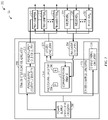
- FIG. 2 is block diagram 200 of the controller 104 of the medium voltage drive 102
- FIG. 3 is a block diagram 300 of a single power module 106 of the medium voltage drive 102
- the controller 104 may include processing circuitry 202 that includes a processor 204 and a memory 206.
- the processor 204 may be any suitable type of computer processor or microprocessor capable of executing computer-executable code, including but not limited to one or more field programmable gate arrays (FPGA), application-specific integrated circuits (ASIC), programmable logic devices (PLD), programmable logic arrays (PLA), and the like.
- the processor 204 may, in some embodiments, include multiple processors.
- the memory 206 may include any suitable articles of manufacture that serve as media to store processor-executable code, data, and the like.
- the memory 206 may store non-transitory processor-executable code used by the processor 204 to perform the presently disclosed techniques.
- the processing circuitry 202 of the controller 104 may generate one or more messages that may be transmitted to a driver 208 (e.g., driver circuitry 208) of the controller 104 to provide to one or more power module(s) 106 of the medium voltage drive 102 via one or more respective transmitters 210, 212, 214.
- the power module controller 107 may generate one or more signals to control operation of its corresponding power converter to provide power to the motor 110 based on the messages received from the controller 104.
- the processing circuitry 202 may include a communication engine 216 that generates the messages transmitted to the driver 208 based on data received by the processing circuitry 202 from one or more input sources.
- the input sources may include one or more sensors associated with the medium voltage drive 102, one or more sensors associated with the motor 110, one or more user inputs, or the like.
- the driver 208 of the controller 104 may transmit the messages to the power modules 106 via the transmitters 210, 212, 214.
- the communication engine 216 of the controller 104 may act as a buffer to temporarily store the messages as the driver 208 transmits the messages to the power module(s) 106 via the transmitters 210, 212, 214.
- the transmitters 210, 212, 214 may convert the messages (e.g., digital signals) received from the driver 208 into a format compatible with the power module(s) 106. In some embodiments, transmitters 210, 212, 214 may convert the messages into a fiber optic signal before the transmitters 210, 212, 214 relay the fiber optic signal to the power module(s) 106. Although three transmitters 210, 212, 214 are illustrated in FIG. 2 , it should be understood that any suitable number of transmitters 210, 212, 214 may be included in the controller 104. For instance, the number of transmitters 210, 212, 214 may correspond to the number of power module(s) 106 of the medium voltage drive 102. In this way, the controller 104 may individually control each power module 106 via a respective transmitter 210, 212, 214 of the controller 104.
- the controller 104 may individually control each power module 106 via a respective transmitter 210, 212, 214 of the controller 104.
- the power module controller 107 of the power module (106) may include processing circuitry 302 that may receive the messages from the controller 104 via a receiver 304.
- the receiver 304 may receive the messages as a fiber optic signal and convert the fiber optic signal into a digital signal that may be interpreted by the processing circuitry 302.
- the processing circuitry 302 of the power module controller 107 includes a processor 306 and a memory 308.
- the processor 306 may be any suitable type of computer processor or microprocessor capable of executing computer-executable code, including but not limited to one or more field programmable gate arrays (FPGA), application-specific integrated circuits (ASIC), programmable logic devices (PLD), programmable logic arrays (PLA), and the like.
- the processor 306 may, in some embodiments, include multiple processors.
- the memory 308 may include any suitable articles of manufacture that serve as media to store processor-executable code, data, and the like.
- the memory 308 may store non-transitory processor-executable code used by the processor 306 to perform the presently disclosed techniques.
- the processing circuitry 302 of the power module controller 107 may control the operation of its power converter 108 to provide power to the motor 110 based on the messages received from the controller 104.
- a communication engine 310 of the processing circuitry 302 may interpret the messages received from the controller 104 and send a command to driver circuitry 312 to generate one or more signals (e.g., pulse width modulation signals) to control the operation of its corresponding power converter 108 to provide power to the motor 110.
- the processing circuitry 202 of the controller 104 may receive a command to initiate the functional safety mechanism to shutdown the medium voltage drive 102.
- the processing circuitry 202 of the controller 104 may receive the command to initiate the functional safety mechanism from an e-stop button, a programmable logic controller (PLC), a light curtain, or the like.
- PLC programmable logic controller
- the processing circuitry 202 of the controller 104 may send one or more respective commands to corresponding circuitry of the controller 104 to (1) disable one or more transmitters 210, 212, 214 of the controller 104 that may relay messages between the controller 104 and the power module(s) 106 and (2) disable generation of enabling signals that would control the driver 208 of the controller 104 to transmit messages to the to the power module(s) 106 via the transmitters 210, 212, 214.
- the processing circuitry 202 of the controller 104 may send a first command to the transmitter control circuitry 218 to turn off the power provided to the transmitters 210, 212, 214.
- the processing circuitry 202 of the controller 104 may send a second command to the driver control circuitry 220 to disable the driver 208 in order to prevent messages from being transmitted from the driver 208 to the transmitters 210, 212, 214.
- the processing circuitry 202 of the controller 104 may send the first command to the transmitter control circuitry 218 and the second command to the driver control circuitry 220 at the substantially the same time or simultaneously.
- the transmitter control circuitry 218 and/or the driver control circuitry 220 may receive the command to initiate the functional safety mechanism directly (e.g., from the e-stop button, the PLC, the light curtain, or the like).
- the power module 106 may continuously monitor for gaps in communication from the controller 104 via communication monitoring circuitry 314 (e.g., a communication watchdog timer) in order to initiate the functional safety mechanism.
- the receiver 304 may send the messages (e.g., digital signal that includes the messages) from the controller 104 to the processing circuitry 302 and the communication monitoring circuitry 314.
- the communication monitoring circuitry 314 may detect a gap in communication from the controller 104 by analyzing the digital signal from the receiver 304.
- a sufficient time period of a gap in communication from the controller 104 to trigger the functional safety mechanism may be greater than or equal to 100 milliseconds.
- the power module 106 may monitor for a loss of communication (e.g., messages) from the controller 104 or an irregular frequency of communication transmission (e.g., an increase or a decrease in frequency of messages received) from the controller 104.
- the communication monitoring circuitry 314 may detect the loss of communication or the irregular frequency of communication transmission and trigger the functional safety mechanism.
- the communication monitoring circuitry 314 may transmit data indicative of the detected gap to the processing circuitry 302 of the power module 106.
- the processing circuitry 302 of the power module may then send one or more respective commands to corresponding circuitry of the power module 106 to (1) disable the driver circuitry 312 of the power module 106 and (2) disable generation of enabling signals that would control the driver circuitry 312 to generate and transmit one or more signals (e.g., pulse width modulation signals) to the corresponding power converter 108 to provide power to the motor 110.
- the processing circuitry 302 of the power module 106 may send a first command to the driver power circuitry 316 to turn off the power provided to the driver circuitry 312.
- the processing circuitry 302 of the power module 106 may send a second command to the gating control circuitry 318 to disable the driver circuitry 312 in order to prevent the driver circuitry 312 from generating and transmitting the signals to control operation of the corresponding power converter 108 to provide power to the motor 110.
- the power module 106 of the medium voltage drive 102 may be disabled and placed in a safe state.
- the processing circuitry 302 of the power module 106 may send the first command to the driver power circuitry 316 and the second command to the gating control circuitry 318 at the substantially the same time or simultaneously.
- the driver power circuitry 316 and/or the gating control circuitry 318 may receive a command to initiate the functional safety mechanism directly (e.g., from the communication monitoring circuitry 314 in response to detecting the gap).
- the controller 104 may periodically initiate one or more diagnostic tests (e.g., enable tests and power tests) to verify the integrity or the operability of the circuitry that may be used to implement the functional safety mechanism in the controller 104 of the medium voltage drive 102, the circuitry that may be used to implement the functional safety mechanism in each power module 106 of the medium voltage drive 102, or a combination thereof.
- the processing circuitry 202 of the controller 104 may periodically initiate a diagnostic test to determine whether the transmitter control circuitry 218 may successfully turn off the power provided to the transmitters 210, 212, 214.
- the processing circuitry 202 of the controller 104 may send a command to the transmitter control circuitry 218 to generate a test pulse via the power supply control circuitry 222 and provide the test pulse to the power supply hold circuitry 224.
- the transmitter control circuitry 218 may monitor whether the test pulse causes a disruption in the power signal provided to the transmitters 210, 212, 214.
- the power supply hold circuitry 224 provides a hold circuit that supplies an additional power signal (e.g., a functional safety power signal) to the transmitters 210, 212, 214 to maintain operation of the transmitters 210, 212, 214 while the diagnostic test is implemented.
- the functional safety power signal is distinct from the power signal through which the test pulse is transmitted from the power supply control circuitry 222 to the power supply hold circuitry 224. In this way, communication between the controller 104 and the power module(s) 106 is not disrupted during the diagnostic test of the transmitter control circuitry 218.
- the power supply hold circuitry 224 may include a pulse test-latch disposed in the power supply hold circuitry 224 before the hold circuit.
- the pulse test-latch may receive the test pulse from the power supply control circuitry 222 before it is transmitted to the hold circuit.
- a clock input of the pulse test-latch may switch to a logical one, thereby causing an output of the pulse test-latch switching to a logical zero.
- the hold circuit may then receive the test pulse from the pulse test-latch, which is detected, thereby, verifying the ability of the power supply hold circuitry 224 to turn off the power to the transmitters 210, 212, 214. It should be understood that the test pulse does not cause a disruption of the power signal from the hold circuit to the transmitters 210, 212, 214 because a capacitor in the hold circuit does not allow this test pulse through to the transmitters 210, 212, 214.
- the transmitter control circuitry 218 may send data indicative of a successful diagnostic test of the transmitter control circuitry 218 to the processing circuitry 202 of the controller 104.
- the processing circuitry 202 of the controller 104 may then store the successful diagnostic test result in the memory 206 However, if the pulse test-latch does not switch to a logical zero, the transmitter control circuitry 218 may send data indicative of an unsuccessful diagnostic test of the transmitter control circuitry 218 to the processing circuitry 202 of the controller 104. If the processing circuitry 202 of the controller 104 receives an unsuccessful diagnostic test result from the transmitter control circuitry 218, the processing circuitry 202 of the controller 104 may initiate the functional safety mechanism described herein.
- the processing circuitry 202 of the controller 104 may also periodically initiate a diagnostic test to determine whether the driver control circuitry 220 may successfully turn off generation of enabling signals that would control the driver 208 of the controller 104 to transmit messages to the transmitters 210, 212, 214 that relay the messages to the power module(s) 106. For instance, the processing circuitry 202 of the controller 104 may send a command to the driver control circuitry 220 to generate a test pulse to disable generation of the enabling signals of the driver 208 by the enable signal circuitry 226. The driver control circuitry 220 may monitor whether the test pulse causes a disruption in the enable signal of the enable signal circuitry 226.
- the enable signal circuitry 226 may include a pulse test-latch that receives the test pulse.
- a clock input of the pulse test-latch may switch to a logical one, thereby causing an output of the pulse test-latch switching to a logical zero.
- the driver control circuitry 220 may send a disabling signal to the driver 208 of the controller 104.
- the driver 208 may send a signal indicative of a successful shutdown to the driver control circuitry 220, which sends data indicative of a successful diagnostic test of the driver control circuitry 220 to the processing circuitry 202 of the controller 104. Additionally, the driver control circuitry 220 may send an enable signal to the driver 208 shortly after receiving the signal indicative of the successful shutdown of the driver 208. In this way, the driver 208 experiences a short shutdown such that the driver may be re-enabled before any loss of data being transmitted. The processing circuitry 202 of the controller 104 may then store the successful diagnostic test result in the memory 206.
- the driver 208 may send a signal indicative of an unsuccessful shutdown to the driver control circuitry 220, which sends data indicative of an unsuccessful diagnostic test to the processing circuitry 202 of the controller 104.
- the processing circuitry 202 of the controller 104 may initiate the functional safety mechanism described herein.
- the processing circuitry 302 of the power module(s) 106 may periodically initiate one or more diagnostic tests to determine whether the driver power circuitry 316 may successfully turn off the power provided to the driver circuitry 312. For instance, the processing circuitry 302 of the power module(s) may send a command to the driver power circuitry 316 to generate a test pulse via the power supply control circuitry 322 and provide the test pulse to the power supply hold circuitry 320. The driver power control circuitry 316 may monitor whether the test pulse causes a disruption in the power signal provided to the power supply hold circuitry 320.
- the power supply hold circuitry 320 provides a hold circuit that supplies an additional power signal (e.g., a functional safety power signal) to the driver circuitry 312 to maintain operation of the driver circuitry 312 while the diagnostic test is implemented.
- an additional power signal e.g., a functional safety power signal
- the functional safety power signal may be distinct from the power signal through which the test pulse is transmitted from the power supply control circuitry 322 to the power supply hold circuitry 320. In this way, the driver circuitry 312 may still generate one or more signals to control operation of the corresponding power converter 108 to provide power to the motor 110 during the diagnostic test of the drive power circuitry 316.
- the power supply hold circuitry 320 may include a pulse test-latch disposed in the power supply hold circuitry 320 before the hold circuit.
- the pulse test-latch may receive the test pulse from the power supply control circuitry 322 before it is transmitted to the hold circuit.
- a clock input of the pulse test-latch may switch to a logical one, thereby causing an output of the pulse test-latch switching to a logical zero.
- the hold circuit may then receive the test pulse from the pulse test-latch, which is detected, thereby verifying the ability of the power supply hold circuitry 320 to turn off the power to the driver circuitry 312. It should be understood that the test pulse does not cause a disruption of the power signal from the hold circuit to the driver circuitry 312 because the capacitor in the hold circuit does not allow this test pulse to go through to the driver circuitry 312.
- the drive power circuitry 316 may send data indicative of a successful diagnostic test of the drive power circuitry 316 to the processing circuitry 302 of the power module 106.
- the processing circuitry 302 of the power module 106 may then transmit the data indicative of the successful diagnostic test to the processing circuitry 202 of the controller 104 via a transmitter 324.
- the processing circuitry 202 of the controller may then store the data indicative of the successful diagnostic test of the driver power control circuitry 316 in the memory 206 of the processing circuitry 202.
- the processing circuitry 302 of the power module 106 may also store the data indicative of the successful diagnostic test of the drive power circuitry 316 in the memory 308
- the drive power circuitry 316 may send data indicative of an unsuccessful diagnostic test of the drive power circuitry 316 to the processing circuitry 302 of the power module 106. After the processing circuitry 302 receives the unsuccessful diagnostic test result from the drive power circuitry 316, the processing circuitry 302 may transmit the data indicative of the unsuccessful diagnostic test of the drive power circuitry 316 to the processing circuitry 202 of the controller 104 via the transmitter 324. After the processing circuitry 202 of the controller 104 receives the data indicative of the unsuccessful diagnostic test via a corresponding receiver 228, 230, 232 and receiver circuitry 234, the processing circuitry 202 may then initiate the functional safety mechanism as described herein.
- the processing circuitry 302 of the power module(s) 106 may also periodically initiate a diagnostic test to determine whether gating signal enable circuitry 319 of driver control circuitry 318 may successfully turn off generation of enabling signals that would control the driver circuitry 312 of each power module 106 to generate one or more signals to control operation of its corresponding power converter 108 to provide power to the motor 110.
- the processing circuitry 302 of the power module 106 may send a command to the gating signal enable circuitry 319 to generate a test pulse to disable generation of the enabling signals of the driver circuitry 312.
- the gating signal enable circuitry 319 may monitor whether the test pulse causes a disruption in the enable signal of the gating signal enable circuitry 319.
- the gating signal enable circuitry 319 may include a pulse test-latch that receives the test pulse. In response to receiving the test pulse, a clock input of the pulse test-latch may switch to a logical one, thereby causing an output of the pulse test-latch switching to a logical zero. In response to the output of the pulse test-latch switching to a logical zero, the gating signal enable circuitry 319 may send a disabling signal to the driver circuitry 312 of the power module 106.
- the driver circuitry 312 may send a signal indicative of a successful shutdown to the gating signal enable circuitry 319, which sends data indicative of a successful diagnostic test of the gating signal enable circuitry 319 to the processing circuitry 302 of the power module 106.
- the processing circuitry 302 may then transmit the data indicative of the successful diagnostic test of the gating signal enable circuitry 319 to the processing circuitry 202 of the controller 104.
- the processing circuitry 202 may then store the data in the memory 206 of the processing circuitry 202.
- the processing circuitry 302 of the power module 106 may also store the data in the memory 308 of the processing circuitry 302.
- the gating signal enable circuitry 319 may send an enable signal to the driver circuitry 312 shortly after receiving the signal indicative of the successful shutdown of the driver circuitry 312. In this way, the driver circuitry 312 experiences a short shutdown such that the driver circuitry 312 may be re-enabled before there is any loss of data being sent to the power converter 108.
- the driver circuitry 312 may send a signal indicative of an unsuccessful shutdown to the gating signal enable circuitry 319, which sends data indicative of an unsuccessful diagnostic test to the processing circuitry 302 of the power module 106.
- the processing circuitry 302 of the power module 106 may then transmit the data indicative of the unsuccessful diagnostic test to the processing circuitry 202 of the controller 104 via the transmitter 324.
- the processing circuitry 202 may then initiate the functional safety mechanism as described herein.
- each diagnostic test may be implemented against the corresponding circuitry of the controller 104 and/or the power module(s) 106 at the same time or substantially the same time. In other embodiments, an execution time of each diagnostic test may overlap with at least one other diagnostic test.
- the controller 104 may have power supply monitoring circuitry 236 and each power module 106 may have respective power supply monitoring circuitry 326 that continuously verifies that each power supply provides power within an appropriate range to the respective circuitry that may be used to implement the functional safety mechanism in the controller 104 of the medium voltage drive 102 and the respective circuitry that may be used to implement the functional safety mechanism in each power module 106 of the medium voltage drive 102.
- the appropriate range may be the minimum voltage to maximum voltage that allows the circuitry to operate within its operational limits.
- the power supply monitoring circuitry 236 and/or the power supply monitoring circuitry 326 may send data indicating the deviation to the controller 104 of the medium voltage drive 102. The controller 104 may then initiate the functional safety mechanism described herein.
- the controller of the medium voltage drive may (1) disable the transmitters (e.g., turn off power to the transmitters) and (2) disable generation of the gating signals (e.g., the enabling signals) that would control the driver of the controller to transmit one or more messages to the respective transmitters to relay the messages to the power module(s).
- the power module may (1) disable the driver circuitry of the power module (e.g., turn off power to the driver circuitry) and (2) disable generation of the gating signals (e.g., the enabling signals) that would control the driver circuitry of the power module to generate the signals to control the operation of the corresponding power converter to provide power to the motor.
- one or more diagnostic tests may be implemented within the industrial automation devices to verify the integrity of the circuitry that may be used to implement the functional safety mechanism in the industrial automation devices without disrupting communication between the controller and the power module(s) of the industrial automation devices. In this way, the industrial automation device may continue to operate during the diagnostic tests while certain functional safety standards may be met.
- the functional safety mechanism described herein provides a simple and cost-effective design as compared to Black Channel communication designs.
Landscapes
- Engineering & Computer Science (AREA)
- Power Engineering (AREA)
- Physics & Mathematics (AREA)
- General Physics & Mathematics (AREA)
- Automation & Control Theory (AREA)
- Artificial Intelligence (AREA)
- Evolutionary Computation (AREA)
- Safety Devices In Control Systems (AREA)
- Control Of Electric Motors In General (AREA)
Applications Claiming Priority (1)
| Application Number | Priority Date | Filing Date | Title |
|---|---|---|---|
| US17/165,623 US11909199B2 (en) | 2021-02-02 | 2021-02-02 | Functional safety techniques for industrial automation devices |
Publications (2)
| Publication Number | Publication Date |
|---|---|
| EP4036668A1 true EP4036668A1 (de) | 2022-08-03 |
| EP4036668B1 EP4036668B1 (de) | 2023-09-13 |
Family
ID=80112460
Family Applications (1)
| Application Number | Title | Priority Date | Filing Date |
|---|---|---|---|
| EP22151568.7A Active EP4036668B1 (de) | 2021-02-02 | 2022-01-14 | Funktionelle sicherheitstechniken für industrielle automatisierungsvorrichtungen |
Country Status (3)
| Country | Link |
|---|---|
| US (1) | US11909199B2 (de) |
| EP (1) | EP4036668B1 (de) |
| CN (1) | CN114844438B (de) |
Families Citing this family (2)
| Publication number | Priority date | Publication date | Assignee | Title |
|---|---|---|---|---|
| US12230955B2 (en) | 2022-09-20 | 2025-02-18 | Rockwell Automation Technologies, Inc. | Industrial systems with integrated absence of voltage tester (AVT) and positive load indication (PLI) apparatus |
| US20250085686A1 (en) * | 2023-09-13 | 2025-03-13 | Rockwell Automation Technologies, Inc. | Safety switched on machine power supply |
Citations (3)
| Publication number | Priority date | Publication date | Assignee | Title |
|---|---|---|---|---|
| US20100088047A1 (en) * | 2008-10-06 | 2010-04-08 | Rockwell Automation Technologies, Inc. | Power converter disable verification system and method |
| US20160141865A1 (en) * | 2014-11-14 | 2016-05-19 | Rockwell Automation Technologies, Inc. | Power structure diagnostic method and apparatus for improved motor drive diagnostic coverage |
| CN111736514A (zh) * | 2020-06-10 | 2020-10-02 | 杭州凯尔达机器人科技股份有限公司 | 基于通用计算机的机器人控制系统 |
Family Cites Families (9)
| Publication number | Priority date | Publication date | Assignee | Title |
|---|---|---|---|---|
| US8593768B2 (en) | 2003-12-08 | 2013-11-26 | Rockwell Automation Technologies, Inc. | Apparatus and method for disabling the operation of high power devices |
| US7253577B2 (en) | 2005-05-20 | 2007-08-07 | Rockwell Automation Technologies, Inc. | Independent safety processor for disabling the operation of high power devices |
| JP5454920B2 (ja) * | 2010-04-16 | 2014-03-26 | 株式会社デンソー | 車両用発電制御装置 |
| US9577424B2 (en) * | 2010-07-16 | 2017-02-21 | Rockwell Automation Technologies, Inc. | Parallel motor drive disable verification system and method |
| US20150091485A1 (en) * | 2013-10-01 | 2015-04-02 | Rockwell Automation Technologies, Inc. | Systems and methods for controlling a disconnect switch via a network |
| KR102499259B1 (ko) * | 2015-10-05 | 2023-02-14 | 삼성전자주식회사 | 모터 구동 장치, 모터 구동 장치의 제어 방법, 인버터 장치 및 전원 장치 |
| JP6424852B2 (ja) * | 2016-03-10 | 2018-11-21 | オムロン株式会社 | モータ制御装置、制御方法、情報処理プログラム、および記録媒体 |
| DK201870684A1 (en) * | 2018-08-27 | 2020-05-19 | Aptiv Technologies Limited | PARTITIONED WIRELESS COMMUNICATION SYSTEM WITH REDUNDANT DATA LINKS AND POWER LINES |
| US11221661B2 (en) * | 2019-01-14 | 2022-01-11 | Rockwell Automation Technologies, Inc. | Method for auto-discovery and categorization of a plants power and energy smart devices for analytics |
-
2021
- 2021-02-02 US US17/165,623 patent/US11909199B2/en active Active
-
2022
- 2022-01-14 EP EP22151568.7A patent/EP4036668B1/de active Active
- 2022-01-28 CN CN202210108809.0A patent/CN114844438B/zh active Active
Patent Citations (3)
| Publication number | Priority date | Publication date | Assignee | Title |
|---|---|---|---|---|
| US20100088047A1 (en) * | 2008-10-06 | 2010-04-08 | Rockwell Automation Technologies, Inc. | Power converter disable verification system and method |
| US20160141865A1 (en) * | 2014-11-14 | 2016-05-19 | Rockwell Automation Technologies, Inc. | Power structure diagnostic method and apparatus for improved motor drive diagnostic coverage |
| CN111736514A (zh) * | 2020-06-10 | 2020-10-02 | 杭州凯尔达机器人科技股份有限公司 | 基于通用计算机的机器人控制系统 |
Also Published As
| Publication number | Publication date |
|---|---|
| US11909199B2 (en) | 2024-02-20 |
| CN114844438B (zh) | 2025-06-24 |
| US20220247165A1 (en) | 2022-08-04 |
| EP4036668B1 (de) | 2023-09-13 |
| CN114844438A (zh) | 2022-08-02 |
Similar Documents
| Publication | Publication Date | Title |
|---|---|---|
| US9887659B2 (en) | Networked motor controller with safety control unit | |
| EP4036668A1 (de) | Funktionelle sicherheitstechniken für industrielle automatisierungsvorrichtungen | |
| US10298166B2 (en) | Motor control system, motor controller, and method for setting safety function | |
| EP4617805A1 (de) | Bewegungssteuerungssystem und -verfahren | |
| EP3588770A1 (de) | Motorsteuerungsvorrichtung und motorsteuerungssystem | |
| CN107395304B (zh) | 用于控制自动化设备的装置和方法 | |
| CN112818322B (zh) | 用于马达驱动器的功能安全软件概念 | |
| WO2018163665A1 (ja) | 制御装置および制御方法 | |
| US20180373213A1 (en) | Fieldbus coupler and system method for configuring a failsafe module | |
| EP3696967B1 (de) | Motorsteuerungssystem | |
| EP3809583A1 (de) | Diagnosevorrichtung für eine abschaltschaltung | |
| US11442415B2 (en) | Power conversion system and power conversion method | |
| US11355297B2 (en) | Safety-related switching device | |
| US10965226B2 (en) | Power conversion apparatus and power conversion system | |
| CN114750161A (zh) | 机器人控制装置和机器人 | |
| WO2023144923A1 (ja) | 制御装置および加工機器 | |
| JP6201457B2 (ja) | ドライブ機器 | |
| WO2023072373A1 (en) | Elevator communication system | |
| JP2002123301A (ja) | コントロール装置 | |
| US12615458B2 (en) | Safety communication method, communication apparatus, safety communication system and control system | |
| US20230086978A1 (en) | Method and Apparatus for Diagnostic Testing of a Safe Brake Control Circuit | |
| JP2012221428A (ja) | 異常時モータ減速停止制御機能を有する制御装置 | |
| HK1144486A1 (en) | Device and method for wirelessly networking devices of automation technology |
Legal Events
| Date | Code | Title | Description |
|---|---|---|---|
| PUAI | Public reference made under article 153(3) epc to a published international application that has entered the european phase |
Free format text: ORIGINAL CODE: 0009012 |
|
| STAA | Information on the status of an ep patent application or granted ep patent |
Free format text: STATUS: THE APPLICATION HAS BEEN PUBLISHED |
|
| AK | Designated contracting states |
Kind code of ref document: A1 Designated state(s): AL AT BE BG CH CY CZ DE DK EE ES FI FR GB GR HR HU IE IS IT LI LT LU LV MC MK MT NL NO PL PT RO RS SE SI SK SM TR |
|
| STAA | Information on the status of an ep patent application or granted ep patent |
Free format text: STATUS: REQUEST FOR EXAMINATION WAS MADE |
|
| 17P | Request for examination filed |
Effective date: 20221125 |
|
| RBV | Designated contracting states (corrected) |
Designated state(s): AL AT BE BG CH CY CZ DE DK EE ES FI FR GB GR HR HU IE IS IT LI LT LU LV MC MK MT NL NO PL PT RO RS SE SI SK SM TR |
|
| GRAP | Despatch of communication of intention to grant a patent |
Free format text: ORIGINAL CODE: EPIDOSNIGR1 |
|
| STAA | Information on the status of an ep patent application or granted ep patent |
Free format text: STATUS: GRANT OF PATENT IS INTENDED |
|
| RIC1 | Information provided on ipc code assigned before grant |
Ipc: G05B 23/02 20060101ALI20230427BHEP Ipc: G05B 19/048 20060101AFI20230427BHEP |
|
| INTG | Intention to grant announced |
Effective date: 20230601 |
|
| GRAS | Grant fee paid |
Free format text: ORIGINAL CODE: EPIDOSNIGR3 |
|
| GRAA | (expected) grant |
Free format text: ORIGINAL CODE: 0009210 |
|
| STAA | Information on the status of an ep patent application or granted ep patent |
Free format text: STATUS: THE PATENT HAS BEEN GRANTED |
|
| AK | Designated contracting states |
Kind code of ref document: B1 Designated state(s): AL AT BE BG CH CY CZ DE DK EE ES FI FR GB GR HR HU IE IS IT LI LT LU LV MC MK MT NL NO PL PT RO RS SE SI SK SM TR |
|
| REG | Reference to a national code |
Ref country code: CH Ref legal event code: EP |
|
| REG | Reference to a national code |
Ref country code: DE Ref legal event code: R096 Ref document number: 602022000467 Country of ref document: DE |
|
| REG | Reference to a national code |
Ref country code: IE Ref legal event code: FG4D |
|
| REG | Reference to a national code |
Ref country code: LT Ref legal event code: MG9D |
|
| REG | Reference to a national code |
Ref country code: NL Ref legal event code: MP Effective date: 20230913 |
|
| PG25 | Lapsed in a contracting state [announced via postgrant information from national office to epo] |
Ref country code: GR Free format text: LAPSE BECAUSE OF FAILURE TO SUBMIT A TRANSLATION OF THE DESCRIPTION OR TO PAY THE FEE WITHIN THE PRESCRIBED TIME-LIMIT Effective date: 20231214 |
|
| PG25 | Lapsed in a contracting state [announced via postgrant information from national office to epo] |
Ref country code: SE Free format text: LAPSE BECAUSE OF FAILURE TO SUBMIT A TRANSLATION OF THE DESCRIPTION OR TO PAY THE FEE WITHIN THE PRESCRIBED TIME-LIMIT Effective date: 20230913 Ref country code: RS Free format text: LAPSE BECAUSE OF FAILURE TO SUBMIT A TRANSLATION OF THE DESCRIPTION OR TO PAY THE FEE WITHIN THE PRESCRIBED TIME-LIMIT Effective date: 20230913 Ref country code: NO Free format text: LAPSE BECAUSE OF FAILURE TO SUBMIT A TRANSLATION OF THE DESCRIPTION OR TO PAY THE FEE WITHIN THE PRESCRIBED TIME-LIMIT Effective date: 20231213 Ref country code: LV Free format text: LAPSE BECAUSE OF FAILURE TO SUBMIT A TRANSLATION OF THE DESCRIPTION OR TO PAY THE FEE WITHIN THE PRESCRIBED TIME-LIMIT Effective date: 20230913 Ref country code: LT Free format text: LAPSE BECAUSE OF FAILURE TO SUBMIT A TRANSLATION OF THE DESCRIPTION OR TO PAY THE FEE WITHIN THE PRESCRIBED TIME-LIMIT Effective date: 20230913 Ref country code: HR Free format text: LAPSE BECAUSE OF FAILURE TO SUBMIT A TRANSLATION OF THE DESCRIPTION OR TO PAY THE FEE WITHIN THE PRESCRIBED TIME-LIMIT Effective date: 20230913 Ref country code: GR Free format text: LAPSE BECAUSE OF FAILURE TO SUBMIT A TRANSLATION OF THE DESCRIPTION OR TO PAY THE FEE WITHIN THE PRESCRIBED TIME-LIMIT Effective date: 20231214 Ref country code: FI Free format text: LAPSE BECAUSE OF FAILURE TO SUBMIT A TRANSLATION OF THE DESCRIPTION OR TO PAY THE FEE WITHIN THE PRESCRIBED TIME-LIMIT Effective date: 20230913 |
|
| REG | Reference to a national code |
Ref country code: AT Ref legal event code: MK05 Ref document number: 1611898 Country of ref document: AT Kind code of ref document: T Effective date: 20230913 |
|
| PG25 | Lapsed in a contracting state [announced via postgrant information from national office to epo] |
Ref country code: NL Free format text: LAPSE BECAUSE OF FAILURE TO SUBMIT A TRANSLATION OF THE DESCRIPTION OR TO PAY THE FEE WITHIN THE PRESCRIBED TIME-LIMIT Effective date: 20230913 |
|
| PG25 | Lapsed in a contracting state [announced via postgrant information from national office to epo] |
Ref country code: IS Free format text: LAPSE BECAUSE OF FAILURE TO SUBMIT A TRANSLATION OF THE DESCRIPTION OR TO PAY THE FEE WITHIN THE PRESCRIBED TIME-LIMIT Effective date: 20240113 |
|
| PG25 | Lapsed in a contracting state [announced via postgrant information from national office to epo] |
Ref country code: AT Free format text: LAPSE BECAUSE OF FAILURE TO SUBMIT A TRANSLATION OF THE DESCRIPTION OR TO PAY THE FEE WITHIN THE PRESCRIBED TIME-LIMIT Effective date: 20230913 |
|
| PG25 | Lapsed in a contracting state [announced via postgrant information from national office to epo] |
Ref country code: ES Free format text: LAPSE BECAUSE OF FAILURE TO SUBMIT A TRANSLATION OF THE DESCRIPTION OR TO PAY THE FEE WITHIN THE PRESCRIBED TIME-LIMIT Effective date: 20230913 |
|
| PG25 | Lapsed in a contracting state [announced via postgrant information from national office to epo] |
Ref country code: SM Free format text: LAPSE BECAUSE OF FAILURE TO SUBMIT A TRANSLATION OF THE DESCRIPTION OR TO PAY THE FEE WITHIN THE PRESCRIBED TIME-LIMIT Effective date: 20230913 Ref country code: RO Free format text: LAPSE BECAUSE OF FAILURE TO SUBMIT A TRANSLATION OF THE DESCRIPTION OR TO PAY THE FEE WITHIN THE PRESCRIBED TIME-LIMIT Effective date: 20230913 Ref country code: IS Free format text: LAPSE BECAUSE OF FAILURE TO SUBMIT A TRANSLATION OF THE DESCRIPTION OR TO PAY THE FEE WITHIN THE PRESCRIBED TIME-LIMIT Effective date: 20240113 Ref country code: ES Free format text: LAPSE BECAUSE OF FAILURE TO SUBMIT A TRANSLATION OF THE DESCRIPTION OR TO PAY THE FEE WITHIN THE PRESCRIBED TIME-LIMIT Effective date: 20230913 Ref country code: EE Free format text: LAPSE BECAUSE OF FAILURE TO SUBMIT A TRANSLATION OF THE DESCRIPTION OR TO PAY THE FEE WITHIN THE PRESCRIBED TIME-LIMIT Effective date: 20230913 Ref country code: CZ Free format text: LAPSE BECAUSE OF FAILURE TO SUBMIT A TRANSLATION OF THE DESCRIPTION OR TO PAY THE FEE WITHIN THE PRESCRIBED TIME-LIMIT Effective date: 20230913 Ref country code: AT Free format text: LAPSE BECAUSE OF FAILURE TO SUBMIT A TRANSLATION OF THE DESCRIPTION OR TO PAY THE FEE WITHIN THE PRESCRIBED TIME-LIMIT Effective date: 20230913 Ref country code: PT Free format text: LAPSE BECAUSE OF FAILURE TO SUBMIT A TRANSLATION OF THE DESCRIPTION OR TO PAY THE FEE WITHIN THE PRESCRIBED TIME-LIMIT Effective date: 20240115 Ref country code: SK Free format text: LAPSE BECAUSE OF FAILURE TO SUBMIT A TRANSLATION OF THE DESCRIPTION OR TO PAY THE FEE WITHIN THE PRESCRIBED TIME-LIMIT Effective date: 20230913 |
|
| PG25 | Lapsed in a contracting state [announced via postgrant information from national office to epo] |
Ref country code: PL Free format text: LAPSE BECAUSE OF FAILURE TO SUBMIT A TRANSLATION OF THE DESCRIPTION OR TO PAY THE FEE WITHIN THE PRESCRIBED TIME-LIMIT Effective date: 20230913 Ref country code: IT Free format text: LAPSE BECAUSE OF FAILURE TO SUBMIT A TRANSLATION OF THE DESCRIPTION OR TO PAY THE FEE WITHIN THE PRESCRIBED TIME-LIMIT Effective date: 20230913 |
|
| REG | Reference to a national code |
Ref country code: DE Ref legal event code: R097 Ref document number: 602022000467 Country of ref document: DE |
|
| PG25 | Lapsed in a contracting state [announced via postgrant information from national office to epo] |
Ref country code: DK Free format text: LAPSE BECAUSE OF FAILURE TO SUBMIT A TRANSLATION OF THE DESCRIPTION OR TO PAY THE FEE WITHIN THE PRESCRIBED TIME-LIMIT Effective date: 20230913 |
|
| PLBE | No opposition filed within time limit |
Free format text: ORIGINAL CODE: 0009261 |
|
| STAA | Information on the status of an ep patent application or granted ep patent |
Free format text: STATUS: NO OPPOSITION FILED WITHIN TIME LIMIT |
|
| PG25 | Lapsed in a contracting state [announced via postgrant information from national office to epo] |
Ref country code: DK Free format text: LAPSE BECAUSE OF FAILURE TO SUBMIT A TRANSLATION OF THE DESCRIPTION OR TO PAY THE FEE WITHIN THE PRESCRIBED TIME-LIMIT Effective date: 20230913 |
|
| 26N | No opposition filed |
Effective date: 20240614 |
|
| PG25 | Lapsed in a contracting state [announced via postgrant information from national office to epo] |
Ref country code: MC Free format text: LAPSE BECAUSE OF FAILURE TO SUBMIT A TRANSLATION OF THE DESCRIPTION OR TO PAY THE FEE WITHIN THE PRESCRIBED TIME-LIMIT Effective date: 20230913 |
|
| PG25 | Lapsed in a contracting state [announced via postgrant information from national office to epo] |
Ref country code: MC Free format text: LAPSE BECAUSE OF FAILURE TO SUBMIT A TRANSLATION OF THE DESCRIPTION OR TO PAY THE FEE WITHIN THE PRESCRIBED TIME-LIMIT Effective date: 20230913 |
|
| PG25 | Lapsed in a contracting state [announced via postgrant information from national office to epo] |
Ref country code: LU Free format text: LAPSE BECAUSE OF NON-PAYMENT OF DUE FEES Effective date: 20240114 |
|
| PG25 | Lapsed in a contracting state [announced via postgrant information from national office to epo] |
Ref country code: LU Free format text: LAPSE BECAUSE OF NON-PAYMENT OF DUE FEES Effective date: 20240114 |
|
| PG25 | Lapsed in a contracting state [announced via postgrant information from national office to epo] |
Ref country code: BE Free format text: LAPSE BECAUSE OF NON-PAYMENT OF DUE FEES Effective date: 20240131 |
|
| PG25 | Lapsed in a contracting state [announced via postgrant information from national office to epo] |
Ref country code: SI Free format text: LAPSE BECAUSE OF FAILURE TO SUBMIT A TRANSLATION OF THE DESCRIPTION OR TO PAY THE FEE WITHIN THE PRESCRIBED TIME-LIMIT Effective date: 20230913 |
|
| PG25 | Lapsed in a contracting state [announced via postgrant information from national office to epo] |
Ref country code: SI Free format text: LAPSE BECAUSE OF FAILURE TO SUBMIT A TRANSLATION OF THE DESCRIPTION OR TO PAY THE FEE WITHIN THE PRESCRIBED TIME-LIMIT Effective date: 20230913 Ref country code: BE Free format text: LAPSE BECAUSE OF NON-PAYMENT OF DUE FEES Effective date: 20240131 |
|
| REG | Reference to a national code |
Ref country code: BE Ref legal event code: MM Effective date: 20240131 |
|
| PG25 | Lapsed in a contracting state [announced via postgrant information from national office to epo] |
Ref country code: BG Free format text: LAPSE BECAUSE OF FAILURE TO SUBMIT A TRANSLATION OF THE DESCRIPTION OR TO PAY THE FEE WITHIN THE PRESCRIBED TIME-LIMIT Effective date: 20230913 |
|
| PG25 | Lapsed in a contracting state [announced via postgrant information from national office to epo] |
Ref country code: BG Free format text: LAPSE BECAUSE OF FAILURE TO SUBMIT A TRANSLATION OF THE DESCRIPTION OR TO PAY THE FEE WITHIN THE PRESCRIBED TIME-LIMIT Effective date: 20230913 |
|
| PG25 | Lapsed in a contracting state [announced via postgrant information from national office to epo] |
Ref country code: IE Free format text: LAPSE BECAUSE OF NON-PAYMENT OF DUE FEES Effective date: 20240114 |
|
| PG25 | Lapsed in a contracting state [announced via postgrant information from national office to epo] |
Ref country code: IE Free format text: LAPSE BECAUSE OF NON-PAYMENT OF DUE FEES Effective date: 20240114 |
|
| PG25 | Lapsed in a contracting state [announced via postgrant information from national office to epo] |
Ref country code: CY Free format text: LAPSE BECAUSE OF FAILURE TO SUBMIT A TRANSLATION OF THE DESCRIPTION OR TO PAY THE FEE WITHIN THE PRESCRIBED TIME-LIMIT; INVALID AB INITIO Effective date: 20220114 |
|
| REG | Reference to a national code |
Ref country code: CH Ref legal event code: PL |
|
| PG25 | Lapsed in a contracting state [announced via postgrant information from national office to epo] |
Ref country code: CH Free format text: LAPSE BECAUSE OF NON-PAYMENT OF DUE FEES Effective date: 20250131 |
|
| PG25 | Lapsed in a contracting state [announced via postgrant information from national office to epo] |
Ref country code: TR Free format text: LAPSE BECAUSE OF FAILURE TO SUBMIT A TRANSLATION OF THE DESCRIPTION OR TO PAY THE FEE WITHIN THE PRESCRIBED TIME-LIMIT Effective date: 20230913 |
|
| PGFP | Annual fee paid to national office [announced via postgrant information from national office to epo] |
Ref country code: GB Payment date: 20251220 Year of fee payment: 5 |
|
| PGFP | Annual fee paid to national office [announced via postgrant information from national office to epo] |
Ref country code: FR Payment date: 20251218 Year of fee payment: 5 |
|
| PGFP | Annual fee paid to national office [announced via postgrant information from national office to epo] |
Ref country code: DE Payment date: 20251217 Year of fee payment: 5 |