EP4036552B1 - Messsystem zur bestimmung eines physikalischen parameters eines rohrfluidsystems - Google Patents
Messsystem zur bestimmung eines physikalischen parameters eines rohrfluidsystems Download PDFInfo
- Publication number
- EP4036552B1 EP4036552B1 EP21154207.1A EP21154207A EP4036552B1 EP 4036552 B1 EP4036552 B1 EP 4036552B1 EP 21154207 A EP21154207 A EP 21154207A EP 4036552 B1 EP4036552 B1 EP 4036552B1
- Authority
- EP
- European Patent Office
- Prior art keywords
- pipe
- fluid system
- fluid
- vibration
- confining
- Prior art date
- Legal status (The legal status is an assumption and is not a legal conclusion. Google has not performed a legal analysis and makes no representation as to the accuracy of the status listed.)
- Active
Links
Images


Classifications
-
- F—MECHANICAL ENGINEERING; LIGHTING; HEATING; WEAPONS; BLASTING
- F16—ENGINEERING ELEMENTS AND UNITS; GENERAL MEASURES FOR PRODUCING AND MAINTAINING EFFECTIVE FUNCTIONING OF MACHINES OR INSTALLATIONS; THERMAL INSULATION IN GENERAL
- F16L—PIPES; JOINTS OR FITTINGS FOR PIPES; SUPPORTS FOR PIPES, CABLES OR PROTECTIVE TUBING; MEANS FOR THERMAL INSULATION IN GENERAL
- F16L55/00—Devices or appurtenances for use in, or in connection with, pipes or pipe systems
- F16L55/02—Energy absorbers; Noise absorbers
- F16L55/033—Noise absorbers
- F16L55/0335—Noise absorbers by means of external rings
-
- F—MECHANICAL ENGINEERING; LIGHTING; HEATING; WEAPONS; BLASTING
- F16—ENGINEERING ELEMENTS AND UNITS; GENERAL MEASURES FOR PRODUCING AND MAINTAINING EFFECTIVE FUNCTIONING OF MACHINES OR INSTALLATIONS; THERMAL INSULATION IN GENERAL
- F16L—PIPES; JOINTS OR FITTINGS FOR PIPES; SUPPORTS FOR PIPES, CABLES OR PROTECTIVE TUBING; MEANS FOR THERMAL INSULATION IN GENERAL
- F16L55/00—Devices or appurtenances for use in, or in connection with, pipes or pipe systems
- F16L55/02—Energy absorbers; Noise absorbers
- F16L55/033—Noise absorbers
- F16L55/035—Noise absorbers in the form of specially adapted hangers or supports
-
- F—MECHANICAL ENGINEERING; LIGHTING; HEATING; WEAPONS; BLASTING
- F16—ENGINEERING ELEMENTS AND UNITS; GENERAL MEASURES FOR PRODUCING AND MAINTAINING EFFECTIVE FUNCTIONING OF MACHINES OR INSTALLATIONS; THERMAL INSULATION IN GENERAL
- F16L—PIPES; JOINTS OR FITTINGS FOR PIPES; SUPPORTS FOR PIPES, CABLES OR PROTECTIVE TUBING; MEANS FOR THERMAL INSULATION IN GENERAL
- F16L55/00—Devices or appurtenances for use in, or in connection with, pipes or pipe systems
- F16L55/04—Devices damping pulsations or vibrations in fluids
- F16L55/041—Devices damping pulsations or vibrations in fluids specially adapted for preventing vibrations
-
- G—PHYSICS
- G01—MEASURING; TESTING
- G01F—MEASURING VOLUME, VOLUME FLOW, MASS FLOW OR LIQUID LEVEL; METERING BY VOLUME
- G01F1/00—Measuring the volume flow or mass flow of fluid or fluent solid material wherein the fluid passes through a meter in a continuous flow
- G01F1/76—Devices for measuring mass flow of a fluid or a fluent solid material
- G01F1/86—Indirect mass flowmeters, e.g. measuring volume flow and density, temperature or pressure
-
- G—PHYSICS
- G01—MEASURING; TESTING
- G01L—MEASURING FORCE, STRESS, TORQUE, WORK, MECHANICAL POWER, MECHANICAL EFFICIENCY, OR FLUID PRESSURE
- G01L11/00—Measuring steady or quasi-steady pressure of a fluid or a fluent solid material by means not provided for in group G01L7/00 or G01L9/00
- G01L11/04—Measuring steady or quasi-steady pressure of a fluid or a fluent solid material by means not provided for in group G01L7/00 or G01L9/00 by acoustic means
-
- G—PHYSICS
- G01—MEASURING; TESTING
- G01N—INVESTIGATING OR ANALYSING MATERIALS BY DETERMINING THEIR CHEMICAL OR PHYSICAL PROPERTIES
- G01N11/00—Investigating flow properties of materials, e.g. viscosity, plasticity; Analysing materials by determining flow properties
-
- G—PHYSICS
- G01—MEASURING; TESTING
- G01N—INVESTIGATING OR ANALYSING MATERIALS BY DETERMINING THEIR CHEMICAL OR PHYSICAL PROPERTIES
- G01N29/00—Investigating or analysing materials by the use of ultrasonic, sonic or infrasonic waves; Visualisation of the interior of objects by transmitting ultrasonic or sonic waves through the object
- G01N29/02—Analysing fluids
- G01N29/036—Analysing fluids by measuring frequency or resonance of acoustic waves
-
- G—PHYSICS
- G01—MEASURING; TESTING
- G01N—INVESTIGATING OR ANALYSING MATERIALS BY DETERMINING THEIR CHEMICAL OR PHYSICAL PROPERTIES
- G01N29/00—Investigating or analysing materials by the use of ultrasonic, sonic or infrasonic waves; Visualisation of the interior of objects by transmitting ultrasonic or sonic waves through the object
- G01N29/04—Analysing solids
- G01N29/045—Analysing solids by imparting shocks to the workpiece and detecting the vibrations or the acoustic waves caused by the shocks
-
- G—PHYSICS
- G01—MEASURING; TESTING
- G01N—INVESTIGATING OR ANALYSING MATERIALS BY DETERMINING THEIR CHEMICAL OR PHYSICAL PROPERTIES
- G01N29/00—Investigating or analysing materials by the use of ultrasonic, sonic or infrasonic waves; Visualisation of the interior of objects by transmitting ultrasonic or sonic waves through the object
- G01N29/04—Analysing solids
- G01N29/12—Analysing solids by measuring frequency or resonance of acoustic waves
-
- G—PHYSICS
- G01—MEASURING; TESTING
- G01N—INVESTIGATING OR ANALYSING MATERIALS BY DETERMINING THEIR CHEMICAL OR PHYSICAL PROPERTIES
- G01N29/00—Investigating or analysing materials by the use of ultrasonic, sonic or infrasonic waves; Visualisation of the interior of objects by transmitting ultrasonic or sonic waves through the object
- G01N29/22—Details, e.g. general constructional or apparatus details
- G01N29/223—Supports, positioning or alignment in fixed situation
-
- G—PHYSICS
- G01—MEASURING; TESTING
- G01N—INVESTIGATING OR ANALYSING MATERIALS BY DETERMINING THEIR CHEMICAL OR PHYSICAL PROPERTIES
- G01N29/00—Investigating or analysing materials by the use of ultrasonic, sonic or infrasonic waves; Visualisation of the interior of objects by transmitting ultrasonic or sonic waves through the object
- G01N29/22—Details, e.g. general constructional or apparatus details
- G01N29/32—Arrangements for suppressing undesired influences, e.g. temperature or pressure variations, compensating for signal noise
- G01N29/326—Arrangements for suppressing undesired influences, e.g. temperature or pressure variations, compensating for signal noise compensating for temperature variations
-
- G—PHYSICS
- G01—MEASURING; TESTING
- G01N—INVESTIGATING OR ANALYSING MATERIALS BY DETERMINING THEIR CHEMICAL OR PHYSICAL PROPERTIES
- G01N29/00—Investigating or analysing materials by the use of ultrasonic, sonic or infrasonic waves; Visualisation of the interior of objects by transmitting ultrasonic or sonic waves through the object
- G01N29/36—Detecting the response signal, e.g. electronic circuits specially adapted therefor
- G01N29/42—Detecting the response signal, e.g. electronic circuits specially adapted therefor by frequency filtering or by tuning to resonant frequency
-
- G—PHYSICS
- G01—MEASURING; TESTING
- G01N—INVESTIGATING OR ANALYSING MATERIALS BY DETERMINING THEIR CHEMICAL OR PHYSICAL PROPERTIES
- G01N29/00—Investigating or analysing materials by the use of ultrasonic, sonic or infrasonic waves; Visualisation of the interior of objects by transmitting ultrasonic or sonic waves through the object
- G01N29/44—Processing the detected response signal, e.g. electronic circuits specially adapted therefor
- G01N29/4472—Mathematical theories or simulation
-
- G—PHYSICS
- G01—MEASURING; TESTING
- G01N—INVESTIGATING OR ANALYSING MATERIALS BY DETERMINING THEIR CHEMICAL OR PHYSICAL PROPERTIES
- G01N29/00—Investigating or analysing materials by the use of ultrasonic, sonic or infrasonic waves; Visualisation of the interior of objects by transmitting ultrasonic or sonic waves through the object
- G01N29/44—Processing the detected response signal, e.g. electronic circuits specially adapted therefor
- G01N29/46—Processing the detected response signal, e.g. electronic circuits specially adapted therefor by spectral analysis, e.g. Fourier analysis or wavelet analysis
-
- G—PHYSICS
- G01—MEASURING; TESTING
- G01N—INVESTIGATING OR ANALYSING MATERIALS BY DETERMINING THEIR CHEMICAL OR PHYSICAL PROPERTIES
- G01N9/00—Investigating density or specific gravity of materials; Analysing materials by determining density or specific gravity
- G01N9/002—Investigating density or specific gravity of materials; Analysing materials by determining density or specific gravity using variation of the resonant frequency of an element vibrating in contact with the material submitted to analysis
-
- G—PHYSICS
- G01—MEASURING; TESTING
- G01N—INVESTIGATING OR ANALYSING MATERIALS BY DETERMINING THEIR CHEMICAL OR PHYSICAL PROPERTIES
- G01N9/00—Investigating density or specific gravity of materials; Analysing materials by determining density or specific gravity
- G01N9/24—Investigating density or specific gravity of materials; Analysing materials by determining density or specific gravity by observing the transmission of wave or particle radiation through the material
-
- G—PHYSICS
- G01—MEASURING; TESTING
- G01N—INVESTIGATING OR ANALYSING MATERIALS BY DETERMINING THEIR CHEMICAL OR PHYSICAL PROPERTIES
- G01N9/00—Investigating density or specific gravity of materials; Analysing materials by determining density or specific gravity
- G01N9/002—Investigating density or specific gravity of materials; Analysing materials by determining density or specific gravity using variation of the resonant frequency of an element vibrating in contact with the material submitted to analysis
- G01N2009/006—Investigating density or specific gravity of materials; Analysing materials by determining density or specific gravity using variation of the resonant frequency of an element vibrating in contact with the material submitted to analysis vibrating tube, tuning fork
-
- G—PHYSICS
- G01—MEASURING; TESTING
- G01N—INVESTIGATING OR ANALYSING MATERIALS BY DETERMINING THEIR CHEMICAL OR PHYSICAL PROPERTIES
- G01N11/00—Investigating flow properties of materials, e.g. viscosity, plasticity; Analysing materials by determining flow properties
- G01N2011/006—Determining flow properties indirectly by measuring other parameters of the system
- G01N2011/0073—Determining flow properties indirectly by measuring other parameters of the system acoustic properties
-
- G—PHYSICS
- G01—MEASURING; TESTING
- G01N—INVESTIGATING OR ANALYSING MATERIALS BY DETERMINING THEIR CHEMICAL OR PHYSICAL PROPERTIES
- G01N2291/00—Indexing codes associated with group G01N29/00
- G01N2291/01—Indexing codes associated with the measuring variable
- G01N2291/014—Resonance or resonant frequency
-
- G—PHYSICS
- G01—MEASURING; TESTING
- G01N—INVESTIGATING OR ANALYSING MATERIALS BY DETERMINING THEIR CHEMICAL OR PHYSICAL PROPERTIES
- G01N2291/00—Indexing codes associated with group G01N29/00
- G01N2291/02—Indexing codes associated with the analysed material
- G01N2291/022—Liquids
-
- G—PHYSICS
- G01—MEASURING; TESTING
- G01N—INVESTIGATING OR ANALYSING MATERIALS BY DETERMINING THEIR CHEMICAL OR PHYSICAL PROPERTIES
- G01N2291/00—Indexing codes associated with group G01N29/00
- G01N2291/02—Indexing codes associated with the analysed material
- G01N2291/028—Material parameters
- G01N2291/02818—Density, viscosity
-
- G—PHYSICS
- G01—MEASURING; TESTING
- G01N—INVESTIGATING OR ANALYSING MATERIALS BY DETERMINING THEIR CHEMICAL OR PHYSICAL PROPERTIES
- G01N2291/00—Indexing codes associated with group G01N29/00
- G01N2291/02—Indexing codes associated with the analysed material
- G01N2291/028—Material parameters
- G01N2291/02836—Flow rate, liquid level
-
- G—PHYSICS
- G01—MEASURING; TESTING
- G01N—INVESTIGATING OR ANALYSING MATERIALS BY DETERMINING THEIR CHEMICAL OR PHYSICAL PROPERTIES
- G01N2291/00—Indexing codes associated with group G01N29/00
- G01N2291/02—Indexing codes associated with the analysed material
- G01N2291/028—Material parameters
- G01N2291/02872—Pressure
-
- G—PHYSICS
- G01—MEASURING; TESTING
- G01N—INVESTIGATING OR ANALYSING MATERIALS BY DETERMINING THEIR CHEMICAL OR PHYSICAL PROPERTIES
- G01N2291/00—Indexing codes associated with group G01N29/00
- G01N2291/26—Scanned objects
- G01N2291/263—Surfaces
- G01N2291/2634—Surfaces cylindrical from outside
Definitions
- a vibration characteristics of a given pipe-fluid system is dependent on numerous physical parameters, e.g. pipe wall thickness, diameter and length, material properties, fluid density, pressure, temperature, etc.
- a pipe of a pipe-fluid system has a wide variety of vibration modes, which depend on boundary conditions of the pipe as well as process conditions and/or changes of the process conditions of a fluid enclosed by the pipe.
- a certain physical property e.g. a density of the fluid of the pipe-fluid system
- all parameters and their influence on the vibrations must be known. If the required parameters are known with a sufficient accuracy, the frequency of the vibration mode, which is sensitive to a considered physical property, as e.g.
- a density of the fluid can be determined by appropriate model calculations, at least within an accuracy of a few percent of the determined physical property. This prediction can be used to identify the relevant mode in a real vibration spectrum, even if its frequency deviates slightly from the predicted value due to tolerances in dimensions and material data.
- the accuracy with which the frequency of a density sensitive mode can be predicted is essential for the determination of the physical property, in particular if it is based on a vibration measurement.
- the accuracy of this prediction depends on a quality of available information on parameters of the process, including temperature and pressure of a process fluid of the pipe-fluid system as well as geometry and material data of the pipe.
- Parts of the pipe geometry can be determined from a documentation of an installation of the pipe system and are typically constant along a processing line.
- a pipe section length and the boundary conditions at the ends of any pipe section have a large influence on a mechanical vibration spectrum, which is generated by a mechanical excitation.
- Sections of an industrial pipe can extend 10 cm to 20 cm or even several meters, their ends can be coupled to various flange types, with transitions incorporating wall thickness variations, conical flange transitions or butt-welded flanges or threaded connections.
- the large span of possible lengths can lead to a large variation of a measurement frequency resulting from a mechanical excitation of the mechanical vibration spectrum.
- the resulting frequency of the mode sensitive to the physical property to be measured can be very low and can overlap with vibrations of the system originated by coupled machinery, thus making the distinction of the desired density influence difficult. In other cases, too high frequencies may lead to undesired high requirements towards the sensing equipment.
- boundary conditions which might not be known accurately in advance, can additionally make a modeling and a measurement of relevant mechanical vibration modes difficult and inaccurate.
- welded seams can be non-uniform about their circumference and a resulting local variation of dimensions and material properties of a welded pipe can strongly influence excited vibration modes.
- Threaded pipe connections can have detrimental influence on the vibration, by causing undesired damping.
- undesired damping can be introduced if pipe sections have local supports, attached cabling or clamped fixtures. All such design elements can cause severe vibration attenuation or frequency shifts and affect the accuracy of the predictive frequency modelling.
- aspects of the present invention are related to a measurement system for determining a physical parameter of a pipe-fluid system according to claim 1.
- a measurement system for determining a physical parameter of a pipe-fluid system including:
- the excitation of the pipe section to vibration can be done by various solutions, e.g. impact excitation using a periodic device, e.g. solenoid, or manual impact hammer, or continuous excitation using electromagnetic or mechanical devices, or just taking advantage of system vibrations if they are intensive enough.
- the pipe-fluid system can include any pipe, which is configured to include a fluid.
- a section of the pipe can be described by characteristic data of the pipe, characterizing geometry and material properties of the pipe-fluid system.
- the pipe section selected for applying the measurement system, which is based on mechanical vibrations, is straight, without junctions or additions.
- a pair of confining elements for defining of vibration modes is configured to be coupled to the pipe to delimit a segment of the pipe of the pipe-fluid system for modification of the pipe-fluid system such that a specific mechanical vibration spectrum including a specific mechanical vibration mode can be generated wherein the confining elements are configured to decrease radial lateral and bending vibration deformations of the pipe surface at the site where the confining elements are coupled to the pipe.
- Each confining element is configured to be detachably mounted to a pipe and mechanically coupled to the pipe. Vibrations of the pipe at the site where the confining element is coupled are reduced and/or suppressed to define predictable vibration modes of the pipe between the confining elements.
- a section of the pipe is defined for measuring vibration properties, which are accurately predictable by physical calculations. This enables the use of model-based calculation of the physical properties of the fluid in the pipe based on the vibration properties of the pipe-fluid system.
- the generated mechanical vibration spectrum on a surface of the pipe-fluid system is changed by changes of a fluid inside of the pipe, thereby changing the physical parameter of the pipe-fluid system, enabling to determine parameters and/or conditions of the fluid of the pipe-fluid system using model calculations on vibrations and vibration modes of the pipe based on parameters of the pipe, like material and/or wall thickness and/or diameter of the pipe and/or temperature of the pipe etc. as further discussed below.
- the confining elements can be configured to provide an appropriate mechanical impedance matching or impedance jump to the pipe, resulting in the desired reduction of vibration mode amplitude under the confining element.
- the impedance matching or jump is achieved by the combination of adequate stiffness and/or mass and/or damping of the clamp related to the stiffness and mass of the pipe and can be determined and/or adapted by numerical modelling for any pipe configuration.
- the confining clamp will show no relevant radial eigenfrequencies below the frequencies of the hoop or bending modes of the pipe, which are supposed to be reduced or suppressed.
- a distance between the confining elements can define a length of the pipe-fluid system.
- a length of the pipe-fluid system can comprise 5 to 15 times the outer diameter of the pipe. Even more preferably, the length of the pipe-fluid system is between 0.2 m and 1 m.
- Using these confining elements defines a pipe-fluid system at any industrial pipe system at a section of the pipe, which has a defined length and well-defined boundary conditions at both ends and along the complete length. This enables an accurate prediction of frequencies of a mechanical vibration spectrum of at least a vibration mode, which can be sensitive to physical parameters, as e.g. a density of the fluid of the pipe-fluid system.
- the respective sensitive mode can be determined using analytic or finite element modeling calculations.
- the confining elements help to exclude attenuations from existing components of the pipe system, as e.g. threaded connections, mounted clamps and ducts, etc. Additionally, the confining element can be used as defined support for an excitation and/or a sensing component needed for the frequency analysis method for determining the physical parameter, as e.g. a density or a viscosity measurement.
- the pipe-fluid system defines a pipe section of an existing pipe system, which is free of any mechanically attached structures like clamps, attachments, flanges, junctions etc.
- the pipe-fluid system can be already free of any attachments in first place or the attachments can be stripped to define a pipe-fluid system.
- the length of the pipe-fluid system can be chosen to be typically more than 5 times the outer diameter of the pipe, favorably about 10 times the outer diameter of the pipe. For practical reasons, especially for large diameters of the pipe, the length can be limited to not exceed 1 m, preferably not more than 50 cm.
- the pipe-fluid system is preferably defined on a straight part of the pipe, but bends of the pipe can be included.
- the section of the pipe defining the pipe-fluid system has a constant cross-section and a constant wall thickness along the complete measurement length. Influence of boundary conditions outside of the pipe-fluid system can be suppressed by using the confining elements defining the pipe-fluid system.
- Defining a pipe-fluid system using a pair of confining elements enables an accurate prediction of a vibration behavior of the confined pipe section as function of physical properties of the enclosed fluid, e.g. density, viscosity or flow, by creating defined boundary conditions for the vibrating pipe section.
- the definition of the pipe-fluid system is realized by confining elements having a specific design, including a fixation element and a supporting frame.
- the fixation element as e.g. a contact ring, suppresses essentially most radial movements, i.e. most radial and bending vibration components of the pipe surface at the location of the confining element, creating a good approximation of a local nodal point of the vibration.
- the circumferential fixation element can be a ring having sufficient width for reducing axial bending vibrations, or at least two continuous cutting edges with a line contact to the pipe, or at least two rings of discrete support pins. In the latter case, the minimum number of discrete support pins is related to a vibration mode used for determination of the physical property, specifically to the number of vibrational nodes around the circumference.
- a supporting frame of the confining element can serve as a positioning and alignment device of the fixation element and can provide the required stiffness of the structure of the confining element.
- Using the described measurement system for determining a physical parameter of the pipe-fluid system provides means for determining, e.g. a fluid density in process pipes in a simple, robust, non-invasive manner based on the vibration spectrum analysis of the pipe-fluid system, offering a solution at acceptable cost and with simple installation an minimum calibration needs for increased use of density measurement for process monitoring and optimization.
- the measurement system as described can be used to determine a physical parameter of the pipe-fluid system without a need of a priori knowledge of a correlation between a vibration spectrum of a pipe-fluid system and the physical property of the fluid inside, as for an arbitrary industrial pipe system, including attachments and flanges, is needed. That is because the pipe-fluid system, by using a pair of confining elements, forms a definite system.
- This definite measurement system can overcome a requirement of an in-situ calibration for at least two calibration points for each physical property to be considered.
- the described measurement system for determining a physical parameter is using vibration modes, which are sensitive to physical properties of the fluid, like a density or a pressure, which are summarized under the denomination of "hoop vibration modes".
- the measurement system provides a solution, by which a measurement section of desired length and well-defined boundary conditions is confined within any industrial piping system.
- This can enable determining physical parameters, as e.g. density or viscosity of the fluid of the pipe-fluid system by analysis of a mechanical vibration spectrum of an arbitrary pipe generated by the excitation system.
- the measurement system includes a temperature sensor, configured to determine a temperature of the outer surface of the pipe-fluid system.
- the measurement system includes a determination electronic, configured to determine the physical parameter of the pipe-fluid system based on the provided mechanical vibration spectrum, wherein the determination electronic is connected by electrical signals to the vibration measurement system and/or connected by electrical signals to the temperature sensor.
- the determination electronic unit is configured to determine the physical property of the fluid of the pipe-fluid system by vibration frequency changes within the mechanical vibration spectrum, preferably using selected vibration modes and sensitivities determined from known elastic and geometric properties of the pipe-fluid system.
- the measurement system includes an input/output interface to input characteristic data of the pipe of the pipe-fluid system and/or process-fluid data of the pipe-fluid system and/or to output the physical parameter of the pipe-fluid system.
- the housing can be mounted surrounding the pipe outside the confined measurement section to prevent any mechanical coupling between the confining clamps, which might affect the vibration response, i.e. the mechanical vibration spectrum.
- the confining elements can include a cantilever beam to carry means for excitation of vibrations, as e.g. a solenoid coil carrying an impact hammer, or other excitation means.
- the confining element can include a cantilever beam to carry sensing devices for measuring of mechanical vibrations of the pipe within the length of the pipe-fluid system, as e.g. an accelerometer or a microphone.
- the confining element as e.g. a clamp, for decreasing hoop modes at an outer surface of the pipe-fluid system is configured to be detachable from the pipe.
- the fixation element can be configured to be continuous along the circumference, as e.g. with (semi-)circular cutting edges and/or include discrete support pins along a circumferential line.
- Discrete support pins are easy to realize and suited to cope with roundness tolerances, e.g. by using stud screws.
- the discrete support pins can preferably be, but not necessarily need to be equidistant arranged around the circumference surface of the pipe.
- Discrete support pins used as fixation element can be adapted to the vibration mode to be suppressed.
- fixation element is supported and held in place by a supporting frame, providing a twofold function:
- the circumferential, preferably bending, stiffness of the frame ensures that circumferential vibration is strongly reduced or suppressed under the mechanical coupling area of the fixation element.
- the supporting frame is configured to be detachable to enable a mounting of the confining element enclosing the pipe of the pipe-fluid system, providing sufficient stiffness and coupling force for clamping.
- the supporting frame includes at least two segments to enable mounting on existing pipes, but additionally or alternatively the supporting frame can include a plurality of segments.
- the segments can be joined by hinges, latches, form fitting, as e.g. using a dovetail, or bolted connections.
- the fixation element can be mechanically coupled to the pipe to reduce local vibrations of the pipe at the coupling site with the pipe and can be configured to reduce and/or suppress local vibrations of the pipe within an extension along the pipe, which corresponds at least to the thickness of the pipe.
- the supporting frame of the confining element is configured to be detachable mounted at the pipe by means of a number of frame elements, wherein the frame elements are configured to be mechanically joined to build the supporting frame; and the supporting frame is configured to include the outer surface of the pipe.
- the fixation element of the confining element includes a pair of separate and essentially parallel contact rings and/or cutting edge rings with essential line contact to the pipe, along which the pipe is clamped tightly in linear contact, preventing any radial movement of the pipe surface along these lines.
- a distance between the two essentially parallel contact rings and/or cutting edge rings corresponds to or exceeds at least one pipe wall thickness to create nodal points on the surface of the pipe with regard to the longitudinal bending vibration modes to be measured.
- an axial thickness of the contact ring and/or a distance between the pair of contact rings and/or a distance between the pair of cutting edge rings corresponds to at least a wall thickness of the pipe, and preferably at least a thickness of two times the wall-thickness of the pipe, of the pipe-fluid system.
- the fixation element of the confining element includes a plurality of discrete support pins, which are arranged between the supporting frame and the outer surface of the pipe to mechanically couple the supporting frame to the outer surface of the pipe for decreasing the surface vibration deformations, as e.g. radial, lateral and bending vibration deformations of the pipe surface of the pipe-fluid system.
- Such plurality of discrete support pins can be arranged in at least two parallel rows around the circumference of the pipe and supported by the support frame. Thereby the number of support pins within each individual row can be at least four times the mode number n of the vibration mode, which is intended to be suppressed locally at the site of the confining element. For instance, if a mode number is n2, this mode includes four nodes, resulting in a number of 8 pins.
- thermal expansion compensation elements enable compensation of thermal expansion differences between the pipe and the confining element. This compensation can help keep the mechanical coupling of the confining element and the outer surface of the pipe constant to improve the determination of the physical parameter irrespective of temperature changes, because differences in the mechanical coupling can influence the vibration behavior of the pipe.
- springs with high stiffness for supporting each support pin coupling the support frame with the support pin can adjust the contact force of the individual support pins with the pipe surface.
- frame segments can be coupled using springs at the joints between the frame segments to adjust the force of the coupling of the segments and by this providing an overall elasticity or compliance of the support frame.
- the support frame can be tailored to a defined compliance to allow for thermal expansion compensation without sacrificing the vibration suppression effect.
- Using temperature sensor systems and/or force sensor systems enables to monitor thermal expansion and resulting modified clamping forces of the coupling between the confining elements and the pipe, which can influence the determination of the physical parameter. This information can then be used to compensate for variations of the coupling, leading to higher accuracy of the measurement.
- the confining element includes active elements for adjusting the strength of the mechanical coupling between the supporting frame and the outer surface of the pipe.
- This adjustment can be used to compensate for thermal expansion of the pipe diameter.
- active elements as e.g. piezo-actors, heating elements, etc.
- active elements for adjusting the strength of the mechanical coupling enables e.g. an adjustment of a contact force and effective stiffness of the supporting points with the surface of the pipe.
- the confining element includes a temperature sensor for determination of a temperature of the outer surface of the pipe.
- knowing the temperature can increase the accuracy of the determined physical parameter.
- Using the confining element as described can increase the accuracy of the measurement result using the measurement system as described above, by precisely defining a length of the pipe for developing vibration modes.
- a method, not forming part of the claimed invention, for determining a physical parameter of a pipe-fluid system including the following steps.
- a pipe within a pipe-fluid system is provided, with known characteristics, as e.g. material data and/or a geometry of the system, especially with defined length, as defined by a distance between confining elements.
- a mechanical model vibration spectrum of the pipe-fluid system is calculated using analytic or preferably more accurate finite implantation (FEM) calculations.
- FEM finite implantation
- the sensitivity of selected vibration modes of the pipe section within the pipe-fluid system to changes of physical properties of the fluid inside is calculated e.g. using FEM or analytical calculations.
- the vibration spectrum for different densities or pressures is calculated and the sensitivity is defined as the change of frequency divided by the change in physical property.
- a mechanical vibration spectrum of the pipe-fluid system is provided, which is generated by excitation of the pipe-fluid system, and the selected vibration modes predicted in the mechanical model are identified.
- the identified frequency(ies) of the measurement mode(s) are correlated to the initial state of the physical quantity, as e.g. a density of the fluid and/or a pressure of the fluid and/or a temperature and they are defined as initial state.
- the initial value of the physical quantity is preferably derived from dedicated measurements, as e.g. probe extraction for density of the fluid, but can also be a qualified estimation based on information on the process.
- the change of the physical property relative to the initial value is calculated based on the change of frequency, the above defined sensitivity and the real-time process-fluid data, as e.g. pressure of the fluid and/or a temperature of the fluid and/or the pipe.
- a method, not forming part of the claimed invention, to measure the frequency of the vibration can include the following steps: In a first step a section of the pipe of the pipe-fluid system is selected. At a next step a geometry and/or material data, as for instance a length of the segment of the pipe-fluid system and/or diameter of the pipe and/or a wall thickness of the pipe and/or a young's modulus of the material of the pipe, is determined.
- frequency and sensitivity prediction calculation are performed for the pipe of the pipe-fluid system using a FEM and/or an analytic model to provide an output with a frequency of a selected mode at a reference temperature and a sensitivity of a value of the frequency in respect to changes of the density of the fluid and/or of a pressure change of the fluid.
- confining clamps are mounted and a system to excite vibrations of the pipe is mounted and a vibration sensor for determining vibrations of the pipe is mounted.
- An electronic device is connected to the vibration sensor for signal processing and determining the physical parameters.
- vibrations of the pipe are generated using the system to excite vibrations and a vibration spectrum is determined.
- a temperature of the pipe is determined and at least a relevant frequency of vibration modes is extracted from the vibration spectrum to define parameters as a starting point.
- a density of the fluid of the pipe-fluid system is determined, for instance by probe extraction, and stored as an initial and/or a calibration density together with the extracted frequency of the initial vibration spectrum.
- vibrations of the pipe-fluid system are continuously generated and at least a related frequency of at least a relevant mode is extracted from the vibration spectrum.
- a temperature of the pipe-fluid system is continuously measured and optionally a pressure of the section of the pipe is determined.
- physical parameters as for instance a density change of the fluid relative to the initial state is calculated using the frequency change and the predetermined sensitivity to temperature and pressure changes.
- a mechanical model vibration spectrum includes a part or several parts of a complete mechanical vibration spectrum of the pipe-fluid system, including a pipe, wherein the pipe can be filled partially or complete by a fluid, like a gas and/or a liquid and/or a mixture and/or a slurry.
- Any individual vibration mode depends on geometry data of the pipe and/or material properties of the pipe, temperature of the pipe and inside pressure of the pipe and the process-fluid data of the pipe-fluid system.
- the mechanical vibration spectrum can include a plurality of different vibration modes for determining the physical parameter, e.g. a density, of the fluid within the pipe.
- the accuracy and reliability of the determination can be improved, if data for at least two different modes of the mechanical vibration spectrum are used, i.e. measurements for at least two different vibration modes are performed.
- an "acceptance criteria" for estimating the density or other physical parameters of the fluid have to be fulfilled by both vibration modes, thereby increasing the reliability of the determination.
- the mechanical excitation includes any mechanical excitation including a pulse impacting the outer surface of the pipe of the pipe-fluid system.
- the determined physical parameter can be output, for instance using an interface and/or a screen.
- This output of the determined physical parameter can include a most likely fluid density.
- the method includes the step of continuously evaluating a frequency peak shift of the mechanical vibration spectrum and determines the corresponding physical parameter, as e.g. a density of the fluid.
- the method includes a provision of a further mechanical vibration spectrum at a later time, wherein the provided mechanical vibration spectrum at a prior time can be used as a reference measurement, which is calibrated with a one-time probe extraction and an off-line density measurement to increase the accuracy of the determination of the physical parameter, e.g. the density of the fluid of the pipe-fluid system.
- the pipe-fluid system can be any pipe, which is configured to include a fluid.
- the pipe-fluid system can be a pipe, which is configured to include a fluid, and can comprise vibration mode confining elements, which help to define a vibration mode of the pipe of the pipe-fluid system within a defined section of the pipe.
- a section of the pipe can be described by characteristic data of the pipe, characterizing geometry and material properties of the pipe.
- the pipe section is straight, without junctions or additions.
- the characteristic data of a pipe of a pipe-fluid system can include geometry data of the pipe and/or the pipe-fluid system, which can be generated by local measurements, and/or provided by technical data, and/or data on the material of the pipe and/or an expected frequency range and/or an expected vibration frequency spectrum and/or a pipe surface temperature.
- the process-fluid data can include and expected density of the fluid and/or a fluid pressure value and/or a fluid temperature and/or an expected fluid.
- the mechanical model vibration spectrum can be provided by a theoretical model for the pipe-fluid system, preferably using finite element calculations.
- the determination of the physical parameter based on the measured vibration characteristics can be done using an algorithm, based on the vibration characteristics and/or on measurements of pipe geometries and/or with knowledge or estimation of pipe material properties and/or a measured pipe surface temperature modeling means for provision of a interdependence of a vibration characteristics and physical properties, as a function of the above parameters.
- a length of the pipe-fluid system is delimited by vibration mode confining elements at both ends of the pipe-fluid system.
- Using such confining elements mechanically coupled to the pipe of the pipe-fluid system can increase the accuracy and provide a pipe-fluid system with a specific dimension for generation of a desired mechanical vibration spectrum.
- the mechanical vibration spectrum of the pipe-fluid system is provided by an acoustic signal acquisition system acoustically coupled to the pipe-fluid system and/or a vibration measurement system mechanically coupled to the outer surface of the pipe-fluid system.
- the method includes filtering of the provided vibration spectrum, using the process-fluid data and the model vibration spectrum corresponding to the process-fluid data.
- the filtering can limit the frequency range of the provided vibration spectrum in respect to an upper and a lower frequency value depending on the process-fluid data and the model vibration spectrum corresponding to the process-fluid data. This limitation to a predicted frequency range based on the initial FEM calculation eases the identification of the relevant vibration mode in the actually measured spectrum.
- the method includes providing a temperature of the outer surface of the pipe-fluid system and determining the mechanical model vibration spectrum additionally based on the temperature of the outer surface of the pipe-fluid system.
- the determined temperature of the outer surface of the pipe-fluid system increases the accuracy in comparison to an estimated temperature of the fluid and/or the temperature of the pipe material of the pipe-fluid system.
- the method includes providing an internal pressure of the pipe-fluid system and determining the mechanical model vibration spectrum additionally based on the internal pressure of the pipe-fluid system.
- the determined internal pressure of the pipe-fluid system increases the accuracy in comparison to an estimated pressure of the fluid.
- the determining of the theoretical model for the vibration spectrum based on a finite-element calculation can improve the accuracy.
- Figure 1 sketches schematically a pipe-fluid system 110 including the pipe 116 and a flowing or resting fluid 120 at a section of the pipe 116 including a pipe junction 118, where confining elements 112, 114 are mechanically coupled to the pipe 116.
- a section of the pipe 116 is modified to build a pipe-fluid system 110 with a defined length between the two confining elements 112, 114 for vibration-based density sensing measurements, which is less sensitive to disturbances outside of the section.
- the confining elements 112, 114 are configured to locally reduce vibrations at a location where they are coupled to the pipe 116, as indicated by the constant form of the pipe 142, if compared to the form of the pipe in the middle of the pipe-fluid system 140 during vibration.
- Respective vibration modes 140, 160 are indicated as an example.
- the modes are each characterized by the deformation of the pipe in two planes, which are perpendicular to each other.
- the circumferential deformations 140 and the longitudinal deformation 160 Any combination of these two deformation types is possible, being characterized by a combination of the characteristic numbers n and m, which are related to the number of vibrational nodes in the given plane.
- the examples refer to the combination n2m1, but other vibrational modes can be used to perform the determination of the physical parameter.
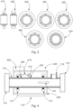
- Figure 3 sketches schematically example configurations of confining elements by longitudinal cross-sections 310 and 320 and transversal cross sections 330, 340, 350, 360 and 370, with fixation elements comprising various numbers and arrangements of discrete support pins, arranged e.g. in two rows 310 or three rows 320, equidistant arranged 330, 340, 360, 370 or irregular arranged 350, with a different number of support pins for mechanically coupling the frame of the confining element to the pipe of the pipe-fluid system.
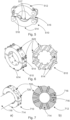
- Figure 7 sketches schematically a confining element 710 which is shown in the respective view a) and transversal cross-section b) including two rows of discrete support points 720 acting as fixation element, configured to couple the supporting frame 714 incorporating elastic members 716, as e.g. springs, to compensate for thermal expansion differences, i.e. keeping forces of the mechanical coupling between the supporting frame 714 and the pipe 116 constant.
- elastic members 716 as e.g. springs
Landscapes
- Physics & Mathematics (AREA)
- General Physics & Mathematics (AREA)
- Chemical & Material Sciences (AREA)
- Immunology (AREA)
- General Health & Medical Sciences (AREA)
- Pathology (AREA)
- Biochemistry (AREA)
- Analytical Chemistry (AREA)
- Health & Medical Sciences (AREA)
- Life Sciences & Earth Sciences (AREA)
- Engineering & Computer Science (AREA)
- Acoustics & Sound (AREA)
- General Engineering & Computer Science (AREA)
- Signal Processing (AREA)
- Mathematical Physics (AREA)
- Mechanical Engineering (AREA)
- Pure & Applied Mathematics (AREA)
- Mathematical Optimization (AREA)
- Mathematical Analysis (AREA)
- Algebra (AREA)
- Spectroscopy & Molecular Physics (AREA)
- Fluid Mechanics (AREA)
- Measuring Volume Flow (AREA)
- Measurement Of Mechanical Vibrations Or Ultrasonic Waves (AREA)
- Investigating Or Analyzing Materials By The Use Of Ultrasonic Waves (AREA)
Claims (13)
- Ein Messsystem (400) zur Bestimmung eines physikalischen Parameters eines Rohrfluidsystems (110), umfassend:ein Paar Begrenzungselemente (112, 114), die eingerichtet sind, Oberflächenschwingungsverformungen an jedem Ende des Rohrfluidsystems (110) zu reduzieren;ein Erregungssystem (412), das eingerichtet ist, ein mechanisches Schwingungsspektrum an einer Oberfläche des Rohrfluidsystems (110) zu erzeugen; undeine Schwingungsmessvorrichtung (430), die eingerichtet ist, mechanisch mit einer Außenfläche des Rohrfluidsystems (110) gekoppelt zu werden,wobei die Begrenzungselemente (112, 114) eingerichtet sind, Oberflächenschwingungsverformungen an einer Außenfläche eines Rohrfluidsystems (110) zu reduzieren,dadurch gekennzeichnet, dass jedes Begrenzungselement (112, 114) ferner umfasst:einen Tragrahmen (250), der eingerichtet ist, lösbar an einem Rohr (116) des Rohrfluidsystems (110) angebracht zu werden; undein Befestigungselement (232), das eingerichtet ist, lösbar montiert zu werden, um den Tragrahmen (250) mechanisch mit einer Außenfläche des Rohrs (116) zu koppeln,wobei das Begrenzungselement (112, 114) eingerichtet ist, einen definierten Knotenpunkt der Rohrschwingungen an der Position des Begrenzungselements zu erzeugen, wodurch radiale und Biegeschwingungsmoden lokal über den gesamten Umfang des Rohrs unterdrückt werden,wobei ein mechanisches Schwingungsspektrum der Schwingungsmoden des Rohrabschnitts zwischen den Begrenzungselementen zur Bestimmung des physikalischen Parameters verwendet werden kann.
- Das Messsystem (400) nach dem vorhergehenden Anspruch, umfassend einen Temperatursensor (440), der eingerichtet ist, eine Temperatur der Außenfläche des Rohrfluidsystems (110) zu bestimmen.
- Das Messsystem (400) nach einem der vorhergehenden Ansprüche, umfassend eine Bestimmungselektronik (420), die eingerichtet ist, den physikalischen Parameter des Rohrfluidsystems (110) basierend auf dem bereitgestellten mechanischen Schwingungsspektrum zu bestimmen,
wobei die Bestimmungselektronik (420) mittels elektrischer Signale mit dem Beschleunigungserfassungssystem (430) und/oder mit dem Temperatursensor (440) verbunden ist. - Das Messsystem (400) nach einem der vorhergehenden Ansprüche, umfassend eine Ein-/Ausgabeschnittstelle zur Eingabe charakteristischer Daten des Rohrs (116) des Rohrfluidsystems (110) und/oder von Prozessflüssigkeitsdaten des Rohrfluidsystems (110) und/oder zur Ausgabe des physikalischen Parameters des Rohrfluidsystems (110).
- Das Messsystem (400) nach einem der vorhergehenden Ansprüche, umfassend eine Trägerstruktur (410), die eingerichtet ist, das Erregungssystem (412) zu tragen und das Erregungssystem (412) zur Erzeugung der mechanischen Erregung zu befähigen; und/oder ein Schutzgehäuse (450), das das Paar von Begrenzungselementen (112, 114), das Beschleunigungserfassungssystem (430) und das Erregungssystem (412) umschließt.
- Das Messsystem (400) nach Anspruch 5, wobei der Tragrahmen (250) eingerichtet ist, lösbar an dem Rohr (116) mittels einer Anzahl von Rahmenelementen (512, 514) angebracht zu werden,wobei die Rahmenelemente (512, 514) eingerichtet sind, mechanisch verbunden zu werden, um den Tragrahmen (250) zu bilden;und wobei der Tragrahmen (250) eingerichtet ist, die Außenfläche des Rohrs (116) zu umfassen.
- Das Messsystem (400) nach einem der vorhergehenden Ansprüche, wobei das Befestigungselement (232) einen Kontaktring und/oder ein Paar von Kontaktringen und/oder ein Paar von Schneidkantenringen umfasst.
- Das Messsystem (400) nach einem der vorhergehenden Ansprüche, wobei eine axiale Dicke des Kontaktrings und/oder ein Abstand zwischen dem Paar von Kontaktringen und/oder ein Abstand zwischen dem Paar von Schneidkantenringen mindestens der Wandstärke des Rohrs (116) entspricht und vorzugsweise mindestens der zweifachen Wandstärke des Rohrs (116) des Rohrfluidsystems (110) entspricht.
- Das Messsystem (400) nach einem der vorhergehenden Ansprüche, wobei das Befestigungselement (232) eine Vielzahl von diskreten Stützstiften (620, 720, 820, 920) umfasst, die zwischen dem Tragrahmen (250) und der Außenfläche des Rohrs (116) angeordnet sind, um den Tragrahmen (250) mechanisch mit der Außenfläche des Rohrs (116) zu koppeln und die Oberflächenschwingungsverformungen (116) des Rohrfluidsystems (110) zu reduzieren.
- Das Messsystem (400) nach einem der vorhergehenden Ansprüche, wobei das Befestigungselement (232) mechanisch mit dem Tragrahmen (250) unter Verwendung thermischer Kompensationselemente gekoppelt ist, um die mechanische Kopplung in Bezug auf eine thermische Ausdehnung des Rohrs (116) zu kompensieren, und/oder wobei das Befestigungselement (232) mechanisch mit mindestens einer Abstimmmasse (930) gekoppelt ist.
- Das Messsystem (400) nach einem der vorhergehenden Ansprüche, wobei das Begrenzungselement (112, 114) einen Sensor zur Bestimmung der Stärke der mechanischen Kopplung zwischen dem Tragrahmen (250) und der Außenfläche des Rohrs (116) über das Befestigungselement (232) umfasst.
- Das Messsystem (400) nach einem der vorhergehenden Ansprüche, wobei das Begrenzungselement (112, 114) aktive Elemente zur Anpassung der Stärke der mechanischen Kopplung zwischen dem Tragrahmen (250) und der Außenfläche des Rohrs (116) umfasst.
- Bausatz, umfassend die Merkmale des Messsystems (400) nach einem der vorhergehenden Ansprüche.
Priority Applications (3)
| Application Number | Priority Date | Filing Date | Title |
|---|---|---|---|
| EP21154207.1A EP4036552B1 (de) | 2021-01-29 | 2021-01-29 | Messsystem zur bestimmung eines physikalischen parameters eines rohrfluidsystems |
| CN202210100192.8A CN114813933B (zh) | 2021-01-29 | 2022-01-27 | 用于确定管道流体系统的物理参数的测量系统 |
| US17/588,278 US12163973B2 (en) | 2021-01-29 | 2022-01-29 | Measurement system for determining a physical parameter of a pipe-fluid system |
Applications Claiming Priority (1)
| Application Number | Priority Date | Filing Date | Title |
|---|---|---|---|
| EP21154207.1A EP4036552B1 (de) | 2021-01-29 | 2021-01-29 | Messsystem zur bestimmung eines physikalischen parameters eines rohrfluidsystems |
Publications (3)
| Publication Number | Publication Date |
|---|---|
| EP4036552A1 EP4036552A1 (de) | 2022-08-03 |
| EP4036552C0 EP4036552C0 (de) | 2025-04-16 |
| EP4036552B1 true EP4036552B1 (de) | 2025-04-16 |
Family
ID=74418206
Family Applications (1)
| Application Number | Title | Priority Date | Filing Date |
|---|---|---|---|
| EP21154207.1A Active EP4036552B1 (de) | 2021-01-29 | 2021-01-29 | Messsystem zur bestimmung eines physikalischen parameters eines rohrfluidsystems |
Country Status (3)
| Country | Link |
|---|---|
| US (1) | US12163973B2 (de) |
| EP (1) | EP4036552B1 (de) |
| CN (1) | CN114813933B (de) |
Families Citing this family (2)
| Publication number | Priority date | Publication date | Assignee | Title |
|---|---|---|---|---|
| CN116658692B (zh) * | 2022-12-15 | 2025-10-10 | 河南九域恩湃电力技术有限公司 | 基于周期性结构的管道低频隔振准零刚度支架及实施方法 |
| EP4435406A1 (de) | 2023-03-22 | 2024-09-25 | Abb Schweiz Ag | Verfahren zur nichtinvasiven messung physikalischer parameter von flüssigkeiten in prozessrohren |
Family Cites Families (21)
| Publication number | Priority date | Publication date | Assignee | Title |
|---|---|---|---|---|
| US4181027A (en) * | 1978-04-19 | 1980-01-01 | Hughes Aircraft Company | Nodal/modal control and power intensification methods and apparatus for vibration testing |
| DE3128496A1 (de) * | 1981-07-18 | 1983-02-03 | Stetter Gmbh, 8940 Memmingen | Halterung fuer foerderrohre insbesondere bei betonpumpen |
| EP0088362A1 (de) | 1982-03-08 | 1983-09-14 | Fearon Development Corporation | Eindringungsfreie Druckmessung |
| AU2433592A (en) * | 1991-08-01 | 1993-03-02 | Micro Motion, Inc. | Coriolis effect mass flow meter |
| US6301973B1 (en) | 1999-04-30 | 2001-10-16 | The United States Of America As Represented By The Administrator Of The National Aeronautics And Space Administration | Non-intrusive pressure/multipurpose sensor and method |
| US7950609B2 (en) * | 2006-08-18 | 2011-05-31 | Kellogg Brown & Root Llc | Acoustic dampening pipe shoe |
| US8166801B2 (en) | 2007-09-30 | 2012-05-01 | Los Alamos National Security, Llc | Non-invasive fluid density and viscosity measurement |
| EP2462425A4 (de) | 2009-08-03 | 2017-04-05 | Ultimo Measurement, LLC | Verfahren und vorrichtung zur messung der physikalischen eigenschaften von freistrommaterialien in gefässen |
| CN105209901B (zh) | 2013-02-06 | 2018-08-24 | 乌尔蒂莫测量有限责任公司 | 用于测量容器中自由流动物质的物理性质的非侵入性方法 |
| US9816848B2 (en) | 2014-01-23 | 2017-11-14 | Ultimo Measurement Llc | Method and apparatus for non-invasively measuring physical properties of materials in a conduit |
| DE102014119073A1 (de) * | 2014-12-18 | 2016-06-23 | Endress+Hauser Flowtec Ag | Messaufnehmer vom Vibrationstyp |
| JP6582855B2 (ja) * | 2015-10-14 | 2019-10-02 | 東京電力ホールディングス株式会社 | 流量計測装置および流量計測方法 |
| ITUB20160606A1 (it) * | 2016-02-09 | 2017-08-09 | Saipem Spa | Ammortizzatore di vibrazioni per tubi |
| CN110114641B (zh) * | 2016-12-29 | 2021-08-03 | 恩德斯+豪斯流量技术股份有限公司 | 用于测量质量流率的电子振动测量系统 |
| DE102017012058A1 (de) * | 2017-12-28 | 2019-07-04 | Endress+Hauser Flowtec Ag | Messgerät vom Vibraationstyp mit einem Messrohr |
| EP3598256B1 (de) * | 2018-07-16 | 2023-11-29 | ABB Schweiz AG | Vorrichtung zur vorhersage der verbleibenden lebensdauer eines elektrischen systems |
| CN108644478A (zh) * | 2018-07-17 | 2018-10-12 | 浙江海洋大学 | 一种管道减振装置 |
| CN110745209A (zh) * | 2019-11-29 | 2020-02-04 | 烟台大学 | 一种管路与减振组件的连接结构、连接方法及控制系统 |
| CN211899681U (zh) * | 2019-12-11 | 2020-11-10 | 上海融测空间测绘有限公司 | 一种建筑施工混凝土泵管固定结构 |
| CN211821049U (zh) * | 2020-03-06 | 2020-10-30 | 陕西骁龙建设工程有限公司 | 一种管道工程用管路支撑件 |
| CN111396680A (zh) * | 2020-03-19 | 2020-07-10 | 上海核工程研究设计院有限公司 | 一种核电站的隔振支架 |
-
2021
- 2021-01-29 EP EP21154207.1A patent/EP4036552B1/de active Active
-
2022
- 2022-01-27 CN CN202210100192.8A patent/CN114813933B/zh active Active
- 2022-01-29 US US17/588,278 patent/US12163973B2/en active Active
Also Published As
| Publication number | Publication date |
|---|---|
| CN114813933B (zh) | 2025-12-12 |
| CN114813933A (zh) | 2022-07-29 |
| US12163973B2 (en) | 2024-12-10 |
| EP4036552C0 (de) | 2025-04-16 |
| US20220252494A1 (en) | 2022-08-11 |
| EP4036552A1 (de) | 2022-08-03 |
Similar Documents
| Publication | Publication Date | Title |
|---|---|---|
| CN104813147B (zh) | 对振动计中流体管的截面面积的改变的改进检测 | |
| CN105899917B (zh) | 密度测量设备 | |
| US20230341247A1 (en) | Vibronic measuring system | |
| US8966994B2 (en) | Method for monitoring a body inserted in a conduit and insert for electromagnetic resonance measurements | |
| US12163973B2 (en) | Measurement system for determining a physical parameter of a pipe-fluid system | |
| GB2350426A (en) | Vibrating tube meter | |
| JP2008514916A5 (de) | ||
| JP2008514916A (ja) | コリオリ流量計における左右の固有ベクトルの流入量決定 | |
| KR20060088116A (ko) | 코리올리 유량계용 진단 장치 및 방법 | |
| US7774150B2 (en) | Meter electronics and methods for determining one or more of a stiffness coefficient or a mass coefficient | |
| CN116368367A (zh) | 电子振动测量系统 | |
| EP3164679B1 (de) | Verfahren und vorrichtung zur ermittlung eines strömungsimpulses | |
| US7523005B2 (en) | Clamp-on coriolis mass flow meter using in-situ calibration | |
| EP3837510B1 (de) | Verfahren zur bestimmung, wann ein steifigkeitskoeffizient eines durchflussmessers zu prüfen ist | |
| RU2592041C2 (ru) | Способ и устройство для оценки виброустойчивости компонента клапана управления текучей средой | |
| US20260049854A1 (en) | Mode excitation detection for a vibratory flowmeter and related methods | |
| US20220244158A1 (en) | Method for Determining a Physical Parameter of a Pipe-Fluid System | |
| JP5836427B2 (ja) | コリオリ流量計における左右の固有ベクトルの流入量決定 | |
| HK1213043B (en) | Improved detection of a change in the cross-sectional area of a fluid tube in a vibrating meter | |
| HK1216925A1 (zh) | 用於振动仪的方法和装置 | |
| HK1216925B (en) | Method and apparatus for a vibratory meter |
Legal Events
| Date | Code | Title | Description |
|---|---|---|---|
| PUAI | Public reference made under article 153(3) epc to a published international application that has entered the european phase |
Free format text: ORIGINAL CODE: 0009012 |
|
| STAA | Information on the status of an ep patent application or granted ep patent |
Free format text: STATUS: THE APPLICATION HAS BEEN PUBLISHED |
|
| AK | Designated contracting states |
Kind code of ref document: A1 Designated state(s): AL AT BE BG CH CY CZ DE DK EE ES FI FR GB GR HR HU IE IS IT LI LT LU LV MC MK MT NL NO PL PT RO RS SE SI SK SM TR |
|
| STAA | Information on the status of an ep patent application or granted ep patent |
Free format text: STATUS: REQUEST FOR EXAMINATION WAS MADE |
|
| 17P | Request for examination filed |
Effective date: 20230203 |
|
| RBV | Designated contracting states (corrected) |
Designated state(s): AL AT BE BG CH CY CZ DE DK EE ES FI FR GB GR HR HU IE IS IT LI LT LU LV MC MK MT NL NO PL PT RO RS SE SI SK SM TR |
|
| GRAP | Despatch of communication of intention to grant a patent |
Free format text: ORIGINAL CODE: EPIDOSNIGR1 |
|
| STAA | Information on the status of an ep patent application or granted ep patent |
Free format text: STATUS: GRANT OF PATENT IS INTENDED |
|
| INTG | Intention to grant announced |
Effective date: 20241121 |
|
| GRAS | Grant fee paid |
Free format text: ORIGINAL CODE: EPIDOSNIGR3 |
|
| GRAA | (expected) grant |
Free format text: ORIGINAL CODE: 0009210 |
|
| STAA | Information on the status of an ep patent application or granted ep patent |
Free format text: STATUS: THE PATENT HAS BEEN GRANTED |
|
| AK | Designated contracting states |
Kind code of ref document: B1 Designated state(s): AL AT BE BG CH CY CZ DE DK EE ES FI FR GB GR HR HU IE IS IT LI LT LU LV MC MK MT NL NO PL PT RO RS SE SI SK SM TR |
|
| REG | Reference to a national code |
Ref country code: GB Ref legal event code: FG4D |
|
| REG | Reference to a national code |
Ref country code: CH Ref legal event code: EP Ref country code: DE Ref legal event code: R096 Ref document number: 602021029095 Country of ref document: DE |
|
| REG | Reference to a national code |
Ref country code: IE Ref legal event code: FG4D |
|
| U01 | Request for unitary effect filed |
Effective date: 20250514 |
|
| U07 | Unitary effect registered |
Designated state(s): AT BE BG DE DK EE FI FR IT LT LU LV MT NL PT RO SE SI Effective date: 20250520 |
|
| PG25 | Lapsed in a contracting state [announced via postgrant information from national office to epo] |
Ref country code: ES Free format text: LAPSE BECAUSE OF FAILURE TO SUBMIT A TRANSLATION OF THE DESCRIPTION OR TO PAY THE FEE WITHIN THE PRESCRIBED TIME-LIMIT Effective date: 20250416 |
|
| PG25 | Lapsed in a contracting state [announced via postgrant information from national office to epo] |
Ref country code: GR Free format text: LAPSE BECAUSE OF FAILURE TO SUBMIT A TRANSLATION OF THE DESCRIPTION OR TO PAY THE FEE WITHIN THE PRESCRIBED TIME-LIMIT Effective date: 20250717 |
|
| PG25 | Lapsed in a contracting state [announced via postgrant information from national office to epo] |
Ref country code: PL Free format text: LAPSE BECAUSE OF FAILURE TO SUBMIT A TRANSLATION OF THE DESCRIPTION OR TO PAY THE FEE WITHIN THE PRESCRIBED TIME-LIMIT Effective date: 20250416 |
|
| PG25 | Lapsed in a contracting state [announced via postgrant information from national office to epo] |
Ref country code: HR Free format text: LAPSE BECAUSE OF FAILURE TO SUBMIT A TRANSLATION OF THE DESCRIPTION OR TO PAY THE FEE WITHIN THE PRESCRIBED TIME-LIMIT Effective date: 20250416 |
|
| PG25 | Lapsed in a contracting state [announced via postgrant information from national office to epo] |
Ref country code: RS Free format text: LAPSE BECAUSE OF FAILURE TO SUBMIT A TRANSLATION OF THE DESCRIPTION OR TO PAY THE FEE WITHIN THE PRESCRIBED TIME-LIMIT Effective date: 20250716 |
|
| PG25 | Lapsed in a contracting state [announced via postgrant information from national office to epo] |
Ref country code: IS Free format text: LAPSE BECAUSE OF FAILURE TO SUBMIT A TRANSLATION OF THE DESCRIPTION OR TO PAY THE FEE WITHIN THE PRESCRIBED TIME-LIMIT Effective date: 20250816 |
|
| PG25 | Lapsed in a contracting state [announced via postgrant information from national office to epo] |
Ref country code: SM Free format text: LAPSE BECAUSE OF FAILURE TO SUBMIT A TRANSLATION OF THE DESCRIPTION OR TO PAY THE FEE WITHIN THE PRESCRIBED TIME-LIMIT Effective date: 20250416 |
|
| PG25 | Lapsed in a contracting state [announced via postgrant information from national office to epo] |
Ref country code: CZ Free format text: LAPSE BECAUSE OF FAILURE TO SUBMIT A TRANSLATION OF THE DESCRIPTION OR TO PAY THE FEE WITHIN THE PRESCRIBED TIME-LIMIT Effective date: 20250416 |
|
| PG25 | Lapsed in a contracting state [announced via postgrant information from national office to epo] |
Ref country code: SK Free format text: LAPSE BECAUSE OF FAILURE TO SUBMIT A TRANSLATION OF THE DESCRIPTION OR TO PAY THE FEE WITHIN THE PRESCRIBED TIME-LIMIT Effective date: 20250416 |
|
| PLBE | No opposition filed within time limit |
Free format text: ORIGINAL CODE: 0009261 |
|
| STAA | Information on the status of an ep patent application or granted ep patent |
Free format text: STATUS: NO OPPOSITION FILED WITHIN TIME LIMIT |
|
| REG | Reference to a national code |
Ref country code: CH Ref legal event code: L10 Free format text: ST27 STATUS EVENT CODE: U-0-0-L10-L00 (AS PROVIDED BY THE NATIONAL OFFICE) Effective date: 20260225 |
|
| U20 | Renewal fee for the european patent with unitary effect paid |
Year of fee payment: 6 Effective date: 20260129 |
|
| 26N | No opposition filed |
Effective date: 20260119 |
|
| PGFP | Annual fee paid to national office [announced via postgrant information from national office to epo] |
Ref country code: GB Payment date: 20260123 Year of fee payment: 6 |
|
| PGFP | Annual fee paid to national office [announced via postgrant information from national office to epo] |
Ref country code: NO Payment date: 20260123 Year of fee payment: 6 |