EP4036477A2 - Vehicle oven having an improved heating element - Google Patents
Vehicle oven having an improved heating element Download PDFInfo
- Publication number
- EP4036477A2 EP4036477A2 EP22154039.6A EP22154039A EP4036477A2 EP 4036477 A2 EP4036477 A2 EP 4036477A2 EP 22154039 A EP22154039 A EP 22154039A EP 4036477 A2 EP4036477 A2 EP 4036477A2
- Authority
- EP
- European Patent Office
- Prior art keywords
- heating element
- assembly
- metallic layer
- layer
- metallic
- Prior art date
- Legal status (The legal status is an assumption and is not a legal conclusion. Google has not performed a legal analysis and makes no representation as to the accuracy of the status listed.)
- Pending
Links
Images



Classifications
-
- F—MECHANICAL ENGINEERING; LIGHTING; HEATING; WEAPONS; BLASTING
- F24—HEATING; RANGES; VENTILATING
- F24C—DOMESTIC STOVES OR RANGES ; DETAILS OF DOMESTIC STOVES OR RANGES, OF GENERAL APPLICATION
- F24C7/00—Stoves or ranges heated by electric energy
- F24C7/06—Arrangement or mounting of electric heating elements
-
- F—MECHANICAL ENGINEERING; LIGHTING; HEATING; WEAPONS; BLASTING
- F24—HEATING; RANGES; VENTILATING
- F24C—DOMESTIC STOVES OR RANGES ; DETAILS OF DOMESTIC STOVES OR RANGES, OF GENERAL APPLICATION
- F24C15/00—Details
- F24C15/30—Arrangements for mounting stoves or ranges in particular locations
-
- F—MECHANICAL ENGINEERING; LIGHTING; HEATING; WEAPONS; BLASTING
- F24—HEATING; RANGES; VENTILATING
- F24C—DOMESTIC STOVES OR RANGES ; DETAILS OF DOMESTIC STOVES OR RANGES, OF GENERAL APPLICATION
- F24C15/00—Details
- F24C15/32—Arrangements of ducts for hot gases, e.g. in or around baking ovens
- F24C15/322—Arrangements of ducts for hot gases, e.g. in or around baking ovens with forced circulation
- F24C15/325—Arrangements of ducts for hot gases, e.g. in or around baking ovens with forced circulation electrically-heated
-
- F—MECHANICAL ENGINEERING; LIGHTING; HEATING; WEAPONS; BLASTING
- F24—HEATING; RANGES; VENTILATING
- F24C—DOMESTIC STOVES OR RANGES ; DETAILS OF DOMESTIC STOVES OR RANGES, OF GENERAL APPLICATION
- F24C7/00—Stoves or ranges heated by electric energy
- F24C7/06—Arrangement or mounting of electric heating elements
- F24C7/067—Arrangement or mounting of electric heating elements on ranges
Definitions
- Embodiments relate to an oven for heating food. More specifically, embodiments relate to a vehicle oven having an improved heating element.
- ovens for use in vehicles typically use a heating element consisting of a plurality of tubes, each tube connected between two power phases and with a resistive element inside.
- the tubes have large diameters, lengths, and radii, making complex shapes difficult to create.
- the production process involves a lot of manual labor, making the elements relatively expensive, and the tubes need to be placed next to each other in the airflow, so the assembly has a relatively large thickness.
- the current designs have drawbacks such as air turbulence and thus contributing to the noise of the oven.
- the tubes typically result in a large cold area, also referred to as a run out, which affects even throughout the oven.
- An oven heating element assembly including a heating element operable to heat air that flows across the heating element, wherein the heating element includes a disk having a metallic layer, a ceramic layer sandwiched between the metallic layer and a second metallic layer, and a fan operable to cause air to flow across the heating element.
- the fan can be configured to pull air from an oven cavity and push it over the heating element.
- the ceramic layer can include at least three distinct individual sections. Each of the at least three distinct individual sections can be disconnected from each other. At least three distinct individual sections can cover each of the 360 degrees of the disk. The at least three distinct individual sections can partially overlap each other. At least one of the metallic layers can include a plurality of fin, pins, ribs, or projections radiating therefrom. The fin can radiates in a direction orthogonal to a plane defined by a primary surface of the at least one of the metallic layers.
- the assembly can include at least one attachment point for attaching the disk to an inner portion of the oven.
- the attachment point can include at least one aerodynamic feature, to reduce the impact on the airflow.
- the aerodynamic feature can includes at least one rounded edge. The rounded edge can face gravitationally down.
- the attachments points can also be used to supply the power through.
- FIG. 1 a partial view of an exemplary embodiment of an oven heating element in accordance with the disclosure is shown in FIG. 1 and is designated generally by reference character 100.
- FIGS. 2-5 Other embodiments of the heating element and portions thereof in accordance with the disclosure, or aspects thereof, are provided in FIGS. 2-5, as will be described.
- the heating element described herein described herein assures that the ceramic elements are encapsulated and protected, it is much more compact than previous designs and also allows for improving the airflow, reducing noise and increasing air contact surface.
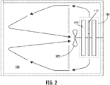
- FIG. 1 is a perspective view of an inner portion of the oven 100 showing the fan 102 and heating element 104. As show in in Fig. 2, the fan 102 pulls air from an oven cavity and pushes it over the heating element 104. The hot air is then pushed out back into the oven cavity and heats whatever is placed in the oven.
- FIG. 3 is a perspective view of the heating element 104.
- the heating element 104 includes in the shape of a disk, having an empty center, having an outer metallic layer 108 and a ceramic layer 110 (shown in Fig. 4) sandwiched within the metallic layer 108.
- the outer metallic layer 108 can include a fin or plurality of fins 110 radiating therefrom in order to increase the heat sink ability of the heating element and to direct the airflow in a particular direction in order to avoid cold spots within the oven.
- the fins 110 can radiate orthogonal to a plane defined by the metallic layer 108.
- the heating element 104 can be attached to the inner portion of the oven using a one or plurality of attachment points 112 for attaching the disk to an inner portion of the oven 100.
- the attachment points 112 can house a conductor to supply the electricity and heat to the heating element 104 or to simply keep the heating element 104 in place. Details is of the attachment points are shown in Fig. 5
- FIG. 4a-4c are front sectional views of the heating element 104 showing the various possible arrangements of the ceramic sections 110 within the metallic layer 108.
- Each of the ceramic sections shown here include at least three distinct individual sections (a, b, c). Each of the section (a, b, c) are disconnected from each other.
- the individual sections (a, b, c) cover every radial direction across 360 degrees emanating from the center of the heating element 104.
- the three distinct individual sections (a, b, c) partially overlap with each other allowing the emanating heat to be evenly dispersed and compensate for cold zones or avoid hot spots.
- a plurality of segments (a, b, c) is a multiple of three.
- FIG. 5a-5c are front views of the attachment points of Fig. 1.
- the attachment points 112 include at least one aerodynamic feature 113 which helps reduce noise and streamline the airflow within the oven.
- the aerodynamic features 113 can include rounded edges, teardrops, cylindrical, oval, elliptical shapes.
- the attachments points can also be used to supply the power.
Landscapes
- Engineering & Computer Science (AREA)
- Chemical & Material Sciences (AREA)
- Combustion & Propulsion (AREA)
- Mechanical Engineering (AREA)
- General Engineering & Computer Science (AREA)
- Resistance Heating (AREA)
- Electric Stoves And Ranges (AREA)
Abstract
Description
- Embodiments relate to an oven for heating food. More specifically, embodiments relate to a vehicle oven having an improved heating element.
- Conventional ovens for use in vehicles, such as aircraft, typically use a heating element consisting of a plurality of tubes, each tube connected between two power phases and with a resistive element inside. The tubes have large diameters, lengths, and radii, making complex shapes difficult to create. The production process involves a lot of manual labor, making the elements relatively expensive, and the tubes need to be placed next to each other in the airflow, so the assembly has a relatively large thickness. The current designs have drawbacks such as air turbulence and thus contributing to the noise of the oven. The tubes typically result in a large cold area, also referred to as a run out, which affects even throughout the oven. Although such ovens and components have generally been considered satisfactory for their intended purpose, there is still a need in the art for improved ovens and heating elements. The present disclosure provides a solution for this need.
- An oven heating element assembly including a heating element operable to heat air that flows across the heating element, wherein the heating element includes a disk having a metallic layer, a ceramic layer sandwiched between the metallic layer and a second metallic layer, and a fan operable to cause air to flow across the heating element. The fan can be configured to pull air from an oven cavity and push it over the heating element.
- The ceramic layer can include at least three distinct individual sections. Each of the at least three distinct individual sections can be disconnected from each other. At least three distinct individual sections can cover each of the 360 degrees of the disk. The at least three distinct individual sections can partially overlap each other. At least one of the metallic layers can include a plurality of fin, pins, ribs, or projections radiating therefrom. The fin can radiates in a direction orthogonal to a plane defined by a primary surface of the at least one of the metallic layers.
- The assembly can include at least one attachment point for attaching the disk to an inner portion of the oven. The attachment point can include at least one aerodynamic feature, to reduce the impact on the airflow. The aerodynamic feature can includes at least one rounded edge. The rounded edge can face gravitationally down. The attachments points can also be used to supply the power through.
- These and other features of the systems and methods of the subject disclosure will become more readily apparent to those skilled in the art from the following detailed description of the preferred embodiments taken in conjunction with the drawings.
- So that those skilled in the art to which the subject disclosure appertains will readily understand how to make and use the devices and methods of the subject disclosure without undue experimentation, embodiments thereof will be described in detail herein below with reference to certain figures, wherein:
- FIG. 1 is a perspective view of an inner portion of the oven showing the fan and heating element;
- FIG. 2 is a diagram showing the airflow within the oven of FIG. 1;
- FIG. 3 is a perspective view of the heating element showing a fin arrangement;
- FIG. 4a-4c are front sectional views of the heating element showing the various possible arrangements of the ceramic sections; and
- FIG. 5 are front views of the attachment points of Fig. 1
- Reference will now be made to the drawings wherein like reference numerals identify similar structural features or aspects of the subject disclosure. For purposes of explanation and illustration, and not limitation, a partial view of an exemplary embodiment of an oven heating element in accordance with the disclosure is shown in FIG. 1 and is designated generally by
reference character 100. Other embodiments of the heating element and portions thereof in accordance with the disclosure, or aspects thereof, are provided in FIGS. 2-5, as will be described. The heating element described herein described herein assures that the ceramic elements are encapsulated and protected, it is much more compact than previous designs and also allows for improving the airflow, reducing noise and increasing air contact surface. - FIG. 1 is a perspective view of an inner portion of the
oven 100 showing thefan 102 andheating element 104. As show in in Fig. 2, thefan 102 pulls air from an oven cavity and pushes it over theheating element 104. The hot air is then pushed out back into the oven cavity and heats whatever is placed in the oven. - FIG. 3 is a perspective view of the
heating element 104. Theheating element 104 includes in the shape of a disk, having an empty center, having an outermetallic layer 108 and a ceramic layer 110 (shown in Fig. 4) sandwiched within themetallic layer 108. The outermetallic layer 108 can include a fin or plurality offins 110 radiating therefrom in order to increase the heat sink ability of the heating element and to direct the airflow in a particular direction in order to avoid cold spots within the oven. Thefins 110 can radiate orthogonal to a plane defined by themetallic layer 108. Theheating element 104 can be attached to the inner portion of the oven using a one or plurality of attachment points 112 for attaching the disk to an inner portion of theoven 100. The attachment points 112 can house a conductor to supply the electricity and heat to theheating element 104 or to simply keep theheating element 104 in place. Details is of the attachment points are shown in Fig. 5 - FIG. 4a-4c are front sectional views of the
heating element 104 showing the various possible arrangements of theceramic sections 110 within themetallic layer 108. Each of the ceramic sections shown here include at least three distinct individual sections (a, b, c). Each of the section (a, b, c) are disconnected from each other. In Fig. 4b, the individual sections (a, b, c) cover every radial direction across 360 degrees emanating from the center of theheating element 104. The three distinct individual sections (a, b, c) partially overlap with each other allowing the emanating heat to be evenly dispersed and compensate for cold zones or avoid hot spots. Also in order to keep a balanced load, it is preferred that a plurality of segments (a, b, c) is a multiple of three. - FIG. 5a-5c are front views of the attachment points of Fig. 1. The attachment points 112 include at least one
aerodynamic feature 113 which helps reduce noise and streamline the airflow within the oven. Theaerodynamic features 113 can include rounded edges, teardrops, cylindrical, oval, elliptical shapes. The attachments points can also be used to supply the power. - The methods and systems of the present disclosure, as described above and shown in the drawings, provide for heating elements with superior properties including Optimized airflow, Decreased thickness, compensation for cold zones, lower recurring production costs, and simpler installation procedures. While the apparatus and methods of the subject disclosure have been shown and described with reference to preferred embodiments, those skilled in the art will readily appreciate that changes and/or modifications may be made thereto without departing from the scope of the subject disclosure.
Claims (15)
- An oven heating element assembly comprising:
a heating element operable to heat air that flows across the heating element, wherein the heating element includes:a disk having a first metallic layer (108), a ceramic layer (110) sandwiched between the first metallic layer (108) and a second metallic layer (108); anda fan operable to cause air to flow across the heating element. - The assembly of claim 1, wherein the ceramic layer (110) includes at least three distinct individual sections.
- The assembly of claim 2, wherein each of the at least three distinct individual sections are disconnected from each other.
- The assembly of claim 2, wherein the at least three distinct individual sections cover each of the 360 degrees of the disk.
- The assembly of any preceding claim, wherein the at least three distinct individual sections partially overlap.
- The assembly of any preceding claim, wherein at least one of the metallic layers (108) includes a fin radiating therefrom.
- The assembly of claim 6, wherein the fin radiates in a direction orthogonal to a plane defined by a primary surface of the at least one of the metallic layers (108).
- The assembly of any preceding claim, further comprising at least one attachment point for attaching the disk to an inner portion of the oven.
- The assembly of claim 8, wherein the attachment point includes at least one aerodynamic feature, to reduce the impact on the airflow.
- The assembly of any preceding claim, wherein the fan is configured to pull air from an oven cavity and push it over the heating element.
- A heating element operable to heat air that flows across the heating element comprising:a first metallic layer (108) defined by a closed circular shape forming a front face of the heating element;a second metallic layer (108) forming a back face of the heating element; anda ceramic layer (110) disposed between the first metallic layer (108) and the second metallic layer (108).
- The heating element of claim 13, wherein ceramic layer (110) is thinner than either of the metallic layers (108).
- The heating element of claim 13, wherein the ceramic layer (110) is fully enclosed by the first metallic layer (108) and the second metallic layer (108).
- The heating element of claim 13, wherein the ceramic layer (110) is flush against the first metallic layer (108).
- The heating element of claim 13, wherein the ceramic layer (110) is flush against the second metallic layer (108).
Applications Claiming Priority (1)
| Application Number | Priority Date | Filing Date | Title |
|---|---|---|---|
| US17/163,103 US12117183B2 (en) | 2021-01-29 | 2021-01-29 | Vehicle oven having an improved heating element |
Publications (2)
| Publication Number | Publication Date |
|---|---|
| EP4036477A2 true EP4036477A2 (en) | 2022-08-03 |
| EP4036477A3 EP4036477A3 (en) | 2022-10-26 |
Family
ID=80122536
Family Applications (1)
| Application Number | Title | Priority Date | Filing Date |
|---|---|---|---|
| EP22154039.6A Pending EP4036477A3 (en) | 2021-01-29 | 2022-01-28 | Vehicle oven having an improved heating element |
Country Status (2)
| Country | Link |
|---|---|
| US (1) | US12117183B2 (en) |
| EP (1) | EP4036477A3 (en) |
Citations (1)
| Publication number | Priority date | Publication date | Assignee | Title |
|---|---|---|---|---|
| EP1288580A1 (en) * | 2001-08-29 | 2003-03-05 | Whirlpool Corporation | Cooking oven |
Family Cites Families (18)
| Publication number | Priority date | Publication date | Assignee | Title |
|---|---|---|---|---|
| US1050105A (en) | 1911-07-28 | 1913-01-14 | Copeman Electric Stove Company | Electrically-heated oven construction. |
| US4430541A (en) * | 1981-01-14 | 1984-02-07 | Raytheon Company | Combination microwave gas convection oven |
| US5204503A (en) * | 1991-12-17 | 1993-04-20 | Raytheon Company | Microwave oven having convection and griddle features |
| CA2180618A1 (en) * | 1995-07-17 | 1997-01-18 | Dennis J. Vaseloff | Food warmer foil heater and sensor assembly including plural zone heater assembly |
| FR2796199B1 (en) | 1999-07-09 | 2001-10-12 | Muller Et Cie | METHOD FOR MANUFACTURING A HEATING ELEMENT FOR A HEATING OR COOKING APPARATUS, A HEATING ELEMENT THUS OBTAINED AND APPARATUS THUS EQUIPPED |
| FR2831244B1 (en) | 2001-10-23 | 2004-03-12 | S O P A R A | HEATING DEVICE WITH INFRARED RADIATION |
| WO2004089039A1 (en) * | 2003-03-31 | 2004-10-14 | Ibiden Co., Ltd. | Heater for semiconductor manufacturing and inspecting equipment |
| DE102004033372A1 (en) | 2004-07-09 | 2006-02-16 | BSH Bosch und Siemens Hausgeräte GmbH | A method for constructing a heating element for a domestic recirculating fan oven has flat annular formers and circular metallic heater tracks stacked in a laminated form |
| CN101203714A (en) * | 2005-04-22 | 2008-06-18 | 范松皇家油墨厂 | Oven with uniform hot air flow in the preparation area |
| US20100193507A1 (en) | 2009-01-30 | 2010-08-05 | General Electric Company | Speedcooking oven |
| JP5821389B2 (en) * | 2011-04-20 | 2015-11-24 | 三菱マテリアル株式会社 | Power module substrate manufacturing method and power module substrate |
| US20130156906A1 (en) | 2011-12-14 | 2013-06-20 | J.K. Raghavan | Salamander Element for Closed System Oven |
| CN109156050A (en) * | 2016-04-07 | 2019-01-04 | 美题隆公司 | Beryllium oxide integral resistance heater |
| JP6195029B1 (en) | 2016-07-20 | 2017-09-13 | Toto株式会社 | Electrostatic chuck |
| WO2018179891A1 (en) * | 2017-03-28 | 2018-10-04 | 住友電気工業株式会社 | Wafer holding body |
| JP6615966B1 (en) * | 2018-06-29 | 2019-12-04 | 株式会社日本輸出自動車検査センター | Automotive high temperature pest control equipment |
| KR102177948B1 (en) * | 2018-10-16 | 2020-11-12 | 엘지전자 주식회사 | Electric Heater |
| US11564396B2 (en) * | 2019-03-11 | 2023-01-31 | B/E Aerospace, Inc. | Oven with improved airflow |
-
2021
- 2021-01-29 US US17/163,103 patent/US12117183B2/en active Active
-
2022
- 2022-01-28 EP EP22154039.6A patent/EP4036477A3/en active Pending
Patent Citations (1)
| Publication number | Priority date | Publication date | Assignee | Title |
|---|---|---|---|---|
| EP1288580A1 (en) * | 2001-08-29 | 2003-03-05 | Whirlpool Corporation | Cooking oven |
Also Published As
| Publication number | Publication date |
|---|---|
| US20220243921A1 (en) | 2022-08-04 |
| US12117183B2 (en) | 2024-10-15 |
| EP4036477A3 (en) | 2022-10-26 |
Similar Documents
| Publication | Publication Date | Title |
|---|---|---|
| CN110274266B (en) | Improved commercial microwave oven | |
| EP2313946B3 (en) | Radome comprising an internal cooling system | |
| CN104619994A (en) | Wall ring for a fan with heating element | |
| CN107684342A (en) | Electric pressure cooking saucepan | |
| CN203953351U (en) | The radiator structure of electric-heating cooking utensil | |
| US10278239B2 (en) | Cooling assembly for an induction hob | |
| US12117183B2 (en) | Vehicle oven having an improved heating element | |
| CN215112777U (en) | Bottom plate subassembly and cooking device | |
| CN108040453B (en) | Radiating fin, radiator with radiating fin and electric box with radiator | |
| CN110972454B (en) | Frequency converter heat radiation structure and heating furnace | |
| CN108317596B (en) | A control box for heater and heater | |
| US6592075B2 (en) | Aircraft supplemental air heater | |
| US4412117A (en) | Microwave oven feed system | |
| CN112842092B (en) | Oven with a baking oven | |
| CN221227762U (en) | Electromagnetic heating device and cooking utensil | |
| CN219645557U (en) | Heating tube assembly and cooking apparatus | |
| CN208029132U (en) | Coil panel and cooking apparatus | |
| CN108113497B (en) | Coil panel seat, coil panel and electromagnetic cooking utensil | |
| CN222424045U (en) | Mounting bracket, coil pan assembly and cooking appliance | |
| CN207936792U (en) | Radiator and cooking apparatus with it | |
| CN222703361U (en) | Wire reel bracket, wire reel assembly and electromagnetic cooking utensil | |
| CN223512177U (en) | Heating device and bathroom heater | |
| CN215187466U (en) | Eddy current induction coil | |
| CN216897746U (en) | Guide ring assembly and air conditioner | |
| CN212029633U (en) | Heat radiation structure of electric heating furnace |
Legal Events
| Date | Code | Title | Description |
|---|---|---|---|
| PUAI | Public reference made under article 153(3) epc to a published international application that has entered the european phase |
Free format text: ORIGINAL CODE: 0009012 |
|
| STAA | Information on the status of an ep patent application or granted ep patent |
Free format text: STATUS: THE APPLICATION HAS BEEN PUBLISHED |
|
| AK | Designated contracting states |
Kind code of ref document: A2 Designated state(s): AL AT BE BG CH CY CZ DE DK EE ES FI FR GB GR HR HU IE IS IT LI LT LU LV MC MK MT NL NO PL PT RO RS SE SI SK SM TR |
|
| PUAL | Search report despatched |
Free format text: ORIGINAL CODE: 0009013 |
|
| AK | Designated contracting states |
Kind code of ref document: A3 Designated state(s): AL AT BE BG CH CY CZ DE DK EE ES FI FR GB GR HR HU IE IS IT LI LT LU LV MC MK MT NL NO PL PT RO RS SE SI SK SM TR |
|
| RIC1 | Information provided on ipc code assigned before grant |
Ipc: H05B 3/28 20060101ALI20220920BHEP Ipc: F24C 15/32 20060101ALI20220920BHEP Ipc: F24C 7/06 20060101AFI20220920BHEP |
|
| STAA | Information on the status of an ep patent application or granted ep patent |
Free format text: STATUS: REQUEST FOR EXAMINATION WAS MADE |
|
| 17P | Request for examination filed |
Effective date: 20230426 |
|
| RBV | Designated contracting states (corrected) |
Designated state(s): AL AT BE BG CH CY CZ DE DK EE ES FI FR GB GR HR HU IE IS IT LI LT LU LV MC MK MT NL NO PL PT RO RS SE SI SK SM TR |
|
| STAA | Information on the status of an ep patent application or granted ep patent |
Free format text: STATUS: EXAMINATION IS IN PROGRESS |
|
| 17Q | First examination report despatched |
Effective date: 20250721 |
|
| RAP1 | Party data changed (applicant data changed or rights of an application transferred) |
Owner name: B/E AEROSPACE INC. |