EP4036443A1 - Electronic expansion valve - Google Patents
Electronic expansion valve Download PDFInfo
- Publication number
- EP4036443A1 EP4036443A1 EP20868592.5A EP20868592A EP4036443A1 EP 4036443 A1 EP4036443 A1 EP 4036443A1 EP 20868592 A EP20868592 A EP 20868592A EP 4036443 A1 EP4036443 A1 EP 4036443A1
- Authority
- EP
- European Patent Office
- Prior art keywords
- segment
- disposed
- guide sleeve
- housing
- pipe
- Prior art date
- Legal status (The legal status is an assumption and is not a legal conclusion. Google has not performed a legal analysis and makes no representation as to the accuracy of the status listed.)
- Pending
Links
Images




Classifications
-
- F—MECHANICAL ENGINEERING; LIGHTING; HEATING; WEAPONS; BLASTING
- F25—REFRIGERATION OR COOLING; COMBINED HEATING AND REFRIGERATION SYSTEMS; HEAT PUMP SYSTEMS; MANUFACTURE OR STORAGE OF ICE; LIQUEFACTION SOLIDIFICATION OF GASES
- F25B—REFRIGERATION MACHINES, PLANTS OR SYSTEMS; COMBINED HEATING AND REFRIGERATION SYSTEMS; HEAT PUMP SYSTEMS
- F25B41/00—Fluid-circulation arrangements
- F25B41/30—Expansion means; Dispositions thereof
- F25B41/31—Expansion valves
- F25B41/34—Expansion valves with the valve member being actuated by electric means, e.g. by piezoelectric actuators
- F25B41/35—Expansion valves with the valve member being actuated by electric means, e.g. by piezoelectric actuators by rotary motors, e.g. by stepping motors
-
- F—MECHANICAL ENGINEERING; LIGHTING; HEATING; WEAPONS; BLASTING
- F16—ENGINEERING ELEMENTS AND UNITS; GENERAL MEASURES FOR PRODUCING AND MAINTAINING EFFECTIVE FUNCTIONING OF MACHINES OR INSTALLATIONS; THERMAL INSULATION IN GENERAL
- F16K—VALVES; TAPS; COCKS; ACTUATING-FLOATS; DEVICES FOR VENTING OR AERATING
- F16K1/00—Lift valves or globe valves, i.e. cut-off apparatus with closure members having at least a component of their opening and closing motion perpendicular to the closing faces
- F16K1/02—Lift valves or globe valves, i.e. cut-off apparatus with closure members having at least a component of their opening and closing motion perpendicular to the closing faces with screw-spindle
-
- F—MECHANICAL ENGINEERING; LIGHTING; HEATING; WEAPONS; BLASTING
- F16—ENGINEERING ELEMENTS AND UNITS; GENERAL MEASURES FOR PRODUCING AND MAINTAINING EFFECTIVE FUNCTIONING OF MACHINES OR INSTALLATIONS; THERMAL INSULATION IN GENERAL
- F16K—VALVES; TAPS; COCKS; ACTUATING-FLOATS; DEVICES FOR VENTING OR AERATING
- F16K1/00—Lift valves or globe valves, i.e. cut-off apparatus with closure members having at least a component of their opening and closing motion perpendicular to the closing faces
- F16K1/32—Details
- F16K1/34—Cutting-off parts, e.g. valve members, seats
- F16K1/36—Valve members
-
- F—MECHANICAL ENGINEERING; LIGHTING; HEATING; WEAPONS; BLASTING
- F16—ENGINEERING ELEMENTS AND UNITS; GENERAL MEASURES FOR PRODUCING AND MAINTAINING EFFECTIVE FUNCTIONING OF MACHINES OR INSTALLATIONS; THERMAL INSULATION IN GENERAL
- F16K—VALVES; TAPS; COCKS; ACTUATING-FLOATS; DEVICES FOR VENTING OR AERATING
- F16K1/00—Lift valves or globe valves, i.e. cut-off apparatus with closure members having at least a component of their opening and closing motion perpendicular to the closing faces
- F16K1/32—Details
- F16K1/34—Cutting-off parts, e.g. valve members, seats
- F16K1/42—Valve seats
-
- F—MECHANICAL ENGINEERING; LIGHTING; HEATING; WEAPONS; BLASTING
- F16—ENGINEERING ELEMENTS AND UNITS; GENERAL MEASURES FOR PRODUCING AND MAINTAINING EFFECTIVE FUNCTIONING OF MACHINES OR INSTALLATIONS; THERMAL INSULATION IN GENERAL
- F16K—VALVES; TAPS; COCKS; ACTUATING-FLOATS; DEVICES FOR VENTING OR AERATING
- F16K27/00—Construction of housing; Use of materials therefor
- F16K27/02—Construction of housing; Use of materials therefor of lift valves
-
- F—MECHANICAL ENGINEERING; LIGHTING; HEATING; WEAPONS; BLASTING
- F16—ENGINEERING ELEMENTS AND UNITS; GENERAL MEASURES FOR PRODUCING AND MAINTAINING EFFECTIVE FUNCTIONING OF MACHINES OR INSTALLATIONS; THERMAL INSULATION IN GENERAL
- F16K—VALVES; TAPS; COCKS; ACTUATING-FLOATS; DEVICES FOR VENTING OR AERATING
- F16K31/00—Actuating devices; Operating means; Releasing devices
- F16K31/02—Actuating devices; Operating means; Releasing devices electric; magnetic
- F16K31/04—Actuating devices; Operating means; Releasing devices electric; magnetic using a motor
- F16K31/047—Actuating devices; Operating means; Releasing devices electric; magnetic using a motor characterised by mechanical means between the motor and the valve, e.g. lost motion means reducing backlash, clutches, brakes or return means
-
- Y—GENERAL TAGGING OF NEW TECHNOLOGICAL DEVELOPMENTS; GENERAL TAGGING OF CROSS-SECTIONAL TECHNOLOGIES SPANNING OVER SEVERAL SECTIONS OF THE IPC; TECHNICAL SUBJECTS COVERED BY FORMER USPC CROSS-REFERENCE ART COLLECTIONS [XRACs] AND DIGESTS
- Y02—TECHNOLOGIES OR APPLICATIONS FOR MITIGATION OR ADAPTATION AGAINST CLIMATE CHANGE
- Y02B—CLIMATE CHANGE MITIGATION TECHNOLOGIES RELATED TO BUILDINGS, e.g. HOUSING, HOUSE APPLIANCES OR RELATED END-USER APPLICATIONS
- Y02B30/00—Energy efficient heating, ventilation or air conditioning [HVAC]
- Y02B30/70—Efficient control or regulation technologies, e.g. for control of refrigerant flow, motor or heating
Definitions
- This invention relates to a technical field of electronic expansion valves, and specifically relates to an electronic expansion valve.
- an electronic expansion valve includes a housing and a guide sleeve, and the guide sleeve is disposed in the housing, wherein the electronic expansion valve is respectively connected with a first pipe and a second pipe, and the communication condition of the first pipe and the second pipe can be controlled by the electronic expansion valve.
- the guide sleeve When assembling the electronic expansion valve with the first pipe and the second pipe, first, the first pipe and the second pipe are welded to the housing by means of furnace welding, and then, the guide sleeve is press-fitted into the housing. Since the structure known to inventors of the guide sleeve and the housing can not meet the welding process requirements of furnace welding, the guide sleeve can only be fixed on the housing by means of laser welding, thereby completing an assembly process.
- Some embodiments of the present invention provide an electronic expansion valve to solve the problem of low coaxiality in the art known to inventors.
- the electronic expansion valve includes: a housing; a guide sleeve, disposed in the housing; a rotor rotatably, disposed in the housing; a screw, disposed in the housing, the rotor being drivingly connected with the screw; and a valve needle assembly, movably disposed in the housing, one end of the screw being connected with the valve needle assembly so as to drive the valve needle assembly to move axially by the screw, wherein a guide segment and a press-fit segment which are in communication with each other are disposed between an inner wall of the housing and an outer wall of the guide sleeve, the spacing between the guide sleeve and the housing located on the guide segment is greater than the spacing between the guide sleeve and the housing located on the press-fit segment, a welding ring groove is also disposed between the inner wall of the housing and the outer wall of the guide sleeve, and the welding ring groove is in communication with the guide segment.
- the housing includes a casing and a valve base, the guide sleeve is disposed in the valve base, and the guide segment and the press-fit segment are located between the guide sleeve and the valve base.
- the valve base is provided with a mounting hole
- the guide sleeve is disposed in the mounting hole
- the mounting hole has a first segment and a second segment which are connected with each other, an inner wall of the first segment is matched with the guide sleeve to form the guide segment, and an inner wall of the second segment is matched with the guide sleeve to form the press-fit segment.
- a mounting boss is disposed on the guide sleeve, the mounting boss is disposed along a circumferential direction of a side wall of the guide sleeve, and the guide segment and the press-fit segment are formed between a side wall of the mounting boss and an inner wall of the mounting hole.
- the mounting boss includes a third segment and a fourth segment, the third segment is disposed corresponding to the first segment, and the fourth segment is dispose corresponding to the second segment.
- the welding ring groove is disposed on the mounting boss, the welding ring groove is located between the third segment and the fourth segment, and the welding ring groove is disposed along a circumferential direction of the side wall of the mounting boss.
- a limiting boss is disposed in the mounting hole, the limiting boss is located on one side of the second segment away from the first segment, and the limiting boss is matched with the mounting boss to limit a displacement of the guide sleeve relative to the valve base.
- the electronic expansion valve further includes a nut assembly
- the guide sleeve comprises a nut guide segment
- the nut assembly is disposed on the nut guide segment in a sleeving manner.
- the housing has an inlet hole and an outlet hole which are in communication with each other, the valve needle assembly is penetrated in the guide sleeve, and the valve needle assembly is configured to open or close the outlet hole; and the electronic expansion valve further includes: a first pipe, disposed in the inlet hole and partially extending into the housing; and a limiting structure, disposed between the guide sleeve and the first pipe, wherein the limiting structure is configured to limit a length of the first pipe extending into the housing.
- a limiting boss is disposed on the guide sleeve, and the limiting boss is disposed opposite to an end surface of the first pipe.
- the limiting boss is annularly disposed along a circumferential direction of the guide sleeve.
- the guide sleeve has a straight segment, the limiting boss is located above the straight segment, a cross-sectional dimension of the straight segment is less than a cross-sectional dimension of the limiting boss, and a spacing is formed between the straight segment and the end surface of the first pipe.
- a flow guide structure is disposed between the first pipe and the guide sleeve, and the flow guide structure is configured to circulate solder.
- a flow guide groove is disposed on an end surface of the first pipe extending into the housing.
- the housing includes a casing and a valve base which are connected with each other, the valve base includes a body and a mounting boss, the mounting boss is disposed at one end of the body away from the casing, and a valve port is disposed on the mounting boss; and the electronic expansion valve further includes: a second pipe sleeved on the mounting boss, wherein a welding ring containing part is formed between an inner wall of the second pipe and an outer side wall of the mounting boss, and the welding ring containing part is configured to place a welding ring.
- the welding ring containing part is disposed on the mounting boss.
- a containing groove is disposed on the outer side wall of the mounting boss, the containing groove is annularly disposed along a circumferential direction of the mounting boss, and the containing groove is configured to form the welding ring containing part.
- the containing groove is located at one end of the mounting boss away from the body.
- a flow guide structure is disposed between the second pipe and the mounting boss, and the flow guide structure is configured to circulate solder.
- a flow guide groove is disposed on the inner wall of the second pipe.
- the electronic expansion valve includes a housing, a guide sleeve, a rotor, a screw and a valve needle assembly, wherein the guide sleeve is disposed in the housing, a guide segment and a press-fit segment which are in communication with each other are disposed between an inner wall of the housing and an outer wall of the guide sleeve, and a spacing between the guide sleeve and the housing located on the guide segment is greater than a spacing between the guide sleeve and the housing located on the press-fit segment.
- a welding ring groove is also disposed between the inner wall of the housing and the outer wall of the guide sleeve, and the welding ring groove is in communication with the guide segment, the welding process requirements for furnace welding are met, and the guide sleeve, the first pipe and the second pipe can be welded to the housing by means of integrated furnace welding.
- the above drawings include the following reference signs: 10. housing; 11. casing; 12. valve base; 121. mounting hole; 121a. first segment; 121b. second segment; 121c. limiting boss; 122. body; 123. mounting boss; 123a. containing groove; 20. guide sleeve; 21. mounting boss; 211. third segment; 212. fourth segment; 213. welding ring groove; 22. nut guide segment; 23. limiting boss; 24. straight segment; 30. nut assembly; 40. rotor; 50. screw; 60. valve needle assembly; 70. first pipe; 80. limiting structure; 90. second pipe; 100. welding ring containing part; 110. welding ring.
- Embodiment 1 of this invention provides an electronic expansion valve.
- the electronic expansion valve includes a housing 10, a guide sleeve 20, a rotor 40, a screw 50 and a valve needle assembly 60.
- the guide sleeve 20 and the screw 50 are both disposed in the housing 10.
- the rotor 40 is rotatably disposed in the housing 10, and the rotor 40 is drivingly connected with the screw 50.
- the valve needle assembly 60 is movably disposed in the housing 10, and by connecting one end of the screw 50 with the valve needle assembly 60, the screw 50 can drive the valve needle assembly 60 to move axially, so that the valve needle assembly 60 is used to open or block a valve port.
- a guide segment and a press-fit segment which are in communication with each other are disposed between an inner wall of the housing 10 and an outer wall of the guide sleeve 20, and the spacing between the guide sleeve 20 and the housing 10 located on the guide segment is greater than the spacing between the guide sleeve 20 and the housing 10 located on the press-fit segment.
- a welding ring groove 213 is also disposed between the inner wall of the housing 10 and the outer wall of the guide sleeve 20, and the welding ring groove 213 is in communication with the guide segment.
- the welding ring groove 213 is completely disposed in the guide segment, or the welding ring groove 213 is partially disposed in the guide segment and partially disposed in the press-fit segment. In some embodiments, the welding ring groove 213 is partially disposed in the guide segment and partially disposed in the press-fit segment, so that the solder can fully fill the gap, and the welding effect can be improved.
- the spacing between the guide sleeve 20 and the housing 10 located on the guide segment is greater than the spacing between the guide sleeve 20 and the housing 10 located on the press-fit segment, including the following three structures:
- the first structure is used to enable the spacing between the guide sleeve 20 and the housing 10 located on the guide segment to be greater than the spacing between the guide sleeve 20 and the housing 10 located on the press-fit segment.
- the guide sleeve 20 and the housing 10 can be assembled first.
- the guide segment can position and guide the guide sleeve 20, so that the guide sleeve 20 can be mounted in the housing 10, and the press-fit segment can realize the press-fitting of the guide sleeve 20 and the housing 10.
- the first pipe and the second pipe are respectively connected with the housing 10.
- a welding ring groove 213 is disposed between the inner wall of the housing 10 and the outer wall of the guide sleeve 20, and the welding ring groove 213 is in communication with the guide segment, the welding process requirements for furnace welding are met, and the guide sleeve 20, the first pipe and the second pipe can be welded to the housing 10 by means of integrated furnace welding.
- the first pipe, the second pipe and the guide sleeve 20 are welded to the housing 10 by means of integrated furnace welding, which can simplify the processing technology and reduce the processing cost.
- the welding process can not ensure the coaxiality of the guide sleeve 20 and the housing 10.
- the guide sleeve 20 is welded to the housing 10 by means of furnace welding, and the welding process can not affect the coaxiality of the guide sleeve 20 and the housing 10, so that the accuracy of the device can be improved, and the sealing performance of the electronic expansion valve can be improved.
- the housing 10 includes a casing 11 and a valve base 12, the guide sleeve 20 is disposed in the valve base 12, and the guide segment and the press-fit segment are located between the guide sleeve 20 and the valve base 12.
- the first pipe and the second pipe are both connected with the valve base 12.
- the valve base 12 is provided with a mounting hole 121, the guide sleeve 20 is disposed in the mounting hole 121, and the mounting hole 121 has a first segment 121a and a second segment 121b which are connected with each other.
- an inner wall of the first segment 121a is matched with the guide sleeve 20 to form the guide segment
- an inner wall of the second segment 121b is matched with the guide sleeve 20 to form the press-fit segment
- the first segment 121a is located above the second segment 121b.
- the first segment 121a is located below the second segment 121b.
- the aperture of the first segment 121a is greater than the aperture of the second segment 121b, so that the spacing between the guide sleeve 20 and the housing 10 located on the guide segment is greater than the spacing between the guide sleeve 20 and the housing 10 located on the press-fit segment. In some embodiments, the aperture of the first segment 121a is greater than the aperture of the second segment 121b by 0.02 mm to 0.08 mm. With the above structure, the spacing between the guide sleeve 20 and the first segment 121a is 0.01 mm to 0.04 mm, and the guide sleeve 20 and the second segment 121b are interference fit.
- a mounting boss 21 is disposed on the guide sleeve 20, the mounting boss 21 is disposed along a circumferential direction of a side wall of the guide sleeve 20, and the guide segment and the press-fit segment are formed between a side wall of the mounting boss 21 and the inner wall of the mounting hole 121.
- the guide segment and the press-fit segment are formed between the side wall of the mounting boss 21 and the inner walls of the first segment 121a and the second segment 121b of the mounting hole 121.
- the mounting boss 21 includes a third segment 211 and a fourth segment 212, the third segment 211 is disposed corresponding to the first segment 121a, and the fourth segment 212 is disposed corresponding to the second segment 121b.
- the third segment 211 is located above the fourth segment 212.
- the cross-sectional dimension of the third segment 211 is equal to the cross-sectional dimension of the fourth segment 212.
- the welding ring groove 213 is disposed on the mounting boss 21, the welding ring groove 213 is located between the third segment 211 and the fourth segment 212, and the welding ring groove 213 is disposed along a circumferential direction of the side wall of the mounting boss 21. In some embodiments, one end of the welding ring groove 213 is connected with the third segment 211, and the other end of the welding ring groove 213 is connected with the fourth segment 212. With the above structure, the welding ring groove 213 can be used to place a welding ring, so as to complete the connection between the guide sleeve 20 and the housing 10 by means of furnace welding.
- a limiting boss 121c is disposed in the mounting hole 121, and the limiting boss 121c is located on one side of the second segment 121b away from the first segment 121a. In some embodiments, one end of the limiting boss 121c is connected with the second segment 121b.
- the electronic expansion valve further includes a nut assembly 30, the guide sleeve 20 includes a nut guide segment 22, and the nut assembly 30 is disposed on the nut guide segment 22 in a sleeving manner.
- the nut guide segment 22 is connected with the mounting boss 21 and located above the mounting boss 21.
- the assembling steps of the device provided in the Embodiment 1 are:
- Embodiment 2 of this invention provides an electronic expansion valve.
- the electronic expansion valve provided in Embodiment 2 is different in that: in the present embodiment, the cross-sectional dimension of the third segment 211 is less than or greater than the cross-sectional dimension of the fourth segment 212.
- the cross-sectional dimension of the third segment 211 is less than the cross-sectional dimension of the fourth segment 212
- the guide segment is formed between the third segment 211 and the inner wall of the mounting hole 121
- the press-fit segment is formed between the fourth segment 212 and the inner wall of the mounting hole 121, so that the spacing between the guide sleeve 20 and the housing 10 located on the guide segment is greater than the spacing between the guide sleeve 20 and the housing 10 located on the press-fit segment.
- the third segment 211 is located above the fourth segment 212. In other embodiments, the third segment 211 is located below the fourth segment 212.
- the cross-sectional dimension of the third segment 211 is less than the cross-sectional dimension of the fourth segment 212 by 0.02 mm to 0.08 mm.
- the spacing between the inner wall of the mounting hole 121 and the third segment 211 is 0.01 mm to 0.04 mm, and the inner wall of the mounting hole 121 and the fourth segment 212 are interference fit.
- the apertures of the first segment 121a and the second segment 121b of the mounting hole 121 are equal.
- Embodiment 3 of this invention provides an electronic expansion valve.
- the electronic expansion valve provided in Embodiment 3 is different in that: in this embodiment, the aperture of the first segment 121a is greater than the aperture of the second segment 121b, the cross-sectional dimension of the third segment 211 is less than the cross-sectional dimension of the fourth segment 212, the guide segment is formed between the inner wall of the first segment 121a and the outer wall of the third segment 211, and the press-fit segment is formed between the inner wall of the second segment 121b and the outer wall of the fourth segment, so that the spacing between the guide sleeve 20 and the housing 10 located on the guide segment is greater than the spacing between the guide sleeve 20 and the housing 10 located on the press-fit segment.
- the first segment 121a is located above the second segment 121b, and the third segment 211 is located above the fourth segment 212. In other embodiments, the first segment 121a is disposed below the second segment 121b, and the third segment 211 is disposed below the fourth segment 212.
- an electronic expansion valve includes a housing, a first pipe and a second pipe, the housing is provided with an inlet hole and an outlet hole which are in communication with each other, the first pipe is arranged in the inlet hole and partially extends into the housing, a coolant can enter the housing from the inlet hole through the first pipe, and the second pipe is disposed corresponding to the outlet hole.
- a necked segment is arranged at one end of the first pipe close to the inlet hole, and by controlling the length of the necked segment, the length of the first pipe extending into the housing can be limited.
- the length of the necked segment is difficult to ensure, and thus, the length of the first pipe extending into the housing cannot be accurately controlled. Furthermore, the necking of the first pipe will increase the flow resistance of the first pipe, which affects the use of the electronic expansion valve. Therefore, there is a problem that the art known to inventors cannot meet the use requirements.
- the housing 10 has an inlet hole and an outlet hole which are in communication with each other, the valve needle assembly 60 is penetrated in the guide sleeve 20, and the valve needle assembly 60 is configured to open or close the outlet hole.
- the electronic expansion valve further includes a first pipe 70 and a limiting structure 80.
- the first pipe 70 disposed in the inlet hole and partially extending into the housing 10.
- the limiting structure 80 is disposed between the guide sleeve 20 and the first pipe 70, wherein the limiting structure 80 is configured to limit the length of the first pipe 70 extending into the housing 10, so as to prevent the first pipe 70 from extending into the housing 10 excessively.
- the limiting structure 80 is disposed on the guide sleeve 20, or disposed on the first pipe 70, or simultaneously disposed on the guide sleeve 20 and the first pipe 70.
- the limiting structure 80 can be used to limit the length of the first pipe 70 extending into the housing 10. In this way, the length of the first pipe 70 extending into the housing 10 can be accurately controlled by the limiting structure 80 without necking the first pipe 70, and the flow resistance of the first pipe 70 cannot be increased, so that the use requirements can be met. Furthermore, since the first pipe 70 does not need to be necked, the processing cost can be reduced.
- a limiting boss 23 is disposed on the guide sleeve 20, the limiting boss 23 is disposed opposite to an end surface of the first pipe 70, and the limiting boss 23 forms the limiting structure 80.
- the end surface of the first pipe 70 will abut against the limiting boss 23, so that the limiting boss 23 can be used to restrict the continuous movement of the first pipe 70 relative to the housing 10.
- a limiting boss is disposed on the end surface of the first pipe 70, and the limiting boss is higher than the end surface of the first pipe 70, which can also play a limiting role.
- the limiting boss 23 is annularly disposed along the circumferential direction of the guide sleeve 20.
- the limiting boss 23 is located above the axis of the first pipe 70. In some embodiments, a lower end surface of the limiting boss 23 is located above the axis of the first pipe 70. In the present embodiment, the lower end surface of the limiting boss 23 is flush with the inner wall of the first pipe 70, so that the first pipe 70 can be limited by the limiting boss 23, and the flow capacity of the coolant can be ensured to the maximum extent at the same time.
- the guide sleeve 20 has a straight segment 24, the limiting boss 23 is located above the straight segment 24, and a cross-sectional dimension of the straight segment 24 is less than a cross-sectional dimension of the limiting boss 23. In some embodiments, there is a spacing between the straight segment 24 and the end surface of the first pipe 70, so that the resistance of the coolant entering the first pipe 70 formed by the guide sleeve 20 can be reduced, and the flow capacity is stronger.
- a flow guide structure is disposed between the first pipe 70 and the guide sleeve 20, and the flow guide structure is configured to circulate the solder, so that the welding effect can be improved, and it is convenient to detect the welding quality.
- a flow guide groove is disposed on an end surface of the first pipe 70 extending into the housing 10, and the flow guide groove forms the flow guide structure. Embossing may also be disposed on the end surface of the first pipe 70, and the flow of the solder is guided by the embossing.
- the first pipe is provided with a necked structure, when the first pipe and the housing 10 are welded, the flow of the solder can only be observed on the outside of the first pipe, and the welding effect cannot be accurately judged.
- the first pipe 70 is a straight pipe, the flow of the solder can be observed on the outside of the first pipe 70 and at a pipe orifice of the first pipe 70 at the same time, the welding effect can be accurately judged, and the welding quality can be improved.
- the housing 10 includes a casing 11 and a valve base 12, the guide sleeve 20 is arranged in the valve base 12, the inlet hole is disposed on the side wall of the valve base 12, and the first pipe 70 is penetrated on the valve base 12.
- the outlet hole is also disposed on the valve base 12.
- the outlet hole is arranged corresponding to the valve port.
- the first pipe 70 and the housing 10 is welded by means of integrated furnace welding.
- the second pipe in order to connect the second pipe with the housing, first, the second pipe is sleeved on the mounting boss, then, a welding ring is sleeved on the outside of the second pipe, and the connection is completed by means of welding.
- the welding quality can be detected through a pipe orifice of the second pipe away from a welding end.
- the second pipe is a bent pipe, the employee cannot detect the welding quality. Therefore, the art known to inventors has the problem that it is difficult to detect the welding quality.
- the housing 10 includes a casing 11 and a valve base 12 which are connected with each other, the valve base 12 includes a body 122 and a mounting boss 123, the mounting boss 123 is disposed at one end of the body 122 away from the casing 11, and the mounting boss 123 is provided with a valve port.
- the electronic expansion valve further includes: a second pipe 90 which sleeved on the mounting boss 123.
- a welding ring containing part 100 is formed between an inner wall of the second pipe 90 and an outer side wall of the mounting boss 123, and the welding ring containing part 100 is configured to place a welding ring 110.
- the welding ring containing part 100 is disposed on the inner wall of the second pipe 90, or disposed on the outer side wall of the mounting boss 123, or simultaneously disposed on the inner wall of the second pipe 90 and the outer side wall of the mounting boss 123.
- the welding ring 110 is arranged inside the second pipe 90, when the second pipe 90 is welded, by observing from the outside of the second pipe 90 whether there is solder leaking from the space between the second pipe 90 and the valve base 12, the welding quality can be accurately judged and can be detected by the employee conveniently. Furthermore, the judgment of the welding quality is not limited by a pipe shape of the second pipe 90, and a bent pipe can be judged. Since less solder is stacked on the outside of the second pipe 90 after welding, the positioning and press-fitting of the electronic expansion valve can be effectively ensured.
- the welding ring containing part 100 is disposed on the mounting boss 123.
- the welding ring containing part 100 is disposed in the middle of the mounting boss 123, or disposed at two ends of the mounting boss 123.
- a containing groove 123a is disposed on the outer side wall of the mounting boss 123, the containing groove 123a is annularly disposed along the circumferential direction of the mounting boss 123, and the containing groove 123a is configured to form the welding ring containing part 100.
- the containing groove 123a is disposed in the middle of the mounting boss 123, or disposed at two ends of the mounting boss 123. Moreover, by arranging the containing groove 123a, the processing is convenient.
- the containing groove 123a is located at one end of the mounting boss 123 away from the body 122.
- a flow guide structure is disposed between the second pipe 90 and the mounting boss 123, and the flow guide structure is configured to circulate the solder, so that the welding effect can be improved, and it is convenient to detect the welding quality.
- a flow guide groove is disposed on the inner wall of the second pipe 90, and the flow guide groove forms the flow guide structure. Embossing may also be disposed on the end surface of the second pipe 90, and the flow of the solder is guided by the embossing.
Landscapes
- Engineering & Computer Science (AREA)
- General Engineering & Computer Science (AREA)
- Mechanical Engineering (AREA)
- Physics & Mathematics (AREA)
- Thermal Sciences (AREA)
- Valve Housings (AREA)
- Electrically Driven Valve-Operating Means (AREA)
Abstract
Description
- This invention relates to a technical field of electronic expansion valves, and specifically relates to an electronic expansion valve.
- At present, an electronic expansion valve includes a housing and a guide sleeve, and the guide sleeve is disposed in the housing, wherein the electronic expansion valve is respectively connected with a first pipe and a second pipe, and the communication condition of the first pipe and the second pipe can be controlled by the electronic expansion valve.
- When assembling the electronic expansion valve with the first pipe and the second pipe, first, the first pipe and the second pipe are welded to the housing by means of furnace welding, and then, the guide sleeve is press-fitted into the housing. Since the structure known to inventors of the guide sleeve and the housing can not meet the welding process requirements of furnace welding, the guide sleeve can only be fixed on the housing by means of laser welding, thereby completing an assembly process.
- However, in the art known to inventors, after the first pipe and the second pipe are welded to the housing, when the guide sleeve is press-fitted into the housing, the first pipe and the second pipe will affect the press fitting of the guide sleeve; and during laser welding of the guide sleeve and the valve base, unilateral warping is easy to occur, so that it is difficult to ensure a coaxiality of the guide sleeve and the housing. Therefore, there is a problem of low coaxiality in the art known to inventors.
- Some embodiments of the present invention provide an electronic expansion valve to solve the problem of low coaxiality in the art known to inventors.
- In order to solve the above problem, this invention provides an electronic expansion valve. The electronic expansion valve includes: a housing; a guide sleeve, disposed in the housing; a rotor rotatably, disposed in the housing; a screw, disposed in the housing, the rotor being drivingly connected with the screw; and a valve needle assembly, movably disposed in the housing, one end of the screw being connected with the valve needle assembly so as to drive the valve needle assembly to move axially by the screw, wherein a guide segment and a press-fit segment which are in communication with each other are disposed between an inner wall of the housing and an outer wall of the guide sleeve, the spacing between the guide sleeve and the housing located on the guide segment is greater than the spacing between the guide sleeve and the housing located on the press-fit segment, a welding ring groove is also disposed between the inner wall of the housing and the outer wall of the guide sleeve, and the welding ring groove is in communication with the guide segment.
- In some embodiments, the housing includes a casing and a valve base, the guide sleeve is disposed in the valve base, and the guide segment and the press-fit segment are located between the guide sleeve and the valve base.
- In some embodiments, the valve base is provided with a mounting hole, the guide sleeve is disposed in the mounting hole, the mounting hole has a first segment and a second segment which are connected with each other, an inner wall of the first segment is matched with the guide sleeve to form the guide segment, and an inner wall of the second segment is matched with the guide sleeve to form the press-fit segment.
- In some embodiments, a mounting boss is disposed on the guide sleeve, the mounting boss is disposed along a circumferential direction of a side wall of the guide sleeve, and the guide segment and the press-fit segment are formed between a side wall of the mounting boss and an inner wall of the mounting hole.
- In some embodiments, the mounting boss includes a third segment and a fourth segment, the third segment is disposed corresponding to the first segment, and the fourth segment is dispose corresponding to the second segment.
- In some embodiments, the welding ring groove is disposed on the mounting boss, the welding ring groove is located between the third segment and the fourth segment, and the welding ring groove is disposed along a circumferential direction of the side wall of the mounting boss.
- In some embodiments, a limiting boss is disposed in the mounting hole, the limiting boss is located on one side of the second segment away from the first segment, and the limiting boss is matched with the mounting boss to limit a displacement of the guide sleeve relative to the valve base.
- In some embodiments, the electronic expansion valve further includes a nut assembly, the guide sleeve comprises a nut guide segment, and the nut assembly is disposed on the nut guide segment in a sleeving manner.
- In some embodiments, the housing has an inlet hole and an outlet hole which are in communication with each other, the valve needle assembly is penetrated in the guide sleeve, and the valve needle assembly is configured to open or close the outlet hole; and the electronic expansion valve further includes: a first pipe, disposed in the inlet hole and partially extending into the housing; and a limiting structure, disposed between the guide sleeve and the first pipe, wherein the limiting structure is configured to limit a length of the first pipe extending into the housing.
- In some embodiments, a limiting boss is disposed on the guide sleeve, and the limiting boss is disposed opposite to an end surface of the first pipe.
- In some embodiments, the limiting boss is annularly disposed along a circumferential direction of the guide sleeve.
- In some embodiments, the guide sleeve has a straight segment, the limiting boss is located above the straight segment, a cross-sectional dimension of the straight segment is less than a cross-sectional dimension of the limiting boss, and a spacing is formed between the straight segment and the end surface of the first pipe.
- In some embodiments, a flow guide structure is disposed between the first pipe and the guide sleeve, and the flow guide structure is configured to circulate solder.
- In some embodiments, a flow guide groove is disposed on an end surface of the first pipe extending into the housing.
- In some embodiments, the housing includes a casing and a valve base which are connected with each other, the valve base includes a body and a mounting boss, the mounting boss is disposed at one end of the body away from the casing, and a valve port is disposed on the mounting boss; and the electronic expansion valve further includes: a second pipe sleeved on the mounting boss, wherein a welding ring containing part is formed between an inner wall of the second pipe and an outer side wall of the mounting boss, and the welding ring containing part is configured to place a welding ring.
- In some embodiments, the welding ring containing part is disposed on the mounting boss.
- In some embodiments, a containing groove is disposed on the outer side wall of the mounting boss, the containing groove is annularly disposed along a circumferential direction of the mounting boss, and the containing groove is configured to form the welding ring containing part.
- In some embodiments, the containing groove is located at one end of the mounting boss away from the body.
- In some embodiments, a flow guide structure is disposed between the second pipe and the mounting boss, and the flow guide structure is configured to circulate solder.
- In some embodiments, a flow guide groove is disposed on the inner wall of the second pipe.
- Applying the technical solution of this invention, the electronic expansion valve includes a housing, a guide sleeve, a rotor, a screw and a valve needle assembly, wherein the guide sleeve is disposed in the housing, a guide segment and a press-fit segment which are in communication with each other are disposed between an inner wall of the housing and an outer wall of the guide sleeve, and a spacing between the guide sleeve and the housing located on the guide segment is greater than a spacing between the guide sleeve and the housing located on the press-fit segment. Since there is a gap between the guide sleeve and the housing located on the guide segment, a welding ring groove is also disposed between the inner wall of the housing and the outer wall of the guide sleeve, and the welding ring groove is in communication with the guide segment, the welding process requirements for furnace welding are met, and the guide sleeve, the first pipe and the second pipe can be welded to the housing by means of integrated furnace welding. With the above structure, since the guide sleeve is welded to the housing by means of integrated furnace welding, and the first pipe and the second pipe cannot affect the press-fitting of the guide sleeve, the coaxiality of the guide sleeve and the housing can be ensured.
- The drawings of the specification that constitute a part of this invention are used to provide a further understanding of this invention. The exemplary embodiments of this invention and the descriptions thereof are used to explain this invention, and do not constitute an improper limitation on this invention. In the drawings:
-
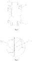
Fig. 1 illustrates a schematic structural diagram of an electronic expansion valve according to embodiment of this invention. -
Fig. 2 illustrates a cross-sectional diagram after press-fitting of a valve base and a guide sleeve inFig. 1 . -
Fig. 3 illustrates a schematic diagram of guiding the guide sleeve by a guide segment when the guide sleeve is put into the valve base inFig. 1 . -
Fig. 4 illustrates a partially enlarged diagram of A inFig. 3 . -
Fig. 5 illustrates a schematic diagram after the guide sleeve is press-fitted to the press-fit segment inFig. 1 . -
Fig. 6 illustrates a partially enlarged diagram of B inFig. 5 . -
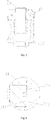
Fig. 7 illustrates a schematic structural diagram of the guide sleeve inFig. 1 . -
Fig. 8 illustrates a schematic structural diagram of the valve base inFig. 1 . -
Fig. 9 illustrates a schematic structural diagram of an electronic expansion valve according to another embodiment. -
Fig. 10 illustrates an assembly diagram of a first pipe and a valve base inFig. 9 . -
Fig. 11 illustrates a schematic structural diagram of a guide sleeve inFig. 9 . -
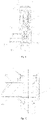
Fig. 12 illustrates a schematic structural diagram of an electronic expansion valve according to another embodiment. -
Fig. 13 illustrates a cross-sectional diagram of a second pipe and a valve base inFig. 12 . -
Fig. 14 illustrates an assembly diagram of a guide sleeve and the valve base inFig. 12 . -
Fig. 15 illustrates another assembly diagram of the guide sleeve and the valve base inFig. 12 . -
Fig. 16 illustrates an assembly diagram of the second pipe and the valve base inFig. 12 . -
Fig. 17 illustrates an assembly diagram of a first pipe and the valve base inFig. 12 . - The above drawings include the following reference signs:
10. housing; 11. casing; 12. valve base; 121. mounting hole; 121a. first segment; 121b. second segment; 121c. limiting boss; 122. body; 123. mounting boss; 123a. containing groove; 20. guide sleeve; 21. mounting boss; 211. third segment; 212. fourth segment; 213. welding ring groove; 22. nut guide segment; 23. limiting boss; 24. straight segment; 30. nut assembly; 40. rotor; 50. screw; 60. valve needle assembly; 70. first pipe; 80. limiting structure; 90. second pipe; 100. welding ring containing part; 110. welding ring. - Hereinafter, the technical solutions in the embodiments of this invention will be clearly and completely described below with reference to the accompanying drawings in the embodiments of this invention. It is apparent that the described embodiments are only part of the embodiments of this invention, and are not all of the embodiments. The following description of at least one exemplary embodiment is merely illustrative in nature and is not intended to limit this invention and uses thereof in any way. Based on the embodiments in this invention, all other embodiments obtained by those skilled in the art without inventive effort fall within the scope of protection of this invention.
- As shown in drawings, Embodiment 1 of this invention provides an electronic expansion valve. The electronic expansion valve includes a
housing 10, aguide sleeve 20, arotor 40, ascrew 50 and avalve needle assembly 60. Theguide sleeve 20 and thescrew 50 are both disposed in thehousing 10. Specifically, therotor 40 is rotatably disposed in thehousing 10, and therotor 40 is drivingly connected with thescrew 50. Thevalve needle assembly 60 is movably disposed in thehousing 10, and by connecting one end of thescrew 50 with thevalve needle assembly 60, thescrew 50 can drive thevalve needle assembly 60 to move axially, so that thevalve needle assembly 60 is used to open or block a valve port. A guide segment and a press-fit segment which are in communication with each other are disposed between an inner wall of thehousing 10 and an outer wall of theguide sleeve 20, and the spacing between theguide sleeve 20 and thehousing 10 located on the guide segment is greater than the spacing between theguide sleeve 20 and thehousing 10 located on the press-fit segment. Awelding ring groove 213 is also disposed between the inner wall of thehousing 10 and the outer wall of theguide sleeve 20, and thewelding ring groove 213 is in communication with the guide segment. Thewelding ring groove 213 is completely disposed in the guide segment, or thewelding ring groove 213 is partially disposed in the guide segment and partially disposed in the press-fit segment. In some embodiments, thewelding ring groove 213 is partially disposed in the guide segment and partially disposed in the press-fit segment, so that the solder can fully fill the gap, and the welding effect can be improved. - The spacing between the
guide sleeve 20 and thehousing 10 located on the guide segment is greater than the spacing between theguide sleeve 20 and thehousing 10 located on the press-fit segment, including the following three structures: - First structure: by expanding the inner diameter of a part of the inner wall of the
housing 10, the guide segment can be formed between the inner wall of thehousing 10 and the outer wall of theguide sleeve 20, and by enabling another part of the inner wall of thehousing 10 to be in interference fit with the outer wall of theguide sleeve 20, the press-fit segment can be formed between the inner wall of thehousing 10 and the outer wall of theguide sleeve 20; - Second structure: by reducing the outer diameter of a part of the outer wall of the
guide sleeve 20, the guide segment can be formed between the outer wall of theguide sleeve 20 and the inner wall of thehousing 10, and by enabling the other part of the outer wall of theguide sleeve 20 to be interference fit with the inner wall of thehousing 10, the press-fit segment can be formed between the outer wall of theguide sleeve 20 and the inner wall of thehousing 10; and - Third structure: by simultaneously expanding the inner diameter of a part of the inner wall of the
housing 10 and reducing the outer diameter of a part of the outer wall of theguide sleeve 20, the guide segment can be formed between the inner wall of thehousing 10 and the outer wall of theguide sleeve 20, and by enabling another part of the inner wall of thehousing 10 to be interference fit with another part of the outer wall of theguide sleeve 20, the press-fit segment can be formed between the inner wall of thehousing 10 and the outer wall of theguide sleeve 20. - In some embodiments, the first structure is used to enable the spacing between the
guide sleeve 20 and thehousing 10 located on the guide segment to be greater than the spacing between theguide sleeve 20 and thehousing 10 located on the press-fit segment. - By applying the electronic expansion valve provided in the present embodiment, when an electronic expansion valve is assembled, the
guide sleeve 20 and thehousing 10 can be assembled first. When theguide sleeve 20 is press-fitted to thehousing 10, the guide segment can position and guide theguide sleeve 20, so that theguide sleeve 20 can be mounted in thehousing 10, and the press-fit segment can realize the press-fitting of theguide sleeve 20 and thehousing 10. After the press-fitting is completed, the first pipe and the second pipe are respectively connected with thehousing 10. Since there is a gap between theguide sleeve 20 and thehousing 10 located on the guide segment, awelding ring groove 213 is disposed between the inner wall of thehousing 10 and the outer wall of theguide sleeve 20, and thewelding ring groove 213 is in communication with the guide segment, the welding process requirements for furnace welding are met, and theguide sleeve 20, the first pipe and the second pipe can be welded to thehousing 10 by means of integrated furnace welding. With the above structure, since theguide sleeve 20 is welded to thehousing 10 by means of furnace welding, and the first pipe and the second pipe can not affect the press-fitting of theguide sleeve 20, the coaxiality of theguide sleeve 20 and thehousing 10 can be ensured. - In some embodiments, due to complex technology and higher cost of laser welding, the first pipe, the second pipe and the
guide sleeve 20 are welded to thehousing 10 by means of integrated furnace welding, which can simplify the processing technology and reduce the processing cost. In some embodiments, in the art known to inventors, when theguide sleeve 20 is welded to thehousing 10 by means of laser welding, since there is a plurality of welding points between theguide sleeve 20 and thehousing 10, the welding process can not ensure the coaxiality of theguide sleeve 20 and thehousing 10. In the present embodiment, theguide sleeve 20 is welded to thehousing 10 by means of furnace welding, and the welding process can not affect the coaxiality of theguide sleeve 20 and thehousing 10, so that the accuracy of the device can be improved, and the sealing performance of the electronic expansion valve can be improved. - In some embodiments, the
housing 10 includes acasing 11 and avalve base 12, theguide sleeve 20 is disposed in thevalve base 12, and the guide segment and the press-fit segment are located between theguide sleeve 20 and thevalve base 12. The first pipe and the second pipe are both connected with thevalve base 12. - The
valve base 12 is provided with a mountinghole 121, theguide sleeve 20 is disposed in the mountinghole 121, and the mountinghole 121 has afirst segment 121a and asecond segment 121b which are connected with each other. In the present embodiment, an inner wall of thefirst segment 121a is matched with theguide sleeve 20 to form the guide segment, an inner wall of thesecond segment 121b is matched with theguide sleeve 20 to form the press-fit segment, and thefirst segment 121a is located above thesecond segment 121b. In other embodiments, thefirst segment 121a is located below thesecond segment 121b. - In some embodiments, the aperture of the
first segment 121a is greater than the aperture of thesecond segment 121b, so that the spacing between theguide sleeve 20 and thehousing 10 located on the guide segment is greater than the spacing between theguide sleeve 20 and thehousing 10 located on the press-fit segment. In some embodiments, the aperture of thefirst segment 121a is greater than the aperture of thesecond segment 121b by 0.02 mm to 0.08 mm. With the above structure, the spacing between theguide sleeve 20 and thefirst segment 121a is 0.01 mm to 0.04 mm, and theguide sleeve 20 and thesecond segment 121b are interference fit. - A mounting
boss 21 is disposed on theguide sleeve 20, the mountingboss 21 is disposed along a circumferential direction of a side wall of theguide sleeve 20, and the guide segment and the press-fit segment are formed between a side wall of the mountingboss 21 and the inner wall of the mountinghole 121. In some embodiments, the guide segment and the press-fit segment are formed between the side wall of the mountingboss 21 and the inner walls of thefirst segment 121a and thesecond segment 121b of the mountinghole 121. - In some embodiments, the mounting
boss 21 includes athird segment 211 and afourth segment 212, thethird segment 211 is disposed corresponding to thefirst segment 121a, and thefourth segment 212 is disposed corresponding to thesecond segment 121b. Thethird segment 211 is located above thefourth segment 212. - In some embodiments, the cross-sectional dimension of the
third segment 211 is equal to the cross-sectional dimension of thefourth segment 212. - In some embodiments, the
welding ring groove 213 is disposed on the mountingboss 21, thewelding ring groove 213 is located between thethird segment 211 and thefourth segment 212, and thewelding ring groove 213 is disposed along a circumferential direction of the side wall of the mountingboss 21. In some embodiments, one end of thewelding ring groove 213 is connected with thethird segment 211, and the other end of thewelding ring groove 213 is connected with thefourth segment 212. With the above structure, thewelding ring groove 213 can be used to place a welding ring, so as to complete the connection between theguide sleeve 20 and thehousing 10 by means of furnace welding. - A limiting
boss 121c is disposed in the mountinghole 121, and the limitingboss 121c is located on one side of thesecond segment 121b away from thefirst segment 121a. In some embodiments, one end of the limitingboss 121c is connected with thesecond segment 121b. By matching the limitingboss 121c with the mountingboss 21, the displacement of theguide sleeve 20 relative to thevalve base 12 can be limited, so as to prevent theguide sleeve 20 from going too deep into the mountinghole 121. - In some embodiments, the electronic expansion valve further includes a
nut assembly 30, theguide sleeve 20 includes anut guide segment 22, and thenut assembly 30 is disposed on thenut guide segment 22 in a sleeving manner. In some embodiments, thenut guide segment 22 is connected with the mountingboss 21 and located above the mountingboss 21. After the welding of theguide sleeve 20 and thehousing 10, thenut assembly 30 can be press-fitted to thenut guide segment 22 of theguide sleeve 20. During the press-fitting process, thenut guide segment 22 can position and guide thenut assembly 30. - The assembling steps of the device provided in the Embodiment 1 are:
- (1) the
guide sleeve 20 is put into thevalve base 12, and thefourth segment 212 of theguide sleeve 20 is in clearance fit with thefirst segment 121a of thevalve base 12, so as to position and guide theguide sleeve 20; - (2) the
guide sleeve 20 is press-fitted so that a lower surface of the mountingboss 21 is in contact with a step surface of the limitingboss 121c, and thefourth segment 212 of theguide sleeve 20 is tightly fitted with thesecond segment 121b of thevalve base 12. At this time, there is a gap of 0.01 mm to 0.04 mm on one side between thethird segment 211 of theguide sleeve 20 and thefirst segment 121a of thevalve base 12 as a welding seam, and a welding ring is placed in thewelding ring groove 213; and - (3) the first pipe and the second pipe are assembled on the
valve base 12, and the first pipe, the second pipe, theguide sleeve 20 and thevalve base 12 are welded together by means of integrated furnace welding. - Embodiment 2 of this invention provides an electronic expansion valve. Compared with the Embodiment 1, the electronic expansion valve provided in Embodiment 2 is different in that: in the present embodiment, the cross-sectional dimension of the
third segment 211 is less than or greater than the cross-sectional dimension of thefourth segment 212. In some embodiments, the cross-sectional dimension of thethird segment 211 is less than the cross-sectional dimension of thefourth segment 212, the guide segment is formed between thethird segment 211 and the inner wall of the mountinghole 121, and the press-fit segment is formed between thefourth segment 212 and the inner wall of the mountinghole 121, so that the spacing between theguide sleeve 20 and thehousing 10 located on the guide segment is greater than the spacing between theguide sleeve 20 and thehousing 10 located on the press-fit segment. In the present embodiment, thethird segment 211 is located above thefourth segment 212. In other embodiments, thethird segment 211 is located below thefourth segment 212. - In some embodiments, the cross-sectional dimension of the
third segment 211 is less than the cross-sectional dimension of thefourth segment 212 by 0.02 mm to 0.08 mm. With the above structure, the spacing between the inner wall of the mountinghole 121 and thethird segment 211 is 0.01 mm to 0.04 mm, and the inner wall of the mountinghole 121 and thefourth segment 212 are interference fit. The apertures of thefirst segment 121a and thesecond segment 121b of the mountinghole 121 are equal. - Embodiment 3 of this invention provides an electronic expansion valve. Compared with the Embodiment 1, the electronic expansion valve provided in Embodiment 3 is different in that: in this embodiment, the aperture of the
first segment 121a is greater than the aperture of thesecond segment 121b, the cross-sectional dimension of thethird segment 211 is less than the cross-sectional dimension of thefourth segment 212, the guide segment is formed between the inner wall of thefirst segment 121a and the outer wall of thethird segment 211, and the press-fit segment is formed between the inner wall of thesecond segment 121b and the outer wall of the fourth segment, so that the spacing between theguide sleeve 20 and thehousing 10 located on the guide segment is greater than the spacing between theguide sleeve 20 and thehousing 10 located on the press-fit segment. In the present embodiment, thefirst segment 121a is located above thesecond segment 121b, and thethird segment 211 is located above thefourth segment 212. In other embodiments, thefirst segment 121a is disposed below thesecond segment 121b, and thethird segment 211 is disposed below thefourth segment 212. - The electronic expansion valve provided in the above embodiment has the following beneficial effects:
- (1) when the
guide sleeve 20 and thehousing 10 are press-fitted, theguide sleeve 20 can be positioned by the guide segment, so that the press-fitting process is convenient; - (2) after the
guide sleeve 20 is press-fitted into thehousing 10, the first pipe and the second pipe are assembled on thehousing 10, and thehousing 10 assembled with the first pipe, the second pipe and theguide sleeve 20 is welded by means of integrated furnace welding, so that the process is simple and stable, and the coaxiality of the guide sleeve and the valve body can be effectively ensured; - (3) after the integrated furnace welding, the welding quality can be observed through the guide segment, and if there is solder seepage, it means that the welding seam is filled, and the welding method is judged to be reliable and efficient; and
- (4) due to the manner of furnace welding, both the
valve base 12 and theguide sleeve 20 is made of sus303, which can reduce the trial production difficulty and cost of thevalve base 12 and theguide sleeve 20. In the art known to inventors, since thevalve base 12 and theguide sleeve 20 are welded by means of laser welding, a stainless-steel material with higher strength needs to be used, and the cost is higher. - In the art known to inventors, an electronic expansion valve includes a housing, a first pipe and a second pipe, the housing is provided with an inlet hole and an outlet hole which are in communication with each other, the first pipe is arranged in the inlet hole and partially extends into the housing, a coolant can enter the housing from the inlet hole through the first pipe, and the second pipe is disposed corresponding to the outlet hole. In order to limit the length of the first pipe extending into the housing, a necked segment is arranged at one end of the first pipe close to the inlet hole, and by controlling the length of the necked segment, the length of the first pipe extending into the housing can be limited. However, in the art known to inventors, the length of the necked segment is difficult to ensure, and thus, the length of the first pipe extending into the housing cannot be accurately controlled. Furthermore, the necking of the first pipe will increase the flow resistance of the first pipe, which affects the use of the electronic expansion valve. Therefore, there is a problem that the art known to inventors cannot meet the use requirements.
- In order to solve the above problem, in another embodiment, different from the above embodiment, the
housing 10 has an inlet hole and an outlet hole which are in communication with each other, thevalve needle assembly 60 is penetrated in theguide sleeve 20, and thevalve needle assembly 60 is configured to open or close the outlet hole. The electronic expansion valve further includes afirst pipe 70 and a limitingstructure 80. Thefirst pipe 70 disposed in the inlet hole and partially extending into thehousing 10. the limitingstructure 80 is disposed between theguide sleeve 20 and thefirst pipe 70, wherein the limitingstructure 80 is configured to limit the length of thefirst pipe 70 extending into thehousing 10, so as to prevent thefirst pipe 70 from extending into thehousing 10 excessively. The limitingstructure 80 is disposed on theguide sleeve 20, or disposed on thefirst pipe 70, or simultaneously disposed on theguide sleeve 20 and thefirst pipe 70. - Applying the electronic expansion valve provided in the present embodiment, by arranging the limiting
structure 80 between theguide sleeve 20 and thefirst pipe 70, the limitingstructure 80 can be used to limit the length of thefirst pipe 70 extending into thehousing 10. In this way, the length of thefirst pipe 70 extending into thehousing 10 can be accurately controlled by the limitingstructure 80 without necking thefirst pipe 70, and the flow resistance of thefirst pipe 70 cannot be increased, so that the use requirements can be met. Furthermore, since thefirst pipe 70 does not need to be necked, the processing cost can be reduced. - In some embodiments, a limiting
boss 23 is disposed on theguide sleeve 20, the limitingboss 23 is disposed opposite to an end surface of thefirst pipe 70, and the limitingboss 23 forms the limitingstructure 80. When the length of thefirst pipe 70 extending into thehousing 10 reaches a preset dimension, the end surface of thefirst pipe 70 will abut against the limitingboss 23, so that the limitingboss 23 can be used to restrict the continuous movement of thefirst pipe 70 relative to thehousing 10. In other embodiments, a limiting boss is disposed on the end surface of thefirst pipe 70, and the limiting boss is higher than the end surface of thefirst pipe 70, which can also play a limiting role. - In some embodiments, the limiting
boss 23 is annularly disposed along the circumferential direction of theguide sleeve 20. With the above structure, the turning amount of theguide sleeve 20 can be reduced, the processing efficiency can be improved, the service life of a cutter can be prolonged, and the cost can be reduced. - In order to prevent the limiting
boss 23 from blocking the flow of the coolant, the limitingboss 23 is located above the axis of thefirst pipe 70. In some embodiments, a lower end surface of the limitingboss 23 is located above the axis of thefirst pipe 70. In the present embodiment, the lower end surface of the limitingboss 23 is flush with the inner wall of thefirst pipe 70, so that thefirst pipe 70 can be limited by the limitingboss 23, and the flow capacity of the coolant can be ensured to the maximum extent at the same time. - In some embodiments, the
guide sleeve 20 has astraight segment 24, the limitingboss 23 is located above thestraight segment 24, and a cross-sectional dimension of thestraight segment 24 is less than a cross-sectional dimension of the limitingboss 23. In some embodiments, there is a spacing between thestraight segment 24 and the end surface of thefirst pipe 70, so that the resistance of the coolant entering thefirst pipe 70 formed by theguide sleeve 20 can be reduced, and the flow capacity is stronger. - In order for the solder to smoothly flow between the
first pipe 70 and theguide sleeve 20, a flow guide structure is disposed between thefirst pipe 70 and theguide sleeve 20, and the flow guide structure is configured to circulate the solder, so that the welding effect can be improved, and it is convenient to detect the welding quality. - In some embodiments, a flow guide groove is disposed on an end surface of the
first pipe 70 extending into thehousing 10, and the flow guide groove forms the flow guide structure. Embossing may also be disposed on the end surface of thefirst pipe 70, and the flow of the solder is guided by the embossing. - In some embodiments, since in the art known to inventors, the first pipe is provided with a necked structure, when the first pipe and the
housing 10 are welded, the flow of the solder can only be observed on the outside of the first pipe, and the welding effect cannot be accurately judged. In the present embodiment, since thefirst pipe 70 is a straight pipe, the flow of the solder can be observed on the outside of thefirst pipe 70 and at a pipe orifice of thefirst pipe 70 at the same time, the welding effect can be accurately judged, and the welding quality can be improved. - In some embodiments, the
housing 10 includes acasing 11 and avalve base 12, theguide sleeve 20 is arranged in thevalve base 12, the inlet hole is disposed on the side wall of thevalve base 12, and thefirst pipe 70 is penetrated on thevalve base 12. The outlet hole is also disposed on thevalve base 12. - In some embodiments, the outlet hole is arranged corresponding to the valve port.
- In some embodiments, the
first pipe 70 and thehousing 10 is welded by means of integrated furnace welding. - The electronic expansion valve provided in this embodiment has the following beneficial effects:
- (1) by arranging the limiting
boss 23 on theguide sleeve 20, the limitingboss 23 can be used to limit the length of thefirst pipe 70 extending into thehousing 10, and thefirst pipe 70 does not need to be necked, so that the cost can be reduced; - (2) since the first pipe does not need to be necked, the flow resistance can be reduced, and the flow capacity can be improved;
- (3) the turning amount of the
guide sleeve 20 is relatively small, the processing efficiency can be improved, the service life of a cutter can be prolonged, and the cost can be reduced; - (4) there is a diameter difference between the limiting
boss 23 and thestraight segment 24 of theguide sleeve 20, so that the resistance of theguide sleeve 20 to the coolant entering thefirst pipe 70 can be reduced, and the flow capacity can be further improved; and - (5) the flow of the solder can be observed on the outside of the
first pipe 70 and at a pipe orifice of thefirst pipe 70 at the same time, so that the welding effect can be accurately judged, and the welding quality can be improved. - In the art known to inventors, in order to connect the second pipe with the housing, first, the second pipe is sleeved on the mounting boss, then, a welding ring is sleeved on the outside of the second pipe, and the connection is completed by means of welding. During welding, the welding quality can be detected through a pipe orifice of the second pipe away from a welding end. However, in the art known to inventors, it is difficult for an employee to accurately judge the welding quality of the welding end from the pipe orifice away from the welding end. Furthermore, when the second pipe is a bent pipe, the employee cannot detect the welding quality. Therefore, the art known to inventors has the problem that it is difficult to detect the welding quality.
- In order to solve the above problem, in another embodiment, different from the Embodiment 1, the
housing 10 includes acasing 11 and avalve base 12 which are connected with each other, thevalve base 12 includes abody 122 and a mountingboss 123, the mountingboss 123 is disposed at one end of thebody 122 away from thecasing 11, and the mountingboss 123 is provided with a valve port. The electronic expansion valve further includes: asecond pipe 90 which sleeved on the mountingboss 123. A weldingring containing part 100 is formed between an inner wall of thesecond pipe 90 and an outer side wall of the mountingboss 123, and the weldingring containing part 100 is configured to place awelding ring 110. The weldingring containing part 100 is disposed on the inner wall of thesecond pipe 90, or disposed on the outer side wall of the mountingboss 123, or simultaneously disposed on the inner wall of thesecond pipe 90 and the outer side wall of the mountingboss 123. - Applying the electronic expansion valve provided in the present embodiment, since the
welding ring 110 is arranged inside thesecond pipe 90, when thesecond pipe 90 is welded, by observing from the outside of thesecond pipe 90 whether there is solder leaking from the space between thesecond pipe 90 and thevalve base 12, the welding quality can be accurately judged and can be detected by the employee conveniently. Furthermore, the judgment of the welding quality is not limited by a pipe shape of thesecond pipe 90, and a bent pipe can be judged. Since less solder is stacked on the outside of thesecond pipe 90 after welding, the positioning and press-fitting of the electronic expansion valve can be effectively ensured. - In some embodiments, the welding
ring containing part 100 is disposed on the mountingboss 123. The weldingring containing part 100 is disposed in the middle of the mountingboss 123, or disposed at two ends of the mountingboss 123. By disposing the weldingring containing part 100 on the mountingboss 123, the weldingring containing part 100 can be processed conveniently, and the processing cost can be reduced. - In some embodiments, a containing
groove 123a is disposed on the outer side wall of the mountingboss 123, the containinggroove 123a is annularly disposed along the circumferential direction of the mountingboss 123, and the containinggroove 123a is configured to form the weldingring containing part 100. The containinggroove 123a is disposed in the middle of the mountingboss 123, or disposed at two ends of the mountingboss 123. Moreover, by arranging the containinggroove 123a, the processing is convenient. - In some embodiments, the containing
groove 123a is located at one end of the mountingboss 123 away from thebody 122. With the above structure, only one end of the mountingboss 123 away from thebody 122 needs to be turned to form the containinggroove 123a, so that the processing cost can be further reduced, and thewelding ring 110 can be placed conveniently. - In order for the solder to smoothly flow between the
second pipe 90 and the mountingboss 123, a flow guide structure is disposed between thesecond pipe 90 and the mountingboss 123, and the flow guide structure is configured to circulate the solder, so that the welding effect can be improved, and it is convenient to detect the welding quality. - In some embodiments, a flow guide groove is disposed on the inner wall of the
second pipe 90, and the flow guide groove forms the flow guide structure. Embossing may also be disposed on the end surface of thesecond pipe 90, and the flow of the solder is guided by the embossing. - The electronic expansion valve provided in this embodiment has the following beneficial effects:
- (1) after the welding of the
second pipe 90 and thehousing 10 is completed, the connecting part between thesecond pipe 90 and thevalve base 12 can be observed from the outside of thesecond pipe 90, and if there is solder in this region, it means that the welding of thesecond pipe 90 and thevalve base 12 has been completed through the solder; - (2) the judgment of the welding quality is not affected by a shape of the
second pipe 90, and a bent pipe can be judged; - (3) after the welding of the
second pipe 90 and thehousing 10, less solder is stacked on the outer wall of thesecond pipe 90 connected with thevalve base 12, so that subsequent positioning and press-fitting of the device can be effectively ensured; and - (4) since the amount of the stacked solder is reduced, the usage amount of the solder can be reduced, and the cost can be reduced.
- The above embodiments are merely some embodiments of this invention and are not intended to limit this invention. It will be apparent to those skilled in the art that various modifications and changes may be made in this invention. Any modification, equivalent replacement and improvement made within the spirit and principle of this invention shall be included in the protection scope of this invention.
Claims (20)
- An electronic expansion valve, wherein the electronic expansion valve comprises:a housing (10);a guide sleeve (20), disposed in the housing (10);a rotor (40), rotatably disposed in the housing (10);a screw (50), disposed in the housing (10), the rotor (40) being drivingly connected with the screw (50); anda valve needle assembly (60), movably disposed in the housing (10), one end of the screw (50) being connected with the valve needle assembly (60) so as to drive the valve needle assembly (60) to move axially by the screw (50),wherein a guide segment and a press-fit segment which are in communication with each other are disposed between an inner wall of the housing (10) and an outer wall of the guide sleeve (20), a spacing between the guide sleeve (20) and the housing (10) located on the guide segment is greater than a spacing between the guide sleeve (20) and the housing (10) located on the press-fit segment, a welding ring groove (213) is disposed between the inner wall of the housing (10) and the outer wall of the guide sleeve (20), and the welding ring groove (213) is in communication with the guide segment.
- The electronic expansion valve as claimed in claim 1, wherein the housing (10) comprises a casing (11) and a valve base (12), the guide sleeve (20) is disposed in the valve base (12), and the guide segment and the press-fit segment are located between the guide sleeve (20) and the valve base (12).
- The electronic expansion valve as claimed in claim 2, wherein the valve base (12) is provided with a mounting hole (121), the guide sleeve (20) is disposed in the mounting hole (121), the mounting hole (121) has a first segment (121a) and a second segment (121b) which are connected with each other, an inner wall of the first segment (121a) is matched with the guide sleeve (20) to form the guide segment, and an inner wall of the second segment (121b) is matched with the guide sleeve (20) to form the press-fit segment.
- The electronic expansion valve as claimed in claim 3, wherein a mounting boss (21) is disposed on the guide sleeve (20), the mounting boss (21) is disposed along a circumferential direction of a side wall of the guide sleeve (20), and the guide segment and the press-fit segment are formed between a side wall of the mounting boss (21) and an inner wall of the mounting hole (121).
- The electronic expansion valve as claimed in claim 4, wherein the mounting boss (21) comprises a third segment (211) and a fourth segment (212), the third segment (211) is disposed corresponding to the first segment (121a), and the fourth segment (212) is disposed corresponding to the second segment (121b).
- The electronic expansion valve as claimed in claim 5, wherein the welding ring groove (213) is disposed on the mounting boss (21), the welding ring groove (213) is located between the third segment (211) and the fourth segment (212), and the welding ring groove (213) is disposed along a circumferential direction of the side wall of the mounting boss (21).
- The electronic expansion valve as claimed in claim 4, wherein a limiting boss (121c) is disposed in the mounting hole (121), the limiting boss (121c) is located on one side of the second segment (121b) away from the first segment (121a), and the limiting boss (121c) is matched with the mounting boss (21) to limit a displacement of the guide sleeve (20) relative to the valve base (12).
- The electronic expansion valve as claimed in claim 1, wherein the electronic expansion valve further comprises a nut assembly (30), the guide sleeve (20) comprises a nut guide segment (22), and the nut assembly (30) is disposed on the nut guide segment (22) in a sleeving manner.
- The electronic expansion valve as claimed in claim 1, wherein the housing (10) has an inlet hole and an outlet hole which are in communication with each other, the valve needle assembly (60) is penetrated in the guide sleeve (20), and the valve needle assembly (60) is configured to open or close the outlet hole; and the electronic expansion valve further comprises:a first pipe (70), disposed in the inlet hole and partially extending into the housing (10); anda limiting structure (80), disposed between the guide sleeve (20) and the first pipe (70), wherein the limiting structure (80) is configured to limit a length of the first pipe (70) extending into the housing (10).
- The electronic expansion valve as claimed in claim 9, wherein a limiting boss (23) is disposed on the guide sleeve (20), and the limiting boss (23) is disposed opposite to an end surface of the first pipe (70).
- The electronic expansion valve as claimed in claim 10, wherein the limiting boss (23) is annularly disposed along a circumferential direction of the guide sleeve (20).
- The electronic expansion valve as claimed in claim 10, wherein the guide sleeve (20) has a straight segment (24), the limiting boss (23) is located above the straight segment (24), a cross-sectional dimension of the straight segment (24) is less than a cross-sectional dimension of the limiting boss (23), and a spacing is formed between the straight segment (24) and the end surface of the first pipe (70).
- The electronic expansion valve as claimed in claim 9, wherein a flow guide structure is disposed between the first pipe (70) and the guide sleeve (20), and the flow guide structure is configured to circulate solder.
- The electronic expansion valve as claimed in claim 13, wherein a flow guide groove is disposed on an end surface of the first pipe (70) extending into the housing (10).
- The electronic expansion valve as claimed in claim 1, wherein the housing (10) comprises a casing (11) and a valve base (12) which are connected with each other, the valve base (12) comprises a body (122) and a mounting boss (123), the mounting boss (123) is disposed at one end of the body (122) away from the casing (11), and a valve port is disposed on the mounting boss (123); and the electronic expansion valve further comprises:
a second pipe (90), sleeved on the mounting boss (123), wherein a welding ring containing part (100) is formed between an inner wall of the second pipe (90) and an outer side wall of the mounting boss (123), and the welding ring containing part (100) is configured to place a welding ring (110) . - The electronic expansion valve as claimed in claim 15, wherein the welding ring containing part (100) is disposed on the mounting boss (123).
- The electronic expansion valve as claimed in claim 16, wherein a containing groove (123a) is disposed on the outer side wall of the mounting boss (123), the containing groove (123a) is annularly disposed along a circumferential direction of the mounting boss (123), and the containing groove (123a) is configured to form the welding ring containing part (100).
- The electronic expansion valve as claimed in claim 17, wherein the containing groove (123a) is located at one end of the mounting boss (123) away from the body (122).
- The electronic expansion valve as claimed in claim 15, wherein a flow guide structure is disposed between the second pipe (90) and the mounting boss (123), and the flow guide structure is configured to circulate solder.
- The electronic expansion valve as claimed in claim 19, wherein a flow guide groove is disposed on the inner wall of the second pipe (90).
Applications Claiming Priority (4)
| Application Number | Priority Date | Filing Date | Title |
|---|---|---|---|
| CN201921637697.8U CN210920141U (en) | 2019-09-27 | 2019-09-27 | Electronic expansion valve |
| CN201921636034.4U CN210920266U (en) | 2019-09-27 | 2019-09-27 | Electronic expansion valve |
| CN201910927066.8A CN112576769B (en) | 2019-09-27 | 2019-09-27 | Electronic expansion valve |
| PCT/CN2020/086494 WO2021057019A1 (en) | 2019-09-27 | 2020-04-23 | Electronic expansion valve |
Publications (2)
| Publication Number | Publication Date |
|---|---|
| EP4036443A1 true EP4036443A1 (en) | 2022-08-03 |
| EP4036443A4 EP4036443A4 (en) | 2023-10-25 |
Family
ID=75165526
Family Applications (1)
| Application Number | Title | Priority Date | Filing Date |
|---|---|---|---|
| EP20868592.5A Pending EP4036443A4 (en) | 2019-09-27 | 2020-04-23 | Electronic expansion valve |
Country Status (5)
| Country | Link |
|---|---|
| US (1) | US12092381B2 (en) |
| EP (1) | EP4036443A4 (en) |
| JP (1) | JP7349514B2 (en) |
| KR (1) | KR102418213B1 (en) |
| WO (1) | WO2021057019A1 (en) |
Families Citing this family (7)
| Publication number | Priority date | Publication date | Assignee | Title |
|---|---|---|---|---|
| CN210372066U (en) * | 2019-06-14 | 2020-04-21 | 浙江盾安禾田金属有限公司 | Electronic expansion valve |
| USD1028175S1 (en) * | 2019-06-28 | 2024-05-21 | Danfoss A/S | Expansion valve |
| CN114352730A (en) * | 2020-10-12 | 2022-04-15 | 浙江盾安人工环境股份有限公司 | Flow regulating valve |
| CN116066581B (en) * | 2021-10-29 | 2026-02-06 | 浙江三花智能控制股份有限公司 | Electric valve |
| CN215983356U (en) * | 2021-08-31 | 2022-03-08 | 浙江盾安人工环境股份有限公司 | Electronic expansion valve |
| CN120991126A (en) * | 2021-10-13 | 2025-11-21 | 浙江三花智能控制股份有限公司 | Valve device |
| KR102705928B1 (en) * | 2022-10-14 | 2024-09-11 | 주식회사 유니크 | Manifold for heat pump system of electric vehicle |
Family Cites Families (16)
| Publication number | Priority date | Publication date | Assignee | Title |
|---|---|---|---|---|
| JP2001241562A (en) | 2000-03-01 | 2001-09-07 | Pacific Ind Co Ltd | Control valve |
| CN100510580C (en) * | 2004-12-15 | 2009-07-08 | 株式会社鹭宫制作所 | Electric control valve |
| CN102734476B (en) | 2011-04-02 | 2014-09-17 | 浙江三花股份有限公司 | Electronic expansion valve |
| WO2013127276A1 (en) * | 2012-02-28 | 2013-09-06 | 艾默生环境优化技术(苏州)有限公司 | Electronic expansion valve |
| CN103388939B (en) | 2012-05-11 | 2016-06-01 | 浙江三花股份有限公司 | A kind of electric expansion valve |
| KR101427137B1 (en) | 2012-10-29 | 2014-08-07 | 그린산업 주식회사 | Electronic expansion valve |
| CN107975629A (en) * | 2016-10-25 | 2018-05-01 | 盾安环境技术有限公司 | A kind of air conditioning system for vehicle electric expansion valve |
| CN108343749B (en) | 2017-01-24 | 2021-12-21 | 浙江盾安机械有限公司 | Electronic expansion valve |
| JP6726116B2 (en) * | 2017-01-31 | 2020-07-22 | 株式会社鷺宮製作所 | Motorized valve and refrigeration cycle system |
| CN108999990B (en) | 2017-06-07 | 2021-07-20 | 浙江盾安禾田金属有限公司 | Electronic expansion valve |
| CN208431390U (en) | 2018-05-08 | 2019-01-25 | 艾默生环境优化技术(苏州)有限公司 | Valve needle assembly and electronic expansion valve with same |
| CN208281509U (en) | 2018-06-13 | 2018-12-25 | 浙江三花智能控制股份有限公司 | Solenoid valve |
| CN209196130U (en) | 2018-08-02 | 2019-08-02 | 浙江盾安禾田金属有限公司 | Air-conditioning and its electric expansion valve |
| KR102794332B1 (en) | 2018-08-17 | 2025-04-11 | 제지앙 둔안 아트피셜 인바이런먼트 컴퍼니 리미티드 | Electronic expansion valve |
| CN209012510U (en) | 2018-08-17 | 2019-06-21 | 浙江盾安禾田金属有限公司 | Electric expansion valve |
| CN209180369U (en) | 2018-08-21 | 2019-07-30 | 浙江盾安禾田金属有限公司 | Electric expansion valve |
-
2020
- 2020-04-23 JP JP2021577296A patent/JP7349514B2/en active Active
- 2020-04-23 KR KR1020227002807A patent/KR102418213B1/en active Active
- 2020-04-23 US US17/763,725 patent/US12092381B2/en active Active
- 2020-04-23 WO PCT/CN2020/086494 patent/WO2021057019A1/en not_active Ceased
- 2020-04-23 EP EP20868592.5A patent/EP4036443A4/en active Pending
Also Published As
| Publication number | Publication date |
|---|---|
| WO2021057019A1 (en) | 2021-04-01 |
| KR20220014913A (en) | 2022-02-07 |
| KR102418213B1 (en) | 2022-07-07 |
| JP2022549987A (en) | 2022-11-30 |
| JP7349514B2 (en) | 2023-09-22 |
| US20220341638A1 (en) | 2022-10-27 |
| US12092381B2 (en) | 2024-09-17 |
| EP4036443A4 (en) | 2023-10-25 |
Similar Documents
| Publication | Publication Date | Title |
|---|---|---|
| US12092381B2 (en) | Electronic expansion valve and assembling method of electronic expansion valve | |
| CN112855953B (en) | Electronic expansion valve | |
| CN211145371U (en) | Electronic expansion valve | |
| CN103052999B (en) | Electromagnetic drive unit and manufacture method thereof | |
| EP3974689B1 (en) | Electronic expansion valve | |
| EP4621269A1 (en) | Electronic expansion valve and assembly method | |
| CN112576769B (en) | Electronic expansion valve | |
| CN102825395A (en) | Brazing structure for connecting pipe and valve seat | |
| CN104807259A (en) | Electronic expansion valve | |
| CN209294521U (en) | Valve module, motor-driven valve and thermal management assemblies | |
| CN213420014U (en) | One-way valve | |
| CN210920266U (en) | Electronic expansion valve | |
| KR100567737B1 (en) | Solenoid valve | |
| CN222733056U (en) | Electronic expansion valve | |
| CN209294429U (en) | Motor-driven valve and thermal management assemblies | |
| US10107243B2 (en) | Fuel injection valve | |
| CN212169329U (en) | A welding tool for controlling the air gap of an electronic expansion valve motor | |
| KR102809320B1 (en) | Electronic expansion valve | |
| CN204669146U (en) | A kind of electric machine main shaft of electric automobile | |
| CN204992801U (en) | Shielding motor stator housing subassembly | |
| CN220770106U (en) | All-terrain vehicle connecting shaft lubrication suite | |
| CN220771348U (en) | Muffler assembly | |
| CN100432510C (en) | Installing structure of water supply valve | |
| WO2022083623A1 (en) | One-way valve | |
| CN214641577U (en) | Tool for assembling aviation case plug |
Legal Events
| Date | Code | Title | Description |
|---|---|---|---|
| STAA | Information on the status of an ep patent application or granted ep patent |
Free format text: STATUS: THE INTERNATIONAL PUBLICATION HAS BEEN MADE |
|
| PUAI | Public reference made under article 153(3) epc to a published international application that has entered the european phase |
Free format text: ORIGINAL CODE: 0009012 |
|
| STAA | Information on the status of an ep patent application or granted ep patent |
Free format text: STATUS: REQUEST FOR EXAMINATION WAS MADE |
|
| 17P | Request for examination filed |
Effective date: 20220401 |
|
| AK | Designated contracting states |
Kind code of ref document: A1 Designated state(s): AL AT BE BG CH CY CZ DE DK EE ES FI FR GB GR HR HU IE IS IT LI LT LU LV MC MK MT NL NO PL PT RO RS SE SI SK SM TR |
|
| DAV | Request for validation of the european patent (deleted) | ||
| DAX | Request for extension of the european patent (deleted) | ||
| A4 | Supplementary search report drawn up and despatched |
Effective date: 20230926 |
|
| RIC1 | Information provided on ipc code assigned before grant |
Ipc: F16K 1/00 20060101AFI20230920BHEP |
|
| STAA | Information on the status of an ep patent application or granted ep patent |
Free format text: STATUS: EXAMINATION IS IN PROGRESS |
|
| 17Q | First examination report despatched |
Effective date: 20250408 |