EP4036397B1 - Fuel injection valve, and internal combustion engine provided with fuel injection valve - Google Patents
Fuel injection valve, and internal combustion engine provided with fuel injection valve Download PDFInfo
- Publication number
- EP4036397B1 EP4036397B1 EP20868044.7A EP20868044A EP4036397B1 EP 4036397 B1 EP4036397 B1 EP 4036397B1 EP 20868044 A EP20868044 A EP 20868044A EP 4036397 B1 EP4036397 B1 EP 4036397B1
- Authority
- EP
- European Patent Office
- Prior art keywords
- injection port
- injection
- fuel
- fuel injector
- circle
- Prior art date
- Legal status (The legal status is an assumption and is not a legal conclusion. Google has not performed a legal analysis and makes no representation as to the accuracy of the status listed.)
- Active
Links
Images


Classifications
-
- F—MECHANICAL ENGINEERING; LIGHTING; HEATING; WEAPONS; BLASTING
- F02—COMBUSTION ENGINES; HOT-GAS OR COMBUSTION-PRODUCT ENGINE PLANTS
- F02M—SUPPLYING COMBUSTION ENGINES IN GENERAL WITH COMBUSTIBLE MIXTURES OR CONSTITUENTS THEREOF
- F02M61/00—Fuel-injectors not provided for in groups F02M39/00 - F02M57/00 or F02M67/00
- F02M61/16—Details not provided for in, or of interest apart from, the apparatus of groups F02M61/02 - F02M61/14
- F02M61/18—Injection nozzles, e.g. having valve seats; Details of valve member seated ends, not otherwise provided for
- F02M61/1806—Injection nozzles, e.g. having valve seats; Details of valve member seated ends, not otherwise provided for characterised by the arrangement of discharge orifices, e.g. orientation or size
-
- F—MECHANICAL ENGINEERING; LIGHTING; HEATING; WEAPONS; BLASTING
- F02—COMBUSTION ENGINES; HOT-GAS OR COMBUSTION-PRODUCT ENGINE PLANTS
- F02M—SUPPLYING COMBUSTION ENGINES IN GENERAL WITH COMBUSTIBLE MIXTURES OR CONSTITUENTS THEREOF
- F02M61/00—Fuel-injectors not provided for in groups F02M39/00 - F02M57/00 or F02M67/00
- F02M61/04—Fuel-injectors not provided for in groups F02M39/00 - F02M57/00 or F02M67/00 having valves, e.g. having a plurality of valves in series
- F02M61/10—Other injectors with elongated valve bodies, i.e. of needle-valve type
-
- F—MECHANICAL ENGINEERING; LIGHTING; HEATING; WEAPONS; BLASTING
- F02—COMBUSTION ENGINES; HOT-GAS OR COMBUSTION-PRODUCT ENGINE PLANTS
- F02M—SUPPLYING COMBUSTION ENGINES IN GENERAL WITH COMBUSTIBLE MIXTURES OR CONSTITUENTS THEREOF
- F02M61/00—Fuel-injectors not provided for in groups F02M39/00 - F02M57/00 or F02M67/00
- F02M61/14—Arrangements of injectors with respect to engines; Mounting of injectors
-
- F—MECHANICAL ENGINEERING; LIGHTING; HEATING; WEAPONS; BLASTING
- F02—COMBUSTION ENGINES; HOT-GAS OR COMBUSTION-PRODUCT ENGINE PLANTS
- F02M—SUPPLYING COMBUSTION ENGINES IN GENERAL WITH COMBUSTIBLE MIXTURES OR CONSTITUENTS THEREOF
- F02M61/00—Fuel-injectors not provided for in groups F02M39/00 - F02M57/00 or F02M67/00
- F02M61/16—Details not provided for in, or of interest apart from, the apparatus of groups F02M61/02 - F02M61/14
- F02M61/18—Injection nozzles, e.g. having valve seats; Details of valve member seated ends, not otherwise provided for
- F02M61/1806—Injection nozzles, e.g. having valve seats; Details of valve member seated ends, not otherwise provided for characterised by the arrangement of discharge orifices, e.g. orientation or size
- F02M61/1813—Discharge orifices having different orientations with respect to valve member direction of movement, e.g. orientations being such that fuel jets emerging from discharge orifices collide with each other
-
- F—MECHANICAL ENGINEERING; LIGHTING; HEATING; WEAPONS; BLASTING
- F02—COMBUSTION ENGINES; HOT-GAS OR COMBUSTION-PRODUCT ENGINE PLANTS
- F02M—SUPPLYING COMBUSTION ENGINES IN GENERAL WITH COMBUSTIBLE MIXTURES OR CONSTITUENTS THEREOF
- F02M61/00—Fuel-injectors not provided for in groups F02M39/00 - F02M57/00 or F02M67/00
- F02M61/16—Details not provided for in, or of interest apart from, the apparatus of groups F02M61/02 - F02M61/14
- F02M61/18—Injection nozzles, e.g. having valve seats; Details of valve member seated ends, not otherwise provided for
- F02M61/1806—Injection nozzles, e.g. having valve seats; Details of valve member seated ends, not otherwise provided for characterised by the arrangement of discharge orifices, e.g. orientation or size
- F02M61/1826—Discharge orifices having different sizes
-
- F—MECHANICAL ENGINEERING; LIGHTING; HEATING; WEAPONS; BLASTING
- F02—COMBUSTION ENGINES; HOT-GAS OR COMBUSTION-PRODUCT ENGINE PLANTS
- F02M—SUPPLYING COMBUSTION ENGINES IN GENERAL WITH COMBUSTIBLE MIXTURES OR CONSTITUENTS THEREOF
- F02M61/00—Fuel-injectors not provided for in groups F02M39/00 - F02M57/00 or F02M67/00
- F02M61/16—Details not provided for in, or of interest apart from, the apparatus of groups F02M61/02 - F02M61/14
- F02M61/18—Injection nozzles, e.g. having valve seats; Details of valve member seated ends, not otherwise provided for
- F02M61/1806—Injection nozzles, e.g. having valve seats; Details of valve member seated ends, not otherwise provided for characterised by the arrangement of discharge orifices, e.g. orientation or size
- F02M61/1833—Discharge orifices having changing cross sections, e.g. being divergent
-
- F—MECHANICAL ENGINEERING; LIGHTING; HEATING; WEAPONS; BLASTING
- F02—COMBUSTION ENGINES; HOT-GAS OR COMBUSTION-PRODUCT ENGINE PLANTS
- F02M—SUPPLYING COMBUSTION ENGINES IN GENERAL WITH COMBUSTIBLE MIXTURES OR CONSTITUENTS THEREOF
- F02M61/00—Fuel-injectors not provided for in groups F02M39/00 - F02M57/00 or F02M67/00
- F02M61/16—Details not provided for in, or of interest apart from, the apparatus of groups F02M61/02 - F02M61/14
- F02M61/18—Injection nozzles, e.g. having valve seats; Details of valve member seated ends, not otherwise provided for
- F02M61/1806—Injection nozzles, e.g. having valve seats; Details of valve member seated ends, not otherwise provided for characterised by the arrangement of discharge orifices, e.g. orientation or size
- F02M61/1846—Dimensional characteristics of discharge orifices
Definitions
- the present invention relates to a fuel injector that injects fuel into an internal combustion engine and to an internal combustion engine including the fuel injector.
- a fuel injector is configured to be provided with plural injection ports for injecting fuel in a tip portion of the fuel injector, to shut off injection of the fuel from the injection ports into a combustion chamber of the internal combustion engine when a valve body and a valve seat surface provided on the inside of the fuel injector abut each other, and to inject the fuel from the injection ports into the combustion chamber when the valve body and the valve seat surface separate from each other (for example, see PTL 1).
- a fuel injection valve has a nozzle section with a first imaginary circle which is defined approximately coaxially to a center axis of the nozzle section, and has a first arc with injection orifices and a first arc without injection orifices.
- PTL 3 describes a nozzle assembly for a fuel injector for injecting fuel into a combustion chamber of an internal combustion engine.
- a fuel flow is separated from a side surface (an inner wall surface) of the injection port at the time when the fuel is injected from the injection port. Consequently, some of the fuel injected from the injection port possibly spatters around the injection port, produces droplets, and adheres to an outer circumferential wall surface at a tip of the fuel injector. When the fuel produces the droplets and adheres to the tip of the fuel injector, incomplete combustion occurs, which is a cause of generation of unburned particle matters.
- the present invention has been made with the above-described problem as the background and therefore has a purpose of providing a fuel injector capable of reducing separation of a fuel flow in an injection port during fuel injection.
- the fuel injector according to the present invention is the fuel injector (30) that injects fuel into the internal combustion engine (10) from the plural injection ports (31a to 31f).
- the plural injection ports (31a to 31f) are provided in plural on the first circle with the first radius (R1) and on the second circle with the larger second diameter (R2) than the first radius (R1), and include: the first injection port (31a), a center of an opening of which is provided on the first circle; and the second injection port (31c), a center of an opening of which is provided on the second circle on an opposite side of a tangent of the first circle passing the center of the opening of the first injection port (31a) from a center axis of the fuel injection (30), that, when seen in a cross section on the shortest line connecting the center of the first injection port (31a) and the center of the second injection port (31c), of edges on an injection upstream side of the first injection port (31a), at least the edge (32a) on a side
- the flux of the fuel flowing into the first injection port (31a) from the edge (32a) on the side not opposing each other can be less likely to be separated from the inner wall surface of the first injection port.
- the second injection port (31c) is provided on the second circle on the opposite side of the tangent (F-F) of the first circle from the center axis (CF1) of the fuel injector (30)
- a flux of the fuel flowing into the first injection port (31a) from the edge (32b) on a side opposing the second injection port (31c) can be less likely to be separated from the inner wall surface
- the internal combustion engine (10) is configured to include the above-described fuel injector (30). According to such a configuration, since the internal combustion engine (10) includes the above-described fuel injector (30), it is possible to suppress the separation of the fuel flow in the first injection port (31a) at least during fuel injection, and it is possible to reduce adhesion of the fuel to a tip of the fuel injector (30) and the like, which is a cause of a deposit produced by incomplete combustion.
- the present invention may only have the matters used to define the invention and described in the claims of the present invention, or may have a configuration other than the matters used to define the invention in addition to the matters used to define the invention and described in the claims of the present invention.
- the fuel injector according to this embodiment can be applied as a fuel injector that injects fuel in an internal combustion engine (for example, a gasoline engine, a diesel engine, or the like).
- an internal combustion engine including the fuel injector according to the present invention for example, an internal combustion engine that uses gasoline as the fuel can be applied as an internal combustion engine for a vehicle, a power generator, or the like.
- a description will be made on an example in which the gasoline internal combustion engine for a vehicle is used as the internal combustion engine.
- the present invention is not particularly limited thereto.
- the internal combustion engine 10 includes: an engine body 20 that forms a combustion chamber 21; a fuel injector 30 that injects fuel into the combustion chamber 21; an ignition plug 40 that generates spark discharge in the combustion chamber 21; an intake valve 50 that connects/disconnects the combustion chamber 21 to/from an intake passage 24; an exhaust valve 60 that connects/disconnects the combustion chamber 21 to/from an exhaust passage 25; a piston 70 that operates linearly in conjunction with combustion of air-fuel mixture, which contains the fuel and air, in the combustion chamber 21; a connecting rod 80 and a crankshaft (not illustrated) that convert the linear operation of the piston 70 into rotational motion; a fuel supplier (not illustrated) that supplies the fuel from a fuel tank (not illustrated), which stores the fuel, to the fuel injector 30; and the like.
- the engine body 20 includes a cylinder head 22 and a cylinder block 23, and the cylinder head 22 and the cylinder block 23 form the combustion chamber 21.
- a first attachment hole 26 is formed near a joint section between the cylinder head 22 and the intake passage 24, and communicates with the combustion chamber 21 from outside of the cylinder head 22.
- the fuel injector 30 is inserted in the first attachment hole 26.
- a second attachment hole 27 is formed between an attachment position of the intake valve 50 and an attachment position of the exhaust valve 60, and communicates with the combustion chamber 21 from the outside of the cylinder head 22.
- the ignition plug 40 is inserted in the second attachment hole 27.
- the fuel injector 30 is inserted in the first attachment hole 26 such that a valve seat plate 36, which is provided with plural injection ports 31a to 31f injecting the fuel, faces the combustion chamber 21, and directly injects the fuel into the combustion chamber 21.
- a seal section 38 is provided to an outer circumference of a tip portion of the fuel injector 30, and is configured to close a clearance between the fuel injector 30 and the first attachment hole 26 so as to seal burned gas from the combustion chamber 21.
- the tip of the fuel injector 30 is configured to face the inside of the combustion chamber 21 when the fuel injector 30 is inserted in the first attachment hole 26. In this way, the fuel injector 30 can directly inject a fuel spray into the combustion chamber 21.
- the first attachment hole 26 is configured to be provided near the joint section between the cylinder head 22 and the intake passage 24.
- the first attachment hole 26 may be configured to be provided between the attachment position of the intake valve 50 and the attachment position of the exhaust valve 60.
- the tip of the fuel injector 30 is configured to face the inside of the combustion chamber 21 when the fuel injector 30 is inserted in the first attachment hole 26, and the fuel injector 30 can directly inject the fuel spray into the combustion chamber 21.
- the fuel injector 30 is configured to be arranged such that the tip thereof faces the combustion chamber 21.
- the fuel injector 30 may be configured to be arranged such that the tip thereof faces the intake passage 24.
- the fuel injector 30 is attached near the joint section between the cylinder head 22 and the intake passage 24 such that a center axis CF1 of the fuel injector 30 is oriented slightly downward (oriented to the piston 70 side) in the combustion chamber 21 and that the injection ports 31a to 31f, each of which is provided to the tip portion of the fuel injector 30, faces the inside of the combustion chamber 21.
- the fuel injector 30 includes: the valve seat plate 36 that is formed with the plural injection ports 31a to 31f and is also formed with a valve seat section 36a; a valve body 35 that can block a fuel supply to the injection ports 31a to 31f when abutting the valve seat section 36a; a solenoid coil 33 that can cause the valve body 35 to move between a position where the valve body 35 abuts the valve seat section 36a and a position where the valve body 35 does not abut the valve seat section 36a; a spring 34 that urges the valve body 35; and the like.
- An inner side of the valve seat plate 36 is formed in a dome shape that corresponds to a ball shape of a tip section 35a of the valve body 35.
- the valve seat section 36a is formed in a portion that the tip section 35a of the valve body 35 abuts, and forms a seal when the tip section 35a and the valve seat section 36a contact each other.
- the plural injection ports 31a to 31f are formed on an inner side of the valve seat section 36a (the center axis CF1 side of the fuel injector 30) in the valve seat plate 36.
- the fuel injector 30 is an electromagnetic valve of a Normal Close (NC) type that is brought into a closed state where the fuel is not injected from the injection ports 31a to 31f in a non-energized state where a specified voltage is not applied to the solenoid coil 33.
- NC Normal Close
- the solenoid coil 33 When the solenoid coil 33 is in the non-energized state, the ball-shaped tip section 35a of the valve body 35, which is urged by the spring 34, tightly contacts the valve seat section 36a of the valve seat plate 36. As a result, the fuel injector 30 is brought into the closed state where the fuel supplied from a fuel supply port 37 does not leak from the injection ports 31a to 31f.
- the valve body 35 moves to a position away from the valve seat section 36a of the valve seat plate 36, and a clearance is produced between the valve body 35 and the valve seat section 36a.
- the fuel injector 30 is brought into an open state where the fuel supplied from the fuel supply port 37 flows through the clearance between the valve body 42 and the valve seat section 36a and is injected in the spray form from the injection ports 31a to 31f.
- the fuel injector 30 is configured to be switched between the open state and the closed state by the solenoid coil.
- the fuel injector 30 may be configured to be switched between the open state and the closed state by a piezoelectric element or the like, for example.
- the fuel that is supplied from the fuel supply port 37 into the fuel injector 30 flows through a channel (not illustrated) provided in the fuel injector 30, and reaches the valve seat section 36a of the valve seat plate 36.
- the fuel flows through a constricted portion between the tip section 35a of the valve body 35 and the valve seat section 36a, then flows in a direction of the center axis CF1 of the fuel injector 30, and reaches the injection ports 31a to 31f. Then, the fuel flows through the injection ports 31a to 31f and is injected into the combustion chamber 21 (see Fig. 5 ).
- the constricted portion between the tip section 35a of the valve body 35 and the valve seat section 36a is closed, and thus the fuel injection into the combustion chamber 21 is blocked.
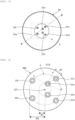
- Fig. 3 is a view illustrating the valve seat plate 36 that is seen from the center axis CF1 of the fuel injector 30 (an arrow A direction in Fig. 2 ).
- Fig. 4 is an enlarged view of inside of a frame C in Fig. 3 .
- Fig. 5 is a cross-sectional view of the tip portion of the fuel injector 30 that is taken along line B-B as the shortest line connecting a center of the first injection port 31a and a center of the second injection port 31c, which will be described below, in Fig. 4 .
- the plural injection ports 31a to 31f are perforated, and the injection ports 31a to 31f include the first injection port 31a and the second injection port 31c, which will be described below.
- the first injection port 31a is perforated such that a center of an opening of the injection port is located on a first circle with a first radius R1 from the center axis CF1 of the fuel injector 30.
- the second injection port 31c is perforated such that a center of an opening of the injection port 31c is located on a second circle with a larger second radius R2 than the first radius R1 from the center axis CF1 of the fuel injector 30 and is located on an opposite side of a tangent F-F of the first circle, which passes the center of the opening of the first injection port 31a, from the center axis CF1 of the fuel injector 30 (on a shorter arc ⁇ of arcs of the second circle passing points where the tangent F-F intersects the second circle).
- the injection port 31c is perforated such that the center of the opening of the injection port 31c is located at a position on the second circle, the position being located at approximately 30° from a perpendicular line D-D to the tangent F-F, which passes the injection port 31a.
- the injection port 31b is perforated such that a center of an opening thereof is located at a specified position on the first circle, and the injection ports 31d to 31f are perforated such that a center of an opening of each thereof is located at a specified position on the second circle.
- a positional relationship between the injection port 31b and the injection port 31d is similar to a positional relationship between the injection port 31a and the injection port 31c.
- the injection port 31d is perforated such that a center of an opening of the injection port 31d is located on the second circle with the second radius R2 from the center axis CF1 of the fuel injector 30 and is located on an opposite side of a tangent of the first circle, which passes the center of the opening of the injection port 31b, from the center axis CF1 of the fuel injector 30.
- an angle of a projection angle that is projected to the cross section that is, a projection angle defined by a center axis CF2 of the first injection port 31a and the center axis CF1 of the fuel injector 30 is set as a first angle ⁇ 1.
- An angle of a projection angle that is projected to the cross section similarly and that is defined by a center axis CF3 of the second injection port 31c and the center axis CF1 of the fuel injector 30 is set as a second angle ⁇ 2.
- the first injection port 31a and the second injection port 31c are perforated such that the first angle ⁇ 1 becomes larger than the second angle ⁇ 2.
- the first angle ⁇ 1 is each angle on an acute angle side of the projection angles defined by the center axis CF2 of the first injection port 31a and the center axis CF1 of the fuel injector 30.
- the second angle ⁇ 2 is each angle on an acute angle side of the projection angles defined by the center axis CF3 of the second injection port 31c and the center axis CF1 of the fuel injector 30.
- the first injection port 31a and the second injection port 31c are each perforated such that, in regard to edges 32a to 32d of the openings on an injection upstream side (an inner circumferential surface side of the valve seat plate 36) of the first injection port 31a and the second injection port 31c, the edge 32a (the edge 32a on the center axis CF1 side of the fuel injector 30 in regard to the tangent of the first circle passing the center of the first injection port 31a) of the first injection port 31a and the edge 32d (the edge 32d on an opposite side from the center axis CF1 of the fuel injector 30 in regard to the tangent of the second circle passing the center of the second injection port 31c) of the second injection port 31c on sides not opposing each other have obtuse angles and that the edge 32b (the edge 32b on an opposite side of the center axis CF1 side of the fuel injector 30 in regard to the tangent of the first circle passing the center of the first injection port 31a) of the first injection port
- the injection ports 31a to 31f are each formed with a guide area L, which is formed on the upstream side (on the inner side of the valve seat plate 36) and has a small diameter, and a diffusion area M, which is formed on a downstream side (the combustion chamber 21 side) and is formed by counter-boring to have a larger diameter than the guide area L.
- a bottom surface of the diffusion area M is formed in a step shape that is orthogonal to a center axis of the guide area L, for example.
- the fuel that is injected from the guide area L into the combustion chamber 21 via the diffusion area M is diffused as the spray.
- each of the center axis CF2 of the first injection port 31a and the center axis CF3 of the second injection port 31c described above corresponds to the center axis of the guide area L in the each injection port.
- the tip section of the fuel injector is designed to be thin, and the ratio ⁇ of the diameter d of the injection port to the depth 1 of the guide area L in the injection port of the fuel injector tends to be low.
- the ratio ⁇ is approximately 1 to 3 for the fuel injector in the gasoline engine, and the ratio ⁇ is approximately 5 to 10 for the fuel injector in the diesel engine.
- the guide area in the injection port of the fuel injector in the gasoline engine is shorter than that of the fuel injector in the diesel engine, and the fuel flow tends to be separated from an inner wall surface of the injection port of the fuel injector in the gasoline engine when compared to that of the fuel injector in the diesel engine.
- the fuel injector 30 includes the plural injection ports 31a to 31f, each of which injects the fuel into the internal combustion engine 10, and the injection ports 31a to 31f are provided in plural on the first circle with the first radius R1 and on the second circle with the larger second radius R2 than the first radius R1.
- the plural injection ports 31a to 31f include the first injection port 31a and the second injection port 31c.
- the center of the opening of the first injection port 31a is provided on the first circle.
- the center of the opening of the second injection port 31c is provided on the second circle on the opposite side of the tangent F-F of the first circle, which passes the center of the opening of the first injection port 31a, from the center axis CF1 of the fuel injector 30.
- the first circle provided with the first injection port 31a and the second circle provided with the second injection port 31c are concentric circles, a center of each of which is set on the center axis CF1 of the fuel injector 30.
- the fuel injector 30 is configured that, when seen in the cross section on the line B-B as the shortest line connecting the center of the first injection port 31a and the center of the second injection port 31c, the first angle ⁇ 1, which is defined by the center axis CF2 of the first injection port 31a and the center axis CF1 of the fuel injector 30, is larger than the second angle ⁇ 2, which is defined by the center axis CF3 of the second injection port 31c and the center axis CF1 of the fuel injector 30.
- the first injection port 31a and the second injection port 31c are configured that the edge on the injection upstream side of the first injection port 31a and the edge on the injection upstream side of the second injection port 31c on the sides not opposing each other have the obtuse angles and that the edge on the injection upstream side of the first injection port 31a and the edge on the injection upstream side of the second injection port 31c on the sides opposing each other have the acute angles.
- the edge on the injection upstream side of the first injection port 31a and the edge on the injection upstream side of the second injection port 31c on the sides opposing each other have the acute angles
- the second injection port is provided on the second circle on the opposite side of the tangent F-F of the first circle, which passes the center of the opening of the first injection port 31a, from the center axis CF1 of the fuel injector.
- the number of the injection ports perforated in the fuel injector 30, the arrangement and size of an aperture of each of the injection ports, the angle defined by the axis of the injection port and the center axis CF1 of the fuel injector 30, the shape of the counterbore, and the like can be designed according to design of the internal combustion engine 10, to which the fuel injector 30 is attached.
- the injection port 31c is configured to be perforated such that the center of the opening of the injection port 31c is located at the position on the second circle and that the position is located at the angle of approximately 30° from the perpendicular line D-D to the tangent F-F, which passes the first injection port 31a.
- the second injection port 31c may be at least configured to be located on the arc of the second circle on the opposite side of the tangent F-F from the center axis CF1 of the fuel injector 30, that is, may be perforated such that the center of the opening of the injection port 31c is located on the second circle within a range of ⁇ 90° from the perpendicular line D-D to the tangent F-F, which passes the first injection port 31a.
- the second injection port 31c can have the greater influence on the fuel flow into the first injection port 31a as being located on the arc of the second circle that is closer to the perpendicular line D-D, and it is preferably configured that the center of the opening of the injection port 31c is located on the arc of the second circle within a range of ⁇ 45° from the perpendicular line D-D to the tangent F-F, which passes the first injection port 31a.
- the fuel flow is more likely to be separated from the inner wall surface of the injection port than another portion.
- the fuel flow is more likely to be separated from the inner wall surface of the injection port.
- the fuel injector 30 in this embodiment is the fuel injector 30 that injects the fuel into the internal combustion engine 10 from the plural injection ports 31a to 31f, and is provided with the plural injection ports 31a to 31f on the first circle with the first radius R1 and on the second circle with the larger second radius R2 than the first radius R1.
- the ratio ⁇ of the diameter d of each of the injection ports 31a to 31f to the depth 1 of the guide area L formed in each injection port is approximately 1, and the fuel flow through each of the injection ports is less likely to be rectified before being injected from the outlet on the downstream side.
- the plural injection ports 31a to 31f include: the first injection port 31a, the center of the opening of which is provided on the first circle; and the second injection port 31c, the center of the opening of which is provided on the second circle on the opposite side of the tangent of the first circle, which passes the center of the opening of the first injection port 31a, from the center axis CF1 of the fuel injection 30.
- first injection port 31a and the second injection port 31c are configured that, when seen in the cross section on the line B-B as the shortest line connecting the center of the first injection port 31a and the center of the second injection port 31c, the first angle ⁇ 1, which is defined by the center axis CF2 of the first injection port 31a and the center axis CF1 of the fuel injector 30, is larger than the second angle ⁇ 2, which is defined by the center axis CF3 of the second injection port 31c and the center axis CF1 of the fuel injector 30.
- the first injection port 31a and the second injection port 31c can be configured that, when seen in the cross section on the shortest line connecting the center of the first injection port 31a and the center of the second injection port 31c, of the edges on the injection upstream side of the first injection port 31a, at least the edge 32a on the side not opposing the edge 32d on the injection upstream side of the second injection port 31c can have the obtuse angle, and in regard to the first injection port 31a, a flux of the fuel flowing into the first injection port 31a from the edge 32a on the side not opposing the second injection port 31c can be less likely to be separated from the inner wall surface of the first injection port.
- the second injection port 31c is provided on the second circle on the opposite side of the tangent F-F of the first circle from the center axis CF1 of the fuel injector 30, it is possible to cause the fuel present between the first injection port 31a and the second injection port 31c to flow into each of the injection ports 31a, 31c, so as to reduce the flow rate of the fuel that flows into the first injection port 31a from the edge 32b on the side opposing the second injection port 31c among the edges on the injection upstream side of the first injection port 31a.
- the flux of the fuel flowing into the first injection port 31a from the edge 32b on the side opposing the second injection port 31c can be less likely to be separated from the inner wall surface of the first injection port.
- the first injection port 31a it is possible to favorably balance the fuel flow from the side not opposing the second injection port 31c and the fuel flow from the side opposing the second injection port 31c by exerting the influence of the fuel flow by the second injection port 31c on the fuel flow by the first injection port 31a.
- the first injection port 31a and the second injection port 31c can be configured that the edge 32a on the injection upstream side of the first injection port 31a and the edge 32d on the injection upstream side of the second injection port 31c on the sides not opposing each other can have the obtuse angles, and in regard to the first injection port 31a and the second injection port 31c, the flux of the fuel flowing into each of the injection ports 31a, 31c from respective one of the edges 32a, 32d on the sides not opposing each other can be less likely to be separated from the inner wall surface of each injection port.
- the second injection port is provided on the second circle on the opposite side of the tangent F-F of the first circle, which passes the center of the opening of the first injection port 31a, from the center axis CF1 of the fuel injector, it is possible to cause the fuel present between the first injection port 31a and the second injection port 31c to flow into each of the injection ports 31a, 31c, so as to reduce the flow rate of the fuel that flows into each of the injection ports from respective one of the edges 32b, 32c on the injection upstream side of the injection ports.
- the flux of the fuel flowing into each of the injection ports 31a, 31c from respective one of the edges 32b, 32c on the sides opposing each other can be less likely to be separated from the inner wall surface of each injection port.
- the first injection port 31a and the second injection port 31c it is possible to favorably balance the fuel flows from the sides not opposing each other and the fuel flows from the sides opposing each other by the mutual interaction between the influence of the first injection port 31a on the fuel flow and the influence of the second injection port 31c on the fuel flow. As a result, it is possible to suppress the separation of the fuel flow in the injection port of each of the first injection port 31a and the second injection port 31c.
- the fuel injector 30 in this embodiment is the fuel injector 30 that injects the fuel into the internal combustion engine 10 from the plural injection ports 31a to 31f, and is configured that the plural injection ports 31a to 31f are provided in plural on the first circle with the first radius R1 and on the second circle with the larger second radius R2 than the first radius R1 and include: the first injection port 31a, the center of the opening of which is provided on the first circle; and the second injection port 31c, the center of the opening of which is provided on the second circle on the opposite side of the tangent of the first circle, which passes the center of the opening of the first injection port 31a, from the center axis CF1 of the fuel injection 30, and that, when seen in the cross section on the shortest line connecting the center of the first injection port 31a and the center of the second injection port 31c, of the edges on the upstream side of the first injection port 31a, at least the edge 32a on the side not opposing the second injection port 31c has the obtuse angle.
- the flux of the fuel flowing into the first injection port 31a from the edge 32a on the side not opposing the second injection port 31c can be less likely to be separated from the inner wall surface of the first injection port.
- the second injection port 31c is provided on the second circle on the opposite side of the tangent line F-F of the first circle from the center axis CF1 of the fuel injector 30, it is possible to cause the fuel present between the first injection port 31a and the second injection port 31c to flow into each of the injection ports 31a, 31c, so as to reduce the flow rate of the fuel flowing into the first injection port 31a from the edge 32b on the side opposing the second injection port 31c among the edges on the injection upstream side of the first injection port 31a.
- the flux of the fuel flowing into the first injection port 31a from the edge 32b on the side opposing the second injection port 31c can be less likely to be separated from the inner wall surface of the first injection port 31a.
- the first injection port 31a it is possible to favorably balance the fuel flow from the side not opposing the second injection port 31c and the fuel flow flowing from the side opposing the second injection port 31c by exerting the influence of the fuel flow by the second injection port 31c on the fuel flow by the first injection port 31a.
- the fuel injector 30 in this embodiment is the fuel injector 30 that injects the fuel into the internal combustion engine 10 from the plural injection ports 31a to 31f, and is configured that the plural injection ports 31a to 31f are provided in plural on the first circle with the first radius R1 and on the second circle with the larger second radius R2 than the first radius R1 and include: the first injection port 31a, the center of the opening of which is provided on the first circle; and the second injection port 31c, the center of the opening of which is provided on the second circle on the opposite side of the tangent of the first circle, which passes the center of the opening of the first injection port 31a, from the center axis CF1 of the fuel injection 30, and that, when seen in the cross section on the shortest line connecting the center of the first injection port 31a and the center of the second injection port 31c, the edge 32a on the injection upstream side of the first injection port 31a and the edge 32d on the injection upstream side of the second injection port 31c on the sides not opposing each other have the obtuse
- the flux of the fuel flowing into each of the injection ports 31a, 31c from respective one of the edges 32a, 32d on the sides not opposing each other can be less likely to be separated from the inner wall surface of each injection port.
- the second injection port 31c is provided on the second circle on the opposite side of the tangent F-F of the first circle from the center axis CF1 of the fuel injector 30, it is possible to cause the fuel present between the first injection port 31a and the second injection port 31c to flow into each of the fuel injection ports 31a, 31c, so as to reduce the flow rate of the fuel flowing into each of the injection ports from respective one of the edges 32a, 32d on the injection upstream sides of the injection ports.
- the flux of the fuel flowing into each of the injection ports 31a, 31c from respective one of the edges 32b, 32c on the sides opposing each other can be less likely to be separated from the inner wall surface of each injection port.
- the first injection port 31a and the second injection port 31c it is possible to favorably balance the fuel flows from the sides not opposing each other and the fuel flows from the sides opposing each other by the mutual interaction between the influence of the first injection port 31a on the fuel flow and the influence of the second injection port 31c on the fuel flow. As a result, it is possible to suppress the separation of the fuel flow in the injection port of each of the first injection port 31a and the second injection port 31c.
- the fuel injector 30 is configured that the ratio ⁇ of the diameter d of each of the first injection port 31a and the second injection port 31c to the length 1 of each injection port is equal to or lower than 3. In such a configuration, the fuel flow through the injection port is less likely to be rectified from the turbulent flow state before being injected from the outlet on the downstream side, and the fuel flow tends to be separated from the inner wall surface of the injection port.
- the second injection port 31c is provided on the second circle on the opposite side of the tangent F-F of the first circle, which passes the center of the opening of the first injection port 31a, from the center axis CF1 of the fuel injector, and it is configured that the first angle ⁇ 1, which is defined by the center axis CF2 of the first injection port 31a and the center axis CF1 of the fuel injector 30, is larger than the second angle ⁇ 2, which is defined by the center axis CF3 of the second injection port 31c and the center axis CF1 of the fuel injector 30.
- the first angle ⁇ 1 which is defined by the center axis CF2 of the first injection port 31a and the center axis CF1 of the fuel injector 30.
- the fuel injector 30 is configured that the ratio ⁇ of the diameter d of each of the first injection port 31a and the second injection port 31c to the length 1 of each injection port is equal to or lower than 3. In such a configuration, the fuel flow through the injection port is less likely to be rectified from the turbulent flow state before being injected from the outlet on the downstream side, and the fuel flow tends to be separated from the inner wall surface of the injection port.
- the second injection port 31c is provided on the second circle on the opposite side of the tangent F-F of the first circle, which passes the center of the opening of the first injection port 31a, from the center axis CF1 of the fuel injector, and it is configured that the edge 32a on the injection upstream side of the first injection port 31a and the edge 32d on the injection upstream side of the second injection port 31c on the sides not opposing each other have the obtuse angles.
- the length 1 of the injection port is only the length of the guide area L and does not include the length of the diffusion area M.
- the internal combustion engine 10 is configured to include the above-described fuel injector 30. According to such a configuration, since the internal combustion engine 10 includes the above-described fuel injector 30, it is possible to suppress the separation of the fuel flow in each of the first injection port 31a and the second injection port 31c during the fuel injection, and it is possible to reduce the adhesion of the fuel to the tip of the fuel injector 30 and the like, which is a cause of a deposit produced by the incomplete combustion.
- the first injection port 31a and the second injection port 31c are configured that the ratio ⁇ of the diameter d of each of the injection ports 31a, 31c to the depth 1 of the guide area L formed in each injection port is approximately 1.
- the ratio ⁇ of the diameter d of each of the injection ports to the depth 1 of the guide area L in each injection port is not limited to 1. Similar effects to those in this embodiment can be exerted with a configuration in which the ratio ⁇ is lower than 1 and a configuration in which the ratio ⁇ exceeds 1.
Landscapes
- Engineering & Computer Science (AREA)
- Chemical & Material Sciences (AREA)
- Combustion & Propulsion (AREA)
- Mechanical Engineering (AREA)
- General Engineering & Computer Science (AREA)
- Fuel-Injection Apparatus (AREA)
Description
- The present invention relates to a fuel injector that injects fuel into an internal combustion engine and to an internal combustion engine including the fuel injector.
- As a conventional fuel injector, a fuel injector is configured to be provided with plural injection ports for injecting fuel in a tip portion of the fuel injector, to shut off injection of the fuel from the injection ports into a combustion chamber of the internal combustion engine when a valve body and a valve seat surface provided on the inside of the fuel injector abut each other, and to inject the fuel from the injection ports into the combustion chamber when the valve body and the valve seat surface separate from each other (for example, see PTL 1).
-
PTL 2 describes that a fuel injection valve has a nozzle section with a first imaginary circle which is defined approximately coaxially to a center axis of the nozzle section, and has a first arc with injection orifices and a first arc without injection orifices. - PTL 3 describes a nozzle assembly for a fuel injector for injecting fuel into a combustion chamber of an internal combustion engine.
-
- PTL 1:
JP-A-2014-1660 - PTL 2:
DE 10 2006 000243 A1 - PTL 3:
EP 3 173 614 A1 - In the fuel injectors disclosed in
PTL 1 and the like, a fuel flow is separated from a side surface (an inner wall surface) of the injection port at the time when the fuel is injected from the injection port. Consequently, some of the fuel injected from the injection port possibly spatters around the injection port, produces droplets, and adheres to an outer circumferential wall surface at a tip of the fuel injector. When the fuel produces the droplets and adheres to the tip of the fuel injector, incomplete combustion occurs, which is a cause of generation of unburned particle matters. - The present invention has been made with the above-described problem as the background and therefore has a purpose of providing a fuel injector capable of reducing separation of a fuel flow in an injection port during fuel injection.
- The invention is set out in the appended set of claims.
- The fuel injector according to the present invention is the fuel injector (30) that injects fuel into the internal combustion engine (10) from the plural injection ports (31a to 31f). In the fuel injector (30), it is configured that the plural injection ports (31a to 31f) are provided in plural on the first circle with the first radius (R1) and on the second circle with the larger second diameter (R2) than the first radius (R1), and include: the first injection port (31a), a center of an opening of which is provided on the first circle; and the second injection port (31c), a center of an opening of which is provided on the second circle on an opposite side of a tangent of the first circle passing the center of the opening of the first injection port (31a) from a center axis of the fuel injection (30), that, when seen in a cross section on the shortest line connecting the center of the first injection port (31a) and the center of the second injection port (31c), of edges on an injection upstream side of the first injection port (31a), at least the edge (32a) on a side not opposing the edge (32d) on an injection upstream side of the second injection port (31c) has an obtuse angle.
- With such a configuration, it is configured that, of the plural injection ports (31a to 31f), when the first injection port (31a), the center of the opening of which is provided on the first circle, and the second injection port (31c), the center of the opening of which is provided on the second circle on the opposite side of the tangent (F-F) of the first circle, which passes the center of the opening of the first injection port (31a), from the center axis (CF1) of the fuel injection (30) are seen in the cross section on the shortest line connecting the center of the first injection port (31a) and the center of the second injection port (31c), of the edges on the injection upstream side of the first injection port (31a), at least the edge (32a) on the side not opposing the edge on the injection upstream side of the second injection port (31c) has the obtuse angle. Thus, in regard to the first injection port (31a), the flux of the fuel flowing into the first injection port (31a) from the edge (32a) on the side not opposing each other can be less likely to be separated from the inner wall surface of the first injection port. In addition, since it is configured that the second injection port (31c) is provided on the second circle on the opposite side of the tangent (F-F) of the first circle from the center axis (CF1) of the fuel injector (30), it is possible to reduce a flow rate of the fuel that flows into the first injection port from the edge (32b) on the injection upstream side of the first injection port by causing the fuel present between the first injection port (31a) and the second injection port (31c) to flow into each of the injection ports (31a, 31c), and, in regard to the first injection port (31a), a flux of the fuel flowing into the first injection port (31a) from the edge (32b) on a side opposing the second injection port (31c) can be less likely to be separated from the inner wall surface of the first injection port. In this way, it is possible to favorably balance the fuel flow into the first injection port (31a) from the side not opposing the second injection port (32c) and the fuel flow thereinto from the side opposing the second injection port (32c) by exerting the fuel flow by the second injection port (31c) to the fuel flow by the first injection port (31a), so as to suppress the separation of the fuel flow in the injection port of the first injection port (31a).
- The internal combustion engine (10) according to the present invention is configured to include the above-described fuel injector (30). According to such a configuration, since the internal combustion engine (10) includes the above-described fuel injector (30), it is possible to suppress the separation of the fuel flow in the first injection port (31a) at least during fuel injection, and it is possible to reduce adhesion of the fuel to a tip of the fuel injector (30) and the like, which is a cause of a deposit produced by incomplete combustion.
- The present invention may only have the matters used to define the invention and described in the claims of the present invention, or may have a configuration other than the matters used to define the invention in addition to the matters used to define the invention and described in the claims of the present invention.
-
-
Fig. 1 is a view for explaining an internal combustion engine that includes a fuel injector according to an embodiment. -
Fig. 2 is a side view of the fuel injector. -
Fig. 3 is a view for explaining fuel injection ports provided to the fuel injector. -
Fig. 4 is an enlarged view of inside of a frame C inFig. 3 . -
Fig. 5 is a cross-sectional view that is taken along line B-B inFig. 3 . - A description will hereinafter be made on an exemplary embodiment of a fuel injector and an internal combustion engine including the fuel injector according to the present invention with reference to the drawings. A configuration, operation, and the like of the embodiment, which will be described below, constitute merely one example, and the present invention is not limited to a case with such a configuration, such operation, and the like. The same or similar description will appropriately be simplified or will not be made below. In the drawings, the same or similar members or portions will not be denoted by a reference sign or will be denoted by the same reference sign. A detailed structure will appropriately be illustrated in a simplified manner or will not be illustrated.
- The fuel injector according to this embodiment can be applied as a fuel injector that injects fuel in an internal combustion engine (for example, a gasoline engine, a diesel engine, or the like). The internal combustion engine including the fuel injector according to the present invention, for example, an internal combustion engine that uses gasoline as the fuel can be applied as an internal combustion engine for a vehicle, a power generator, or the like. In this embodiment, a description will be made on an example in which the gasoline internal combustion engine for a vehicle is used as the internal combustion engine. However, the present invention is not particularly limited thereto.
- A description will be made on a configuration of an
internal combustion engine 10 according to this embodiment with reference toFig. 1 . As illustrated inFig. 1 , theinternal combustion engine 10 includes: anengine body 20 that forms acombustion chamber 21; afuel injector 30 that injects fuel into thecombustion chamber 21; anignition plug 40 that generates spark discharge in thecombustion chamber 21; anintake valve 50 that connects/disconnects thecombustion chamber 21 to/from anintake passage 24; anexhaust valve 60 that connects/disconnects thecombustion chamber 21 to/from anexhaust passage 25; apiston 70 that operates linearly in conjunction with combustion of air-fuel mixture, which contains the fuel and air, in thecombustion chamber 21; a connectingrod 80 and a crankshaft (not illustrated) that convert the linear operation of thepiston 70 into rotational motion; a fuel supplier (not illustrated) that supplies the fuel from a fuel tank (not illustrated), which stores the fuel, to thefuel injector 30; and the like. - The
engine body 20 includes a cylinder head 22 and acylinder block 23, and the cylinder head 22 and thecylinder block 23 form thecombustion chamber 21. In the cylinder head 22, afirst attachment hole 26 is formed near a joint section between the cylinder head 22 and theintake passage 24, and communicates with thecombustion chamber 21 from outside of the cylinder head 22. Thefuel injector 30 is inserted in thefirst attachment hole 26. In addition, in the cylinder head 22, asecond attachment hole 27 is formed between an attachment position of theintake valve 50 and an attachment position of theexhaust valve 60, and communicates with thecombustion chamber 21 from the outside of the cylinder head 22. Theignition plug 40 is inserted in thesecond attachment hole 27. - The
fuel injector 30 is inserted in thefirst attachment hole 26 such that avalve seat plate 36, which is provided withplural injection ports 31a to 31f injecting the fuel, faces thecombustion chamber 21, and directly injects the fuel into thecombustion chamber 21. Aseal section 38 is provided to an outer circumference of a tip portion of thefuel injector 30, and is configured to close a clearance between thefuel injector 30 and thefirst attachment hole 26 so as to seal burned gas from thecombustion chamber 21. - The tip of the
fuel injector 30 is configured to face the inside of thecombustion chamber 21 when thefuel injector 30 is inserted in thefirst attachment hole 26. In this way, thefuel injector 30 can directly inject a fuel spray into thecombustion chamber 21. - In this embodiment, in the cylinder head 22, the
first attachment hole 26 is configured to be provided near the joint section between the cylinder head 22 and theintake passage 24. However, in the cylinder head 22, thefirst attachment hole 26 may be configured to be provided between the attachment position of theintake valve 50 and the attachment position of theexhaust valve 60. Even in such a configuration, the tip of thefuel injector 30 is configured to face the inside of thecombustion chamber 21 when thefuel injector 30 is inserted in thefirst attachment hole 26, and thefuel injector 30 can directly inject the fuel spray into thecombustion chamber 21. - In addition, the
fuel injector 30 is configured to be arranged such that the tip thereof faces thecombustion chamber 21. However, thefuel injector 30 may be configured to be arranged such that the tip thereof faces theintake passage 24. - A description will be made on the
fuel injector 30 according to this embodiment with reference toFig. 1 to Fig. 5 . As illustrated inFig. 1 , thefuel injector 30 is attached near the joint section between the cylinder head 22 and theintake passage 24 such that a center axis CF1 of thefuel injector 30 is oriented slightly downward (oriented to thepiston 70 side) in thecombustion chamber 21 and that theinjection ports 31a to 31f, each of which is provided to the tip portion of thefuel injector 30, faces the inside of thecombustion chamber 21. - As illustrated in
Fig. 2 , thefuel injector 30 includes: thevalve seat plate 36 that is formed with theplural injection ports 31a to 31f and is also formed with avalve seat section 36a; avalve body 35 that can block a fuel supply to theinjection ports 31a to 31f when abutting thevalve seat section 36a; asolenoid coil 33 that can cause thevalve body 35 to move between a position where thevalve body 35 abuts thevalve seat section 36a and a position where thevalve body 35 does not abut thevalve seat section 36a; aspring 34 that urges thevalve body 35; and the like. - An inner side of the
valve seat plate 36 is formed in a dome shape that corresponds to a ball shape of a tip section 35a of thevalve body 35. On the inner side of thevalve seat plate 36, thevalve seat section 36a is formed in a portion that the tip section 35a of thevalve body 35 abuts, and forms a seal when the tip section 35a and thevalve seat section 36a contact each other. In addition, on an inner side of thevalve seat section 36a (the center axis CF1 side of the fuel injector 30) in thevalve seat plate 36, theplural injection ports 31a to 31f, each of which communicates between the inside and the outside of thevalve seat plate 36, are formed. - The
fuel injector 30 is an electromagnetic valve of a Normal Close (NC) type that is brought into a closed state where the fuel is not injected from theinjection ports 31a to 31f in a non-energized state where a specified voltage is not applied to thesolenoid coil 33. When thesolenoid coil 33 is in the non-energized state, the ball-shaped tip section 35a of thevalve body 35, which is urged by thespring 34, tightly contacts thevalve seat section 36a of thevalve seat plate 36. As a result, thefuel injector 30 is brought into the closed state where the fuel supplied from afuel supply port 37 does not leak from theinjection ports 31a to 31f. On the contrary, in an energized state where the specified voltage is applied to thesolenoid coil 33, thevalve body 35 moves to a position away from thevalve seat section 36a of thevalve seat plate 36, and a clearance is produced between thevalve body 35 and thevalve seat section 36a. In this way, thefuel injector 30 is brought into an open state where the fuel supplied from thefuel supply port 37 flows through the clearance between the valve body 42 and thevalve seat section 36a and is injected in the spray form from theinjection ports 31a to 31f. - In this embodiment, the
fuel injector 30 is configured to be switched between the open state and the closed state by the solenoid coil. However, thefuel injector 30 may be configured to be switched between the open state and the closed state by a piezoelectric element or the like, for example. - The fuel that is supplied from the
fuel supply port 37 into thefuel injector 30 flows through a channel (not illustrated) provided in thefuel injector 30, and reaches thevalve seat section 36a of thevalve seat plate 36. In the open state of thefuel injector 30, after reaching thevalve seat section 36a, the fuel flows through a constricted portion between the tip section 35a of thevalve body 35 and thevalve seat section 36a, then flows in a direction of the center axis CF1 of thefuel injector 30, and reaches theinjection ports 31a to 31f. Then, the fuel flows through theinjection ports 31a to 31f and is injected into the combustion chamber 21 (seeFig. 5 ). On the contrary, in the closed state of thefuel injector 30, the constricted portion between the tip section 35a of thevalve body 35 and thevalve seat section 36a is closed, and thus the fuel injection into thecombustion chamber 21 is blocked. - A description will be made on the
injection ports 31a to 31f of thefuel injector 30 according to this embodiment with reference toFig. 3 to Fig. 5 .Fig. 3 is a view illustrating thevalve seat plate 36 that is seen from the center axis CF1 of the fuel injector 30 (an arrow A direction inFig. 2 ).Fig. 4 is an enlarged view of inside of a frame C inFig. 3 .Fig. 5 is a cross-sectional view of the tip portion of thefuel injector 30 that is taken along line B-B as the shortest line connecting a center of thefirst injection port 31a and a center of thesecond injection port 31c, which will be described below, inFig. 4 . - As illustrated in
Fig. 3 and Fig. 4 , in thevalve seat plate 36 of thefuel injector 30, theplural injection ports 31a to 31f, each of which communicates between the inside and the outside of thevalve seat plate 36, are perforated, and theinjection ports 31a to 31f include thefirst injection port 31a and thesecond injection port 31c, which will be described below. Thefirst injection port 31a is perforated such that a center of an opening of the injection port is located on a first circle with a first radius R1 from the center axis CF1 of thefuel injector 30. Thesecond injection port 31c is perforated such that a center of an opening of theinjection port 31c is located on a second circle with a larger second radius R2 than the first radius R1 from the center axis CF1 of thefuel injector 30 and is located on an opposite side of a tangent F-F of the first circle, which passes the center of the opening of thefirst injection port 31a, from the center axis CF1 of the fuel injector 30 (on a shorter arc α of arcs of the second circle passing points where the tangent F-F intersects the second circle). In addition, theinjection port 31c is perforated such that the center of the opening of theinjection port 31c is located at a position on the second circle, the position being located at approximately 30° from a perpendicular line D-D to the tangent F-F, which passes theinjection port 31a. - The
injection port 31b is perforated such that a center of an opening thereof is located at a specified position on the first circle, and theinjection ports 31d to 31f are perforated such that a center of an opening of each thereof is located at a specified position on the second circle. Here, a positional relationship between theinjection port 31b and theinjection port 31d is similar to a positional relationship between theinjection port 31a and theinjection port 31c. Theinjection port 31d is perforated such that a center of an opening of theinjection port 31d is located on the second circle with the second radius R2 from the center axis CF1 of thefuel injector 30 and is located on an opposite side of a tangent of the first circle, which passes the center of the opening of theinjection port 31b, from the center axis CF1 of thefuel injector 30. - As illustrated in
Fig. 5 , when seen in a cross section on a plane that includes line B-B as the shortest line connecting the center of thefirst injection port 31a and the center of thesecond injection port 31c and that is parallel to the center axis CF1 of thefuel injector 30, an angle of a projection angle that is projected to the cross section, that is, a projection angle defined by a center axis CF2 of thefirst injection port 31a and the center axis CF1 of thefuel injector 30 is set as a first angle Θ1. An angle of a projection angle that is projected to the cross section similarly and that is defined by a center axis CF3 of thesecond injection port 31c and the center axis CF1 of thefuel injector 30 is set as a second angle Θ2. In this case, thefirst injection port 31a and thesecond injection port 31c are perforated such that the first angle Θ1 becomes larger than the second angle Θ2. - Here, as illustrated in
Fig. 5 , the first angle Θ1 is each angle on an acute angle side of the projection angles defined by the center axis CF2 of thefirst injection port 31a and the center axis CF1 of thefuel injector 30. The second angle Θ2 is each angle on an acute angle side of the projection angles defined by the center axis CF3 of thesecond injection port 31c and the center axis CF1 of thefuel injector 30. - The first injection port 31a and the second injection port 31c are each perforated such that, in regard to edges 32a to 32d of the openings on an injection upstream side (an inner circumferential surface side of the valve seat plate 36) of the first injection port 31a and the second injection port 31c, the edge 32a (the edge 32a on the center axis CF1 side of the fuel injector 30 in regard to the tangent of the first circle passing the center of the first injection port 31a) of the first injection port 31a and the edge 32d (the edge 32d on an opposite side from the center axis CF1 of the fuel injector 30 in regard to the tangent of the second circle passing the center of the second injection port 31c) of the second injection port 31c on sides not opposing each other have obtuse angles and that the edge 32b (the edge 32b on an opposite side of the center axis CF1 side of the fuel injector 30 in regard to the tangent of the first circle passing the center of the first injection port 31a) of the first injection port 31a and the edge 32c (the edge 32c on the center axis CF1 side of the fuel injector 30 in regard to the tangent of the second circle passing the center of the first injection port 31a) of the second injection port 31c on sides opposing each other have acute angles.
- The
injection ports 31a to 31f are each formed with a guide area L, which is formed on the upstream side (on the inner side of the valve seat plate 36) and has a small diameter, and a diffusion area M, which is formed on a downstream side (thecombustion chamber 21 side) and is formed by counter-boring to have a larger diameter than the guide area L. A bottom surface of the diffusion area M is formed in a step shape that is orthogonal to a center axis of the guide area L, for example. The fuel that is injected from the guide area L into thecombustion chamber 21 via the diffusion area M is diffused as the spray. Here, each of the center axis CF2 of thefirst injection port 31a and the center axis CF3 of thesecond injection port 31c described above corresponds to the center axis of the guide area L in the each injection port. A ratio ε (ε = 1/d) of a diameter d of each of theinjection ports 31a to 31f to adepth 1 of the guide area L of each injection port is approximately 1. Compared to a case where thefuel injector 30 is applied to an internal combustion engine with a relatively high fuel injection pressure (for example, the diesel engine), when thefuel injector 30 is applied to an internal combustion engine with a relatively low fuel injection pressure (for example, the gasoline engine), the tip section of the fuel injector is designed to be thin, and the ratio ε of the diameter d of the injection port to thedepth 1 of the guide area L in the injection port of the fuel injector tends to be low. For example, the ratio ε is approximately 1 to 3 for the fuel injector in the gasoline engine, and the ratio ε is approximately 5 to 10 for the fuel injector in the diesel engine. The guide area in the injection port of the fuel injector in the gasoline engine is shorter than that of the fuel injector in the diesel engine, and the fuel flow tends to be separated from an inner wall surface of the injection port of the fuel injector in the gasoline engine when compared to that of the fuel injector in the diesel engine. - As described above, the
fuel injector 30 according to this embodiment includes theplural injection ports 31a to 31f, each of which injects the fuel into theinternal combustion engine 10, and theinjection ports 31a to 31f are provided in plural on the first circle with the first radius R1 and on the second circle with the larger second radius R2 than the first radius R1. - In the
fuel injector 30 according to this embodiment, theplural injection ports 31a to 31f include thefirst injection port 31a and thesecond injection port 31c. The center of the opening of thefirst injection port 31a is provided on the first circle. The center of the opening of thesecond injection port 31c is provided on the second circle on the opposite side of the tangent F-F of the first circle, which passes the center of the opening of thefirst injection port 31a, from the center axis CF1 of thefuel injector 30. In addition, the first circle provided with thefirst injection port 31a and the second circle provided with thesecond injection port 31c are concentric circles, a center of each of which is set on the center axis CF1 of thefuel injector 30. - In the
fuel injector 30 according to this embodiment, it is configured that, when seen in the cross section on the line B-B as the shortest line connecting the center of thefirst injection port 31a and the center of thesecond injection port 31c, the first angle Θ1, which is defined by the center axis CF2 of thefirst injection port 31a and the center axis CF1 of thefuel injector 30, is larger than the second angle Θ2, which is defined by the center axis CF3 of thesecond injection port 31c and the center axis CF1 of thefuel injector 30. - In the
fuel injector 30 according to this embodiment, thefirst injection port 31a and thesecond injection port 31c are configured that the edge on the injection upstream side of thefirst injection port 31a and the edge on the injection upstream side of thesecond injection port 31c on the sides not opposing each other have the obtuse angles and that the edge on the injection upstream side of thefirst injection port 31a and the edge on the injection upstream side of thesecond injection port 31c on the sides opposing each other have the acute angles. In addition, in regard to thefirst injection port 31a and thesecond injection port 31c, the edge on the injection upstream side of thefirst injection port 31a and the edge on the injection upstream side of thesecond injection port 31c on the sides opposing each other have the acute angles, and the second injection port is provided on the second circle on the opposite side of the tangent F-F of the first circle, which passes the center of the opening of thefirst injection port 31a, from the center axis CF1 of the fuel injector. - The number of the injection ports perforated in the
fuel injector 30, the arrangement and size of an aperture of each of the injection ports, the angle defined by the axis of the injection port and the center axis CF1 of thefuel injector 30, the shape of the counterbore, and the like can be designed according to design of theinternal combustion engine 10, to which thefuel injector 30 is attached. - In this embodiment, the
injection port 31c is configured to be perforated such that the center of the opening of theinjection port 31c is located at the position on the second circle and that the position is located at the angle of approximately 30° from the perpendicular line D-D to the tangent F-F, which passes thefirst injection port 31a. However, thesecond injection port 31c may be at least configured to be located on the arc of the second circle on the opposite side of the tangent F-F from the center axis CF1 of thefuel injector 30, that is, may be perforated such that the center of the opening of theinjection port 31c is located on the second circle within a range of ±90° from the perpendicular line D-D to the tangent F-F, which passes thefirst injection port 31a. In the configuration of theinjection port 31c perforated such that the center of the opening of theinjection port 31c is located on the second circle within the range of ±90° from the perpendicular line D-D to the tangent F-F, which passes thefirst injection port 31a, it is possible to suppress the separation of the fuel flow from the inner wall surface of each of the injection ports by a mutual interaction between an influence of thefirst injection port 31a on the fuel flow and an influence of thesecond injection port 31c on the fuel flow. Thesecond injection port 31c can have the greater influence on the fuel flow into thefirst injection port 31a as being located on the arc of the second circle that is closer to the perpendicular line D-D, and it is preferably configured that the center of the opening of theinjection port 31c is located on the arc of the second circle within a range of ±45° from the perpendicular line D-D to the tangent F-F, which passes thefirst injection port 31a. Compared to a configuration that the center of the opening of theinjection port 31c is located on the arc of the second circle within a range of ±45° to 90° from the perpendicular line D-D to the tangent F-F, which passes thefirst injection port 31a, in the configuration that the center of the opening of theinjection port 31c is located on the arc of the second circle within the range of ±45° from the perpendicular line D-D to the tangent F-F, which passes thefirst injection port 31a, it is possible to exhibit the further significant mutual interaction between the influence of thefirst injection port 31a on the fuel flow and the influence of thesecond injection port 31c on the fuel flow. - In general, near the edge on the injection upstream side of the injection port in the fuel injector, as a portion has the acuter edge angle, the fuel flow is more likely to be separated from the inner wall surface of the injection port than another portion. In addition, as a flow rate is increased, the fuel flow is more likely to be separated from the inner wall surface of the injection port. Furthermore, as the ratio ε (ε = 1/d) of the diameter d of the injection port to the
depth 1 of the guide area L formed in the injection port is reduced, that is, as the guide area L is shorter, the fuel flow through the injection port is less likely to be rectified from a turbulent flow state before being injected from an outlet on the downstream side, and the fuel flow tends to be separated from the inner wall surface of the injection port. In particular, in the case where the ratio ε falls below approximately 3, likeliness of the separation of the fuel flow tends to be significantly increased when compared to a case where the ratio exceeds 3. Then, when the fuel flow is separated, there is a possibility that disturbance occurs in a flow field and that the spray of the fuel injected from the injection port spatters around the injection port, produces droplets, and adheres to an outer circumferential wall surface at the tip of the fuel injector and the like. In theinternal combustion engine 10 in which the tip section of thefuel injector 30 is arranged to face the inside of thecombustion chamber 21, the fuel adheres to the tip of thefuel injector 30 and the like, and the adhered fuel is burned incompletely, which becomes a cause of producing unburned particle matters. - The
fuel injector 30 in this embodiment is thefuel injector 30 that injects the fuel into theinternal combustion engine 10 from theplural injection ports 31a to 31f, and is provided with theplural injection ports 31a to 31f on the first circle with the first radius R1 and on the second circle with the larger second radius R2 than the first radius R1. The ratio ε of the diameter d of each of theinjection ports 31a to 31f to thedepth 1 of the guide area L formed in each injection port is approximately 1, and the fuel flow through each of the injection ports is less likely to be rectified before being injected from the outlet on the downstream side. - To handle the above problem, in the
fuel injector 30, theplural injection ports 31a to 31f include: thefirst injection port 31a, the center of the opening of which is provided on the first circle; and thesecond injection port 31c, the center of the opening of which is provided on the second circle on the opposite side of the tangent of the first circle, which passes the center of the opening of thefirst injection port 31a, from the center axis CF1 of thefuel injection 30. In addition, thefirst injection port 31a and thesecond injection port 31c are configured that, when seen in the cross section on the line B-B as the shortest line connecting the center of thefirst injection port 31a and the center of thesecond injection port 31c, the first angle θ1, which is defined by the center axis CF2 of thefirst injection port 31a and the center axis CF1 of thefuel injector 30, is larger than the second angle Θ2, which is defined by the center axis CF3 of thesecond injection port 31c and the center axis CF1 of thefuel injector 30. - According to such a configuration, the
first injection port 31a and thesecond injection port 31c can be configured that, when seen in the cross section on the shortest line connecting the center of thefirst injection port 31a and the center of thesecond injection port 31c, of the edges on the injection upstream side of thefirst injection port 31a, at least theedge 32a on the side not opposing theedge 32d on the injection upstream side of thesecond injection port 31c can have the obtuse angle, and in regard to thefirst injection port 31a, a flux of the fuel flowing into thefirst injection port 31a from theedge 32a on the side not opposing thesecond injection port 31c can be less likely to be separated from the inner wall surface of the first injection port. In addition, since it is configured that thesecond injection port 31c is provided on the second circle on the opposite side of the tangent F-F of the first circle from the center axis CF1 of thefuel injector 30, it is possible to cause the fuel present between thefirst injection port 31a and thesecond injection port 31c to flow into each of theinjection ports first injection port 31a from theedge 32b on the side opposing thesecond injection port 31c among the edges on the injection upstream side of thefirst injection port 31a. In this way, in regard to thefirst injection port 31a, the flux of the fuel flowing into thefirst injection port 31a from theedge 32b on the side opposing thesecond injection port 31c can be less likely to be separated from the inner wall surface of the first injection port. From what have been described so far, in regard to thefirst injection port 31a, it is possible to favorably balance the fuel flow from the side not opposing thesecond injection port 31c and the fuel flow from the side opposing thesecond injection port 31c by exerting the influence of the fuel flow by thesecond injection port 31c on the fuel flow by thefirst injection port 31a. As a result, it is possible to suppress the separation of the fuel flow from the inner wall surface in the injection port of thefirst injection port 31a. - According to the configuration that the first angle Θ1 related to the
first injection port 31a is larger than the second angle Θ2 related to thesecond injection port 31c, thefirst injection port 31a and thesecond injection port 31c can be configured that theedge 32a on the injection upstream side of thefirst injection port 31a and theedge 32d on the injection upstream side of thesecond injection port 31c on the sides not opposing each other can have the obtuse angles, and in regard to thefirst injection port 31a and thesecond injection port 31c, the flux of the fuel flowing into each of theinjection ports edges first injection port 31a, from the center axis CF1 of the fuel injector, it is possible to cause the fuel present between thefirst injection port 31a and thesecond injection port 31c to flow into each of theinjection ports edges first injection port 31a and thesecond injection port 31c, the flux of the fuel flowing into each of theinjection ports edges first injection port 31a and thesecond injection port 31c, it is possible to favorably balance the fuel flows from the sides not opposing each other and the fuel flows from the sides opposing each other by the mutual interaction between the influence of thefirst injection port 31a on the fuel flow and the influence of thesecond injection port 31c on the fuel flow. As a result, it is possible to suppress the separation of the fuel flow in the injection port of each of thefirst injection port 31a and thesecond injection port 31c. - The
fuel injector 30 in this embodiment is thefuel injector 30 that injects the fuel into theinternal combustion engine 10 from theplural injection ports 31a to 31f, and is configured that theplural injection ports 31a to 31f are provided in plural on the first circle with the first radius R1 and on the second circle with the larger second radius R2 than the first radius R1 and include: thefirst injection port 31a, the center of the opening of which is provided on the first circle; and thesecond injection port 31c, the center of the opening of which is provided on the second circle on the opposite side of the tangent of the first circle, which passes the center of the opening of thefirst injection port 31a, from the center axis CF1 of thefuel injection 30, and that, when seen in the cross section on the shortest line connecting the center of thefirst injection port 31a and the center of thesecond injection port 31c, of the edges on the upstream side of thefirst injection port 31a, at least theedge 32a on the side not opposing thesecond injection port 31c has the obtuse angle. - According to such a configuration, due to the configuration that, when the
first injection port 31a is seen in the cross section on the shortest line connecting the center of thefirst injection port 31a and the center of thesecond injection port 31c, of the edges on the injection upstream side of thefirst injection port 31a, theedge 32a on the side not opposing thesecond injection port 31c has the obtuse angle, in regard to thefirst injection port 31a, the flux of the fuel flowing into thefirst injection port 31a from theedge 32a on the side not opposing thesecond injection port 31c can be less likely to be separated from the inner wall surface of the first injection port. In addition, due to the configuration that thesecond injection port 31c is provided on the second circle on the opposite side of the tangent line F-F of the first circle from the center axis CF1 of thefuel injector 30, it is possible to cause the fuel present between thefirst injection port 31a and thesecond injection port 31c to flow into each of theinjection ports first injection port 31a from theedge 32b on the side opposing thesecond injection port 31c among the edges on the injection upstream side of thefirst injection port 31a. In this way, in regard to thefirst injection port 31a, the flux of the fuel flowing into thefirst injection port 31a from theedge 32b on the side opposing thesecond injection port 31c can be less likely to be separated from the inner wall surface of thefirst injection port 31a. From what have been described so far, in regard to thefirst injection port 31a, it is possible to favorably balance the fuel flow from the side not opposing thesecond injection port 31c and the fuel flow flowing from the side opposing thesecond injection port 31c by exerting the influence of the fuel flow by thesecond injection port 31c on the fuel flow by thefirst injection port 31a. As a result, it is possible to suppress the separation of the fuel flow from the inner wall surface in the injection port of thefirst injection port 31a. - The
fuel injector 30 in this embodiment is thefuel injector 30 that injects the fuel into theinternal combustion engine 10 from theplural injection ports 31a to 31f, and is configured that theplural injection ports 31a to 31f are provided in plural on the first circle with the first radius R1 and on the second circle with the larger second radius R2 than the first radius R1 and include: thefirst injection port 31a, the center of the opening of which is provided on the first circle; and thesecond injection port 31c, the center of the opening of which is provided on the second circle on the opposite side of the tangent of the first circle, which passes the center of the opening of thefirst injection port 31a, from the center axis CF1 of thefuel injection 30, and that, when seen in the cross section on the shortest line connecting the center of thefirst injection port 31a and the center of thesecond injection port 31c, theedge 32a on the injection upstream side of thefirst injection port 31a and theedge 32d on the injection upstream side of thesecond injection port 31c on the sides not opposing each other have the obtuse angles. - According to such a configuration, it is configured that, of the
plural injection ports 31a to 31f, when thefirst injection port 31a, the center of the opening of which is provided on the first circle, and thesecond injection port 31c, the center of the opening of which is provided on the second circle on the opposite side of the tangent F-F of the first circle passing the center of the opening of thefirst injection port 31a from the center axis CF1 of thefuel injection 30, are seen in the cross section on the shortest line connecting the center of thefirst injection port 31a and the center of thesecond injection port 31c, theedge 32a on the injection upstream side of thefirst injection port 31a and theedge 32d on the injection upstream side of thesecond injection port 31c on the sides not opposing each other have the obtuse angles. Accordingly, in regard to thefirst injection port 31a and thesecond injection port 31c, the flux of the fuel flowing into each of theinjection ports edges second injection port 31c is provided on the second circle on the opposite side of the tangent F-F of the first circle from the center axis CF1 of thefuel injector 30, it is possible to cause the fuel present between thefirst injection port 31a and thesecond injection port 31c to flow into each of thefuel injection ports edges first injection port 31a and thesecond injection port 31c, the flux of the fuel flowing into each of theinjection ports edges first injection port 31a and thesecond injection port 31c, it is possible to favorably balance the fuel flows from the sides not opposing each other and the fuel flows from the sides opposing each other by the mutual interaction between the influence of thefirst injection port 31a on the fuel flow and the influence of thesecond injection port 31c on the fuel flow. As a result, it is possible to suppress the separation of the fuel flow in the injection port of each of thefirst injection port 31a and thesecond injection port 31c. - The
fuel injector 30 according to this embodiment is configured that the ratio ε of the diameter d of each of thefirst injection port 31a and thesecond injection port 31c to thelength 1 of each injection port is equal to or lower than 3. In such a configuration, the fuel flow through the injection port is less likely to be rectified from the turbulent flow state before being injected from the outlet on the downstream side, and the fuel flow tends to be separated from the inner wall surface of the injection port. However, it is configured that thesecond injection port 31c is provided on the second circle on the opposite side of the tangent F-F of the first circle, which passes the center of the opening of thefirst injection port 31a, from the center axis CF1 of the fuel injector, and it is configured that the first angle Θ1, which is defined by the center axis CF2 of thefirst injection port 31a and the center axis CF1 of thefuel injector 30, is larger than the second angle Θ2, which is defined by the center axis CF3 of thesecond injection port 31c and the center axis CF1 of thefuel injector 30. Thus, it is possible to suppress the separation of the fuel flow in the injection port of each of thefirst injection port 31a and thesecond injection port 31c. - The
fuel injector 30 according to this embodiment is configured that the ratio ε of the diameter d of each of thefirst injection port 31a and thesecond injection port 31c to thelength 1 of each injection port is equal to or lower than 3. In such a configuration, the fuel flow through the injection port is less likely to be rectified from the turbulent flow state before being injected from the outlet on the downstream side, and the fuel flow tends to be separated from the inner wall surface of the injection port. However, it is configured that thesecond injection port 31c is provided on the second circle on the opposite side of the tangent F-F of the first circle, which passes the center of the opening of thefirst injection port 31a, from the center axis CF1 of the fuel injector, and it is configured that theedge 32a on the injection upstream side of thefirst injection port 31a and theedge 32d on the injection upstream side of thesecond injection port 31c on the sides not opposing each other have the obtuse angles. Thus, it is possible to suppress the separation of the fuel flow in the injection port of each of thefirst injection port 31a and thesecond injection port 31c. - In the case where the guide area L, which is formed on the upstream side and has the small diameter, and the diffusion area M, which is formed on the downstream side and is formed to have the larger diameter than the guide area L by counter-boring, are formed in the injection port, the
length 1 of the injection port is only the length of the guide area L and does not include the length of the diffusion area M. - The
internal combustion engine 10 according to this embodiment is configured to include the above-describedfuel injector 30. According to such a configuration, since theinternal combustion engine 10 includes the above-describedfuel injector 30, it is possible to suppress the separation of the fuel flow in each of thefirst injection port 31a and thesecond injection port 31c during the fuel injection, and it is possible to reduce the adhesion of the fuel to the tip of thefuel injector 30 and the like, which is a cause of a deposit produced by the incomplete combustion. - In this embodiment, the
first injection port 31a and thesecond injection port 31c are configured that the ratio ε of the diameter d of each of theinjection ports depth 1 of the guide area L formed in each injection port is approximately 1. However, the ratio ε of the diameter d of each of the injection ports to thedepth 1 of the guide area L in each injection port is not limited to 1. Similar effects to those in this embodiment can be exerted with a configuration in which the ratio ε is lower than 1 and a configuration in which the ratio ε exceeds 1. - The description has been made so far on the exemplary embodiment of the present invention. However, the present invention is not limited to this exemplary embodiment.
-
- 10:
- Internal combustion engine
- 21:
- Combustion chamber
- 22:
- Cylinder head
- 30:
- Fuel injector
- 31a to 31f:
- Injection port
Claims (6)
- A fuel injector (30) that injects fuel into an internal combustion engine (10) from plural injection ports (31a to 31f), whereinthe plural injection ports (31a to 31f)are provided in plural on a first circle with a first radius (R1) and on a second circle with a larger second radius (R2) than the first radius (R1), andinclude: a first injection port (31a), a center of an opening of which is provided on the first circle; and a second injection port (31c), a center of an opening of which is provided on the second circle on an opposite side of a tangent (F-F) of the first circle, which passes the center of the opening of the first injection port (31a), from a center axis (CF1) of the fuel injector (30), characterised in thatwhen seen in a cross section on the shortest line that connects the center of the first injection port (31a) and the center of the second injection port (31c), of edges on an injection upstream side of the first injection port (31a), an edge (32a) on the injection upstream side of the first injection port (31a) and the edge (32d) on the injection upstream side of the second injection port (31c) on the sides not opposing each other have an obtuse angle.
- The fuel injector according to claim 1, wherein
the first circle and the second circle are concentric circles. - The fuel injector according to claim 1 or 2, wherein
a center of the first circle and a center of the second circle are located on the center axis (CF1) of the fuel injector (30). - The fuel injector (30) according to any one of claims 1 to 3, wherein
a ratio (α) of a diameter (d) of each of the first injection port (31a) and the second injection port (31c) to a length (1) of respective one of the injection ports (31a, 31c) is equal to or lower than 3. - The fuel injector (30) according to claim 1 or 4, whereinthe first circle and the second circle are concentric circles, and a center of the first circle and a center of the second circle are located on the center axis of the fuel injector (30), anda first angle (Θ1) that is defined by a center axis (CF2) of the first injection port (31a) and the center axis (CF1) of the fuel injector (30) is larger than a second angle (Θ2) that is defined by a center axis (CF3) of the second injection port (31c) and the center axis (CF1) of the fuel injector (30).
- An internal combustion engine comprising:
the fuel injector (30) according to any one of claims 1 to 5.
Applications Claiming Priority (2)
| Application Number | Priority Date | Filing Date | Title |
|---|---|---|---|
| JP2019174626 | 2019-09-25 | ||
| PCT/JP2020/030280 WO2021059773A1 (en) | 2019-09-25 | 2020-08-06 | Fuel injection valve, and internal combustion engine provided with fuel injection valve |
Publications (3)
| Publication Number | Publication Date |
|---|---|
| EP4036397A1 EP4036397A1 (en) | 2022-08-03 |
| EP4036397A4 EP4036397A4 (en) | 2022-11-02 |
| EP4036397B1 true EP4036397B1 (en) | 2024-10-09 |
Family
ID=75166610
Family Applications (1)
| Application Number | Title | Priority Date | Filing Date |
|---|---|---|---|
| EP20868044.7A Active EP4036397B1 (en) | 2019-09-25 | 2020-08-06 | Fuel injection valve, and internal combustion engine provided with fuel injection valve |
Country Status (6)
| Country | Link |
|---|---|
| US (1) | US11815057B2 (en) |
| EP (1) | EP4036397B1 (en) |
| JP (1) | JP7475359B2 (en) |
| KR (1) | KR102764549B1 (en) |
| CN (1) | CN114402135B (en) |
| WO (1) | WO2021059773A1 (en) |
Family Cites Families (26)
| Publication number | Priority date | Publication date | Assignee | Title |
|---|---|---|---|---|
| US1494020A (en) * | 1922-02-28 | 1924-05-13 | Firm Maschinenfabrik Augsburg | Method of injecting fuel into internal-combustion engines and apparatus therefor |
| JP3334330B2 (en) * | 1994-05-17 | 2002-10-15 | 日産自動車株式会社 | Fuel injection valve |
| US5540200A (en) * | 1993-12-28 | 1996-07-30 | Nissan Motor Co., Ltd. | Fuel injection valve |
| JP3750768B2 (en) * | 1996-10-25 | 2006-03-01 | 株式会社デンソー | Fluid injection nozzle |
| JPH1172067A (en) * | 1997-06-24 | 1999-03-16 | Toyota Motor Corp | Fuel injection valve for internal combustion engine |
| DE19858345A1 (en) * | 1998-01-06 | 1999-07-08 | Mitsubishi Motors Corp | Fuel injection jet used especially in Diesel engine |
| US6439484B2 (en) * | 2000-02-25 | 2002-08-27 | Denso Corporation | Fluid injection nozzle |
| DE10032336A1 (en) * | 2000-07-04 | 2002-01-17 | Bosch Gmbh Robert | Fuel injection system has row(s) of injection holes, additional central hole that produces central region of injection jet enriched with fuel that passes to ignition plug |
| JP3865603B2 (en) * | 2001-07-13 | 2007-01-10 | 株式会社日立製作所 | Fuel injection valve |
| JP4099075B2 (en) * | 2002-05-30 | 2008-06-11 | 株式会社日立製作所 | Fuel injection valve |
| JP3912194B2 (en) * | 2002-06-11 | 2007-05-09 | マツダ株式会社 | Spark ignition direct injection engine |
| JP4022882B2 (en) * | 2002-06-20 | 2007-12-19 | 株式会社デンソー | Fuel injection device |
| FR2851792B1 (en) * | 2003-02-28 | 2007-02-09 | Magneti Marelli Motopropulsion | FUEL INJECTOR FOR INTERNAL COMBUSTION ENGINE |
| JP4508142B2 (en) * | 2005-05-24 | 2010-07-21 | 株式会社デンソー | Fuel injection valve for internal combustion engine |
| JP2006348841A (en) | 2005-06-15 | 2006-12-28 | Nippon Soken Inc | Fuel injection valve |
| JP4619989B2 (en) * | 2005-07-04 | 2011-01-26 | 株式会社デンソー | Fuel injection valve |
| JP2007231852A (en) * | 2006-03-01 | 2007-09-13 | Toyota Motor Corp | Fuel injection device |
| JP2009024683A (en) * | 2007-07-24 | 2009-02-05 | Hitachi Ltd | Injector having a plurality of injection holes, in-cylinder gasoline injection internal combustion engine provided with the injector, and control method therefor |
| US7669789B2 (en) * | 2007-08-29 | 2010-03-02 | Visteon Global Technologies, Inc. | Low pressure fuel injector nozzle |
| JP4416023B2 (en) * | 2007-09-10 | 2010-02-17 | 株式会社デンソー | Fuel injection valve |
| CN105952564B (en) * | 2011-08-03 | 2018-08-14 | 日立汽车系统株式会社 | fuel injection valve |
| JP2014001660A (en) | 2012-06-18 | 2014-01-09 | Bosch Corp | Fuel injection valve of internal combustion engine |
| DE102014204019A1 (en) * | 2013-03-06 | 2014-09-11 | Denso Corporation | FUEL INJECTION VALVE |
| DE102015223437A1 (en) * | 2015-11-26 | 2017-06-01 | Robert Bosch Gmbh | Nozzle assembly for a fuel injector and fuel injector |
| JP2017172492A (en) | 2016-03-24 | 2017-09-28 | 本田技研工業株式会社 | Fuel injection device of internal combustion engine |
| JP6892458B2 (en) * | 2016-11-30 | 2021-06-23 | 日立Astemo株式会社 | Fuel injection device |
-
2020
- 2020-08-06 WO PCT/JP2020/030280 patent/WO2021059773A1/en not_active Ceased
- 2020-08-06 KR KR1020227011400A patent/KR102764549B1/en active Active
- 2020-08-06 JP JP2021548416A patent/JP7475359B2/en active Active
- 2020-08-06 US US17/763,697 patent/US11815057B2/en active Active
- 2020-08-06 EP EP20868044.7A patent/EP4036397B1/en active Active
- 2020-08-06 CN CN202080067048.8A patent/CN114402135B/en active Active
Also Published As
| Publication number | Publication date |
|---|---|
| JPWO2021059773A1 (en) | 2021-04-01 |
| CN114402135B (en) | 2024-05-14 |
| US11815057B2 (en) | 2023-11-14 |
| EP4036397A1 (en) | 2022-08-03 |
| KR102764549B1 (en) | 2025-02-11 |
| EP4036397A4 (en) | 2022-11-02 |
| CN114402135A (en) | 2022-04-26 |
| JP7475359B2 (en) | 2024-04-26 |
| WO2021059773A1 (en) | 2021-04-01 |
| US20220341382A1 (en) | 2022-10-27 |
| KR20220051404A (en) | 2022-04-26 |
Similar Documents
| Publication | Publication Date | Title |
|---|---|---|
| US6755175B1 (en) | Direct injection of fuels in internal combustion engines | |
| JP2610961B2 (en) | Perforated body for fuel injection valve | |
| EP0468009B1 (en) | Fuel injector nozzle | |
| US10890152B2 (en) | Fuel injection device | |
| US8313048B2 (en) | Fuel injector | |
| JPH01247761A (en) | Fuel injection valve | |
| JPH01271656A (en) | Fuel injection valve | |
| KR19990045181A (en) | Fuel injection valve for internal combustion engine | |
| KR20010102344A (en) | Fuel injector with turbulence generator for fuel orifice | |
| JP5932227B2 (en) | Fuel injector for internal combustion engines | |
| JP2009542962A (en) | Fuel injector with internally mounted cross-flow nozzle for improved compressed natural gas jet spraying | |
| US7581686B2 (en) | Fuel injection valve | |
| US9133803B2 (en) | Fuel injector having a plurality of flow-through regions | |
| CN1461382A (en) | Fuel injection valve | |
| CN103582753A (en) | Injection valves for internal combustion engines | |
| US20030070659A1 (en) | Intake pipe type engine | |
| EP4036397B1 (en) | Fuel injection valve, and internal combustion engine provided with fuel injection valve | |
| JP4306656B2 (en) | Fuel injection valve | |
| US6824085B2 (en) | Fuel injector | |
| KR20260029349A (en) | Injector for injecting gaseous medium | |
| JP6780087B2 (en) | Fuel injection device | |
| CN117108424A (en) | Methanol injectors, engines and vehicles | |
| JP2000027733A (en) | Fuel injection nozzle | |
| US7334746B2 (en) | Seat-lower guide combination | |
| WO2020013065A1 (en) | Fuel injection valve |
Legal Events
| Date | Code | Title | Description |
|---|---|---|---|
| STAA | Information on the status of an ep patent application or granted ep patent |
Free format text: STATUS: THE INTERNATIONAL PUBLICATION HAS BEEN MADE |
|
| PUAI | Public reference made under article 153(3) epc to a published international application that has entered the european phase |
Free format text: ORIGINAL CODE: 0009012 |
|
| STAA | Information on the status of an ep patent application or granted ep patent |
Free format text: STATUS: REQUEST FOR EXAMINATION WAS MADE |
|
| 17P | Request for examination filed |
Effective date: 20220425 |
|
| AK | Designated contracting states |
Kind code of ref document: A1 Designated state(s): AL AT BE BG CH CY CZ DE DK EE ES FI FR GB GR HR HU IE IS IT LI LT LU LV MC MK MT NL NO PL PT RO RS SE SI SK SM TR |
|
| A4 | Supplementary search report drawn up and despatched |
Effective date: 20221005 |
|
| RIC1 | Information provided on ipc code assigned before grant |
Ipc: F02M 61/18 20060101AFI20220928BHEP |
|
| DAV | Request for validation of the european patent (deleted) | ||
| DAX | Request for extension of the european patent (deleted) | ||
| GRAP | Despatch of communication of intention to grant a patent |
Free format text: ORIGINAL CODE: EPIDOSNIGR1 |
|
| STAA | Information on the status of an ep patent application or granted ep patent |
Free format text: STATUS: GRANT OF PATENT IS INTENDED |
|
| INTG | Intention to grant announced |
Effective date: 20240416 |
|
| GRAS | Grant fee paid |
Free format text: ORIGINAL CODE: EPIDOSNIGR3 |
|
| GRAA | (expected) grant |
Free format text: ORIGINAL CODE: 0009210 |
|
| STAA | Information on the status of an ep patent application or granted ep patent |
Free format text: STATUS: THE PATENT HAS BEEN GRANTED |
|
| AK | Designated contracting states |
Kind code of ref document: B1 Designated state(s): AL AT BE BG CH CY CZ DE DK EE ES FI FR GB GR HR HU IE IS IT LI LT LU LV MC MK MT NL NO PL PT RO RS SE SI SK SM TR |
|
| REG | Reference to a national code |
Ref country code: CH Ref legal event code: EP |
|
| REG | Reference to a national code |
Ref country code: DE Ref legal event code: R096 Ref document number: 602020039308 Country of ref document: DE |
|
| REG | Reference to a national code |
Ref country code: IE Ref legal event code: FG4D |
|
| REG | Reference to a national code |
Ref country code: LT Ref legal event code: MG9D |
|
| REG | Reference to a national code |
Ref country code: NL Ref legal event code: MP Effective date: 20241009 |
|
| REG | Reference to a national code |
Ref country code: AT Ref legal event code: MK05 Ref document number: 1730831 Country of ref document: AT Kind code of ref document: T Effective date: 20241009 |
|
| PG25 | Lapsed in a contracting state [announced via postgrant information from national office to epo] |
Ref country code: NL Free format text: LAPSE BECAUSE OF FAILURE TO SUBMIT A TRANSLATION OF THE DESCRIPTION OR TO PAY THE FEE WITHIN THE PRESCRIBED TIME-LIMIT Effective date: 20241009 |
|
| PG25 | Lapsed in a contracting state [announced via postgrant information from national office to epo] |
Ref country code: NL Free format text: LAPSE BECAUSE OF FAILURE TO SUBMIT A TRANSLATION OF THE DESCRIPTION OR TO PAY THE FEE WITHIN THE PRESCRIBED TIME-LIMIT Effective date: 20241009 |
|
| PG25 | Lapsed in a contracting state [announced via postgrant information from national office to epo] |
Ref country code: PT Free format text: LAPSE BECAUSE OF FAILURE TO SUBMIT A TRANSLATION OF THE DESCRIPTION OR TO PAY THE FEE WITHIN THE PRESCRIBED TIME-LIMIT Effective date: 20250210 Ref country code: IS Free format text: LAPSE BECAUSE OF FAILURE TO SUBMIT A TRANSLATION OF THE DESCRIPTION OR TO PAY THE FEE WITHIN THE PRESCRIBED TIME-LIMIT Effective date: 20250209 Ref country code: HR Free format text: LAPSE BECAUSE OF FAILURE TO SUBMIT A TRANSLATION OF THE DESCRIPTION OR TO PAY THE FEE WITHIN THE PRESCRIBED TIME-LIMIT Effective date: 20241009 |
|
| PG25 | Lapsed in a contracting state [announced via postgrant information from national office to epo] |
Ref country code: FI Free format text: LAPSE BECAUSE OF FAILURE TO SUBMIT A TRANSLATION OF THE DESCRIPTION OR TO PAY THE FEE WITHIN THE PRESCRIBED TIME-LIMIT Effective date: 20241009 |
|
| PG25 | Lapsed in a contracting state [announced via postgrant information from national office to epo] |
Ref country code: BG Free format text: LAPSE BECAUSE OF FAILURE TO SUBMIT A TRANSLATION OF THE DESCRIPTION OR TO PAY THE FEE WITHIN THE PRESCRIBED TIME-LIMIT Effective date: 20241009 |
|
| PG25 | Lapsed in a contracting state [announced via postgrant information from national office to epo] |
Ref country code: ES Free format text: LAPSE BECAUSE OF FAILURE TO SUBMIT A TRANSLATION OF THE DESCRIPTION OR TO PAY THE FEE WITHIN THE PRESCRIBED TIME-LIMIT Effective date: 20241009 |
|
| PG25 | Lapsed in a contracting state [announced via postgrant information from national office to epo] |
Ref country code: NO Free format text: LAPSE BECAUSE OF FAILURE TO SUBMIT A TRANSLATION OF THE DESCRIPTION OR TO PAY THE FEE WITHIN THE PRESCRIBED TIME-LIMIT Effective date: 20250109 |
|
| PG25 | Lapsed in a contracting state [announced via postgrant information from national office to epo] |
Ref country code: GR Free format text: LAPSE BECAUSE OF FAILURE TO SUBMIT A TRANSLATION OF THE DESCRIPTION OR TO PAY THE FEE WITHIN THE PRESCRIBED TIME-LIMIT Effective date: 20250110 Ref country code: LV Free format text: LAPSE BECAUSE OF FAILURE TO SUBMIT A TRANSLATION OF THE DESCRIPTION OR TO PAY THE FEE WITHIN THE PRESCRIBED TIME-LIMIT Effective date: 20241009 Ref country code: AT Free format text: LAPSE BECAUSE OF FAILURE TO SUBMIT A TRANSLATION OF THE DESCRIPTION OR TO PAY THE FEE WITHIN THE PRESCRIBED TIME-LIMIT Effective date: 20241009 |
|
| PG25 | Lapsed in a contracting state [announced via postgrant information from national office to epo] |
Ref country code: PL Free format text: LAPSE BECAUSE OF FAILURE TO SUBMIT A TRANSLATION OF THE DESCRIPTION OR TO PAY THE FEE WITHIN THE PRESCRIBED TIME-LIMIT Effective date: 20241009 |
|
| PG25 | Lapsed in a contracting state [announced via postgrant information from national office to epo] |
Ref country code: RS Free format text: LAPSE BECAUSE OF FAILURE TO SUBMIT A TRANSLATION OF THE DESCRIPTION OR TO PAY THE FEE WITHIN THE PRESCRIBED TIME-LIMIT Effective date: 20250109 |
|
| PG25 | Lapsed in a contracting state [announced via postgrant information from national office to epo] |
Ref country code: SM Free format text: LAPSE BECAUSE OF FAILURE TO SUBMIT A TRANSLATION OF THE DESCRIPTION OR TO PAY THE FEE WITHIN THE PRESCRIBED TIME-LIMIT Effective date: 20241009 |
|
| PG25 | Lapsed in a contracting state [announced via postgrant information from national office to epo] |
Ref country code: DK Free format text: LAPSE BECAUSE OF FAILURE TO SUBMIT A TRANSLATION OF THE DESCRIPTION OR TO PAY THE FEE WITHIN THE PRESCRIBED TIME-LIMIT Effective date: 20241009 |
|
| REG | Reference to a national code |
Ref country code: DE Ref legal event code: R097 Ref document number: 602020039308 Country of ref document: DE |
|
| PG25 | Lapsed in a contracting state [announced via postgrant information from national office to epo] |
Ref country code: EE Free format text: LAPSE BECAUSE OF FAILURE TO SUBMIT A TRANSLATION OF THE DESCRIPTION OR TO PAY THE FEE WITHIN THE PRESCRIBED TIME-LIMIT Effective date: 20241009 |
|
| PG25 | Lapsed in a contracting state [announced via postgrant information from national office to epo] |
Ref country code: RO Free format text: LAPSE BECAUSE OF FAILURE TO SUBMIT A TRANSLATION OF THE DESCRIPTION OR TO PAY THE FEE WITHIN THE PRESCRIBED TIME-LIMIT Effective date: 20241009 |
|
| PG25 | Lapsed in a contracting state [announced via postgrant information from national office to epo] |
Ref country code: SK Free format text: LAPSE BECAUSE OF FAILURE TO SUBMIT A TRANSLATION OF THE DESCRIPTION OR TO PAY THE FEE WITHIN THE PRESCRIBED TIME-LIMIT Effective date: 20241009 |
|
| PG25 | Lapsed in a contracting state [announced via postgrant information from national office to epo] |
Ref country code: CZ Free format text: LAPSE BECAUSE OF FAILURE TO SUBMIT A TRANSLATION OF THE DESCRIPTION OR TO PAY THE FEE WITHIN THE PRESCRIBED TIME-LIMIT Effective date: 20241009 |
|
| PG25 | Lapsed in a contracting state [announced via postgrant information from national office to epo] |
Ref country code: IT Free format text: LAPSE BECAUSE OF FAILURE TO SUBMIT A TRANSLATION OF THE DESCRIPTION OR TO PAY THE FEE WITHIN THE PRESCRIBED TIME-LIMIT Effective date: 20241009 |
|
| PLBE | No opposition filed within time limit |
Free format text: ORIGINAL CODE: 0009261 |
|
| STAA | Information on the status of an ep patent application or granted ep patent |
Free format text: STATUS: NO OPPOSITION FILED WITHIN TIME LIMIT |
|
| PG25 | Lapsed in a contracting state [announced via postgrant information from national office to epo] |
Ref country code: SE Free format text: LAPSE BECAUSE OF FAILURE TO SUBMIT A TRANSLATION OF THE DESCRIPTION OR TO PAY THE FEE WITHIN THE PRESCRIBED TIME-LIMIT Effective date: 20241009 |
|
| 26N | No opposition filed |
Effective date: 20250710 |
|
| PGFP | Annual fee paid to national office [announced via postgrant information from national office to epo] |
Ref country code: DE Payment date: 20251021 Year of fee payment: 6 |
|
| REG | Reference to a national code |
Ref country code: CH Ref legal event code: H13 Free format text: ST27 STATUS EVENT CODE: U-0-0-H10-H13 (AS PROVIDED BY THE NATIONAL OFFICE) Effective date: 20260324 |
|
| PG25 | Lapsed in a contracting state [announced via postgrant information from national office to epo] |
Ref country code: MC Free format text: LAPSE BECAUSE OF FAILURE TO SUBMIT A TRANSLATION OF THE DESCRIPTION OR TO PAY THE FEE WITHIN THE PRESCRIBED TIME-LIMIT Effective date: 20241009 |
|
| PG25 | Lapsed in a contracting state [announced via postgrant information from national office to epo] |
Ref country code: LU Free format text: LAPSE BECAUSE OF NON-PAYMENT OF DUE FEES Effective date: 20250806 |
|
| PG25 | Lapsed in a contracting state [announced via postgrant information from national office to epo] |
Ref country code: CH Free format text: LAPSE BECAUSE OF NON-PAYMENT OF DUE FEES Effective date: 20250831 |