EP4036360A1 - Eine fensterrahmen-montage - Google Patents
Eine fensterrahmen-montage Download PDFInfo
- Publication number
- EP4036360A1 EP4036360A1 EP22153748.3A EP22153748A EP4036360A1 EP 4036360 A1 EP4036360 A1 EP 4036360A1 EP 22153748 A EP22153748 A EP 22153748A EP 4036360 A1 EP4036360 A1 EP 4036360A1
- Authority
- EP
- European Patent Office
- Prior art keywords
- wall
- leg
- male
- female
- male portion
- Prior art date
- Legal status (The legal status is an assumption and is not a legal conclusion. Google has not performed a legal analysis and makes no representation as to the accuracy of the status listed.)
- Pending
Links
- 238000005452 bending Methods 0.000 claims abstract description 14
- 239000000463 material Substances 0.000 claims description 88
- 229920003023 plastic Polymers 0.000 claims description 13
- 239000004033 plastic Substances 0.000 claims description 13
- 238000000034 method Methods 0.000 claims description 12
- 238000009413 insulation Methods 0.000 claims description 8
- 229920011532 unplasticized polyvinyl chloride Polymers 0.000 claims description 7
- 229910000838 Al alloy Inorganic materials 0.000 claims description 6
- 230000000717 retained effect Effects 0.000 claims description 4
- 230000001419 dependent effect Effects 0.000 claims 2
- 239000011324 bead Substances 0.000 description 4
- 229920002725 thermoplastic elastomer Polymers 0.000 description 4
- 239000004952 Polyamide Substances 0.000 description 3
- 239000011521 glass Substances 0.000 description 3
- 239000012528 membrane Substances 0.000 description 3
- 239000007769 metal material Substances 0.000 description 3
- 229920002647 polyamide Polymers 0.000 description 3
- 238000007789 sealing Methods 0.000 description 3
- 238000004519 manufacturing process Methods 0.000 description 2
- 239000004800 polyvinyl chloride Substances 0.000 description 2
- 238000003825 pressing Methods 0.000 description 2
- XAGFODPZIPBFFR-UHFFFAOYSA-N aluminium Chemical compound [Al] XAGFODPZIPBFFR-UHFFFAOYSA-N 0.000 description 1
- 229910052782 aluminium Inorganic materials 0.000 description 1
- 239000004411 aluminium Substances 0.000 description 1
- 230000000712 assembly Effects 0.000 description 1
- 238000000429 assembly Methods 0.000 description 1
- 230000004888 barrier function Effects 0.000 description 1
- 210000000988 bone and bone Anatomy 0.000 description 1
- 238000000576 coating method Methods 0.000 description 1
- 239000004020 conductor Substances 0.000 description 1
- 230000002708 enhancing effect Effects 0.000 description 1
- 238000001125 extrusion Methods 0.000 description 1
- 238000002844 melting Methods 0.000 description 1
- 230000008018 melting Effects 0.000 description 1
- 229920000915 polyvinyl chloride Polymers 0.000 description 1
- 239000000843 powder Substances 0.000 description 1
- XLYOFNOQVPJJNP-UHFFFAOYSA-N water Substances O XLYOFNOQVPJJNP-UHFFFAOYSA-N 0.000 description 1
- 239000002023 wood Substances 0.000 description 1
Images


Classifications
-
- E—FIXED CONSTRUCTIONS
- E06—DOORS, WINDOWS, SHUTTERS, OR ROLLER BLINDS IN GENERAL; LADDERS
- E06B—FIXED OR MOVABLE CLOSURES FOR OPENINGS IN BUILDINGS, VEHICLES, FENCES OR LIKE ENCLOSURES IN GENERAL, e.g. DOORS, WINDOWS, BLINDS, GATES
- E06B3/00—Window sashes, door leaves, or like elements for closing wall or like openings; Layout of fixed or moving closures, e.g. windows in wall or like openings; Features of rigidly-mounted outer frames relating to the mounting of wing frames
- E06B3/04—Wing frames not characterised by the manner of movement
- E06B3/263—Frames with special provision for insulation
- E06B3/26301—Frames with special provision for insulation with prefabricated insulating strips between two metal section members
- E06B3/26303—Frames with special provision for insulation with prefabricated insulating strips between two metal section members with thin strips, e.g. defining a hollow space between the metal section members
-
- E—FIXED CONSTRUCTIONS
- E06—DOORS, WINDOWS, SHUTTERS, OR ROLLER BLINDS IN GENERAL; LADDERS
- E06B—FIXED OR MOVABLE CLOSURES FOR OPENINGS IN BUILDINGS, VEHICLES, FENCES OR LIKE ENCLOSURES IN GENERAL, e.g. DOORS, WINDOWS, BLINDS, GATES
- E06B3/00—Window sashes, door leaves, or like elements for closing wall or like openings; Layout of fixed or moving closures, e.g. windows in wall or like openings; Features of rigidly-mounted outer frames relating to the mounting of wing frames
- E06B3/04—Wing frames not characterised by the manner of movement
- E06B3/263—Frames with special provision for insulation
- E06B3/26301—Frames with special provision for insulation with prefabricated insulating strips between two metal section members
- E06B3/26305—Connection details
- E06B2003/26314—Provisions for reducing the shift between the strips and the metal section members
-
- E—FIXED CONSTRUCTIONS
- E06—DOORS, WINDOWS, SHUTTERS, OR ROLLER BLINDS IN GENERAL; LADDERS
- E06B—FIXED OR MOVABLE CLOSURES FOR OPENINGS IN BUILDINGS, VEHICLES, FENCES OR LIKE ENCLOSURES IN GENERAL, e.g. DOORS, WINDOWS, BLINDS, GATES
- E06B3/00—Window sashes, door leaves, or like elements for closing wall or like openings; Layout of fixed or moving closures, e.g. windows in wall or like openings; Features of rigidly-mounted outer frames relating to the mounting of wing frames
- E06B3/04—Wing frames not characterised by the manner of movement
- E06B3/263—Frames with special provision for insulation
- E06B2003/26349—Details of insulating strips
- E06B2003/2635—Specific form characteristics
- E06B2003/26352—Specific form characteristics hollow
-
- E—FIXED CONSTRUCTIONS
- E06—DOORS, WINDOWS, SHUTTERS, OR ROLLER BLINDS IN GENERAL; LADDERS
- E06B—FIXED OR MOVABLE CLOSURES FOR OPENINGS IN BUILDINGS, VEHICLES, FENCES OR LIKE ENCLOSURES IN GENERAL, e.g. DOORS, WINDOWS, BLINDS, GATES
- E06B3/00—Window sashes, door leaves, or like elements for closing wall or like openings; Layout of fixed or moving closures, e.g. windows in wall or like openings; Features of rigidly-mounted outer frames relating to the mounting of wing frames
- E06B3/04—Wing frames not characterised by the manner of movement
- E06B3/263—Frames with special provision for insulation
- E06B2003/26349—Details of insulating strips
- E06B2003/26369—Specific material characteristics
- E06B2003/26372—Specific material characteristics with coatings
Definitions
- the present teachings relate to a window frame assembly, and in particular to a connector section for a window frame assembly.
- Typical fenestration units are assembled from a glazing unit comprising one or more panes of glass held around their periphery by frame members located along the borders of both faces of the glazing unit.
- the frame members tend to be formed from plastics materials such as, for example, unplasticised polyvinyl chloride (uPVC) and/or metallic materials such as, for example, an aluminium alloy.
- each frame member In units where the frame members are formed from a metallic material, it is typical for each frame member to comprise multiple interconnected sections. Commonly, these frame members are designed such that structural sections located adjacent a first face of the glazing unit are connected to structural sections located adjacent a second face of the glazing unit via two or more "dog-bone" shaped connector sections. It is preferable for the connector sections to be formed from a less thermally conductive material such as, for example, a plastics material. This allows the connector sections to act as thermal breaks between the structural sections adjacent a face of the glazing unit that may be external to a building and the structural sections adjacent a face of the glazing unit that may be internal to the building.
- a problem with prior art window frame assemblies is that using two or more connector sections to connect two structural sections together tends to make the process of connecting the structural sections more complex and thus more time intensive.
- the connector sections are commonly required to be formed from high-strength, high melting point plastics materials, such as polyamides in order to ensure the connector sections do not distort causing misalignment of the two structural sections and can withstand the heat of a powder coating process after assembly. Such material can be costly.
- the present teachings seek to overcome, or at least mitigate the problems of the prior art.
- an elongate connector section for connecting to a first window frame section of a window frame assembly.
- the connector section comprises:
- Providing a single connector section including two male portions may negate the need to use two separate connectors to connect two window frame sections together.
- this may simplify the assembly of a window frame.
- the second leg may be in a first position in which the clearance between the male portions and the female portions is sufficient to allow the male portions to be easily received within the female portions.
- the second leg may also be in a second position in which the connector section and the window frame sections are interengaged. It has been determined that the preferential movement of the second leg results in predictable positions for the first window frame section with respect to the connector section, which has been found to result in a finished profile of the interengaged sections is consistently free from unwanted distortions.
- the second leg may include a flexible portion configured such that the second leg is more flexible in bending than the first leg.
- the flexible portion of the second leg may have a lower second moment of area relative to the remainder of the second leg.
- This provides a simple and effective way of allowing the second male portion to be moveable relative to the body.
- a thickness of the flexible portion may be lower relative to the remainder of the second leg.
- this allows a flexible portion to be formed as an inherent part of the manufacturing process of the second leg. As such, no additional materials or components are required to form the flexible portion.
- the first leg may include a first stem portion interposed between the body and the first male portion.
- the second leg may include a second stem portion interposed between the body and the second male portion.
- the first stem portion and the second stem portion may be secured to the body.
- the second stem portion may include the flexible portion.
- a minimum thickness of the flexible portion may be smaller than a minimum thickness of the first stem portion.
- first leg may be relatively more rigid relative to the second leg.
- the first stem portion may have a substantially constant thickness along its length from the body towards the first male portion.
- first leg may be relatively more rigid relative to the second leg.
- the minimum thickness of the first stem portion may be in the range of 1 mm to 4 mm, preferably in the range of 2 mm to 3 mm.
- the minimum thickness of the flexible portion may be in the range of 0.5 mm to 2.5 mm, preferably in the range of 1 mm to 2 mm.
- the flexible portion may be configured such that the second male portion is pivotable about the flexible portion.
- this may allow the second male portion to be pivoted into engagement with a corresponding female portion of a window frame section.
- the second leg may be secured to the body via the flexible portion.
- this may maximise the range of movement of the second male portion relative to the body.
- a layer of non-slip material may be secured to the first male portion.
- the layer of non-slip material may be secured to at least a portion of the first undercut.
- a layer of non-slip material may be secured to the second male portion.
- the layer of non-slip material may be secured to at least a portion of the second undercut.
- the layer of non-slip material may inhibit the connector section from slipping relative to a window frame section to which it is interengaged, when the sections are pulled in opposite and parallel longitudinal directions.
- the layer of non-slip material may be a layer of flexible polymeric material.
- the layer of non-slip material may be coextruded with the respective male portion.
- Coextruding the layer of non-slip material with the respective male portion simplifies manufacture of the connector section, and ensures that the layer of non-slip material is securely attached to the respective male portion.
- the connector section may be formed from a plastics material, preferably unplasticized polyvinyl chloride.
- the connector section may have a constant cross-sectional profile along a longitudinal axis of the connector section.
- the connector section may further comprise a third leg extending away from the body.
- the third leg may include a third male portion for interengagement with a corresponding third female portion of a second window frame section.
- the third male portion may include a third undercut.
- the connector section may further comprise a fourth leg extending away from the body.
- the fourth leg may include a fourth male portion for interengagement with a corresponding fourth female portion of the second window frame section.
- the fourth male portion may include a fourth undercut.
- the connector section may be configured such that the fourth leg is more flexible in bending than the third leg.
- this allows the connector section to connect two window frame sections together.
- the body may comprise two spaced apart transverse members joined via a first cross-member and a second cross-member.
- the first leg and the second leg may extend away from the first cross-member.
- the third leg and the fourth leg may extend away from the second cross-member.
- the first cross-member and the second cross-member may provide a space therebetween to trap air.
- the trapped air may act as a thermal barrier which helps to increase the thermal insulation properties of the connector section.
- kit of parts for a window frame assembly comprises:
- the kit of parts may further comprise an elongate second window frame section comprising a third female portion including a third wall and a fourth female portion including a fourth wall.
- the third wall and the fourth wall may each be independently movable between an open position and a closed position.
- the fourth male portion may be movable between a first position, in which the third male portion is receivable within the third female portion when the third wall is in the open position and the fourth male portion is receivable within the fourth female portion when the fourth wall is in the open position, and a second position.
- the third male portion may be shaped to at least partially conform to the third female portion when the third wall is in the closed position.
- the fourth male portion may be shaped to at least partially conform to the fourth female portion when the fourth wall is in the closed position and the fourth male portion is in the second position.
- the first window frame section may be a structural frame section and the connector section may be a thermal insulation section that is formed from a more thermally insulative material than the structural frame section.
- the first window frame section may be formed from an aluminium alloy and the connector section may be formed from a plastics material, preferably unplasticized polyvinyl chloride. According to a third aspect, there is provided a window frame assembly.
- the window frame assembly comprises:
- the window frame assembly may further comprise an elongate second window frame section comprising a third female portion including a third wall and a fourth female portion including a fourth wall.
- the third wall and the fourth wall may each be independently movable between an open position and a closed position.
- the third male portion may be interengaged with the third female portion.
- the fourth male portion may be interengaged with the fourth female portion.
- the first window frame section may be a structural frame section and the connector section may be a thermal insulation section that is formed from a more thermally insulative material than the structural frame section.
- the first window frame section may be formed from an aluminium alloy and the connector section may be formed from a plastics material, preferably unplasticized polyvinyl chloride.
- a method of connecting a first window frame section to a connector section comprises the steps of:
- the first wall and the second wall may be configured to be mechanically retained in the respective undercuts once positioned to engage said respective undercuts.
- each wall may be configured to plastically deform when positioned to engage the respective undercut.
- the first and the second female portions may have a constant cross-sectional profile along a first longitudinal axis.
- the first and the second male portions may have a constant cross-sectional profile along a second longitudinal axis.
- the male portions may be received within the female portions by translating the male portions and the female portions relative to each other along their respective longitudinal axes with the first longitudinal axis parallel to the second longitudinal axis.
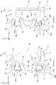
- FIGs 1a and 1b show a fenestration unit 100 comprising a window frame assembly 102 and a glazing unit 104.
- the glazing unit 104 comprises two panes of glass 108 spaced apart and lying parallel to each other.
- the glazing unit 104 may comprise one or more than two panes of glass 108.
- the glazing unit 104 could be replaced with a panel of wood, aluminium or other suitable material. It shall be appreciated that although the glazing unit 104 in this embodiment is a double glazing unit, alternative glazing units, for example opaque panels, for example for doors, may be used.
- Fenestration units 100 of this type are typically used in external walls of domestic and commercial buildings. It is therefore necessary that the fenestration unit meets requirements for thermal insulation, sealing against water ingress, draughts etc.
- the glazing unit 104 is supported by the window frame assembly 102, which is in contact with two opposite faces of the glazing unit 104 along each border of the glazing unit 104.
- the window frame assembly 102 comprises four window frame members 103, each being made up of a plurality, in this case three, window frame sections, these being an elongate first structural section 106a, an elongate second structural section 106b and an elongate connector section 110.
- Each structural section 106a, 106b abuts an opposite face of the glazing unit 104 such that movement of the glazing unit 104 is restricted along the x-axis and along the y-axis in Figure 1b .
- the connector section 110 connects the first structural section 106a to the second structural section 106b and lies generally alongside but is spaced from an edge of the glazing unit 104.
- the connector section 110 is a single unitary component instead of two or more discrete "dog bones". By utilising a single unitary component, this may reduce the complexity of assembling the window frame assembly 102.
- the first structural section 106a comprises a glazing bead 101; shown schematically in Figure 1b .
- the glazing bead 101 may be formed as part of the second structural section 106b or may alternatively be releasably connected to the first structural section 106a.
- Figure 2 shows the first and second structural sections 106a, 106b and the connector section 110 exclusively.
- Each of the sections 106a, 106b, 110 has a corresponding longitudinal axis 112a, 112b, 124, which are all shown as being parallel to each other and extending into the page in Figure 2 ; i.e. along the z-axis.
- the first structural section 106a includes a first female portion 115a and a second female portion 115b along an edge of the first structural section 106a.
- the second structural section 106b includes a third female portion 115c and a fourth female portion 115d along an edge of the second structural section 106b.
- the female portions 115a, 115b, 115c, 115d each comprise a wall 114, a protrusion 118, and a cavity 122 defined by the respective wall 114 and the respective protrusion 118.
- each wall 114 is located along a corner of the respective structural section 106a, 106b and is movable from an open position (illustrated in Figure 4 ) to a closed position (illustrated in Figures 1b , 2 and 5 ).
- An inner face of the wall 114 is provided with a tooth 121 that has a point or tip facing generally inwardly.
- the connector section 110 includes a body 140 and four legs 142a, 142b, 142c, 142d extending away from the body 140.
- the body 140 includes two spaced apart transverse members 152 which are joined via a first cross-member 150a and a second cross-member 150b.
- the number of cross members 150 may differ in other embodiments e.g. one may be provided or three or more.
- the cross members 150a, 150b may additionally improve the thermal performance of the connector section 110 by reducing thermal transfer via convection across the frame member 103.
- a first leg 142a and a second leg 142b extend away the first cross-member 150a in a first direction substantially parallel to the x-axis in Figure 2 .
- a third leg 142c and a fourth leg 142d extend away from the second cross-member 150b in a second direction substantially parallel to the x-axis in Figure 2 and opposite to the first direction.
- the first leg 142a and the third leg 142c are spaced from the second leg 142b and the fourth leg 142d respectively along the y-axis.
- the x-axis is perpendicular to the longitudinal axis 124 of the connector section 110.
- the legs 142a, 142b, 142c, 142d all extend transversely to the longitudinal axis 124.
- the first leg 142a includes a first male portion 117a
- the second leg 142b includes a second male portion 117b
- the third leg 142c includes a third male portion 117c
- the fourth leg 142d includes a fourth male portion 117d.
- the first, second, third and fourth male portions 117a, 117b, 117c, 117d are all suitable for inter-engagement with the first, second, third and fourth female portions 115a, 115b, 115c, 115d respectively, as will be discussed more below.
- each male portion 117a, 117b, 117c, 117d comprises a boss 111, defining an outer undercut 116 and an inner undercut 119.
- An opening 120 is defined between the first male portion 117a and the second female portion 117b, and another opening 120 is defined between the third male portion 117c and the fourth male portion 117d.
- Each boss 111 has a leading edge (i.e. the edge of the boss 111 facing the cavity 122 in Figure 2 ) that it is wider relative to a trailing edge, and each undercut 116, 119 and each opening 120 is shaped to define each boss 111.
- each protrusion 118 has an obliquely angled cross-sectional profile and each opening 120 has a truncated bell-shaped cross-sectional profile.
- the combined width of the two protrusions 118 on the first structural section 106a where the protrusions 118 join the remainder of the first structural section 106a, is substantially equal to the width of the entrance of the opening 120 between the first male portion 117a and the second male portion 117b (where the width is defined as being aligned with the y-axis in Figure 2 ).
- the combined width of the two protrusions 118 on the second structural section 106b where the protrusions 118 join the remainder of the second structural section 106b is substantially equal to the width of the entrance of the opening 120 between the third male portion 117c and the fourth male portion 117d.
- each protrusion 118 and the corresponding openings 120 may have a different cross-sectional profile.
- each protrusion 118 may have a rectangular, triangular or any other shaped cross-sectional profile
- the corresponding opening 120 may have a rectangular, triangular or any other shaped cross-sectional profile.
- each male portion 117a, 117b, 117c, 117d has an identical geometry relative to each other.
- each female portion 115a, 115b, 115c, 115d has an identical geometry relative to each other, and each are symmetrical about a horizontal axis that is parallel to the x-axis in Figure 2 .
- one or more of the male portions 117a, 117b, 117c, 117d may not have an identical geometry relative to one or more of the others. Additionally or alternatively, one or more of the female portions 115a, 115b, 115c, 115d may not have an identical geometry relative to one or more of the others.
- the connector section 110 is a thermal insulation section that is formed from a more thermally insulative material than the first structural section 106a and the second structural section 106b.
- the first structural section 106a and the second structural section 106b are formed from an aluminium alloy and the connector section 110 is formed from a plastics material.
- the connector section 110 is formed from unplasticized polyvinyl chloride (uPVC). It has been determined that forming the connector section 110 from uPVC provides the connector section 110 with more than sufficient material strength and material thermal insulation properties. It is preferred to form the connector section 110 from uPVC relative to other plastics materials, since uPVC tends to be lower cost to produce relative to comparable plastics materials, such as polyamides for example.
- uPVC unplasticized polyvinyl chloride
- An example of a suitable uPVC based material is Thermavic RTM manufactured by Benvic SAS of Chevigny- Saint-Sauveur, France.
- the structural sections 106a, 106b and the connector section 110 may be formed from any suitable materials.
- the structural sections 106a, 106b may be formed from an alternative metallic material.
- the connector section 110 may be formed from an alternative plastics material such as a polyamide for example.
- the structural sections 106a, 106b and the connector section 110 all have a constant cross-sectional profile along their respective longitudinal axes 112a, 112b, 124.
- the structural sections 106a, 106b and the connector section 110 may be formed via extrusion.
- one or more of the structural sections 106a, 106b and the connector section 110 may not have a constant cross-sectional profile along their respective longitudinal axes 112a, 112b, 124.
- the body 140 of the connector section 110 may have a varying cross-sectional profile along the longitudinal axis 124.
- Figure 3 shows the connector section 110 exclusively.
- first leg 142a includes a first stem portion 146a interposed between the body 140 and the first male portion 117a.
- the second leg 142b includes a second stem portion 146b interposed between the body 140 and the second male portion 117b.
- the third leg 142c includes a third stem portion 146c interposed between the body 140 and the third male portion 117c.
- the fourth leg 142d includes a fourth stem portion 146d interposed between the body 140 and the fourth male portion 117d.
- Each stem portion 146a, 146b, 146c, 146d is secured to the body 140.
- the first stem portion 146a and the second stem portion 146b are secured to and extend from the first cross-member 150a.
- the third stem portion 146c and the fourth stem portion 146d are secured to and extend from the second cross-member 150b.
- the second leg 142b incudes a flexible portion 144.
- the flexible portion 144 is configured such that the second leg 142b is more flexible in bending relative to the first leg 142a.
- the fourth leg 142d includes a flexible portion 144 is configured such that the fourth leg 142d is more flexible in bending relative to the third leg 142c.
- the flexible portion 144 of the second leg 142b is substantially identical to the flexible portion 144 of the fourth leg 142d. In the following, unless stated otherwise, only the flexible portion 144 of the second leg 142b will be discussed. This discussion will apply equally to the flexible portion 144 of the fourth leg 142.
- the flexible portion 144 of the second leg 142b is configured such that the second male portion 117b is pivotable about the flexible portion 144. As shown in Figure 3 , the second male portion 117b is pivotable about the flexible portion 144 relative to the body 140 between a first position P1 (shown in phantom) and a second position P2 (shown in solid lines).
- the flexible portion 144 of the second leg 142b is configured such that it has a lower second moment of area relative to the remainder of the second leg 142b. As such, the flexible portion 144 of the second leg 142b has a lower flexural rigidity relative to the remainder of the second leg 142b.
- this is achieved by reducing the thickness of the flexible portion 144 relative to the remainder of the second leg 142b.
- the flexible portion 144 has a minimum thickness T1.
- the thickness T1 is smaller relative to the minimum thickness of the remainder of the second leg 142b.
- remainder of the second leg 142b it is meant all of the second leg 142b except for the flexible portion 144.
- the second stem portion 146b of the second leg 142b includes the flexible portion 144.
- the flexible portion 144 is located at the end of the second stem portion 146b which joins the body 140, i.e. a root of the second leg 142b.
- the second leg 142b is secured to the body 140 via the flexible portion 144.
- this may maximise the range of movement of the second male portion 117b relative to the body 140.
- the flexible portion 144 may not be on or in the second stem portion 146b.
- the second male portion 117b may include the flexible portion 144, or the flexible portion 144 may be interposed between the second stem portion 146b and the second male portion 117b.
- the second leg 142b may not be secured to the body 140 via the flexible portion.
- the flexible portion 144 may be located in or on the second stem portion 146b and spaced from the end of the second stem portion 146b which joins the body 140, i.e. the root of the second leg 142b.
- the first stem portion 146a has a substantially constant thickness T2 along its length between the body 140 and the first male portion 117a. It is clear that the minimum thickness T1 of the flexible portion 144 is smaller than the thickness T2 of the first stem portion 146a. Moreover, the minimum thickness T1 of the flexible portion 144 is smaller than the minimum thickness of the entire first leg 142a. As such, the second leg 142b is more flexible in bending than the first leg 142a.
- the thickness T1 is in is in the range of 0.5 mm to 2.5 mm, preferably in the range of 1 mm to 2 mm, and more preferably 1.5 mm.
- the thickness T2 is in the range of 1 mm to 4 mm, preferably in the range of 2 mm to 3 mm, more preferably 2.5 mm.
- the first stem portion 146a may not have a substantially constant thickness along its length between the body 140 and the first male portion 117a; i.e. the first stem portion 146a may have a variable thickness.
- the minimum thickness T1 of the flexible portion 144 may be smaller than a minimum thickness of the first stem portion 146a.
- the minimum thickness of the first stem portion 146a may be in the range of 1 mm to 4 mm, preferably in the range of 2 mm to 3 mm, more preferably 2.5 mm.
- the flexural rigidity of the flexible portion 144 of the second leg 142b may be reduced relative to the remainder of the second leg 142b by additional or alternative means.
- the flexible portion 144 of the second leg 142b may be perforated along a direction parallel to the longitudinal axis 124.
- the flexible portion 144 of the second leg 142b may be formed from a different material to the remainder of the second leg 142b, said different material being more flexible relative to the material of the remainder of the second leg 142b.
- the material of the flexible portion 144 may or may not be weaker than the material of the remainder of the second leg 142b.
- a layer of non-slip material 148 (represented schematically as a dashed line) is secured to the first male portion 117a.
- the layer of non-slip material 148 is secured to at least a portion of the outer undercut 116 of the first male portion 117a.
- a layer of non-slip material 148 is secured to at least a portion of the outer undercut 116 of the third male portion 117c.
- a layer of non-slip material 148 is also secured to at least a portion of the outer undercut 116 of the second male portion 117b. Although not shown, it will be appreciated that a layer of non-slip material 148 may also be secured to at least a portion of the outer undercut 116 of the fourth male portion 117d.
- Each layer of non-slip material 148 is configured to increase the grip strength between the walls 114 (and in particular the teeth 121 thereof) and the respective outer undercuts 116 when the female portions 115a, 115b, 115c, 115d and the male portions 117a, 117b, 117c, 117d are interengaged, as will be discussed more below.
- each layer of non-slip material 148 is a layer of flexible polymeric material, such as a flexible polyvinyl chloride (PVC) or a thermoplastic elastomer (TPE), for example a thermoplastic rubber (TPR).
- PVC flexible polyvinyl chloride
- TPE thermoplastic elastomer
- TPR thermoplastic rubber
- the layers of flexible polymeric material can be compressed by and conform to the respective walls 114, which further improves the grip between the walls 114 and the layers of non-slip material 148, in particular in the z direction.
- Each layer of non-slip material 148 is a membrane which is arranged to cover at least a portion of the respective outer undercut 116.
- Each membrane has a thickness, as measured normal to the surface of the respective outer undercut 116 to which it is secured, typically in the range of 0.1 to 0.5mm, preferably in the range of 0.2 to 0.3mm.
- each layer of non-slip material 148 as a membrane helps to maximise the contact surface area between each layer of non-slip material 148 and the respective wall 114, without the need to modify the geometry of the male portions 117 or the female portions 115 to accommodate the layers of non-slip material 148.
- the material 148 is effectively clamped and cannot readily resile away from the wall 114 and tooth 121, further enhancing the grip.
- Each layer of non-slip material 148 is formed as an elongate strip which extends longitudinally (i.e. substantially parallel to the longitudinal axis 124) along the respective outer undercut 116. This helps to maximise the contact surface area between each layer of non-slip material 148 and the respective wall 114.
- Each layer of non-slip material 148 may extend along a majority of or all of the longitudinal length of the respective outer undercut 116. It will be appreciated that the layers of non-slip material 148 secured to the outer undercuts 116 may be of different lengths.
- Each layer of non-slip material 148 is an elongate strip having a width, as measured substantially transverse to the longitudinal axis 124, typically in the range of 1.0 to 5.0mm, preferably in the range of 2.0 to 3.0mm.
- each layer of non-slip material 148 is secured to the respective male portion 117a, 117b, 117c, 117d by coextruding the layer of non-slip material 148 with the respective male portion 117a, 117b, 117c, 117d.
- each layer of non-slip material 148 may be secured to the respective male portion 117a, 117b, 117c, 117d via any suitable means, such as via bonding or heat sealing for example.
- Each layer of non-slip material 148 is arranged to be proud of a surface or surfaces of the connector section 110 bordering said layer of non-slip material 148; i.e. each layer of non-slip material 148 protrudes relative to the surface or surfaces of the connector section 110 (e.g. the surface or surfaces of the respective outer undercut 116) directly adjacent the edges of the layer of non-slip material 148.
- this allows a greater surface area of each layer of non-slip material 148 to be compressed by the respective walls when the female portions 115a, 115b, 115c, 115d and the male portions 117a, 117b, 117c, 117d are interengaged, relative to if each layer of non-slip material 148 was flush with the surface or surfaces of the connector section 110 bordering said layer of non-slip material 148 for example.
- this results in a superior frictional engagement between the connector section 110 and the structural sections 106a, 106b.
- a layer of non-slip material 148 may be secured to only one of the male portions 117a, 117b, 117c, 117d, or any combination of two or three of the male portions 117a, 117b, 117c, 117d.
- no layer of non-slip material 148 may be secured to any of the male portions 117a, 117b, 117c, 117d.
- a layer of non-slip material 148 may be secured to one or more of the inner undercuts 119.
- first male portion 117a of the connector section 110 is received within the first female portion 115a of the first structural section 106a.
- second male portion 117b is received within the second female portion 115b.
- Figure 4 shows both male portions 117a, 117b after they have been received within the respective female portions 115a, 115b.
- the second male portion 117b is received in the second female portion 115b, the second male portion 117b is in the first position P1.
- a transverse axis 160b of the second male portion 117b is oriented at an obtuse angle A1 relative to a reference axis 162.
- the reference axis 162 is parallel to the y-axis.
- a transverse axis 160a of the first male portion 117a is oriented perpendicular to the reference axis 162, i.e. the transverse axis 160a is parallel to the x-axis.
- the transverse axis 160b of the second male portion 117b is oriented away from the transverse axis 160a of the first male portion 117a.
- the walls 114 of the first female portion 115a and the second female portion 115b are in their open positions.
- the first and the second male portions 117a, 117b are received within the first and the second female portions 115a, 115b respectively by first arranging the first structural section 106a and the connector section 110 such that their respective longitudinal axes 112a, 124 are parallel to each other, and such that a free end of the first structural section 106a faces a free end of the connector section 110. Subsequently, the first male portions 117a, 117b are received within the respective female portions 115a, 115b by translating/sliding the male portions 117a, 117b and the female portions 115a, 115b relative to each other along their respective longitudinal axes 112a, 124.
- Each male portion 117a, 117b is shaped such that it can be received within the corresponding female portion 115a, 115b along the longitudinal directions 112a, 124 when each wall 114 is in the open position and when the second male portion 117b is in the first position P1.
- the bosses 111 are able to enter and be fully received within the corresponding cavities 122.
- first and the second male portions 117a, 117b may be received within the first and the second female portions 115a, 115b respectively by first arranging the first structural section 106a and the connector section 110 such that their respective longitudinal axes 112a, 124 are parallel to each other and such that the first and the second male portions 117a, 117b are facing the first and the second female portions 115a, 115b respectively.
- the first male portions 117a, 117b may be received within the respective female portions 115a, 115b by translating the male portions 117a, 117b and the female portions 115a, 115b towards each other along the x-axis in Figures 4 and 5 , which is perpendicular to both of the longitudinal axes 112a, 124.
- the openings to the cavities 122 of the female portion 115a, 115b would need to be sufficiently sized to allow the male portions 117a, 117b to enter said cavities along the transverse direction, i.e. along the x-axis.
- the wall 114 of the first female portion 115a is moved from the open position to the closed position. Once the wall 114 is in the closed position, the wall 114 engages the outer undercut 116 of the first male portion 117a as shown in Figure 5 . This may be achieved, for example, by manually pressing the wall 114 until it engages the corresponding outer undercut 116. Alternatively or additionally, a tool or machine may be used to position the wall 114 until it engages the corresponding outer undercut 116.
- the wall 114 of the first female portion 115a and the outer undercut 116 of the first male portion 117a are shaped such that the first male portion 117a and the first female portion 115a are interengaged; i.e. the first male portion 117a and the first female portion 115a are mutually engaged in order to provide a connection between the sections 106a, 110.
- the wall 114 of the first female portion 115a abuts against the layer of non-slip material 116 as said wall 114 engages the outer undercut 116 of the first male portion 117a.
- the layer of non-slip material 116 improves the grip strength between the wall 114 of the first female portion 115a and the first male portion 117a, in particular so as to inhibit relative sliding in a longitudinal direction.
- the wall 114 of the first female portion 115a is configured to be mechanically retained in the outer undercut 116 of the first male portion 116a once positioned to engage said outer undercut 116. In the illustrated embodiment, this is achieved via a portion of the wall 114 being configured to plastically deform when positioned to engage the outer undercut 116. Either prior to, at the same time as or subsequent to the wall 117 of the first female portion 115a being positioned until it engages the outer undercut 116 of the first male portion 117a, the wall 114 of the second female portion 115b is moved from the open position to the closed position.
- the wall 114 of the second female portion 115b moves from the open position to the closed position, the wall 114 engages the outer undercut 116 of the second male portion 117b such that the second male portion 117b moves from the first position P1 shown in Figure 4 to the second position P2 shown in Figure 5 .
- This may be achieved, for example, by manually pressing the wall 114 until it engages the corresponding outer undercut 116.
- a tool or machine may be used to position the wall 114 until it engages the corresponding outer undercut 116.
- the wall 114 of the second female portion 115b and the outer undercut 116 of the second male portion 117b are shaped such that the second male portion 117b and the second female portion 115b are interengaged.
- the transverse axis 160b of the second male portion 117b is oriented at an angle A2 relative to the reference axis 162, which is parallel to the y-axis.
- the transverse axis 160b is perpendicular to the reference axis 162, i.e. the angle A2 is ninety degrees.
- the transverse axis 160a of the first male portion 117a is parallel to the transverse axis 160b of the second male portion 117b, and is therefore parallel to the x-axis.
- the second male portion 117b is moved from the first position P1 to the second position P2, the second male portion 117b is moved towards the first male portion 117a.
- the wall 114 of the second female portion 115b abuts against the layer of non-slip material 116 as said wall 114 engages the outer undercut 116 of the second male portion 117b.
- the layer of non-slip material 116 improves the grip strength between the wall 114 of the second female portion 115b and the second male portion 117b, in particular so as to inhibit relative sliding in a longitudinal direction.
- the wall 114 of the second female portion 115b is configured to be mechanically retained in the outer undercut 116 of the second male portion 117b once positioned to engage said outer undercut 116. In the illustrated embodiment, this is achieved via a portion of the wall 114 being configured to plastically deform when positioned to engage the outer undercut 116.
- the sections 106a, 106b, 110 of the finished profile are generally level and the longitudinal axes 112a, 112b, 124 of the sections 106a, 106b, 110 are substantially parallel to each other.
- Unwanted distortions arise when portions of two or more of the sections 106a, 106b, 110 of the finished profile are not level with each other due to local divergence of the longitudinal axes 112a, 112b, 124 of those sections 106a, 106b, 110. It will be appreciated that such distortions may prevent proper fitting of the finished profile to the remainder of the fenestration unit 100.
- unwanted distortions may inhibit beads (for example the bead 101 in Figure 1b ) and other components from being secured to the finished profile, or sealing between components being adequate.
- the transverse axis 160a of the first male portion 117a may not be perpendicular to the reference axis 162. Additionally or alternatively, the transverse axis 160a of the first male portion 117a and the transverse axis 160b of the second male portion 117b may not be parallel when the second male portion 117b is in the second position P2.
- the positions of the wall 114 and the protrusion 118 on the second female portion 115b may be reversed, and the positions of the outer and the inner undercuts 116, 119 on the second male portion 117b may be reversed accordingly.
- the transverse axis 160b of the second male portion 117b may move away from the transverse axis 160a of the first male portion 117a as the wall 114 of the second female portion 115b engages the outer undercut 116 of the second male portion 117b such that the second male portion 117b moves from the first position P1 to the second position P2.
- the positions of the wall 114 and the protrusion 118 on the first female portion 115a may be reversed, and the position of the outer and the inner undercuts 116, 119 on the first male portion 117a may be reversed accordingly.
- a tool or machine may be inserted internally between the connector section 110 and the first structural section 106a to position the wall/walls 114 to engage the corresponding undercut/undercuts 116.
- Figure 1b shows the window frame assembly 102 in which the connector section 110 has been connected to both the first structural section 106a and the second structural section 106b via the foregoing method.
- the second leg 142b is made to be more flexible in bending than the first leg 142b by providing the second leg 142b with the flexible portion 144.
- the second leg 142b may not include the flexible portion 144.
- the body 140 of the connector section 110 may be configured to such that the second leg 142b is more flexible in bending than the first leg 142a.
- the portion of the body 140 to which the second leg 142b joins may be formed from a more flexible material relative to the portion of the body 140 to which the first leg 142a joins.
- the means which allows the second leg 142b to be more flexible in bending relative to the first leg 142a may be different to the means which allows the fourth leg 142d to be more flexible in bending relative to the third leg 142c.
- structural sections 106a, 106b each comprising two walls 114 and connector sections 110 comprising four corresponding undercuts 116 have been disclosed.
- the structural sections 106a, 106b may each comprise one or more than two walls 114 and the connector section 110 may comprise one, two, three or more than four corresponding undercuts 116.
- structural sections 106a, 106b each comprising two protrusions 118have been disclosed.
- one or both of the structural sections 106a, 106b may comprise only one protrusion 118 which is suitably shaped to be receivable within one of the openings 120 of the connector section 110.
- the single protrusion 118 on one or both of the structural section 106a, 106b may be shaped to at least partially define the female portions 115a, 115b, 115c, 115d of the corresponding structural section 106a, 106b.
- female portions 115a, 115b, 115c, 115d each comprising one cavity 122 and male portions 117a, 117b, 117c, 117d each comprising one boss 111
- the female portions 115a, 115b, 115c, 115d and the corresponding male portion 117a, 117b, 117c, 117d may be of any shape, so long as each male portion 117a, 117b, 117c, 117d is shaped to at least partially conform to the respective female portion 115a, 115b, 115c, 115d when each wall 114 is in the closed position, when the second and fourth male portions 117b, 117d are in the second position P2, and when the structural sections' 112a, 112b longitudinal axes 112a, 112b is parallel to the connector section's 110 longitudinal axis 124.
Landscapes
- Engineering & Computer Science (AREA)
- Civil Engineering (AREA)
- Structural Engineering (AREA)
- Wing Frames And Configurations (AREA)
Applications Claiming Priority (2)
| Application Number | Priority Date | Filing Date | Title |
|---|---|---|---|
| GB2101201.8A GB2604579B (en) | 2021-01-28 | 2021-01-28 | A window frame assembly |
| GB2104484.7A GB2603213A (en) | 2021-01-28 | 2021-03-30 | A window frame assembly |
Publications (1)
| Publication Number | Publication Date |
|---|---|
| EP4036360A1 true EP4036360A1 (de) | 2022-08-03 |
Family
ID=80121756
Family Applications (2)
| Application Number | Title | Priority Date | Filing Date |
|---|---|---|---|
| EP22153749.1A Withdrawn EP4036361A1 (de) | 2021-01-28 | 2022-01-27 | Eine fensterrahmen-montage |
| EP22153748.3A Pending EP4036360A1 (de) | 2021-01-28 | 2022-01-27 | Eine fensterrahmen-montage |
Family Applications Before (1)
| Application Number | Title | Priority Date | Filing Date |
|---|---|---|---|
| EP22153749.1A Withdrawn EP4036361A1 (de) | 2021-01-28 | 2022-01-27 | Eine fensterrahmen-montage |
Country Status (1)
| Country | Link |
|---|---|
| EP (2) | EP4036361A1 (de) |
Citations (5)
| Publication number | Priority date | Publication date | Assignee | Title |
|---|---|---|---|---|
| DE2534818A1 (de) * | 1975-08-05 | 1977-02-10 | Peter Bayerl | Thermisch unterteiltes metallprofil zur anwendung in bauwerken |
| DE3545092A1 (de) * | 1985-10-17 | 1987-04-30 | Gartner & Co J | Verbundprofil |
| EP0657612A1 (de) * | 1993-12-02 | 1995-06-14 | Lorenzo Diaz Maricurreina | Modularsystem zur Herstellung von Verglasungen |
| US5469683A (en) * | 1994-02-09 | 1995-11-28 | Kawneer Company, Inc. | Thermally insulating composite frame member with snap-in thermal isolator |
| WO2004079139A1 (en) * | 2003-03-05 | 2004-09-16 | Strato S.R.L. | Multiple structure profile for door and window frames provided with outer interchangeable section bars |
Family Cites Families (3)
| Publication number | Priority date | Publication date | Assignee | Title |
|---|---|---|---|---|
| DE10063894A1 (de) * | 2000-12-21 | 2002-06-27 | Joma Polytec Kunststofftechnik | Dämmleiste aus einem Kunststoff hoher Festigkeit zur gegenseitigen Verbindung zweier Metallprofile zu einem Verbundprofil |
| CN103132860A (zh) * | 2013-03-19 | 2013-06-05 | 广州澳普利发门窗系统有限公司 | 一种具有双边隔热断桥结构的节能型框 |
| CN108179951A (zh) * | 2018-01-25 | 2018-06-19 | 池州市九华明坤铝业有限公司 | 一种隔热铝合金型材 |
-
2022
- 2022-01-27 EP EP22153749.1A patent/EP4036361A1/de not_active Withdrawn
- 2022-01-27 EP EP22153748.3A patent/EP4036360A1/de active Pending
Patent Citations (5)
| Publication number | Priority date | Publication date | Assignee | Title |
|---|---|---|---|---|
| DE2534818A1 (de) * | 1975-08-05 | 1977-02-10 | Peter Bayerl | Thermisch unterteiltes metallprofil zur anwendung in bauwerken |
| DE3545092A1 (de) * | 1985-10-17 | 1987-04-30 | Gartner & Co J | Verbundprofil |
| EP0657612A1 (de) * | 1993-12-02 | 1995-06-14 | Lorenzo Diaz Maricurreina | Modularsystem zur Herstellung von Verglasungen |
| US5469683A (en) * | 1994-02-09 | 1995-11-28 | Kawneer Company, Inc. | Thermally insulating composite frame member with snap-in thermal isolator |
| WO2004079139A1 (en) * | 2003-03-05 | 2004-09-16 | Strato S.R.L. | Multiple structure profile for door and window frames provided with outer interchangeable section bars |
Also Published As
| Publication number | Publication date |
|---|---|
| EP4036361A1 (de) | 2022-08-03 |
Similar Documents
| Publication | Publication Date | Title |
|---|---|---|
| US8683694B1 (en) | Method of forming a frame assembly | |
| US7047576B2 (en) | Plastic profile | |
| US20080202035A1 (en) | Water-tight windows with preformed corners | |
| US20050115178A1 (en) | Corner key for connecting profiles together and frame work assembly | |
| KR940021884A (ko) | 맞댐 이음 장치 | |
| CA2423143C (en) | A joint arrangement for demountable structure | |
| KR20190033179A (ko) | 다중구조의 방화문 프레임 결합구조 | |
| EP4036360A1 (de) | Eine fensterrahmen-montage | |
| GB2604579A (en) | A window frame assembly | |
| GB2513947A (en) | Gasket | |
| RU2125640C1 (ru) | Пластмассовый рамный профиль с уплотнительной прокладкой | |
| GB2580504A (en) | Glazing frame | |
| US12116829B1 (en) | Fenestration assembly mull joints with improved strength and methods | |
| GB2578909A (en) | Bead assembly | |
| GB2622442A (en) | A window frame assembly | |
| EP1499788A1 (de) | Verbundprofil für tür- und fensterrahmen | |
| GB2487910A (en) | Corner connector and frame assembly | |
| EP3854978A1 (de) | Verfahren | |
| RU2250336C1 (ru) | Система профилей для сборки оконных и/или дверных блоков | |
| JP7012537B2 (ja) | 二重サッシ | |
| JP3492047B2 (ja) | 断熱型材 | |
| JP7331173B2 (ja) | 建具 | |
| CN216841271U (zh) | 一种柔性的门窗型材 | |
| RU26068U1 (ru) | Пластмассовый профиль для сборки блоков для закрытия оконных и/или дверных проемов | |
| JP5996366B2 (ja) | 合成樹脂製パネル用枠部材 |
Legal Events
| Date | Code | Title | Description |
|---|---|---|---|
| PUAI | Public reference made under article 153(3) epc to a published international application that has entered the european phase |
Free format text: ORIGINAL CODE: 0009012 |
|
| STAA | Information on the status of an ep patent application or granted ep patent |
Free format text: STATUS: THE APPLICATION HAS BEEN PUBLISHED |
|
| AK | Designated contracting states |
Kind code of ref document: A1 Designated state(s): AL AT BE BG CH CY CZ DE DK EE ES FI FR GB GR HR HU IE IS IT LI LT LU LV MC MK MT NL NO PL PT RO RS SE SI SK SM TR |
|
| STAA | Information on the status of an ep patent application or granted ep patent |
Free format text: STATUS: REQUEST FOR EXAMINATION WAS MADE |
|
| 17P | Request for examination filed |
Effective date: 20230203 |
|
| RBV | Designated contracting states (corrected) |
Designated state(s): AL AT BE BG CH CY CZ DE DK EE ES FI FR GB GR HR HU IE IS IT LI LT LU LV MC MK MT NL NO PL PT RO RS SE SI SK SM TR |