EP4036307B1 - Appareil et procédé de préparation d'un produit de réseau de fibres biodégradables tridimensionnel de fibres organiques naturelles - Google Patents
Appareil et procédé de préparation d'un produit de réseau de fibres biodégradables tridimensionnel de fibres organiques naturelles Download PDFInfo
- Publication number
- EP4036307B1 EP4036307B1 EP22154829.0A EP22154829A EP4036307B1 EP 4036307 B1 EP4036307 B1 EP 4036307B1 EP 22154829 A EP22154829 A EP 22154829A EP 4036307 B1 EP4036307 B1 EP 4036307B1
- Authority
- EP
- European Patent Office
- Prior art keywords
- mould
- electromagnetic energy
- pores
- natural organic
- aqueous solution
- Prior art date
- Legal status (The legal status is an assumption and is not a legal conclusion. Google has not performed a legal analysis and makes no representation as to the accuracy of the status listed.)
- Active
Links
- 238000000034 method Methods 0.000 title claims description 82
- 239000000835 fiber Substances 0.000 title claims description 77
- 238000002360 preparation method Methods 0.000 title claims description 11
- 239000000047 product Substances 0.000 claims description 95
- 239000011148 porous material Substances 0.000 claims description 85
- 239000006260 foam Substances 0.000 claims description 45
- 239000007864 aqueous solution Substances 0.000 claims description 36
- 239000007788 liquid Substances 0.000 claims description 23
- 239000000654 additive Substances 0.000 claims description 21
- 229920002678 cellulose Polymers 0.000 claims description 18
- 239000001913 cellulose Substances 0.000 claims description 18
- 230000005672 electromagnetic field Effects 0.000 claims description 17
- 238000004519 manufacturing process Methods 0.000 claims description 15
- 238000005187 foaming Methods 0.000 claims description 14
- 229920001817 Agar Polymers 0.000 claims description 10
- 229920001661 Chitosan Polymers 0.000 claims description 10
- 230000000996 additive effect Effects 0.000 claims description 10
- 229940080421 coco glucoside Drugs 0.000 claims description 10
- 238000009826 distribution Methods 0.000 claims description 10
- 239000008272 agar Substances 0.000 claims description 9
- 239000012467 final product Substances 0.000 claims description 9
- 150000004676 glycans Chemical class 0.000 claims description 8
- 229920005610 lignin Polymers 0.000 claims description 8
- 229920001282 polysaccharide Polymers 0.000 claims description 8
- 239000005017 polysaccharide Substances 0.000 claims description 8
- 239000003989 dielectric material Substances 0.000 claims description 7
- 239000004604 Blowing Agent Substances 0.000 claims description 6
- 230000005670 electromagnetic radiation Effects 0.000 claims description 5
- 238000011049 filling Methods 0.000 claims description 5
- 229910052751 metal Inorganic materials 0.000 claims description 5
- 239000002184 metal Substances 0.000 claims description 5
- 239000003381 stabilizer Substances 0.000 claims description 5
- 239000013590 bulk material Substances 0.000 claims description 4
- 230000001419 dependent effect Effects 0.000 claims description 4
- 239000004094 surface-active agent Substances 0.000 claims description 2
- XLYOFNOQVPJJNP-UHFFFAOYSA-N water Substances O XLYOFNOQVPJJNP-UHFFFAOYSA-N 0.000 description 57
- 239000000463 material Substances 0.000 description 37
- 238000001035 drying Methods 0.000 description 18
- 239000000243 solution Substances 0.000 description 17
- 239000012071 phase Substances 0.000 description 16
- 230000008569 process Effects 0.000 description 15
- 229920003043 Cellulose fiber Polymers 0.000 description 12
- 239000000203 mixture Substances 0.000 description 10
- 239000011230 binding agent Substances 0.000 description 8
- 238000009835 boiling Methods 0.000 description 8
- 239000007789 gas Substances 0.000 description 8
- 239000004088 foaming agent Substances 0.000 description 7
- 239000000123 paper Substances 0.000 description 7
- QTBSBXVTEAMEQO-UHFFFAOYSA-N Acetic acid Chemical compound CC(O)=O QTBSBXVTEAMEQO-UHFFFAOYSA-N 0.000 description 6
- CDBYLPFSWZWCQE-UHFFFAOYSA-L Sodium Carbonate Chemical compound [Na+].[Na+].[O-]C([O-])=O CDBYLPFSWZWCQE-UHFFFAOYSA-L 0.000 description 6
- 239000004872 foam stabilizing agent Substances 0.000 description 6
- 238000009423 ventilation Methods 0.000 description 6
- 244000025254 Cannabis sativa Species 0.000 description 5
- 235000012766 Cannabis sativa ssp. sativa var. sativa Nutrition 0.000 description 5
- 235000012765 Cannabis sativa ssp. sativa var. spontanea Nutrition 0.000 description 5
- 230000015572 biosynthetic process Effects 0.000 description 5
- 235000009120 camo Nutrition 0.000 description 5
- 239000003990 capacitor Substances 0.000 description 5
- 235000005607 chanvre indien Nutrition 0.000 description 5
- 238000001704 evaporation Methods 0.000 description 5
- 230000008020 evaporation Effects 0.000 description 5
- 239000011487 hemp Substances 0.000 description 5
- 239000000725 suspension Substances 0.000 description 5
- 229920002472 Starch Polymers 0.000 description 4
- 238000010438 heat treatment Methods 0.000 description 4
- 239000008107 starch Substances 0.000 description 4
- 235000019698 starch Nutrition 0.000 description 4
- 241000196324 Embryophyta Species 0.000 description 3
- 239000004809 Teflon Substances 0.000 description 3
- 229920006362 Teflon® Polymers 0.000 description 3
- 230000015556 catabolic process Effects 0.000 description 3
- 238000006731 degradation reaction Methods 0.000 description 3
- 239000002657 fibrous material Substances 0.000 description 3
- 229910000029 sodium carbonate Inorganic materials 0.000 description 3
- 239000002904 solvent Substances 0.000 description 3
- 239000012855 volatile organic compound Substances 0.000 description 3
- 229920000936 Agarose Polymers 0.000 description 2
- MHAJPDPJQMAIIY-UHFFFAOYSA-N Hydrogen peroxide Chemical compound OO MHAJPDPJQMAIIY-UHFFFAOYSA-N 0.000 description 2
- 235000008331 Pinus X rigitaeda Nutrition 0.000 description 2
- 235000011613 Pinus brutia Nutrition 0.000 description 2
- 241000018646 Pinus brutia Species 0.000 description 2
- 238000010521 absorption reaction Methods 0.000 description 2
- 238000007605 air drying Methods 0.000 description 2
- 230000008901 benefit Effects 0.000 description 2
- 230000008859 change Effects 0.000 description 2
- 238000010924 continuous production Methods 0.000 description 2
- 238000001914 filtration Methods 0.000 description 2
- 238000009413 insulation Methods 0.000 description 2
- 230000010354 integration Effects 0.000 description 2
- 230000003993 interaction Effects 0.000 description 2
- BDAGIHXWWSANSR-UHFFFAOYSA-N methanoic acid Natural products OC=O BDAGIHXWWSANSR-UHFFFAOYSA-N 0.000 description 2
- 238000002156 mixing Methods 0.000 description 2
- 239000003607 modifier Substances 0.000 description 2
- 230000008635 plant growth Effects 0.000 description 2
- 229920001343 polytetrafluoroethylene Polymers 0.000 description 2
- 239000004810 polytetrafluoroethylene Substances 0.000 description 2
- 239000002994 raw material Substances 0.000 description 2
- 238000007493 shaping process Methods 0.000 description 2
- 239000007787 solid Substances 0.000 description 2
- 238000005728 strengthening Methods 0.000 description 2
- 239000000126 substance Substances 0.000 description 2
- 239000013598 vector Substances 0.000 description 2
- 239000002023 wood Substances 0.000 description 2
- OSWFIVFLDKOXQC-UHFFFAOYSA-N 4-(3-methoxyphenyl)aniline Chemical compound COC1=CC=CC(C=2C=CC(N)=CC=2)=C1 OSWFIVFLDKOXQC-UHFFFAOYSA-N 0.000 description 1
- 241000894006 Bacteria Species 0.000 description 1
- 229920002261 Corn starch Polymers 0.000 description 1
- 239000001856 Ethyl cellulose Substances 0.000 description 1
- ZZSNKZQZMQGXPY-UHFFFAOYSA-N Ethyl cellulose Chemical compound CCOCC1OC(OC)C(OCC)C(OCC)C1OC1C(O)C(O)C(OC)C(CO)O1 ZZSNKZQZMQGXPY-UHFFFAOYSA-N 0.000 description 1
- 240000006240 Linum usitatissimum Species 0.000 description 1
- 235000004431 Linum usitatissimum Nutrition 0.000 description 1
- 239000004696 Poly ether ether ketone Substances 0.000 description 1
- 229920001131 Pulp (paper) Polymers 0.000 description 1
- UIIMBOGNXHQVGW-DEQYMQKBSA-M Sodium bicarbonate-14C Chemical compound [Na+].O[14C]([O-])=O UIIMBOGNXHQVGW-DEQYMQKBSA-M 0.000 description 1
- 229920002522 Wood fibre Polymers 0.000 description 1
- 239000002250 absorbent Substances 0.000 description 1
- 230000002745 absorbent Effects 0.000 description 1
- 230000009471 action Effects 0.000 description 1
- 238000004026 adhesive bonding Methods 0.000 description 1
- 230000002776 aggregation Effects 0.000 description 1
- 238000004220 aggregation Methods 0.000 description 1
- JUPQTSLXMOCDHR-UHFFFAOYSA-N benzene-1,4-diol;bis(4-fluorophenyl)methanone Chemical compound OC1=CC=C(O)C=C1.C1=CC(F)=CC=C1C(=O)C1=CC=C(F)C=C1 JUPQTSLXMOCDHR-UHFFFAOYSA-N 0.000 description 1
- 230000003115 biocidal effect Effects 0.000 description 1
- 230000008049 biological aging Effects 0.000 description 1
- 230000004071 biological effect Effects 0.000 description 1
- 239000012620 biological material Substances 0.000 description 1
- 229920003086 cellulose ether Polymers 0.000 description 1
- 239000000919 ceramic Substances 0.000 description 1
- 239000003795 chemical substances by application Substances 0.000 description 1
- 238000005056 compaction Methods 0.000 description 1
- 230000006835 compression Effects 0.000 description 1
- 238000007906 compression Methods 0.000 description 1
- 238000010276 construction Methods 0.000 description 1
- 239000008120 corn starch Substances 0.000 description 1
- 230000003247 decreasing effect Effects 0.000 description 1
- 238000010586 diagram Methods 0.000 description 1
- 230000004069 differentiation Effects 0.000 description 1
- 238000007599 discharging Methods 0.000 description 1
- 238000006073 displacement reaction Methods 0.000 description 1
- 230000000694 effects Effects 0.000 description 1
- 238000005265 energy consumption Methods 0.000 description 1
- 238000005516 engineering process Methods 0.000 description 1
- 239000003623 enhancer Substances 0.000 description 1
- 230000007613 environmental effect Effects 0.000 description 1
- 235000010944 ethyl methyl cellulose Nutrition 0.000 description 1
- 230000002349 favourable effect Effects 0.000 description 1
- 230000004720 fertilization Effects 0.000 description 1
- 239000012530 fluid Substances 0.000 description 1
- -1 for example Polymers 0.000 description 1
- 235000019253 formic acid Nutrition 0.000 description 1
- 239000012634 fragment Substances 0.000 description 1
- 230000006870 function Effects 0.000 description 1
- 229940065115 grapefruit extract Drugs 0.000 description 1
- 230000012010 growth Effects 0.000 description 1
- 238000007731 hot pressing Methods 0.000 description 1
- 230000002209 hydrophobic effect Effects 0.000 description 1
- 239000001866 hydroxypropyl methyl cellulose Substances 0.000 description 1
- 229920003088 hydroxypropyl methyl cellulose Polymers 0.000 description 1
- 235000010979 hydroxypropyl methyl cellulose Nutrition 0.000 description 1
- UFVKGYZPFZQRLF-UHFFFAOYSA-N hydroxypropyl methyl cellulose Chemical compound OC1C(O)C(OC)OC(CO)C1OC1C(O)C(O)C(OC2C(C(O)C(OC3C(C(O)C(O)C(CO)O3)O)C(CO)O2)O)C(CO)O1 UFVKGYZPFZQRLF-UHFFFAOYSA-N 0.000 description 1
- 238000007603 infrared drying Methods 0.000 description 1
- 229910052500 inorganic mineral Inorganic materials 0.000 description 1
- 239000002655 kraft paper Substances 0.000 description 1
- 238000011031 large-scale manufacturing process Methods 0.000 description 1
- 239000008258 liquid foam Substances 0.000 description 1
- 239000007791 liquid phase Substances 0.000 description 1
- 238000013017 mechanical damping Methods 0.000 description 1
- 230000007246 mechanism Effects 0.000 description 1
- 229920000609 methyl cellulose Polymers 0.000 description 1
- 239000001923 methylcellulose Substances 0.000 description 1
- 235000010981 methylcellulose Nutrition 0.000 description 1
- 229920003087 methylethyl cellulose Polymers 0.000 description 1
- 239000011707 mineral Substances 0.000 description 1
- 235000010755 mineral Nutrition 0.000 description 1
- 239000011490 mineral wool Substances 0.000 description 1
- 238000000465 moulding Methods 0.000 description 1
- 238000009740 moulding (composite fabrication) Methods 0.000 description 1
- 239000005416 organic matter Substances 0.000 description 1
- 238000013021 overheating Methods 0.000 description 1
- 238000004806 packaging method and process Methods 0.000 description 1
- 239000002245 particle Substances 0.000 description 1
- 230000000704 physical effect Effects 0.000 description 1
- 229920002530 polyetherether ketone Polymers 0.000 description 1
- 229920000642 polymer Polymers 0.000 description 1
- 239000000843 powder Substances 0.000 description 1
- 238000003825 pressing Methods 0.000 description 1
- 238000012545 processing Methods 0.000 description 1
- 230000002035 prolonged effect Effects 0.000 description 1
- 230000002787 reinforcement Effects 0.000 description 1
- 238000011160 research Methods 0.000 description 1
- 239000006254 rheological additive Substances 0.000 description 1
- 229910052710 silicon Inorganic materials 0.000 description 1
- 239000010703 silicon Substances 0.000 description 1
- 239000001488 sodium phosphate Substances 0.000 description 1
- 229910000162 sodium phosphate Inorganic materials 0.000 description 1
- 239000000758 substrate Substances 0.000 description 1
- 238000012546 transfer Methods 0.000 description 1
- 230000007704 transition Effects 0.000 description 1
- RYFMWSXOAZQYPI-UHFFFAOYSA-K trisodium phosphate Chemical compound [Na+].[Na+].[Na+].[O-]P([O-])([O-])=O RYFMWSXOAZQYPI-UHFFFAOYSA-K 0.000 description 1
- 238000002604 ultrasonography Methods 0.000 description 1
Images


Classifications
-
- D—TEXTILES; PAPER
- D21—PAPER-MAKING; PRODUCTION OF CELLULOSE
- D21J—FIBREBOARD; MANUFACTURE OF ARTICLES FROM CELLULOSIC FIBROUS SUSPENSIONS OR FROM PAPIER-MACHE
- D21J3/00—Manufacture of articles by pressing wet fibre pulp, or papier-mâché, between moulds
Definitions
- cellulose fibres used as raw material are wetted, converted into a pulp, pressed, and dried giving sheets of paper having a substantially flat shape, wherein the fibres are oriented substantially in the sheet-plane direction, which results in a product having a good tensile strength in said sheet-plane direction. Compression into thin sheets of paper allows for effective removal of water from the material, whereas production of thicker sheets is limited and requires more energy to dry the final product.
- Timofeev, et al. "Drying of foam-formed mats from virgin pine fibers", (2016), Drying Technology, 34:10, 1210-1218 , describes drying of foam-formed mats from virgin pine fibres using the steps of fibre foam preparation, draining of the liquid, and drying with the use of different drying methods, namely convective drying in the oven, impingement drying assisted by vacuum, combined impingement-infrared drying, and through-air drying. Shrinkage of the final product was observed in all tested drying methods with the lowest shrinkage observed for combined techniques.
- Wood fibres are widely used for the manufacturing of fibreboards (such as MDF or HDF), however, in order to obtain desired properties of the fibreboard, fibres are mixed with a synthetic binder and formed into panels by hot-pressing. Synthetic binders used in the production of fibreboards are not environmentally friendly and such materials have limited uses.
- US 2001024716A1 discloses a method of producing an open low-density absorbent fibrous structure comprising combining hydrophilic fibres with a structuring composition to form a mixture, said structuring composition comprising a binder material and a removable phase; producing a foam within said mixture and binding said fibres together with substantially water-insoluble bonds into a continuous, porous network, wherein said binder material stabilizes the porous network.
- Various noncompressive drying techniques including air drying and microwave drying are disclosed to evacuate removable phase. However, said drying techniques require that essentially all of the removable phase is transformed from a liquid phase into a vapour phase, which is either time consuming or expensive in terms of energy demand.
- WO 2018237279 discloses perforated structures such as molds for manufacturing fibre-based materials by passing gas or liquid through the perforated structure, where different sets of perforations are grouped in zones to form a shape that is conformal to the product, Examples of the products that may be obtained with said molds are limited to structures of relatively small thickness such as carton, trays, conformal packaging, feminine hygiene products or diapers.
- An aspect of the present invention is to provide an apparatus for the preparation of a three-dimensional biodegradable fibre network product using electromagnetic energy.
- references in the specification to "an embodiment”, “one embodiment”, “another embodiment”, etc., indicate that the embodiment described may include one or more features. Additionally, when features are described in connection with one embodiment, it should be understood that such features may also be used in connection with other embodiments whether or not explicitly described unless clearly stated to the contrary.
- the pores of the mould are small enough that evaporated liquid within the mould results in a pressure build-up within the mould by the application of the electromagnetic energy.
- the electromagnetic energy provider is thus preferentially capable of dielectrically heating the aqueous solution within the mould until steam is formed which causes the pressure build-up.
- the liquid and steam evacuate through the pores of the mould, thereby shaping the natural organic fibres into their three-dimensional network and drying the solution.
- a surface share of the pores with regard to the surface encapsulating the volume within the mould is small such that internal pressure can build up, wherein the ideal share is preferentially dependent on a size of the mould. This is the case because the surface to volume ratio differs among different mould volumes.
- the surface share of the pores is in an embodiment between 0.2% and 20%, preferably between 1% and 15% and most preferably between 4% and 12%.
- the surface share of the pores is in an embodiment between 0.5% and 40%, preferably between 2% and 20% and most preferably between 6% and 14%, and for the volume between 10 litres and 100 litres the surface share of the pores is in an embodiment between 1% and 60%, preferably between 4% and 40% and most preferably between 10% and 30%.
- the shape of the mould is considered in addition to its volume for determining the most appropriate surface share of the pores.
- controller component is configured to control the electromagnetic energy dependent on a distribution and/or size of the pores of the mould and a desired pressure within the mould.
- one hole (pore) with an area of 2 mm 2 is capable to suppress the flow of gas (steam) or fluid (water or liquid) less than two holes with the same surface sum, i.e., 1 mm 2 + 1 mm 2 .
- the pore size is between 0.2 mm and 3 mm, preferably between 0.5 mm and 2 mm and most preferably between 0.8 mm and 1.5 mm.
- the dielectric material does not interfere with the (alternating) electromagnetic field and allows that the electromagnetic energy is not absorbed by the mould but by the content of the mould.
- the mould comprises or consists of metal, wherein the mould is a functional part of the electromagnetic energy provider.
- the mould comprises or consists of metal, it may for instance help to generate an electromagnetic field for providing the electromagnetic energy.
- Fig. 6 illustrates different embodiments a), b), c) and d) of a mould integration with the electromagnetic energy provider, referred to as electromagnetic field delivery device (EM), in cross-sectional view:
- EM electromagnetic field delivery device
- the cavity is a closed cavity or a tunnel cavity and the electromagnetic radiation causing a dielectric heating is generated as appropriate based on the selected electromagnetic device.
- the wavelengths of the electromagnetic radiation are not particularly limited.
- a wavelength which acts to efficiently heat the foamed natural organic fibrous material is chosen.
- a frequency of the electromagnetic radiation is preferably chosen below 300 GHz and in particular between 10 MHz and 300 GHz.
- the mould limits at least part of the cavity such that the foamed natural organic fibres in aqueous solution fully fill the cavity of the electromagnetic energy provider.
- This example is illustrated in view a) of Fig. 6 .
- the mould is implemented as closed porous mould, wherein the final product is removed from the mould after opening the closed porous mould.
- the mould according to this embodiment may optionally integrate parts of the walls of the cavity of the electromagnetic energy provider or not. It may be used with closed cavity and tunnel cavity electromagnetic energy providers.
- the electromagnetic energy provider comprises two substantially parallel plates acting as electrodes. These electrodes can also be integral part of the mould and then comprise pores, cf. view d) of Fig. 6 , or be separate from the mould, cf. view c) of the mould.
- At least one of the faces of the mould is integrally formed by one of the electrodes.
- the mould is open in one spatial direction such as to enable continuous bulk material production along that direction.
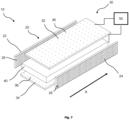
- FIG. 7 which further develops view d) of Fig. 6 , an exploded perspective view of an apparatus 10 for the preparation of a three-dimensional biodegradable fibre network product is illustrated.
- the apparatus 10 comprises a mould 20 which is partially integrated with a tunnel cavity of an electromagnetic energy provider 30.
- a bulk material 40 of foamed natural organic fibres in aqueous solution is inserted into the tunnel cavity along a direction indicated with an arrow A.
- the electromagnetic energy provider 30 comprises in this example two parallel plate electrodes 32, 34. Together with dielectric faces 22, 24 the material 40 is restricted in four directions and only direction A is open. The size of the open surfaces is small compared to the remaining surfaces such that pressure as desired can build up.
- Fig. 8 illustrates the apparatus 10 of Fig. 7 in an assembled view.
- a surface share of the pores with regard to the surface encapsulating the volume within the mould is small such that internal pressure can build up, wherein
- foaming natural organic fibres in aqueous solution is performed by introducing a gas into the pulp.
- the size and homogeneity of the foam bubbles are influenced by the different phases of the forming process.
- the stage of preparing the batch of material gives the possibility of shaping the character of the foam by adding to the mass some additives: blowing agents increase the amount of the gas filling the bubbles, surfactants control the foam's susceptibility to foaming.
- blowing agents increase the amount of the gas filling the bubbles
- surfactants control the foam's susceptibility to foaming.
- foam stabilizers allows the foam to maintain the desired properties until the fibres stiffen and take over the role of a supporting skeleton a structure that has so far been held by vanishing bubbles.
- non-fibrous additives can be used with the method of the present invention to define end parameters of the material.
- Some of the additives have a double role, as a material stabilizer and foam enhancers.
- biomaterials that are at least partially dissolvable in water are used.
- Preferred non-fibrous additives are agar and chitosan, polysaccharides, that are helping with moisture control and stiffness of the product.
- Agar gel acts as a foam stabilizer, that extends the life of wet foam, and after electromagnetic forming it acts as a gluing agent, improving the strength of bonds between fibres.
- aggregation and foaming of the natural organic fibres in aqueous solution is performed.
- foam creation There are many methods supporting the foam creation during this phase. It could be done by injecting a gas through nozzles, shaking/ultrasounds, mechanical mixing or increasing the gas saturation by increasing the pressure in the mixing chamber (generating overpressure relative to the forming process pressure).
- additional additives can be added.
- a ventilation system is used, allowing for removal of moisture from the space surrounding the form.
- the efficiency of the ventilation increases for shorter forming times (higher powers of electromagnetic energy can be applied).
- the delivery of warm air can further optimize the forming process in combination with the delivery of electromagnetic energy.
- Fig. 4 shows a cross section of the mould according to an embodiment (the same as shown in Fig. 3 and Fig. 4 ) with an indication of pressure gradients depending on mould shape and pore placements.
- the temperature of the foamy material inside the mould increases simultaneously throughout the entire volume of the mould. It is because EM energy is accumulated over the entire volume of foamy material, i.e. by all the mass contained in the mould.
- the temperature reaches the boiling point of water, an intense process of water vapor formation begins, the more intense the higher the power density used in the process. This creates a pressure build-up that seeks to escape through the pores in the mould walls.
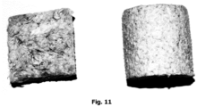
- Fragments of a final fibre network product obtained according to an embodiment, which was located adjacent to the flat walls in the regions corresponding to the pores in the mould have a greater density of the material, the fibre network product is strengthened, but only in a small area covered by the "action" of the mould pores. It is significant that from the side of the third flat wall, which is adjacent to the solid wall (without pores) of the mould, it is more difficult to distinguish a clear differentiation of density, the density gradient is absent, and the obtained fibre network product is softer.
- pores in bottom part of the mould could normally serve as drainage holes for water excess removal by gravitation or by additional application of vacuum.
- such process usually leads to some degradation of the foam.
- the draining step is not used and excess of water is forced out of the mould by application of electromagnetic energy at a level which causes water boiling inside the mould.
- parts of the mould or electromagnetic field delivery device have movable elements which allow automatizing the manufacturing process of material filling into the mould, travelling through the mould or removing it out of the mould after the formation of the final fibre network product.
- a three-dimensional biodegradable fibre network product prepared by the method according to the present invention is disclosed, but not claimed.
- Said product is prepared from foamed natural organic fibres using electromagnetic energy, wherein the fibre network product has a density of 8 - 150 kg/m 3 and total porosity of more than 90%.
- the product has a density of 8 - 90 kg/m 3 , preferably a density of 8 - 70 kg/m 3 , more preferably a density of 8 - 50 kg/m 3 , the most preferably a density of 8 - 30 kg/m 3 .
- the physical properties of the structure according to the disclosure can be determined by the method described by the Research Station in Naaldwijk, Netherlands (Wever '2002). Used standards: PN-EN 13039 - determination of organic matter content, PN-EN 13041 - determination of total porosity, volume density, shrinkage, water and air capacity at a water potential of -10 cm H 2 O.
- Fig. 5 shows water retention curve for the fibre network product according to an embodiment of the present invention.
- the X-axis represents a potential from 0 to -10 cm H 2 O
- the Y-axis represents water volume (vol %).
- the fibre network product according to the embodiment of the present invention is characterized by high water and air capacity of more than 45%, which favours the growth of young plants such as seedlings.
- the tested fibre network product in a form of cubes also have an appropriate pH of 6 - 7 and are characterized by a very low EC, which greatly facilitates the selection of optimal fertilization.
- the preferred density of the fibre network product is about 70 kg/m 3 (in the range of 65 - 75 kg/m 3 ).
- the fibre network product with such a density has the most advantageous air-water properties, similar to those of mineral wool.
- the three-dimensional biodegradable fibre network product of the present disclosure can be preferably used as a plant growth substrate, filtration medium, filling and/or acoustic and mechanical damping structure.
- the product was prepared according to the following steps:
- the method presented in example 1 makes it possible to obtain structures with high mechanical strength and high impact strength in relation to their mass.
- the highest density gradient is at the outer walls of the product and reaches 15 kg/m 3 on each 1 mm towards outside direction.
- the method in example 2 allows to obtain a material with higher flexibility and is characterized by high acoustic insulation.
- the product was prepared according to the following steps:
- the method provided in example 3 allows to obtain a material with good water absorption and favourable air-water relation for plant growth.
Landscapes
- Engineering & Computer Science (AREA)
- Manufacturing & Machinery (AREA)
- Nonwoven Fabrics (AREA)
Claims (26)
- Appareil de préparation d'un produit de réseau tridimensionnel fibreux biodégradable, l'appareil comprenant :un moule comprenant une pluralité de pores et conçu pour être rempli de fibres organiques naturelles moussées en solution aqueuse ;un fournisseur d'énergie électromagnétique destiné à fournir de l'énergie électromagnétique aux fibres organiques naturelles moussées à l'intérieur du moule ; etun composant de dispositif de commande conçu pour réguler l'énergie électromagnétique fournie par le fournisseur d'énergie électromagnétique afin de réguler une accumulation de pression à l'intérieur du moule, le produit de réseau tridimensionnel fibreux biodégradable étant préparé sur la base de l'évacuation de liquide et de vapeur à partir du moule à travers les pores par l'énergie électromagnétique fournie.
- Appareil selon la revendication 1, une part surfacique des pores par rapport à la surface encapsulant le volume à l'intérieur du moule étant petite de telle sorte qu'une pression interne peut s'accumuler,a. pour un volume de moule interne allant jusqu'à 1 litre, la part surfacique des pores étant située entre 0,2 % et 20 %, de préférence entre 1 % et 15 % et le plus préférablement entre 4 % et 12 %,b. pour le volume situé entre 1 litre et 10 litres, la part surfacique des pores étant située entre 0,5 % et 40 %, de préférence entre 2 % et 20 % et le plus préférablement entre 6 % et 14 % etc. pour le volume situé entre 10 litres et 100 litres, la part surfacique des pores étant située entre 1 % et 60 %, de préférence entre 4 % et 40 % et le plus préférablement entre 10 % et 30 %.
- Appareil selon l'une quelconque des revendications précédentes, le composant de dispositif de commande étant conçu pour réguler l'énergie électromagnétique en fonction d'une distribution et/ou d'une dimension des pores du moule et d'une pression souhaitée à l'intérieur du moule.
- Appareil selon l'une quelconque des revendications précédentes, les pores étant façonnés sous forme de trous ronds et un diamètre des pores étant situé entre 0,2 mm et 3 mm, de préférence entre 0,5 mm et 2 mm et le plus préférablement entre 0,8 mm et 1,5 mm.
- Appareil selon l'une quelconque des revendications précédentes, le moule comprenant ou étant constitué par un matériau diélectrique présentant un point de ramollissement supérieur à 100 °C.
- Appareil selon l'une quelconque des revendications précédentes, le moule comprenant ou étant constitué par du métal, le moule étant une partie fonctionnelle du fournisseur d'énergie électromagnétique.
- Appareil selon l'une quelconque des revendications précédentes, le fournisseur d'énergie électromagnétique comprenant une cavité et étant conçu pour fournir de l'énergie électromagnétique, en particulier un champ électromagnétique alternatif de radiofréquences (RF), un rayonnement électromagnétique d'ondes radio ou de micro-ondes, sur la cavité.
- Appareil selon la revendication 7, le moule limitant au moins une partie de la cavité de telle sorte que les fibres organiques naturelles moussées en solution aqueuse remplissent complètement la cavité du fournisseur d'énergie électromagnétique.
- Appareil selon la revendication 7 ou 8, le moule étant mis en oeuvre sous la forme d'un moule poreux fermé, le produit final étant retiré du moule après l'ouverture du moule poreux fermé.
- Appareil selon l'une quelconque des revendications précédentes, le fournisseur d'énergie électromagnétique comprenant deux plaques sensiblement parallèles agissant en tant qu'électrodes.
- Appareil selon l'une quelconque des revendications précédentes, le moule étant réalisé séparément du fournisseur d'énergie électromagnétique et pouvant être inséré dans et retiré de celui-ci.
- Appareil selon la revendication 10, au moins l'une des faces du moule étant formée d'un seul tenant par l'une des électrodes.
- Appareil selon l'une quelconque des revendications précédentes, le moule étant ouvert dans une direction spatiale de façon à permettre une production continue de matériau volumineux le long de cette direction.
- Procédé de préparation d'un produit de réseau tridimensionnel fibreux biodégradable, le procédé comprenant les étapes suivantes :a. moussage de fibres organiques naturelles dans une solution aqueuse pour obtenir une solution aqueuse moussée ;b. remplissage d'un moule par la solution aqueuse moussée obtenue à l'étape a), le moule présentant une pluralité de pores ;c. formation d'un produit de réseau tridimensionnel fibreux biodégradable par fourniture d'énergie électromagnétique à la solution aqueuse moussée obtenue à l'étape a) pour réguler une accumulation de pression à l'intérieur du moule ;la pluralité de pores étant conçue pour évacuer du liquide et de la vapeur générés par la fourniture d'énergie électromagnétique aux fibres organiques naturelles moussées.
- Procédé selon la revendication 14, dans lequel, pendant la fourniture de l'énergie électromagnétique aux fibres organiques naturelles moussées dans l'étape c), au moins une partie du liquide et de la vapeur s'évacuant à travers la pluralité de pores est retirée hors de la zone de fonctionnement de l'énergie électromagnétique.
- Procédé selon l'une quelconque des revendications 14 à 15, le moule présentant une pluralité de pores présentant chacun une dimension de pore de 0,01 à 3 mm, de préférence de 0,5 à 2 mm, le plus préférablement de 0,8 à 1,5 mm.
- Procédé selon l'une quelconque des revendications 14 à 16, une part d'une zone totale de pores par rapport à un volume de moule interne étant située entre 0,05 et 0,15 cm-1, de préférence entre 0,05 et 0,1 cm-1 et étant le plus préférablement de 0,1 cm-1.
- Procédé selon l'une quelconque des revendications 14 à 16, une part surfacique des pores par rapport à la surface encapsulant le volume à l'intérieur du moule étant petite de telle sorte qu'une pression interne peut s'accumuler,a. pour un volume de moule interne allant jusqu'à 1 litre, la part surfacique des pores étant située entre 0,2 % et 20 %, de préférence entre 1 % et 15 % et le plus préférablement entre 4 % et 12 %,b. pour le volume situé entre 1 litre et 10 litres, la part surfacique des pores étant située entre 0,5 % et 40 %, de préférence entre 2 % et 20 % et le plus préférablement entre 6 % et 14 % etc. pour le volume situé entre 10 litres et 100 litres, la part surfacique des pores étant située entre 1 % et 60 %, de préférence entre 4 % et 40 % et le plus préférablement entre 10 % et 30 %.
- Procédé selon l'une quelconque des revendications 14 à 18, une densité de puissance d'énergie électromagnétique fournie aux fibres organiques naturelles moussées dans l'étape c) étant de 0,5 à 100 kW par kg de la solution aqueuse moussée obtenue à l'étape a), de préférence de 1 à 25 kW par kg de la solution aqueuse moussée obtenue à l'étape a), le plus préférablement de 2 à 5 kW par kg de la solution aqueuse moussée obtenue à l'étape a).
- Procédé selon l'une quelconque des revendications 14 à 19, une solution aqueuse utilisée pour le moussage de fibres organiques naturelles comprenant au moins un additif non fibreux biodégradable choisi parmi un stabilisant de mousse, un tensioactif, un agent gonflant biodégradable ou une combinaison de ceux-ci.
- Procédé selon l'une quelconque des revendications 14 à 20, une solution aqueuse utilisée pour le moussage de fibres organiques naturelles comprenant en outre l'ajout d'au moins un autre additif pour réguler les propriétés biomécaniques du produit de réseau fibreux, ledit autre additif étant choisi parmi un polysaccharide, un dérivé de polysaccharide, la lignine, un dérivé de lignine, la cellulose et un dérivé de cellulose.
- Procédé selon l'une quelconque des revendications 14 à 21, une solution aqueuse utilisée pour le moussage de fibres organiques naturelles comprenant du chitosane et/ou de l'agar.
- Procédé selon l'une quelconque des revendications 14 à 22, une solution aqueuse utilisée pour le moussage de fibres organiques naturelles comprenant un glucoside de coco.
- Procédé selon l'une quelconque des revendications 14 à 23, le moule étant constitué d'un matériau diélectrique, présentant un point de ramollissement supérieur à 100 °C.
- Procédé selon l'une quelconque des revendications 14 à 24, l'énergie électromagnétique utilisée pour former un produit de réseau tridimensionnel fibreux biodégradable présentant une fréquence située dans une plage de 10 à 100 MHz.
- Procédé selon l'une quelconque des revendications 14 à 25, l'énergie électromagnétique utilisée pour former un produit de réseau tridimensionnel fibreux biodégradable présentant une fréquence située dans une plage de 300 MHz à 25 GHz.
Priority Applications (1)
| Application Number | Priority Date | Filing Date | Title |
|---|---|---|---|
| EP24187389.2A EP4435179A2 (fr) | 2021-02-02 | 2022-02-02 | Appareil et procédé de préparation d'un produit de réseau de fibres biodégradable tridimensionnel de fibres organiques naturelles |
Applications Claiming Priority (1)
| Application Number | Priority Date | Filing Date | Title |
|---|---|---|---|
| EP21154700.5A EP4036306A1 (fr) | 2021-02-02 | 2021-02-02 | Produit de réseau tridimensionnel de fibres biodégradables à partir de fibres organiques naturelles, son procédé de préparation et d'utilisation |
Related Child Applications (1)
| Application Number | Title | Priority Date | Filing Date |
|---|---|---|---|
| EP24187389.2A Division EP4435179A2 (fr) | 2021-02-02 | 2022-02-02 | Appareil et procédé de préparation d'un produit de réseau de fibres biodégradable tridimensionnel de fibres organiques naturelles |
Publications (3)
| Publication Number | Publication Date |
|---|---|
| EP4036307A1 EP4036307A1 (fr) | 2022-08-03 |
| EP4036307C0 EP4036307C0 (fr) | 2024-07-10 |
| EP4036307B1 true EP4036307B1 (fr) | 2024-07-10 |
Family
ID=74505053
Family Applications (3)
| Application Number | Title | Priority Date | Filing Date |
|---|---|---|---|
| EP21154700.5A Withdrawn EP4036306A1 (fr) | 2021-02-02 | 2021-02-02 | Produit de réseau tridimensionnel de fibres biodégradables à partir de fibres organiques naturelles, son procédé de préparation et d'utilisation |
| EP24187389.2A Pending EP4435179A2 (fr) | 2021-02-02 | 2022-02-02 | Appareil et procédé de préparation d'un produit de réseau de fibres biodégradable tridimensionnel de fibres organiques naturelles |
| EP22154829.0A Active EP4036307B1 (fr) | 2021-02-02 | 2022-02-02 | Appareil et procédé de préparation d'un produit de réseau de fibres biodégradables tridimensionnel de fibres organiques naturelles |
Family Applications Before (2)
| Application Number | Title | Priority Date | Filing Date |
|---|---|---|---|
| EP21154700.5A Withdrawn EP4036306A1 (fr) | 2021-02-02 | 2021-02-02 | Produit de réseau tridimensionnel de fibres biodégradables à partir de fibres organiques naturelles, son procédé de préparation et d'utilisation |
| EP24187389.2A Pending EP4435179A2 (fr) | 2021-02-02 | 2022-02-02 | Appareil et procédé de préparation d'un produit de réseau de fibres biodégradable tridimensionnel de fibres organiques naturelles |
Country Status (1)
| Country | Link |
|---|---|
| EP (3) | EP4036306A1 (fr) |
Families Citing this family (2)
| Publication number | Priority date | Publication date | Assignee | Title |
|---|---|---|---|---|
| KR20220114655A (ko) * | 2019-12-31 | 2022-08-17 | 킴벌리-클라크 월드와이드, 인크. | 발포체 기반 제조 시스템 및 공정 |
| WO2024051915A1 (fr) * | 2022-09-05 | 2024-03-14 | Storopack Hans Reichenecker Gmbh | Procédé permettant de fabriquer un article composé au moins en partie de fibres de cellulose, et article composé au moins en partie de fibres de cellulose |
Family Cites Families (2)
| Publication number | Priority date | Publication date | Assignee | Title |
|---|---|---|---|---|
| US6261679B1 (en) * | 1998-05-22 | 2001-07-17 | Kimberly-Clark Worldwide, Inc. | Fibrous absorbent material and methods of making the same |
| US11555277B2 (en) * | 2017-06-22 | 2023-01-17 | Materialise Nv | Perforated structures |
-
2021
- 2021-02-02 EP EP21154700.5A patent/EP4036306A1/fr not_active Withdrawn
-
2022
- 2022-02-02 EP EP24187389.2A patent/EP4435179A2/fr active Pending
- 2022-02-02 EP EP22154829.0A patent/EP4036307B1/fr active Active
Also Published As
| Publication number | Publication date |
|---|---|
| EP4435179A2 (fr) | 2024-09-25 |
| EP4036306A1 (fr) | 2022-08-03 |
| EP4036307C0 (fr) | 2024-07-10 |
| EP4036307A1 (fr) | 2022-08-03 |
Similar Documents
| Publication | Publication Date | Title |
|---|---|---|
| EP4036307B1 (fr) | Appareil et procédé de préparation d'un produit de réseau de fibres biodégradables tridimensionnel de fibres organiques naturelles | |
| Lavoine et al. | Nanocellulose-based foams and aerogels: Processing, properties, and applications | |
| Xie et al. | MANUFACTURE AND PROPERTIES OF ULTRA-LOW DENSITY FIBREBOARD FROM WOOD FIBRE. | |
| US10619303B2 (en) | Method for production of porous moldings | |
| CN107108949B (zh) | Cnf多孔固体材料 | |
| Lu et al. | Fabrication of mesoporous lignocellulose aerogels from wood via cyclic liquid nitrogen freezing–thawing in ionic liquid solution | |
| Li et al. | Structure and performance control of plant fiber based foam material by fibrillation via refining treatment | |
| RU2373316C2 (ru) | Пресс-форма для пульпы и ее применение | |
| CN101579539B (zh) | 一种粘结型复合微球多孔支架的制备方法 | |
| Oluwabunmi et al. | Compostable, fully biobased foams using PLA and micro cellulose for zero energy buildings | |
| CN101111640A (zh) | 用原料制造纤维产品的方法和机器及新型纤维产品 | |
| CN103370190A (zh) | 基于纤维素的复合材料 | |
| CA2967757A1 (fr) | Methode de moulage de cnf et produit moule de cnf obtenu a l'aide de la methode de moulage | |
| EP4217308A1 (fr) | Mousse de carbone d'origine biologique | |
| JP5648275B2 (ja) | 天然繊維成形品の抄造素材およびその製造方法 | |
| CN106800791A (zh) | 一种微米纤维素增强的纸浆泡沫材料及其制备方法 | |
| CN114670299B (zh) | 一种高强度各向异性气凝胶型木材结构及其制备方法 | |
| CN106835808A (zh) | 一种纳米纤维素增强的纸浆泡沫材料及其制备方法 | |
| KR101999929B1 (ko) | 고벌크 바이오패드의 제조방법 및 이에 의해 제조된 고벌크 바이오패드 | |
| Yang et al. | Biomass-based porous composites with heat transfer characteristics: preparation, performance and evaluation-a review | |
| CN104109401A (zh) | 一种中药残渣发泡缓冲包装材料的制备方法 | |
| US20230357527A1 (en) | Bio-based carbon foam | |
| NL2001664C2 (nl) | Werkwijze voor het vervaardigen van een plantensubstraat en plantensubstraat. | |
| JP2008144284A (ja) | 紙成形品の成形方法及び成形用金型 | |
| Salazar-Jurado et al. | A new material with low density and low thermal conductivity using post-consumer Tetra Pak packages |
Legal Events
| Date | Code | Title | Description |
|---|---|---|---|
| PUAI | Public reference made under article 153(3) epc to a published international application that has entered the european phase |
Free format text: ORIGINAL CODE: 0009012 |
|
| STAA | Information on the status of an ep patent application or granted ep patent |
Free format text: STATUS: THE APPLICATION HAS BEEN PUBLISHED |
|
| AK | Designated contracting states |
Kind code of ref document: A1 Designated state(s): AL AT BE BG CH CY CZ DE DK EE ES FI FR GB GR HR HU IE IS IT LI LT LU LV MC MK MT NL NO PL PT RO RS SE SI SK SM TR |
|
| STAA | Information on the status of an ep patent application or granted ep patent |
Free format text: STATUS: REQUEST FOR EXAMINATION WAS MADE |
|
| 17P | Request for examination filed |
Effective date: 20230202 |
|
| RBV | Designated contracting states (corrected) |
Designated state(s): AL AT BE BG CH CY CZ DE DK EE ES FI FR GB GR HR HU IE IS IT LI LT LU LV MC MK MT NL NO PL PT RO RS SE SI SK SM TR |
|
| GRAP | Despatch of communication of intention to grant a patent |
Free format text: ORIGINAL CODE: EPIDOSNIGR1 |
|
| STAA | Information on the status of an ep patent application or granted ep patent |
Free format text: STATUS: GRANT OF PATENT IS INTENDED |
|
| RAP3 | Party data changed (applicant data changed or rights of an application transferred) |
Owner name: FIBRITECH SP. Z O.O. |
|
| INTG | Intention to grant announced |
Effective date: 20240326 |
|
| GRAS | Grant fee paid |
Free format text: ORIGINAL CODE: EPIDOSNIGR3 |
|
| GRAA | (expected) grant |
Free format text: ORIGINAL CODE: 0009210 |
|
| STAA | Information on the status of an ep patent application or granted ep patent |
Free format text: STATUS: THE PATENT HAS BEEN GRANTED |
|
| AK | Designated contracting states |
Kind code of ref document: B1 Designated state(s): AL AT BE BG CH CY CZ DE DK EE ES FI FR GB GR HR HU IE IS IT LI LT LU LV MC MK MT NL NO PL PT RO RS SE SI SK SM TR |
|
| REG | Reference to a national code |
Ref country code: CH Ref legal event code: EP |
|
| REG | Reference to a national code |
Ref country code: DE Ref legal event code: R096 Ref document number: 602022004383 Country of ref document: DE |
|
| U01 | Request for unitary effect filed |
Effective date: 20240809 |
|
| U07 | Unitary effect registered |
Designated state(s): AT BE BG DE DK EE FI FR IT LT LU LV MT NL PT RO SE SI Effective date: 20240902 |