EP4036017B1 - Marker-basierter intelligenter landeplatz - Google Patents
Marker-basierter intelligenter landeplatz Download PDFInfo
- Publication number
- EP4036017B1 EP4036017B1 EP22151188.4A EP22151188A EP4036017B1 EP 4036017 B1 EP4036017 B1 EP 4036017B1 EP 22151188 A EP22151188 A EP 22151188A EP 4036017 B1 EP4036017 B1 EP 4036017B1
- Authority
- EP
- European Patent Office
- Prior art keywords
- uav
- landing
- landing pad
- smart
- flexible display
- Prior art date
- Legal status (The legal status is an assumption and is not a legal conclusion. Google has not performed a legal analysis and makes no representation as to the accuracy of the status listed.)
- Active
Links
Images


Classifications
-
- B—PERFORMING OPERATIONS; TRANSPORTING
- B64—AIRCRAFT; AVIATION; COSMONAUTICS
- B64F—GROUND OR AIRCRAFT-CARRIER-DECK INSTALLATIONS SPECIALLY ADAPTED FOR USE IN CONNECTION WITH AIRCRAFT; DESIGNING, MANUFACTURING, ASSEMBLING, CLEANING, MAINTAINING OR REPAIRING AIRCRAFT, NOT OTHERWISE PROVIDED FOR; HANDLING, TRANSPORTING, TESTING OR INSPECTING AIRCRAFT COMPONENTS, NOT OTHERWISE PROVIDED FOR
- B64F1/00—Ground or aircraft-carrier-deck installations
- B64F1/36—Other airport installations
- B64F1/362—Installations for supplying conditioned air to parked aircraft
-
- B—PERFORMING OPERATIONS; TRANSPORTING
- B64—AIRCRAFT; AVIATION; COSMONAUTICS
- B64F—GROUND OR AIRCRAFT-CARRIER-DECK INSTALLATIONS SPECIALLY ADAPTED FOR USE IN CONNECTION WITH AIRCRAFT; DESIGNING, MANUFACTURING, ASSEMBLING, CLEANING, MAINTAINING OR REPAIRING AIRCRAFT, NOT OTHERWISE PROVIDED FOR; HANDLING, TRANSPORTING, TESTING OR INSPECTING AIRCRAFT COMPONENTS, NOT OTHERWISE PROVIDED FOR
- B64F1/00—Ground or aircraft-carrier-deck installations
- B64F1/007—Helicopter portable landing pads
-
- B—PERFORMING OPERATIONS; TRANSPORTING
- B64—AIRCRAFT; AVIATION; COSMONAUTICS
- B64F—GROUND OR AIRCRAFT-CARRIER-DECK INSTALLATIONS SPECIALLY ADAPTED FOR USE IN CONNECTION WITH AIRCRAFT; DESIGNING, MANUFACTURING, ASSEMBLING, CLEANING, MAINTAINING OR REPAIRING AIRCRAFT, NOT OTHERWISE PROVIDED FOR; HANDLING, TRANSPORTING, TESTING OR INSPECTING AIRCRAFT COMPONENTS, NOT OTHERWISE PROVIDED FOR
- B64F1/00—Ground or aircraft-carrier-deck installations
- B64F1/18—Visual or acoustic landing aids
- B64F1/20—Arrangement of optical beacons
-
- B—PERFORMING OPERATIONS; TRANSPORTING
- B64—AIRCRAFT; AVIATION; COSMONAUTICS
- B64U—UNMANNED AERIAL VEHICLES [UAV]; EQUIPMENT THEREFOR
- B64U70/00—Launching, take-off or landing arrangements
- B64U70/90—Launching from or landing on platforms
- B64U70/97—Means for guiding the UAV to a specific location on the platform, e.g. platform structures preventing landing off-centre
-
- G—PHYSICS
- G05—CONTROLLING; REGULATING
- G05D—SYSTEMS FOR CONTROLLING OR REGULATING NON-ELECTRIC VARIABLES
- G05D1/00—Control of position, course, altitude or attitude of land, water, air or space vehicles, e.g. using automatic pilots
- G05D1/0094—Control of position, course, altitude or attitude of land, water, air or space vehicles, e.g. using automatic pilots involving pointing a payload, e.g. camera, weapon, sensor, towards a fixed or moving target
-
- G—PHYSICS
- G08—SIGNALLING
- G08G—TRAFFIC CONTROL SYSTEMS
- G08G5/00—Traffic control systems for aircraft
- G08G5/20—Arrangements for acquiring, generating, sharing or displaying traffic information
- G08G5/22—Arrangements for acquiring, generating, sharing or displaying traffic information located on the ground
-
- G—PHYSICS
- G08—SIGNALLING
- G08G—TRAFFIC CONTROL SYSTEMS
- G08G5/00—Traffic control systems for aircraft
- G08G5/50—Navigation or guidance aids
- G08G5/54—Navigation or guidance aids for approach or landing
-
- G—PHYSICS
- G08—SIGNALLING
- G08G—TRAFFIC CONTROL SYSTEMS
- G08G5/00—Traffic control systems for aircraft
- G08G5/50—Navigation or guidance aids
- G08G5/55—Navigation or guidance aids for a single aircraft
-
- B—PERFORMING OPERATIONS; TRANSPORTING
- B64—AIRCRAFT; AVIATION; COSMONAUTICS
- B64U—UNMANNED AERIAL VEHICLES [UAV]; EQUIPMENT THEREFOR
- B64U2101/00—UAVs specially adapted for particular uses or applications
- B64U2101/15—UAVs specially adapted for particular uses or applications for conventional or electronic warfare
- B64U2101/17—UAVs specially adapted for particular uses or applications for conventional or electronic warfare for detecting, disrupting or countering communications
-
- G—PHYSICS
- G08—SIGNALLING
- G08G—TRAFFIC CONTROL SYSTEMS
- G08G5/00—Traffic control systems for aircraft
- G08G5/50—Navigation or guidance aids
- G08G5/57—Navigation or guidance aids for unmanned aircraft
Definitions
- UAM urban air mobility
- UAS unmanned aircraft systems
- UAVs unmanned aerial vehicles
- marker based landing (MBL) systems and pads are being used by various companies for drone deliveries.
- MBL marker based landing
- the landing pad can be unrecognizable from the drone camera when it is dark, under shadow, or when the light is too bright.
- US 2018/0053139 discloses systems, methods and apparatuses for managing aerial drone parcel transfers.
- a smart landing pad comprises a flexible display including a display surface configured to show one or more images or patterns, and a protective layer over the display surface.
- the protective layer is configured to allow an unmanned aerial vehicle (UAV) to land on the smart landing pad without damaging the flexible display.
- UAV unmanned aerial vehicle
- One or more locator and range finder devices are operatively coupled to the flexible display and are operative to communicate with the UAV, such that the flexible display is self-locatable based on a three-dimensional location communicated to the UAV during a landing approach.
- One or more communication devices are operatively coupled to the flexible display and are operative for wireless communications with a computer or mobile computational device that is operative to provide on-demand user functions, which allow for dynamically changing or customizing in real time the one or more images or patterns that are shown on the display surface.
- the one or more images or patterns comprise a background area configurable to show changeable images that match an environment where the smart landing pad is placed for use as a landing site for the UAV, and a target landing area that is surrounded by the background area.
- the target landing area includes: a changeable insensitive, contrast portion that allows the target landing area to be more recognizable from the UAV under bright light, in darkness at nighttime, or due to poor visibility from inclement weather or dusty environmental conditions; and one or more changeable marker pattern portions having changeable colors and/or shapes that provide for ease of pattern recognition from the UAV.
- the one or more images also include one or more changeable quick response (QR) codes on the target landing area, with the one or more QR codes operative as fiducial points or for communications.
- the flexible display is Internet of things (IoT) enabled so that data from the smart landing pad is remotely cloud accessible, allowing the data to be changed, logged, or processed.
- IoT Internet of things
- a marker based, smart landing pad system and method are described herein.
- the smart landing pad system is useful for the landing of an unmanned aerial vehicle (UAV), including various drones, such as urban air mobility (UAM) vehicles, unmanned aircraft systems (UAS), and the like.
- UAV unmanned aerial vehicle
- UAM urban air mobility
- UAS unmanned aircraft systems
- a smart landing pad for marker based landing of a UAV includes a flexible display, which is drivable by a computer or mobile computational device in operative communication with the flexible display through one or more communication devices operatively coupled to the flexible display.
- This provides for on demand user functions, which allow for dynamically changing or customizing in real time what is shown on the flexible display.
- a user can provide on demand changes to various images or patterns shown on the flexible display, such as quick response (QR) codes, landing surface properties, as well as display intensity according to the exposure setting of UAV onboard cameras, and a backlighted display screen so the UAV can recognize the smart landing pad at nighttime.
- QR codes are on demand changeable for fiducial-based navigation and communication purposes.
- one or more locator and range finder devices are operatively coupled to the flexible display and are configured to communicate with a UAV, such that the flexible display is self-locatable based on a three-dimensional location communicated to the UAV during a landing approach.
- a laser range finder embedded in the flexible display can be used to detect latitude/longitude/altitude (LLA), angle, and distance from the smart landing pad to the UAV. The distance can be used as an altitude from the UAV to the landing surface, and data from the laser range finder can be relayed to the UAV via a long range (LoRa) radio coupled to the flexible display.
- the smart landing pad can also be Internet of Things (IoT) enabled, such that data from the smart landing pad is remotely cloud accessible by a user.
- IoT Internet of Things
- the flexible display can be embedded with a cloud connection such that the smart landing pad is IoT enabled. This allows a user to remotely monitor or control the functions of the smart landing pad over the cloud connection.
- FIG. 1 illustrates a marker based smart landing pad 100, according to one embodiment.
- the smart landing pad 100 includes a flexible display 110 having a display surface 111 (screen) configured to show one or more images or patterns.
- a protective layer 112 is formed over display surface 111.
- flexible display 110 can be mounted on a flexible backing layer 113.
- flexible display 110 can be rollable, conformable, foldable, or shapeable.
- flexible display 110 can be a flexible organic liquid crystal display (OLCD) display, a flexible organic light emitting diode (OLED) display, or the like.
- OLED organic light emitting diode
- the protective top surface 112 can be a layer of coated hard material, such as a layer of tempered glass or an acrylic sheet (e.g., plexiglass).
- the protective top surface 112 allows a UAV to safely land on smart landing pad 100 without damaging flexible display 100.
- the protective top surface 112 is also configured to be water and dust resistant.
- the flexible backing layer 113 can be composed of flexible polymer material, for example.
- the flexible backing layer 113 provides protection for flexible display 110 when placed on the ground where a UAV is to land.
- the smart landing pad 100 is configured to allow for on demand changes to what is shown on flexible display 110.
- flexible display 110 has a changeable background area 114 that is configured to show various background images. These images can be tailored to match the actual environment where smart landing pad 100 is placed for use as a landing site for a UAV.
- Nonlimiting examples of images that can be shown in background area 114 include images of sand, gravel, loose rock, grasses, concrete, or the like.
- the flexible display 110 also has a target landing area 116 that is surrounded by background area 114.
- the target landing area 116 has a changeable insensitive, contrast portion 118 that makes target landing area 116 more recognizable from the UAV under bright light, in the dark at nighttime, or due to poor visibility from inclement weather or dusty environmental conditions.
- the target landing area 116 also has changeable marker pattern portions 120, whose color and/or shape can be changed to provide for ease of object/pattern recognition from the UAV. For example, while target area 116 is shown with circular marker boundary lines (solid and dashed) and a central target marker ("V" shape), these can be changed to other geometric shapes or patterns as desired.
- the target landing area 116 also is configured to display one or more changeable quick response (QR) codes 122, which serve as fiducial points or for communication purposes.
- QR changeable quick response
- the smart landing pad 100 can also include one or wireless communication devices, which provide short range and/or cloud communications with a computer or mobile computational device. This allows for on-demand user functions, which allow for dynamically changing or customizing in real time what is shown on flexible display 110.
- the smart landing pad can also include one or more locator, range finder, and long range communication devices, which operatively communicate with a UAV for landing purposes. Examples of such devices are described in further detail hereafter.
- FIG. 2 illustrates an exemplary system 200 for implementing use of a marker based smart landing pad 202, which includes features similar to those described above for smart landing pad 100.
- smart landing pad 202 includes a flexible display 210 having a display surface 211 configured to show one or more images or patterns.
- a protective layer 212 is formed over display surface 211.
- flexible display 210 can be mounted on a flexible backing layer.
- the flexible display 210 can be rollable, conformable, foldable, or shapeable.
- flexible display 210 can be a flexible OLCD display, a flexible OLED display, or the like.
- the protective layer 212 can be a layer of coated hard material, and is configured such that a UAV 240 is able to safely land on smart landing pad 202 without damaging flexible display 210.
- the smart landing pad 202 is configured to allow for on demand changes to what is shown on flexible display 210.
- flexible display 210 has a changeable background area 214 that is configured to show various background images, which can be tailored to match the actual environment where smart landing pad 202 is placed for use as a landing site for UAV 240.
- the flexible display 210 also has a target landing area 216 that is surrounded by background area 214.
- the target landing area 216 has a changeable insensitive, contrast portion 218 that makes target landing area 216 more recognizable from UAV 240 under bright light or in the dark at nighttime.
- the target landing area 216 also has changeable marker pattern portions 220, whose color and/or shape can be changed to provide for ease of object/pattern recognition from UAV 240.
- the target landing area 216 also is configured to display one or more changeable QR codes 222, which serve as fiducial points or for communication purposes.
- QR codes 222 can have special meanings that are defined by the operation, such as suggested UAV camera exposure settings, slope of the landing surface, condition of the landing surface, type of landing surface, good to land, abort landing process, or the like.
- the smart landing pad 202 also includes one or wireless communication devices, which provide for short range and/or cloud communications with a computer or mobile computational device operated by a user.
- flexible display 210 can be embedded with a short range device 230, which provides for short range communications (e.g., WiFi, Bluetooth) with a computer 250 such as a laptop, or with a mobile computational device such as a smartphone, operated by a user 260.
- the computer 250 (or mobile computational device) is operative to provide on demand user functions, which allow user 260 to dynamically change or customize in real time what is shown on flexible display 210.
- flexible display 210 can be Internet of Things (IoT) enabled, such that data from smart landing pad 202 is remotely cloud accessible. This allows smart landing pad 202 to be remotely monitored or controlled over a cloud connection.
- IoT Internet of Things
- a remote cloud server can be used to log and store landing data for auditing purposes or future data analysis.
- the cloud connection can be used to provide weather condition data, wind speed data, and the like to the descending UAV through communications with the smart landing pad, as well as go/no go decisions for landing the UAV.
- a Long Term Evolution (LTE) cloud connection 232 can be embedded in flexible display 210 to IoT enable smart landing pad 202. This allows data to be changed, logged, or processed, such as from a remote location. For example, a remote user 262 in a supervisory capacity can manually override a landing situation for smart landing pad 202 using a computer 252 (or mobile computational device) over a cloud connection 270.
- LTE Long Term Evolution
- the smart landing pad 202 also includes one or more locator, range finder, and long range communication devices, which operatively communicate with UAV 240 for landing purposes. These devices allow smart landing pad 202 to be self-locatable based on a three-dimensional location communicated to UAV 240, so that UAV 240 can successfully land on target landing area 216.
- flexible display 210 can have an embedded a Global Navigation Satellite System (GNSS) device, such as a Global Positioning System (GPS) device 234 or other locator device, which provides latitude/longitude/altitude (LLA) data for self-locating purposes.
- GNSS Global Navigation Satellite System
- GPS Global Positioning System
- LLA latitude/longitude/altitude
- the flexible display 210 can also have an embedded laser range finder 236 to detect the proximity of UAV 240 during its descent toward smart landing pad 202.
- a long range (LoRa) communication and ranging device 238 can be embedded in flexible display 210 to provide distance measurements to determine the proximity and altitude from UAV 240 to smart landing pad 202.
- the LoRa is a low-power wide-area network (LPWAN) protocol, which can be implemented with LoRa enabled devices.
- LPWAN low-power wide-area network
- a LoRa radio with a ranging engine can be used as a distance finder. The distances measured by the range finders are used by the UAV to confirm accuracy for landing purposes.
- a proprietary data communication channel 239 can be provided that relays the location data of smart landing pad 202 to UAV 240.
- the location data can be used to provide the coordinates for landing of UAV 240 on smart landing pad 202.
- the UAV 240 includes a sensor payload 242, which allows UAV 240 to track and communicate with smart landing pad 202.
- sensor payload 242 can include image capturing devices (cameras), a laser range sensor, a proximity sensor, a LoRa and time of flight (ToF) range sensing device, and the like.
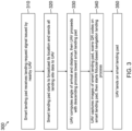
- FIG 3 is a flow diagram for a method 300 of using a marker based smart landing pad, such as those described above.
- a smart landing pad placed at a given location, receives a landing request signal issued by a nearby UAV (block 310).
- the smart landing pad then starts to broadcast its location and send all landing site data to the UAV (block 320).
- the UAV computes the angle of arrival and distance to the smart landing pad, based on the received landing site location and data, and the UAV then proceeds with the descending process toward the smart landing pad (block 330).
- the UAV captures images of the smart landing pad, scans QR codes shown on the display surface of the smart landing pad, and then starts a fiducial-based navigation landing process (block 340).
- the UAV then lands on the smart landing pad (block 350).
- a computer or processor used in the present systems and methods can be implemented using software, firmware, hardware, or any appropriate combination thereof, as known to one of skill in the art. These may be supplemented by, or incorporated in, specially-designed application-specific integrated circuits (ASICs) or field programmable gate arrays (FPGAs).
- ASICs application-specific integrated circuits
- FPGAs field programmable gate arrays
- the computer or processor can also include functions with software programs, firmware, or other computer readable instructions for carrying out various process tasks, calculations, and control functions used in the present systems and methods.
- the present methods can be implemented by computer executable instructions, such as program modules or components, which are executed by at least one processor.
- program modules include routines, programs, objects, data components, data structures, algorithms, and the like, which perform particular tasks or implement particular abstract data types.
- Instructions for carrying out the various process tasks, calculations, and generation of other data used in the operation of the methods described herein can be implemented in software, firmware, or other computer- or processor-readable instructions. These instructions are typically stored on any appropriate computer program product that includes a computer readable medium used for storage of computer readable instructions or data structures. Such a computer readable medium can be any available media that can be accessed by a general purpose or special purpose computer or processor, or any programmable logic device.
- Suitable processor-readable media may include storage or memory media such as magnetic or optical media.
- storage or memory media may include conventional hard disks, compact discs, DVDs, Blu-ray discs, or other optical storage media; volatile or nonvolatile media such as Random Access Memory (RAM); Read Only Memory (ROM), Electrically Erasable Programmable ROM (EEPROM), flash memory, and the like; or any other media that can be used to carry or store desired program code in the form of computer executable instructions or data structures.
- RAM Random Access Memory
- ROM Read Only Memory
- EEPROM Electrically Erasable Programmable ROM
- flash memory and the like
- any other media that can be used to carry or store desired program code in the form of computer executable instructions or data structures.
Landscapes
- Engineering & Computer Science (AREA)
- Aviation & Aerospace Engineering (AREA)
- Physics & Mathematics (AREA)
- Mechanical Engineering (AREA)
- General Physics & Mathematics (AREA)
- Remote Sensing (AREA)
- Acoustics & Sound (AREA)
- Radar, Positioning & Navigation (AREA)
- Automation & Control Theory (AREA)
- User Interface Of Digital Computer (AREA)
- Control Of Position, Course, Altitude, Or Attitude Of Moving Bodies (AREA)
Claims (10)
- Intelligenter Landeplatz (100), umfassend:eine flexible Anzeige (110), beinhaltend eine Anzeigeoberfläche (111), die dazu konfiguriert ist, ein oder mehrere Bilder oder Muster zu zeigen;eine Schutzschicht (112) über der Anzeigeoberfläche, wobei die Schutzschicht dazu konfiguriert ist, es einem unbemannten Fluggerät (Drohne) (240) zu ermöglichen, auf dem intelligenten Landeplatz zu landen, ohne die flexible Anzeige zu beschädigen;eine oder mehrere Ortungs- und Entfernungsmessvorrichtungen (234, 236), die operativ mit der flexiblen Anzeige gekoppelt sind und dazu dienen, mit der Drohne zu kommunizieren, so dass die flexible Anzeige basierend auf einem dreidimensionalen, während eines Sinkflugs an die Drohne kommunizierten Standort selbstortbar ist; undeine oder mehrere Kommunikationsvorrichtungen (230, 232), die operativ mit der flexiblen Anzeige gekoppelt sind und der drahtlosen Kommunikation mit einer Computer- oder mobilen Rechenvorrichtung (250, 252) dienen, die dazu dient, bei Bedarf Nutzerfunktionen bereitzustellen, die es ermöglichen, das eine oder die mehreren Bilder oder Muster, die auf der Anzeigeoberfläche gezeigt werden, in Echtzeit dynamisch zu ändern oder anzupassen;wobei das eine oder die mehreren Bilder oder Muster Folgendes umfassen:einen Hintergrundbereich (114), der konfigurierbar ist, um veränderbare Bilder anzuzeigen, die mit einer Umgebung übereinstimmen, in welcher der intelligente Landeplatz zur Verwendung als Landestelle für die Drohne platziert wird;einen Ziellandebereich (116), der von dem Hintergrundbereich umgeben wird, wobei der Ziellandebereich Folgendes beinhaltet:einen veränderbaren, unempfindlichen (118) Kontrastbereich, der es ermöglicht, dass der Ziellandebereich von der Drohne aus bei hellem Licht, in der Dunkelheit bei Nacht, oder aufgrund schlechter Sicht durch Schlechtwetter oder staubige Umgebungsbedingungen besser erkennbar ist; undeinen oder mehrere veränderbare Markierungsmusterabschnitte (120) mit veränderbaren Farben und/oder Formen, die eine Erleichterung der Mustererkennung von der Drohne aus bereitstellen; undeinen oder mehrere veränderbare Quick-Response- (QR-) Codes (122) auf dem Ziellandebereich, wobei der eine oder die mehreren QR-Codes als Referenzpunkte oder zur Kommunikation dienen;wobei die flexible Anzeige Internet-of-Things-(loT)-fähig ist, so dass auf Daten von dem intelligenten Landeplatz remote über eine Cloud zugegriffen werden kann, wodurch ermöglicht wird, dass die Daten verändert, protokolliert oder verarbeitet werden.
- Intelligenter Landeplatz (100) nach Anspruch 1, wobei die flexible Anzeige (110) rollbar, anpassbar, faltbar oder formbar ist.
- Intelligenter Landeplatz (100) nach Anspruch 1, wobei die flexible Anzeige (110) eine flexible organische Flüssigkristall-(OLCD)-Anzeige oder eine flexible organische Leuchtdioden-(OLED)-Anzeige umfasst.
- Intelligenter Landeplatz (100) nach Anspruch 1, wobei die Schutzschicht (112) ein beschichtetes hartes Material umfasst.
- Intelligenter Landeplatz (100) nach Anspruch 1, wobei die eine oder mehreren Ortungs- und Entfernungsmessvorrichtungen in der flexiblen Anzeige eingegliedert sind und Folgendes umfassen:eine globale Navigationssatellitensystem-(GNSS)-Vorrichtung (234), die dazu dient, Längen-/Breiten-/Höhen-(LLA)-Daten für die flexible Anzeige bereitzustellen, wenn sie an einer Landestelle platziert wird;einen Laserentfernungsmesser (236), der dazu dient, während eines Sinkflugs der Drohne in Richtung der Landestelle die Nähe der Drohne in Bezug auf die flexible Anzeige zu erkennen; undeine Langstrecken-(LoRa)-Kommunikations- und Navigationsvorrichtung (238), die in der flexiblen Anzeige eingegliedert ist und dazu dient, Entfernungsmessungen bereitzustellen, um während eines Sinkflugs der Drohne in Richtung der Landestelle eine Nähe und Höhe von der Drohne zur flexiblen Anzeige zu bestimmen.
- Intelligenter Landeplatz (100) nach Anspruch 1, wobei die eine oder mehreren Kommunikationsvorrichtungen (232, 239) in der flexiblen Anzeige (110) eingegliedert sind und Folgendes umfassen:eine Kurzstreckenvorrichtung (230), die dazu konfiguriert ist, eine WiFi-Verbindung oder eine Bluetooth-Verbindung bereitzustellen; undeine Cloudverbindungsvorrichtung (232), die dazu konfiguriert ist, eine Long-Term-Evolution-(LTE)-Cloudverbindung bereitzustellen.
- Verfahren (300), umfassend:Platzieren des intelligenten Landeplatzes (100) nach Anspruch 1 an einer Position der Landestelle für ein unbemanntes Fluggerät (Drohne) (240);Empfangen, an dem intelligenten Landeplatz, eines von der Drohne ausgegebenen Landeanfragesignals;Übertragen der Position und der Daten der Landestelle von dem intelligenten Landeplatz an die Drohne;Berechnen, in der Drohne, eines Ankunftswinkels und eines Abstands von dem intelligenten Landeplatz basierend auf der Position und den Daten der Landestelle; undInitiieren eines Sinkflugvorgangs der Drohne in Richtung des intelligenten Landeplatzes, während dessen die Drohne Bilder des intelligenten Landeplatzes aufnimmt, auf der Anzeigeoberfläche gezeigte Quick-Response-(QR)-Codes (122) scannt und einen Landeprozess der referenzbasierten Navigation zum Landen der Drohne auf dem intelligenten Landeplatz beginnt.
- Verfahren (300) nach Anspruch 7, wobei die Drohne eine Sensornutzlast (242) beinhaltet, die dazu konfiguriert ist, es der Drohne (240) zu ermöglichen, den intelligenten Landeplatz (100) zu tracken und mit ihm zu kommunizieren.
- Verfahren (300) nach Anspruch 8, wobei die Sensornutzlast (242) eine/s oder mehrere der Folgenden umfasst: eine Bildaufnahmevorrichtung, einen Laserentfernungssensor, einen Näherungssensor oder eine Langstrecken-(LoRa)- und Flugzeit-(ToF)-Entfernungserfassungsvorrichtung.
- Verfahren (300) nach Anspruch 7, wobei ein eigener Datenkommunikationskanal (239) die Position der Landestelle und Daten von dem intelligenten Landeplatz (100) an die Drohne (240) überträgt.
Applications Claiming Priority (2)
| Application Number | Priority Date | Filing Date | Title |
|---|---|---|---|
| IN202111004297 | 2021-02-01 | ||
| US17/212,685 US11685558B2 (en) | 2021-02-01 | 2021-03-25 | Marker based smart landing pad |
Publications (2)
| Publication Number | Publication Date |
|---|---|
| EP4036017A1 EP4036017A1 (de) | 2022-08-03 |
| EP4036017B1 true EP4036017B1 (de) | 2024-12-11 |
Family
ID=79316816
Family Applications (1)
| Application Number | Title | Priority Date | Filing Date |
|---|---|---|---|
| EP22151188.4A Active EP4036017B1 (de) | 2021-02-01 | 2022-01-12 | Marker-basierter intelligenter landeplatz |
Country Status (1)
| Country | Link |
|---|---|
| EP (1) | EP4036017B1 (de) |
Family Cites Families (7)
| Publication number | Priority date | Publication date | Assignee | Title |
|---|---|---|---|---|
| US20160122038A1 (en) * | 2014-02-25 | 2016-05-05 | Singularity University | Optically assisted landing of autonomous unmanned aircraft |
| US20170015438A1 (en) * | 2014-07-19 | 2017-01-19 | Jonathan Matthew Harding | Wireless portable landing zone |
| WO2016196093A1 (en) * | 2015-06-01 | 2016-12-08 | Stoman Nicolaas | Systems, methods, and apparatuses for managing aerial drone parcel transfers |
| US10395544B1 (en) * | 2016-08-29 | 2019-08-27 | Amazon Technologies, Inc. | Electronic landing marker |
| US20180265196A1 (en) * | 2017-03-17 | 2018-09-20 | Frank Andrew Phillips | Quick-Deploying Portable Unmanned Aerial System (UAS)/ Unmanned Aerial Vehicle (UAV) Landing Pad |
| CN106910431A (zh) * | 2017-05-04 | 2017-06-30 | 京东方科技集团股份有限公司 | 柔性显示屏及改变柔性显示屏的形状的方法 |
| US10713958B2 (en) * | 2017-06-13 | 2020-07-14 | Benchmark Electronics, Inc. | Automated landing solution systems and methods |
-
2022
- 2022-01-12 EP EP22151188.4A patent/EP4036017B1/de active Active
Also Published As
| Publication number | Publication date |
|---|---|
| EP4036017A1 (de) | 2022-08-03 |
Similar Documents
| Publication | Publication Date | Title |
|---|---|---|
| US11685558B2 (en) | Marker based smart landing pad | |
| US12007761B2 (en) | Unmanned aerial vehicle inspection system | |
| AU2021202509B2 (en) | Image based localization for unmanned aerial vehicles, and associated systems and methods | |
| US12276501B2 (en) | Control point identification and reuse system | |
| US9513635B1 (en) | Unmanned aerial vehicle inspection system | |
| US10778967B2 (en) | Systems and methods for improving performance of a robotic vehicle by managing on-board camera defects | |
| EP2118713B1 (de) | Präzisionsnäherungssteuerung | |
| WO2019040804A1 (en) | SYSTEMS AND METHODS FOR ENHANCING THE PERFORMANCE OF A ROBOTIC VEHICLE BY MANAGING ON-BOARD CAMERA OBSTRUCTIONS | |
| US11828859B2 (en) | Navigation using self-describing fiducials | |
| KR102025687B1 (ko) | 듀얼 gps를 이용한 자율 비행 시스템 및 방법 | |
| US11440657B2 (en) | Aerial vehicles with machine vision | |
| US12299925B2 (en) | Method and system for locating a light source | |
| KR20140030610A (ko) | 지상 감시장비와 연동된 무인기를 이용한 감시 방법 | |
| JP2020149640A (ja) | 飛行システム及び着陸制御方法 | |
| KR20190048688A (ko) | 드론을 이용한 자율 비행 시스템 및 방법 | |
| EP4036017A1 (de) | Marker-basierter intelligenter landeplatz | |
| US20180319511A1 (en) | Systems for and methods of providing indicators useful for piloting an aircraft | |
| CA3165323C (en) | Method and system for locating a light source | |
| KR102794713B1 (ko) | 드론탐지타겟의 gps 좌표 계산 방법 및 그 장치 |
Legal Events
| Date | Code | Title | Description |
|---|---|---|---|
| PUAI | Public reference made under article 153(3) epc to a published international application that has entered the european phase |
Free format text: ORIGINAL CODE: 0009012 |
|
| STAA | Information on the status of an ep patent application or granted ep patent |
Free format text: STATUS: THE APPLICATION HAS BEEN PUBLISHED |
|
| AK | Designated contracting states |
Kind code of ref document: A1 Designated state(s): AL AT BE BG CH CY CZ DE DK EE ES FI FR GB GR HR HU IE IS IT LI LT LU LV MC MK MT NL NO PL PT RO RS SE SI SK SM TR |
|
| STAA | Information on the status of an ep patent application or granted ep patent |
Free format text: STATUS: REQUEST FOR EXAMINATION WAS MADE |
|
| 17P | Request for examination filed |
Effective date: 20220927 |
|
| RBV | Designated contracting states (corrected) |
Designated state(s): AL AT BE BG CH CY CZ DE DK EE ES FI FR GB GR HR HU IE IS IT LI LT LU LV MC MK MT NL NO PL PT RO RS SE SI SK SM TR |
|
| P01 | Opt-out of the competence of the unified patent court (upc) registered |
Effective date: 20230421 |
|
| STAA | Information on the status of an ep patent application or granted ep patent |
Free format text: STATUS: EXAMINATION IS IN PROGRESS |
|
| 17Q | First examination report despatched |
Effective date: 20230810 |
|
| REG | Reference to a national code |
Ref country code: DE Ref legal event code: R079 Ref document number: 602022008494 Country of ref document: DE Free format text: PREVIOUS MAIN CLASS: B64F0001360000 Ipc: G05D0001000000 |
|
| GRAP | Despatch of communication of intention to grant a patent |
Free format text: ORIGINAL CODE: EPIDOSNIGR1 |
|
| STAA | Information on the status of an ep patent application or granted ep patent |
Free format text: STATUS: GRANT OF PATENT IS INTENDED |
|
| RIC1 | Information provided on ipc code assigned before grant |
Ipc: G08G 5/00 20060101ALI20240624BHEP Ipc: B64U 70/97 20230101ALI20240624BHEP Ipc: G08G 5/02 20060101ALI20240624BHEP Ipc: G05D 1/00 20060101AFI20240624BHEP |
|
| INTG | Intention to grant announced |
Effective date: 20240709 |
|
| GRAS | Grant fee paid |
Free format text: ORIGINAL CODE: EPIDOSNIGR3 |
|
| GRAA | (expected) grant |
Free format text: ORIGINAL CODE: 0009210 |
|
| STAA | Information on the status of an ep patent application or granted ep patent |
Free format text: STATUS: THE PATENT HAS BEEN GRANTED |
|
| AK | Designated contracting states |
Kind code of ref document: B1 Designated state(s): AL AT BE BG CH CY CZ DE DK EE ES FI FR GB GR HR HU IE IS IT LI LT LU LV MC MK MT NL NO PL PT RO RS SE SI SK SM TR |
|
| REG | Reference to a national code |
Ref country code: GB Ref legal event code: FG4D |
|
| REG | Reference to a national code |
Ref country code: CH Ref legal event code: EP |
|
| REG | Reference to a national code |
Ref country code: DE Ref legal event code: R096 Ref document number: 602022008494 Country of ref document: DE |
|
| REG | Reference to a national code |
Ref country code: IE Ref legal event code: FG4D |
|
| REG | Reference to a national code |
Ref country code: LT Ref legal event code: MG9D |
|
| PG25 | Lapsed in a contracting state [announced via postgrant information from national office to epo] |
Ref country code: HR Free format text: LAPSE BECAUSE OF FAILURE TO SUBMIT A TRANSLATION OF THE DESCRIPTION OR TO PAY THE FEE WITHIN THE PRESCRIBED TIME-LIMIT Effective date: 20241211 |
|
| PG25 | Lapsed in a contracting state [announced via postgrant information from national office to epo] |
Ref country code: FI Free format text: LAPSE BECAUSE OF FAILURE TO SUBMIT A TRANSLATION OF THE DESCRIPTION OR TO PAY THE FEE WITHIN THE PRESCRIBED TIME-LIMIT Effective date: 20241211 |
|
| PG25 | Lapsed in a contracting state [announced via postgrant information from national office to epo] |
Ref country code: BG Free format text: LAPSE BECAUSE OF FAILURE TO SUBMIT A TRANSLATION OF THE DESCRIPTION OR TO PAY THE FEE WITHIN THE PRESCRIBED TIME-LIMIT Effective date: 20241211 |
|
| REG | Reference to a national code |
Ref country code: NL Ref legal event code: MP Effective date: 20241211 |
|
| PG25 | Lapsed in a contracting state [announced via postgrant information from national office to epo] |
Ref country code: ES Free format text: LAPSE BECAUSE OF FAILURE TO SUBMIT A TRANSLATION OF THE DESCRIPTION OR TO PAY THE FEE WITHIN THE PRESCRIBED TIME-LIMIT Effective date: 20241211 |
|
| PG25 | Lapsed in a contracting state [announced via postgrant information from national office to epo] |
Ref country code: NO Free format text: LAPSE BECAUSE OF FAILURE TO SUBMIT A TRANSLATION OF THE DESCRIPTION OR TO PAY THE FEE WITHIN THE PRESCRIBED TIME-LIMIT Effective date: 20250311 |
|
| PG25 | Lapsed in a contracting state [announced via postgrant information from national office to epo] |
Ref country code: LV Free format text: LAPSE BECAUSE OF FAILURE TO SUBMIT A TRANSLATION OF THE DESCRIPTION OR TO PAY THE FEE WITHIN THE PRESCRIBED TIME-LIMIT Effective date: 20241211 Ref country code: GR Free format text: LAPSE BECAUSE OF FAILURE TO SUBMIT A TRANSLATION OF THE DESCRIPTION OR TO PAY THE FEE WITHIN THE PRESCRIBED TIME-LIMIT Effective date: 20250312 |
|
| PG25 | Lapsed in a contracting state [announced via postgrant information from national office to epo] |
Ref country code: RS Free format text: LAPSE BECAUSE OF FAILURE TO SUBMIT A TRANSLATION OF THE DESCRIPTION OR TO PAY THE FEE WITHIN THE PRESCRIBED TIME-LIMIT Effective date: 20250311 |
|
| PG25 | Lapsed in a contracting state [announced via postgrant information from national office to epo] |
Ref country code: NL Free format text: LAPSE BECAUSE OF FAILURE TO SUBMIT A TRANSLATION OF THE DESCRIPTION OR TO PAY THE FEE WITHIN THE PRESCRIBED TIME-LIMIT Effective date: 20241211 |
|
| REG | Reference to a national code |
Ref country code: AT Ref legal event code: MK05 Ref document number: 1750894 Country of ref document: AT Kind code of ref document: T Effective date: 20241211 |
|
| PG25 | Lapsed in a contracting state [announced via postgrant information from national office to epo] |
Ref country code: SM Free format text: LAPSE BECAUSE OF FAILURE TO SUBMIT A TRANSLATION OF THE DESCRIPTION OR TO PAY THE FEE WITHIN THE PRESCRIBED TIME-LIMIT Effective date: 20241211 |
|
| PG25 | Lapsed in a contracting state [announced via postgrant information from national office to epo] |
Ref country code: PL Free format text: LAPSE BECAUSE OF FAILURE TO SUBMIT A TRANSLATION OF THE DESCRIPTION OR TO PAY THE FEE WITHIN THE PRESCRIBED TIME-LIMIT Effective date: 20241211 |
|
| PG25 | Lapsed in a contracting state [announced via postgrant information from national office to epo] |
Ref country code: IS Free format text: LAPSE BECAUSE OF FAILURE TO SUBMIT A TRANSLATION OF THE DESCRIPTION OR TO PAY THE FEE WITHIN THE PRESCRIBED TIME-LIMIT Effective date: 20250411 |
|
| PG25 | Lapsed in a contracting state [announced via postgrant information from national office to epo] |
Ref country code: PT Free format text: LAPSE BECAUSE OF FAILURE TO SUBMIT A TRANSLATION OF THE DESCRIPTION OR TO PAY THE FEE WITHIN THE PRESCRIBED TIME-LIMIT Effective date: 20250411 |
|
| PG25 | Lapsed in a contracting state [announced via postgrant information from national office to epo] |
Ref country code: EE Free format text: LAPSE BECAUSE OF FAILURE TO SUBMIT A TRANSLATION OF THE DESCRIPTION OR TO PAY THE FEE WITHIN THE PRESCRIBED TIME-LIMIT Effective date: 20241211 |
|
| PG25 | Lapsed in a contracting state [announced via postgrant information from national office to epo] |
Ref country code: RO Free format text: LAPSE BECAUSE OF FAILURE TO SUBMIT A TRANSLATION OF THE DESCRIPTION OR TO PAY THE FEE WITHIN THE PRESCRIBED TIME-LIMIT Effective date: 20241211 Ref country code: AT Free format text: LAPSE BECAUSE OF FAILURE TO SUBMIT A TRANSLATION OF THE DESCRIPTION OR TO PAY THE FEE WITHIN THE PRESCRIBED TIME-LIMIT Effective date: 20241211 |
|
| PG25 | Lapsed in a contracting state [announced via postgrant information from national office to epo] |
Ref country code: SK Free format text: LAPSE BECAUSE OF FAILURE TO SUBMIT A TRANSLATION OF THE DESCRIPTION OR TO PAY THE FEE WITHIN THE PRESCRIBED TIME-LIMIT Effective date: 20241211 |
|
| PG25 | Lapsed in a contracting state [announced via postgrant information from national office to epo] |
Ref country code: CZ Free format text: LAPSE BECAUSE OF FAILURE TO SUBMIT A TRANSLATION OF THE DESCRIPTION OR TO PAY THE FEE WITHIN THE PRESCRIBED TIME-LIMIT Effective date: 20241211 |
|
| PG25 | Lapsed in a contracting state [announced via postgrant information from national office to epo] |
Ref country code: IT Free format text: LAPSE BECAUSE OF FAILURE TO SUBMIT A TRANSLATION OF THE DESCRIPTION OR TO PAY THE FEE WITHIN THE PRESCRIBED TIME-LIMIT Effective date: 20241211 |
|
| REG | Reference to a national code |
Ref country code: CH Ref legal event code: PL |
|
| PG25 | Lapsed in a contracting state [announced via postgrant information from national office to epo] |
Ref country code: SE Free format text: LAPSE BECAUSE OF FAILURE TO SUBMIT A TRANSLATION OF THE DESCRIPTION OR TO PAY THE FEE WITHIN THE PRESCRIBED TIME-LIMIT Effective date: 20241211 |
|
| REG | Reference to a national code |
Ref country code: DE Ref legal event code: R097 Ref document number: 602022008494 Country of ref document: DE |
|
| PG25 | Lapsed in a contracting state [announced via postgrant information from national office to epo] |
Ref country code: LU Free format text: LAPSE BECAUSE OF NON-PAYMENT OF DUE FEES Effective date: 20250112 Ref country code: MC Free format text: LAPSE BECAUSE OF FAILURE TO SUBMIT A TRANSLATION OF THE DESCRIPTION OR TO PAY THE FEE WITHIN THE PRESCRIBED TIME-LIMIT Effective date: 20241211 |
|
| PG25 | Lapsed in a contracting state [announced via postgrant information from national office to epo] |
Ref country code: DK Free format text: LAPSE BECAUSE OF FAILURE TO SUBMIT A TRANSLATION OF THE DESCRIPTION OR TO PAY THE FEE WITHIN THE PRESCRIBED TIME-LIMIT Effective date: 20241211 |
|
| PG25 | Lapsed in a contracting state [announced via postgrant information from national office to epo] |
Ref country code: BE Free format text: LAPSE BECAUSE OF NON-PAYMENT OF DUE FEES Effective date: 20250131 |
|
| PLBE | No opposition filed within time limit |
Free format text: ORIGINAL CODE: 0009261 |
|
| STAA | Information on the status of an ep patent application or granted ep patent |
Free format text: STATUS: NO OPPOSITION FILED WITHIN TIME LIMIT |
|
| PG25 | Lapsed in a contracting state [announced via postgrant information from national office to epo] |
Ref country code: CH Free format text: LAPSE BECAUSE OF NON-PAYMENT OF DUE FEES Effective date: 20250131 |
|
| REG | Reference to a national code |
Ref country code: BE Ref legal event code: MM Effective date: 20250131 |
|
| 26N | No opposition filed |
Effective date: 20250912 |
|
| PG25 | Lapsed in a contracting state [announced via postgrant information from national office to epo] |
Ref country code: IE Free format text: LAPSE BECAUSE OF NON-PAYMENT OF DUE FEES Effective date: 20250112 |
|
| PGFP | Annual fee paid to national office [announced via postgrant information from national office to epo] |
Ref country code: DE Payment date: 20260127 Year of fee payment: 5 |
|
| PGFP | Annual fee paid to national office [announced via postgrant information from national office to epo] |
Ref country code: FR Payment date: 20260127 Year of fee payment: 5 |