EP4035983A2 - Bicycle trailer with variable transport volume - Google Patents
Bicycle trailer with variable transport volume Download PDFInfo
- Publication number
- EP4035983A2 EP4035983A2 EP22154219.4A EP22154219A EP4035983A2 EP 4035983 A2 EP4035983 A2 EP 4035983A2 EP 22154219 A EP22154219 A EP 22154219A EP 4035983 A2 EP4035983 A2 EP 4035983A2
- Authority
- EP
- European Patent Office
- Prior art keywords
- bracket
- forehead
- connector
- forehead bracket
- sleeve
- Prior art date
- Legal status (The legal status is an assumption and is not a legal conclusion. Google has not performed a legal analysis and makes no representation as to the accuracy of the status listed.)
- Granted
Links
- 210000001061 forehead Anatomy 0.000 claims abstract description 103
- 230000006835 compression Effects 0.000 claims description 26
- 238000007906 compression Methods 0.000 claims description 26
- 238000007598 dipping method Methods 0.000 claims 1
- 230000000712 assembly Effects 0.000 description 2
- 238000000429 assembly Methods 0.000 description 2
- 238000005516 engineering process Methods 0.000 description 2
- 238000003698 laser cutting Methods 0.000 description 2
- 238000004519 manufacturing process Methods 0.000 description 2
- 229910052751 metal Inorganic materials 0.000 description 2
- 239000002184 metal Substances 0.000 description 2
- 229910000831 Steel Inorganic materials 0.000 description 1
- 239000004411 aluminium Substances 0.000 description 1
- 229910052782 aluminium Inorganic materials 0.000 description 1
- XAGFODPZIPBFFR-UHFFFAOYSA-N aluminium Chemical compound [Al] XAGFODPZIPBFFR-UHFFFAOYSA-N 0.000 description 1
- 230000007613 environmental effect Effects 0.000 description 1
- 230000003203 everyday effect Effects 0.000 description 1
- 239000000446 fuel Substances 0.000 description 1
- 239000000463 material Substances 0.000 description 1
- 238000004080 punching Methods 0.000 description 1
- 229910001220 stainless steel Inorganic materials 0.000 description 1
- 239000010935 stainless steel Substances 0.000 description 1
- 239000010959 steel Substances 0.000 description 1
Images


Classifications
-
- B—PERFORMING OPERATIONS; TRANSPORTING
- B62—LAND VEHICLES FOR TRAVELLING OTHERWISE THAN ON RAILS
- B62K—CYCLES; CYCLE FRAMES; CYCLE STEERING DEVICES; RIDER-OPERATED TERMINAL CONTROLS SPECIALLY ADAPTED FOR CYCLES; CYCLE AXLE SUSPENSIONS; CYCLE SIDE-CARS, FORECARS, OR THE LIKE
- B62K27/00—Sidecars; Forecars; Trailers or the like specially adapted to be attached to cycles
- B62K27/003—Trailers
-
- B—PERFORMING OPERATIONS; TRANSPORTING
- B62—LAND VEHICLES FOR TRAVELLING OTHERWISE THAN ON RAILS
- B62K—CYCLES; CYCLE FRAMES; CYCLE STEERING DEVICES; RIDER-OPERATED TERMINAL CONTROLS SPECIALLY ADAPTED FOR CYCLES; CYCLE AXLE SUSPENSIONS; CYCLE SIDE-CARS, FORECARS, OR THE LIKE
- B62K27/00—Sidecars; Forecars; Trailers or the like specially adapted to be attached to cycles
- B62K27/02—Frames
Definitions
- bicycle trailers are often used, which usually have two wheels and are connected to the bicycle in such a way that the trailer can be towed with the bicycle.
- the advent of e-bikes in particular has made it easier to transport goods with the help of a bicycle trailer, since larger loads can also be transported without excessive effort.
- the invention is based on the object of providing a bicycle trailer whose loading volume is variable and can be easily and quickly adapted to current needs without tools, even with gloves.
- a joint for the rotatable mounting of a headband or a side wall of a bicycle trailer comprising a connector with two legs spaced apart from one another, a bearing sleeve and a fixing device, the fixing device enabling the positive locking of the headband relative to the connector in allows at least two positions, wherein the forehead bracket is rotatably mounted on the connector by means of the bearing sleeve, and wherein a clear width between the legs is greater than a diameter of the forehead bracket, so that the forehead bracket can be displaced on the bearing sleeve between the legs.
- the front bracket/tail lift can be moved on the bearing sleeve if necessary, so that a form fit between the front bracket and the connector is eliminated. Then the forehead bracket can be pivoted into another position with the bearing sleeve as the axis of rotation. The forehead bar can then be adjusted in this position by moving the forehead bar in be locked again in a form-fitting manner in the opposite direction.
- the forehead bracket is also the gripping element for the hand of an operator, no tools are required to release or engage the form fit between the forehead bracket and connector.
- This operation can also be carried out without problems in inhospitable environmental conditions (low outside temperature, rain and/or darkness) and with gloves. Repositioning the browband in a different position takes only a few seconds. Therefore, the user of the bicycle trailer makes frequent use of it and the load to be transported with the bicycle trailer is optimally accommodated in the bicycle trailer.
- the length of the trailer can be shortened so that the trailer is only as long as necessary. This is an advantage not only when driving, but also when parked.
- the connector and the joint are easy to produce in terms of manufacturing technology.
- the connector itself can be made from sheet metal produced by stamping or laser cutting by folding it twice.
- a suitable material high-strength aluminium, steel, stainless steel, ...) in connection with a suitable dimensioning, the joint is very robust, so that it can withstand tough everyday use for many years without complaint.
- the form-fitting connection or locking of the forehead bracket relative to the connector can be achieved in that a plurality of pins are fixedly arranged on the connector, these pins protruding into the space between the legs, that there is a bore in the forehead bracket, and that the form-fitting locking of the forehead bar is established, by one of the pins going into the bore of the forehead bracket when the forehead bracket is moved on the bearing sleeve.
- spring means are provided in the joint, the spring force of which presses the forehead bracket on the bearing sleeve in the direction of the leg on which the pins are fastened or in which the bores are formed.
- These spring means can be designed in a wide variety of ways. It is thus possible, for example, for the spring means to comprise a compression spring, a spring guide and a sliding sleeve, and for the compression spring to be supported at one end against the spring guide and at the other end against the sliding sleeve. It is preferred if the spring guide is accommodated in the forehead bracket and the sliding sleeve is supported against a leg of the connector. This is the leg of the connector that is positioned opposite the leg with the pins or holes.
- the compression spring it is also possible for the compression spring to be supported with one end against the sleeve and with the other end against the sliding sleeve.
- a headband with two identical joints according to the invention will be attached to the bicycle trailer. This increases the resilience of the fixation, offers redundancy and reduces the number of assemblies.
- the other joint can be designed as a completely normal joint without a fixing device.
- this joint also needs a have an axial degree of freedom, so that the forehead bracket is displaceable in the axial direction, ie parallel to the axis of rotation of the bearing sleeve.
- joints according to the invention are arranged on both longitudinal beams of the bicycle trailer, and two such joints store a forehead bracket and in one of the user of the bicycle trailer lock the desired position in a form-fitting manner.
- a front bar that can be locked according to the invention or a lockable drop side will also be provided both at the front end and at the rear end of the loading area of the bicycle trailer. This prevents the bike trailer load from sliding forwards or backwards off the loading area. At the same time, securing the load on the loading area of the bicycle trailer is simplified.
- the forehead bracket can be designed as a U-shaped pipe bend with a circular cross-section or else a square cross-section. However, it is also possible to attach a side wall to the front bar so that small objects cannot slip off the loading area under the tube bar.
- the drawbar can be attached to the actual bicycle trailer in two or more different positions. If short loads are to be transported with the bicycle trailer, the drawbar is mounted in such a way that it has a short effective length. This reduces the length of the bicycle trailer and makes it easier to drive in downtown areas or on cycle paths. If long items of cargo are to be transported, the drawbar is pulled out of the trailer as required.
- an advantage of the trailer for bicycles according to the invention is its dimensional variability; especially in length, so that the trailer can be shortened to transport loads with smaller dimensions, so that driving agility is maintained. To transport larger loads, the trailer can be extended to ensure safe transport.
- FIGS. 1 and 2 show the trailer according to the invention in the unfolded, long mode of use (FIG. 1) and once in the folded, short mode of use (FIG. 2).
- the trailer for bicycles 1 consists of the base support 12 shown in FIG. 3, which in turn consists of the two longitudinal supports 2, the floor panel 3, and the connector 4 is possible as a stamped and bent part. Laser cutting instead of punching is also possible.
- connection of the longitudinal members 2, which are shown here, for example, in a cylindrical shape (tube), with the connector 4 takes place, for example, with the aid of the at least one screw 13, which is screwed through the bores 15 of the connector 4 shown in Figure 4, and through the bores 26 of the longitudinal member 2 shown in FIG. 5 are joined.
- the screws 13 are screwed to the nuts 17.
- the connector can also be provided with a corresponding thread.
- connection between the connectors 4 and the side members 2 can also be effected, for example, by riveting or in some other suitable manner.
- the longitudinal beams 2 are arranged in such a way that they lie between the two legs 22 of the U-shaped connector 4 .
- connection of the floor panel 3, which in a first embodiment variant, as shown in Figure 5, is designed, for example, as a sheet metal bent on the front side, with the side member 2 is carried out, for example, with the aid of the screws 14, which pass through the bores 23 and 24 of the side member 2, as well as through the holes 25 of the floor panel shown in FIG 3 are joined, the screws 14 being screwed to a nut, not shown.
- the connection between the side member 2 and the floor panel 3 can also be effected, for example, by riveting or in some other suitable manner.
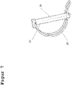
- the side brackets 6 shown in Figures 1 and 2, which are shown here for example with a circular cross section, are connected to the connectors 4 with the aid of a linch pin 27 shown in Figure 7, which consist of the pin 28 and the bracket spring 29, the bracket spring 29 is suitably connected to the pin 28 in such a way that the clip spring 29 can be rotated relative to the pin 28, and that the clip spring 29 assumes the position shown in Figure 7 relative to the pin 28 when no twisting force is exerted on the clip spring 29 .
- Linchpins in general are state of the art and are therefore not described in detail here.
- the bracket spring 29 is twisted in such a way that the pin 28 of the linch pin 28 is guided through the bore 17 in the carrier 4 and through the bore 30 in the side bracket 6 shown in Figure 8, with the side brackets 6 being positioned in such a way are arranged to lie between the two legs 22 of the connectors 4.
- the use of the linch pins 27 is primarily used for quick assembly and disassembly of the side brackets, it being possible for the side brackets 6 to be connected to the connectors 4 by screwing or riveting, for example.
- the trailer for bicycles 1 according to the invention has the drawbar 8 shown in FIGS. 1 and 2, which can be connected to the base support 12 in a detachable manner and in a number of positions.
- the drawbar 8 connects the trailer 1 according to the invention with the towing vehicle, in particular the bicycle.
- the trailer for bicycles 1 according to the invention also has the wheels 10 shown in FIGS.
- the axle 7 is connected to the base support 12 in a suitable manner.
- a fixing device 31 according to the invention is integrated in the connectors 4 .
- a first embodiment is explained with reference to FIGS. 10 to 13 and a second embodiment of the fixing device 31 according to the invention is explained with reference to FIGS.
- the forehead brackets 5 are connected to the connectors 4 in such a way that they can be rotated with respect to the connector 4 .
- the forehead brackets 5 are articulated on the connectors.
- the axis of rotation of this joint is formed by the bearing sleeve 42 in this exemplary embodiment.
- the forehead brackets 5 In order to be able to lock the forehead brackets 5 in different positions (see FIGS. 1 and 2), one of the fixing devices 31 explained below is provided in the connectors 4 .
- the forehead brackets 5 can only be twisted/folded down between the positions shown in FIGS. 1 and 2 if the fixation is released.
- Figure 10 shows a first embodiment of the fixing device 31 whose function is that To fix the forehead bracket 5 in the end positions shown in Figures 1 and 2.
- the forehead bracket 5 is connected to the connectors 4 via the bearing sleeve 42 in such a way that the forehead bracket 5 can rotate about the longitudinal axis of the bearing sleeve 42, with the bearing sleeve 42 protruding through the bore 18 of the connector 4 and through the bore 38 of the forehead bracket 5 . It can be secured, for example, with the screw 33 ( Figure 11).
- the bearing sleeve 42 can also be secured with the aid of a retaining ring.
- a rotatable connection of the forehead brackets 5 to the connectors 4 in another suitable manner, for example by riveting, is also conceivable.
- the end brackets 5 are arranged in such a way that they lie between the two legs 22 of the connector 4 . It is clear from FIGS. 11 and 12 that the clear width between the legs 22 is greater than the outside diameter of the forehead bracket 5.
- FIGS. 11 and 12 show the fixing device 31 in the “active” position, i. G. rotating the forehead bracket 5 is not possible.
- the connectors 4 are arranged "in the same direction". This makes it possible to move the forehead bracket 5 against the force of the compression springs 35 in the direction of the arrow Y relative to the connector. Characterized the pin 34 moves out of the bore 32 of the forehead bracket 5 and the Form closure is cancelled. Then the forehead bracket 5 can be pivoted.
- FIG. 13 shows the connector 4 with the pins 34 and 39, the pin 34 serving to fix the forehead bracket 5 in the end position shown in FIG. 2 and the pin 39 for fixing the forehead bracket 5 in the end position shown in FIG.
- the pins 34 and 39 are inserted into the bores 19 and 21 of the connector 4 in such a way that they are axially fixed and project into the space formed by the legs 22 of the connector 4, as shown in FIGS.
- FIG. 10 and 11 show a first variant of the fixing device 31 in the fixed end position of the forehead bracket 5 shown in FIG.
- the bearing sleeve 42 and the pin 34 the forehead bracket 5 is fixed in position.
- the space formed by the legs 22 of the connector 4 is selected to be large enough for the forehead bracket 5 to be able to move in the direction marked Y in FIG.
- the compression spring 35 shown in FIGS. 10, 11 and 12 is guided in a spring guide 36, with one end of the compression spring 35 being supported on the bottom 40 of the spring guide 36.
- the spring guide 36 is accommodated in a hole in the forehead bracket 5 .
- the spring guide 36 in turn is supported with the collar 41 on the forehead bracket 5 .
- the opposite end of the compression spring 35 is supported on the connector 4 via the sliding sleeve 37 .
- the compression spring 35 generates a force on the forehead bracket 5 in the opposite direction to the direction marked Y in FIG. 10, so that the forehead bracket 5, as shown in FIGS. In In this position, there is a positive fit between the forehead bracket 5 and the connector 4.
- a compression spring 35 and a spring guide 36 and a sliding sleeve 37 are shown on both sides of the forehead bracket 5 .
- the forehead bracket 5 In order to unlock the forehead bracket 5, the forehead bracket 5 is displaced in the direction marked Y in FIG. The forehead bracket moves on the bearing sleeve 42 so that the pin 34 no longer protrudes into the bore 32 of the forehead bracket 5 when the travel distance is sufficiently large, as a result of which the forehead bracket 5 can be rotated on the bearing sleeve 42 .
- the forehead bracket 5 can be transferred from the end position shown in Figure 2 to the end position shown in Figure 1 by turning it on the bearing sleeve 42, with the sliding sleeve 37 reducing the friction between the compression spring 35 and the connector 4 and thus the time needed to turn the Forehead bracket 5 required force, and wear on the connector 4 and the compression spring 35 is reduced.
- the pin 39 shown in Figure 13 enters the bore 32 of the forehead bracket 5, as a result of which the forehead bracket 5 moves in the end position shown in Figure 1 is fixed.
- the force of the compression spring 35 prevents the forehead bracket 5 from being able to move independently in the direction marked Y in FIG. 10 and thus unlocks itself.
- FIG. 14 shows a second embodiment variant of the fixing device 31, the function of which is to fix the forehead brackets 5 in the end positions shown in FIGS.
- the forehead brackets 5 are connected in an articulated manner to the connectors 4 so that they can be rotated relative to the connectors 4 .
- the forehead brackets 5 can be fixed using the fixing device 31 explained below.
- the forehead brackets 5 can only be twisted relative to the connectors 4 if the fixation is released.
- the main difference from the first variant is that a sleeve 43 is guided in the forehead bracket 5, which can be displaced along the bearing sleeve 42 together with the forehead bracket 5.
- bores 21 are provided, in which the sleeve 43 engages in order to create a form fit.
- the forehead bracket 5 is connected to the connectors 4 via the bearing sleeve 42 in such a way that the forehead bracket can rotate around the bearing sleeve 42, with the bearing sleeve 42 being inserted through the bore 18 in the connectors 4 and through the bore 38 in the forehead bracket 5 and with the screw 33 is secured.
- the bearing sleeve 42 can also be secured, for example, with the aid of a securing ring.
- the end brackets 5 are arranged in such a way that they lie between the two legs 22 of the connector 4 .
- FIGS. 14, 15 and 16 show a second variant embodiment of the fixing device 31 in the fixed position shown in FIG End position of the forehead brackets 5, with the fixation taking place, as can be seen in FIGS.
- the bearing sleeve 42 and the sleeve 43 the forehead bracket 5 is fixed in its position.
- the space (clear width) formed by the legs 22 of the connector 4 is selected to be large enough for the forehead bracket 5 to be able to move in the direction indicated by the arrow "Y" in FIG.
- the compression spring 44 shown in FIGS. 14 and 15 is guided in a bore in a sleeve 43 .
- the sleeve 43 is accommodated in a hole in the forehead bracket 5 .
- One end of the compression spring 44 is supported on the bottom 46 of the sleeve 43 .
- the sleeve 43 in turn is supported with the collar 47 on the forehead bracket 5 .
- the opposite end of the compression spring 44 is supported on the connector 4 via the sliding sleeve 45 guided in the sleeve 43 .
- the compression spring 44 generates a force on the forehead bracket 5 in the opposite direction to the direction marked Y in FIG. 14, so that the forehead bracket 5, as shown in FIGS.
- a compression spring 44 and a sleeve 43 and a sliding sleeve 45 are shown on both sides of the forehead bracket 5 .
- the forehead bracket 5 In order to unlock the forehead bracket 5, the forehead bracket 5 is displaced in the direction marked Y in FIG. The forehead bracket moves on the bearing sleeve 42 so that the sleeve 43 no longer enters the bore 21 of the Connector 4 projects, as a result of which the forehead bracket 5 can be rotated on the bearing sleeve 42 .
- the forehead bracket 5 can be transferred from the end position shown in Figure 2 to the end position shown in Figure 1 by turning on the bearing sleeve 42, with the sliding sleeve 45 reducing the friction between the compression spring 44 and the connector 4 and thus the time required to turn the Forehead bracket 5 required force and wear on the connector 4 and the compression spring 44 is reduced.
- the forehead bracket is moved in the direction of the spring force, i.e. against the direction marked "Y" in Figure 14, the sleeve 43 shown in Figure 16 enters the bore 21 of the connector 4, whereby the forehead bracket 5 is fixed in the end position shown in FIG. At the same time, the force of the compression spring 44 prevents the forehead bracket 5 from being able to move independently in the direction marked "Y" in FIG. 9 and thus unlocks itself.
- Unlocking and pivoting the forehead bar 5 is very simple, requires no tools and can be easily performed even with gloves.
Abstract
Es wird ein Fahrradanhänger vorgeschlagen, dessen vorderer und hinterer Stirnbügel in verschiedenen Positionen arretierbar sind, so dass auf einfache Weise die Ladefläche des Fahrradanhängers verändert werden kann und der zu transportierenden Ladung angepasst werden kann.A bicycle trailer is proposed, the front and rear forehead brackets of which can be locked in different positions, so that the loading area of the bicycle trailer can be changed in a simple manner and can be adapted to the load to be transported.
Description
Die Reduktion des C02-Ausstoßes insbesondere im Straßenverkehr stellt eine der größten Herausforderungen der heutigen Zeit da. Diese Reduktion lässt sich zum einen durch neue Antriebskonzepte für Kraftfahrzeuge, wie beispielsweise elektrische Antriebe oder Brennstoffzellensysteme erreichen. Ein weiterer Ansatz ist die Reduzierung der mit Kraftfahrzeugen zurückgelegte Stecke indem andere Verkehrsmittel zum Einsatz kommen. Dies wären beispielsweise öffentliche Verkehrsmittel wie Bahn oder Bus. Ebenso stellt das Fahrrad, insbesondere bei kürzeren Stecken, eine Alternative zu Kraftfahrzeugen dar. Problematisch ist jedoch, dass mit Fahrräder nur eine geringe Last sowohl in Form von Gewicht als auch in Form von Volumen befördert werden kann, was den Einsatzbereich des Fahrrades erheblich einschränkt.The reduction of C0 2 emissions, especially in road traffic, is one of the greatest challenges of today. On the one hand, this reduction can be achieved through new drive concepts for motor vehicles, such as electric drives or fuel cell systems. Another approach is to reduce the distances covered by motor vehicles by using other means of transport. These would be, for example, public transport such as trains or buses. The bicycle also represents an alternative to motor vehicles, especially for shorter distances. The problem, however, is that bicycles can only transport a small load, both in terms of weight and volume, which considerably limits the range of use of the bicycle.
Zur Erhöhung des Transportvolumens kommen häufig Fahrradanhänger zum Einsatz, welche in der Regel über zwei Räder verfügen und mit dem Fahrrad so verbunden werden, dass der Anhänger mit dem Fahrrad gezogen werden kann. Insbesondere durch das Aufkommen von e-Bikes wird der Transport von Gütern mit Hilfe eines Fahrradanhängers erleichtert, da auch größere Lasten ohne überhöhten Kraftaufwand transportiert werden können.To increase the transport volume, bicycle trailers are often used, which usually have two wheels and are connected to the bicycle in such a way that the trailer can be towed with the bicycle. The advent of e-bikes in particular has made it easier to transport goods with the help of a bicycle trailer, since larger loads can also be transported without excessive effort.
Der Erfindung liegt die Aufgabe zu Grunde, einen Fahrradanhänger bereitzustellen, dessen Ladevolumen variabel ist und ohne Werkzeug, selbst mit Handschuhen einfach und rasch an den aktuellen Bedarf anpassbar ist.The invention is based on the object of providing a bicycle trailer whose loading volume is variable and can be easily and quickly adapted to current needs without tools, even with gloves.
Diese Aufgabe wird erfindungsgemäß gelöst durch ein Gelenk zur drehbaren Lagerung eines Stirnbügels oder einer Bordwand eines Fahrradanhängers, wobei das Gelenk einen Verbinder mit zwei zueinander beabstandeten Schenkeln, eine Lagerhülse und eine Fixiervorrichtung umfasst, wobei die Fixiervorrichtung die formschlüssige Arretierung des Stirnbügels relativ zu dem Verbinder in mindestens zwei Positionen ermöglicht, wobei der Stirnbügel mittels der Lagerhülse drehbar an dem Verbinder gelagert ist, und wobei eine lichte Weite zwischen den Schenkeln größer ist als ein Durchmesser des Stirnbügels, so dass der Stirnbügel auf der Lagerhülse zwischen den Schenkeln verschiebbar ist.This object is achieved according to the invention by a joint for the rotatable mounting of a headband or a side wall of a bicycle trailer, the joint comprising a connector with two legs spaced apart from one another, a bearing sleeve and a fixing device, the fixing device enabling the positive locking of the headband relative to the connector in allows at least two positions, wherein the forehead bracket is rotatably mounted on the connector by means of the bearing sleeve, and wherein a clear width between the legs is greater than a diameter of the forehead bracket, so that the forehead bracket can be displaced on the bearing sleeve between the legs.
Dadurch kann der Stirnbügel/die Ladebordwand bei Bedarf auf der Lagerhülse verschoben werden, so dass ein Formschluss zwischen dem Stirnbügel und dem Verbinder aufgehoben wird. Dann kann der Stirnbügel mit der Lagerhülse als Drehachse in eine andere Position verschwenkt werden. Anschließend kann der Stirnbügel in dieser Position durch Verschieben des Stirnbügels in entgegengesetzter Richtung wieder formschlüssig arretiert werden.As a result, the front bracket/tail lift can be moved on the bearing sleeve if necessary, so that a form fit between the front bracket and the connector is eliminated. Then the forehead bracket can be pivoted into another position with the bearing sleeve as the axis of rotation. The forehead bar can then be adjusted in this position by moving the forehead bar in be locked again in a form-fitting manner in the opposite direction.
Weil der Stirnbügel gleichzeitig das Griffelement für die Hand einer Bedienerin oder eines Bedieners ist, erfordert das Lösen bzw. Einrücken des Formschlusses zwischen Stirnbügel und Verbinder kein Werkzeug. Dieser Vorgang kann auch bei unwirtlichen Umgebungsbedingungen (Niedrige Außentemperatur, Regen und/oder Dunkelheit) und mit Handschuhen problemlos ausgeführt werden. Das Positionieren des Stirnbügels in einer anderen Position dauert nur wenige Sekunden. Deshalb macht der Nutzer des Fahrradanhängers häufig davon Gebrauch und die mit dem Fahrradanhänger zu transportierende Last wird optimal in dem Fahrradanhänger aufgenommen. Außerdem kann durch das Hochklappen des Stirnbügels die Länge des Anhängers verkürzt werden, so dass der Anhänger nur so lang wie nötig ist, Das ist ein Vorteil nicht nur während des Fahrbetriebs, sondern auch beim Abstellen.Because the forehead bracket is also the gripping element for the hand of an operator, no tools are required to release or engage the form fit between the forehead bracket and connector. This operation can also be carried out without problems in inhospitable environmental conditions (low outside temperature, rain and/or darkness) and with gloves. Repositioning the browband in a different position takes only a few seconds. Therefore, the user of the bicycle trailer makes frequent use of it and the load to be transported with the bicycle trailer is optimally accommodated in the bicycle trailer. In addition, by folding up the front bar, the length of the trailer can be shortened so that the trailer is only as long as necessary. This is an advantage not only when driving, but also when parked.
Der Verbinder bzw. das Gelenk sind fertigungstechnisch einfach herzustellen. Der Verbinder an sich kann aus einem durch Stanzen oder Laserschneiden hergestellten Blech durch zweifaches Abkanten hergestellt werden. Durch eine geeignete Materialwahl (hochfestes Aluminium, Stahl, Edelstahl, ...) in Verbindung mit einer geeigneten Dimensionierung ist das Gelenk sehr robust, so dass es den harten Alltagseinsatz über viele Jahre klaglos übersteht.The connector and the joint are easy to produce in terms of manufacturing technology. The connector itself can be made from sheet metal produced by stamping or laser cutting by folding it twice. By choosing a suitable material (high-strength aluminium, steel, stainless steel, ...) in connection with a suitable dimensioning, the joint is very robust, so that it can withstand tough everyday use for many years without complaint.
Die formschlüssige Verbindung bzw. Arretierung des Stirnbügels relativ zu dem Verbinder kann dadurch erfolgen, dass an dem Verbinder mehrere Stifte fest angeordnet sind, wobei diese Stifte in den Raum zwischen den Schenkeln ragen, dass in dem Stirnbügel eine Bohrung vorhanden ist, und dass die formschlüssige Arretierung des Stirnbügels hergestellt wird, indem einer der Stifte in die Bohrung des Stirnbügels eintaucht, wenn der Stirnbügel auf der Lagerhülse verschoben wird.The form-fitting connection or locking of the forehead bracket relative to the connector can be achieved in that a plurality of pins are fixedly arranged on the connector, these pins protruding into the space between the legs, that there is a bore in the forehead bracket, and that the form-fitting locking of the forehead bar is established, by one of the pins going into the bore of the forehead bracket when the forehead bracket is moved on the bearing sleeve.
Es ist auch möglich, dass in dem Verbinder mehrere Bohrungen ausgebildet sind und in dem Stirnbügel eine Hülse vorhanden ist, deren eines Ende über den Außendurchmesser des Stirnbügels hinausragt, und dass die formschlüssige Arretierung des Stirnbügels hergestellt wird, indem das über den Stirnbügel hinausragende Ende der Hülse in eine der Bohrungen des Verbinders eintaucht.It is also possible that several bores are formed in the connector and that there is a sleeve in the forehead bracket, one end of which protrudes beyond the outer diameter of the forehead bracket, and that the positive locking of the forehead bracket is established by the end of the sleeve dips into one of the holes in the connector.
Man kann sagen, dass diese beiden Ausgestaltungen gewissermaßen eine Umkehr bzw. ein Vertauschen der Anordnung von Bohrung und Stift bedeuten. Beide Ausführungen sind konstruktiv sehr einfach beherrschbar. Sie lassen sich fertigungstechnisch gut realisieren und sind sehr robust.It can be said that these two configurations mean, to a certain extent, that the arrangement of the hole and the pin is reversed or swapped over. Both versions are structurally very easy to master. They can be easily realized in terms of production technology and are very robust.
Um ein ungewolltes Lösen der formschlüssigen Verbindung zu verhindern, sind in dem Gelenk Federmittel vorgesehen, deren Federkraft den Stirnbügel auf der Lagerhülse in Richtung des Schenkels drückt, an dem die Stifte befestigt sind oder in dem die Bohrungen ausgebildet sind. Diese Federmittel können auf verschiedenste Arten und Weisen ausgebildet sein. So ist es beispielsweise möglich, dass die Federmittel eine Druckfeder, eine Federführung und eine Gleithülse umfassen, und dass sich die Druckfeder mit einem Ende gegen die Federführung und mit dem anderen Ende gegen die Gleithülse abstützt. Dabei ist es bevorzugt, wenn die Federführung in dem Stirnbügel aufgenommen ist und sich die Gleithülse gegen einen Schenkel des Verbinders abstützt. Dabei handelt es sich um den Schenkel des Verbinders, der dem Schenkel mit den Stiften oder den Bohrungen gegenüberliegend angeordnet ist.In order to prevent an unintentional loosening of the form-fitting connection, spring means are provided in the joint, the spring force of which presses the forehead bracket on the bearing sleeve in the direction of the leg on which the pins are fastened or in which the bores are formed. These spring means can be designed in a wide variety of ways. It is thus possible, for example, for the spring means to comprise a compression spring, a spring guide and a sliding sleeve, and for the compression spring to be supported at one end against the spring guide and at the other end against the sliding sleeve. It is preferred if the spring guide is accommodated in the forehead bracket and the sliding sleeve is supported against a leg of the connector. This is the leg of the connector that is positioned opposite the leg with the pins or holes.
Alternativ ist es auch möglich, dass sich die Druckfeder mit einem Ende gegen die Hülse und mit dem anderen Ende gegen die Gleithülse abstützt.Alternatively, it is also possible for the compression spring to be supported with one end against the sleeve and with the other end against the sliding sleeve.
Schließlich ist es auch möglich, dass auf der Lagerhülse eine Druckfeder angeordnet ist.Finally, it is also possible for a compression spring to be arranged on the bearing sleeve.
Es ist selbstverständlich auch möglich, mehrere der genannten Federmittel miteinander zu kombinieren, so dass die Federkraft, welche dafür sorgt, dass der Formschluss zwischen Stirnbügel und Verbinder auf nicht ungewollter Weise aufgehoben wird, in weiten Grenzen entsprechend den Anforderungen des konkreten Anwendungsfalls eingestellt werden kann. Wenn mehrere Federmittel miteinander kombiniert werden, dann ist auch beim Versagen einer der Druckfedern die Funktion noch gewährleistet. Das heißt, der Fahrradanhänger bleibt funktionsfähig, bis die gebrochene Feder bei nächster Gelegenheit ausgetauscht wird.Of course, it is also possible to combine several of the spring means mentioned with one another, so that the spring force, which ensures that the form fit between the forehead bracket and the connector is not unintentionally broken, can be adjusted within wide limits according to the requirements of the specific application. If several spring means are combined with one another, the function is still guaranteed even if one of the compression springs fails. This means that the bicycle trailer remains functional until the broken spring is replaced at the next opportunity.
Die eingangs genannte Aufgabe wird auch bei einem Fahrradanhänger, umfassend zwei Längsträger und einen Boden, zwei Räder und eine Deichsel, dadurch gelöst, dass mindestens ein Stirnbügel an den Längsträgern mittels zweier Gelenke drehbar gelagert ist, und dass mindestens eines der Gelenke ein Gelenk nach einem der Ansprüche 1 bis 8 ist.The task mentioned at the outset is also achieved in the case of a bicycle trailer, comprising two side members and a floor, two wheels and a drawbar, in that at least one end bracket is rotatably mounted on the side members by means of two joints, and that at least one of the joints has a joint according to of
Im Regelfall wird man einen Stirnbügel mit zwei baugleichen erfindungsgemäßen Gelenken an dem Fahrradanhänger anbringen. Das erhöht die Belastbarkeit der Fixierung, bietet eine Redundanz und reduziert die Zahl der Baugruppen.As a rule, a headband with two identical joints according to the invention will be attached to the bicycle trailer. This increases the resilience of the fixation, offers redundancy and reduces the number of assemblies.
Wenn nur eines der Gelenke, die einen Stirnbügel drehbar an den Längsträgern lagern, ein erfindungsgemäßes Gelenk ist, kann das andere Gelenk als ganz normales Gelenk ohne Fixiereinrichtung ausgeführt sein. Allerdings muss dieses Gelenk auch einen axialen Freiheitsgrad haben, so dass der Stirnbügel in axialer Richtung, d.h. parallel zur Drehachse der Lagerhülse, verschiebbar ist.If only one of the joints, which mount a forehead bar rotatably on the side members, is a joint according to the invention, the other joint can be designed as a completely normal joint without a fixing device. However, this joint also needs a have an axial degree of freedom, so that the forehead bracket is displaceable in the axial direction, ie parallel to the axis of rotation of the bearing sleeve.
Dies ist eine besonders kostengünstige Lösung. Aus Gründen der Reduzierung der Zahl der Varianz der Baugruppen und der redundanten Sicherheit ist es jedoch bevorzugt, wenn an beiden Längsträgern des Fahrradanhängers erfindungsgemäße Gelenke angeordnet sind, und jeweils zwei solcher Gelenke einen Stirnbügel lagern und in einer von der Nutzerin bzw. dem Nutzer des Fahrradanhängers gewünschten Position formschlüssig arretieren.This is a particularly cost-effective solution. However, for reasons of reducing the number of variance of the assemblies and for redundant safety, it is preferred if joints according to the invention are arranged on both longitudinal beams of the bicycle trailer, and two such joints store a forehead bracket and in one of the user of the bicycle trailer lock the desired position in a form-fitting manner.
In der Regel wird man auch sowohl am vorderen Ende als auch am hinteren Ende der Ladefläche des Fahrradanhängers einen erfindungsgemäß arretierbaren Stirnbügel oder eine arretierbare Bordwand vorsehen. Damit wird verhindert, dass die Ladung des Fahrradanhängers nach vorne oder nach hinten von der Ladefläche herunterrutschen kann. Gleichzeitig wird auch das Sichern der Ladung auf der Ladefläche des Fahrradanhängers vereinfacht.As a rule, a front bar that can be locked according to the invention or a lockable drop side will also be provided both at the front end and at the rear end of the loading area of the bicycle trailer. This prevents the bike trailer load from sliding forwards or backwards off the loading area. At the same time, securing the load on the loading area of the bicycle trailer is simplified.
Der Stirnbügel kann als U-förmiger Rohrbogen mit einem kreisrunden Querschnitt oder auch einem quadratischen Querschnitt ausgebildet sein. Es ist aber auch möglich, eine Bordwand an dem Stirnbügel anzubringen, so dass kleine Gegenstände nicht unter dem Rohrbügel hindurch von der Ladefläche rutschen können.The forehead bracket can be designed as a U-shaped pipe bend with a circular cross-section or else a square cross-section. However, it is also possible to attach a side wall to the front bar so that small objects cannot slip off the loading area under the tube bar.
Um die Variabilität des Fahrradanhängers weiter zu erhöhen, kann es erfindungsgemäß vorgesehen sein, dass die Deichsel in zwei oder mehr verschiedenen Positionen an dem eigentlichen Fahrradanhänger befestigt werden kann. Wenn kurze Ladungen mit dem Fahrradanhänger transportiert werden sollen, wird die Deichsel so montiert, dass sie eine kurze wirksame Länge hat. Dadurch verringert sich die Länge des Fahrradanhängers und das Fahren in Innstadtbereichen oder auf Radwegen wird erleichtert. Wenn lange Ladungsstücke transportiert werden sollen, wird die Deichsel entsprechend dem Bedarf aus dem Anhänger herausgezogen.In order to further increase the variability of the bicycle trailer, it can be provided according to the invention that the drawbar can be attached to the actual bicycle trailer in two or more different positions. If short loads are to be transported with the bicycle trailer, the drawbar is mounted in such a way that it has a short effective length. This reduces the length of the bicycle trailer and makes it easier to drive in downtown areas or on cycle paths. If long items of cargo are to be transported, the drawbar is pulled out of the trailer as required.
Kurz gesagt: Ein Vorteil des erfindungsgemäßen Anhängers für Fahrräder ist dessen Variierbarkeit der Abmessungen; insbesondere in der Länge, sodass zum Transport von Lasten mit geringeren Abmessungen der Anhänger verkürzt werden kann, so dass die Agilität beim Fahren bewahrt bleibt. Zum Transport von Lasten mit größeren Abmessungen kann der Anhänger verlängert werden um einen sicheren Transport zu gewährleisten.In short, an advantage of the trailer for bicycles according to the invention is its dimensional variability; especially in length, so that the trailer can be shortened to transport loads with smaller dimensions, so that driving agility is maintained. To transport larger loads, the trailer can be extended to ensure safe transport.
Weitere Vorteile und vorteilhafte Ausgestaltungen der Erfindung sind den Figuren und deren Beschreibung entnehmbar.Further advantages and advantageous configurations of the invention can be found in the figures and their description.
Zeichnung:
Es zeigen:
Figur 1 eine isometrische Darstellung des erfindungsgemäßen Anhängers für Fahrräder in der ausgeklappten, langen Verwendungs art.Figur 2 eine isometrische Darstellung des erfindungsgemäßen Anhängers für Fahrräder in der eingeklappten, kurzen Verwendungs art.Figur 3 eine isometrische Darstellung des Grundrahmens 13 des erfindungsgemäßen Anhängers für Fahrräder.Figur 4 denVerbinder 5 des erfindungsgemäßen Anhängers für Fahrräder in unterschiedlichen Ansichten.Figur 5 denLängsträger 2 des erfindungsgemäßen Anhängers für Fahrräder in unterschiedlichen Ansichten.Figur 6 dasBodenblech 3 des erfindungsgemäßen Anhängers für Fahrräder in unterschiedlichen Ansichten.Figur 7 denKlappsplint 27 des erfindungsgemäßen Anhängers für Fahrräder in einer isometrischen Darstellung.Figur 8 denSeitenbügel 6 des erfindungsgemäßen Anhängers für Fahrräder in einer isometrischen Darstellung.Figur 9 denStirnbügel 5 des erfindungsgemäßen Anhängers für Fahrräder in unterschiedlichen Ansichten.Figur 10 eine erste Ausführungsvariante einer Fixiervorrichtung des erfindungsgemäßen Anhängers für Fahrräder in unterschiedlichen Ansichten.- Figur 11 einen Schnitt entlang der Schnittlinie A-A in
Figur 10 des erfindungsgemäßen Anhängers für Fahrräder.Figur 12 das Detail X in Figur 11.Figur 13den Verbinder 5mit den Stiften 34 und 39 des erfindungsgemäßen Anhängers für Fahrräder in unterschiedlichen Ansichten.Figur 14 eine zweite Ausführungsvariante einer Fixiervorrichtung des erfindungsgemäßen Anhängers für Fahrräder in unterschiedlichen Ansichten.Figur 15 einen Schnitt entlang der Schnittlinie A-A inFigur 16 des erfindungsgemäßen Anhängers für Fahrräder.Figur 16 das DetailX aus Figur 15.
Show it:
- Figure 1 is an isometric view of the trailer for bicycles according to the invention in the unfolded, long use art.
- Figure 2 is an isometric view of the trailer for bicycles according to the invention in the folded, short use art.
- Figure 3 is an isometric view of the
base frame 13 of the trailer for bicycles according to the invention. - Figure 4 shows the
connector 5 of the trailer for bicycles according to the invention in different views. - Figure 5 shows the
longitudinal member 2 of the trailer for bicycles according to the invention in different views. - FIG. 6 shows the
floor panel 3 of the trailer for bicycles according to the invention in different views. - FIG. 7 shows the
linch pin 27 of the trailer for bicycles according to the invention in an isometric representation. - FIG. 8 shows the
side bracket 6 of the trailer for bicycles according to the invention in an isometric representation. - FIG. 9 shows the
front bracket 5 of the bicycle trailer according to the invention in different views. - FIG. 10 shows a first variant of a fixing device of the trailer for bicycles according to the invention in different views.
- Figure 11 shows a section along section line AA in
- Figure 10 of the trailer for bicycles according to the invention.
- Figure 12 shows detail X in Figure 11.
- FIG. 13 shows the
connector 5 with thepins 34 and 39 of the trailer for bicycles according to the invention in different views. - FIG. 14 shows a second embodiment variant of a fixing device of the trailer for bicycles according to the invention in different views.
- Figure 15 shows a section along the section line AA in
- Figure 16 of the trailer for bicycles according to the invention.
- Figure 16 shows detail X from Figure 15.
Die Figuren 1 und 2 zeigen den erfindungsgemäßen Anhänger einmal in der ausgeklappten, langen Verwendungsart (Figur 1) und einmal in der eingeklappten, kurzen Verwendungsart (Figur 2).FIGS. 1 and 2 show the trailer according to the invention in the unfolded, long mode of use (FIG. 1) and once in the folded, short mode of use (FIG. 2).
Hierbei besteht der erfindungsgemäße Anhänger für Fahrräder 1 aus dem in Figur 3 dargestellten Grundträger 12 welcher seinerseits aus den beiden Längsträger 2, dem Bodenblech 3, sowie den Verbinder 4. In einer besonders vorteilhaften Ausführungsvariante ist die Grundform der Verbinder 4 so gestaltet, dass eine Fertigung als Stanz-Biegeteil möglich ist. Auch das Laserschneiden anstelle des Stanzens ist möglich.The trailer for
Die Verbindung der Längsträger 2, welche hier beispielsweise in zylindrischer Form (Rohr) dargestellt sind, mit den Verbinder 4 erfolgt beispielsweise mit Hilfe der mindestens einen Schraube 13, welche durch die Bohrungen 15 des in Figur 4 dargestellten Verbinders 4, sowie durch die Bohrungen 26 des in Figur 5 dargestellten Längsträgers 2 gefügt werden. Die Schrauben 13 werden mit den Muttern 17 verschraubt. Anstelle der Mutter 17 kann der Verbinder auch mit einem entsprechenden Gewinde versehen werden.The connection of the
Die Verbindung zwischen den Verbindern 4 und den Längsträgern 2 kann beispielsweise auch durch Vernieten oder einer anderen geeigneten Weise erfolgen. Die Längsträger 2 sind derart angeordnet, dass sie zwischen den beiden Schenkeln 22 des U-förmigen Verbinders 4 liegen.The connection between the
Die Verbindung des Bodenblechs 3, welches in einer ersten Ausführungsvariante, wie in Figur 5 dargestellt, beispielsweise als stirnseitig gebogenes Blech ausgeführt ist, mit den Längsträger 2 erfolgt beispielsweise mit Hilfe der Schrauben 14, welche durch die Bohrungen 23 und 24 des Längsträgers 2, sowie durch die Bohrungen 25 des in Figur 6 dargestellten Bodenblechs 3 gefügt werden, wobei die Schrauben 14 mit einer nicht dargestellten Mutter verschraubt werden. Die Verbindung zwischen dem Längsträger 2 und dem Bodenblech 3 kann beispielsweise auch durch Vernieten oder auf einer anderen geeigneten Weise erfolgen.The connection of the
Die Verbindung der in Figur 1 und 2 dargestellten Seitenbügel 6, welche hier beispielsweise mit kreisförmigen Querschnitt dargestellt sind, mit den Verbindern 4 erfolgt mit Hilfe eines in Figur 7 dargestellten Klappsplints 27, welche aus dem Stift 28 und der Bügelfeder 29 bestehen, wobei die Bügelfeder 29 in geeigneter Weise derart mit dem Stift 28 verbunden ist, dass die Bügelfeder 29 bezüglich dem Stift 28 verdrehbar ist, und dass die Bügelfeder 29 die in Figur 7 dargestellte Position bezüglich des Stifts 28 einnimmt, wenn keine verdrehende Kraft auf die Bügelfeder 29 ausgeübt wird. Klappsplinte im Allgemeinen sind Stand der Technik und werden daher hier nicht näher beschrieben.The
Zur Verbindung der Seitenbügel 6 mit den Verbindern 4 wird die Bügelfeder 29 derart verdreht, dass der Stift 28 des Klappsplints 28 durch die Bohrung 17 der Träger 4 sowie durch die in Figur 8 dargestellte Bohrung 30 der Seitenbügel 6 geführt wird, wobei die Seitenbügel 6 derart angeordnet sind, dass sie zwischen den beiden Schenkeln 22 der Verbinder 4 liegen. Die Verwendung der Klappsplinte 27 dient in erster Linie zur schnellen Montage und Demontage der Seitenbügel, wobei die Verbindung der Seitenbügel 6 mit den Verbindern 4 beispielsweise auch mittels Verschrauben oder Vernieten erfolgen kann.To connect the
Weiterhin verfügt der erfindungsgemäße Anhänger für Fahrräder 1 über die in Figuren 1 und 2 dargestellte Deichsel 8 welche in geeigneter Weise lösbar und in mehreren Positionen mit dem Grundträger 12 verbunden werden kann. Die Deichsel 8 verbindet den erfindungsgemäßen Anhänger 1 mit dem Zugfahrzeug insbesondere dem Fahrrad.Furthermore, the trailer for
Ebenso verfügt der erfindungsgemäße Anhänger für Fahrräder 1 über die in Figur 1 und 2 dargestellte Räder 10 welche in geeigneter Weise derart mit der Achse 7 verbunden sind, dass die Räder 10 drehbar bezüglich der Achse 7 gelagert sind. Die Achse 7 ist in geeigneter Weise mit dem Grundträger 12 verbunden.The trailer for
Um die Stirnbügel 5 in zwei oder mehr Positionen arretieren zu können, ist in den Verbindern 4 eine erfindungsgemäße Fixiervorrichtung 31 integriert. Anhand der Figuren 10 bis 13 wird eine erste Ausführungsform und anhand der Figuren 14 bis 16 wird eine zweite Ausführungsform der erfindungsgemäßen Fixiervorrichtung 31 erläutert.In order to be able to lock the
Wie in Figur 10 erkennbar, sind die Stirnbügel 5 so mit den Verbindern 4 verbunden, dass diese bezüglich der Verbinder 4 verdrehbar sind. Anders ausgedrückt: Die Stirnbügel 5 sind gelenkig an den Verbindern gelagert. Die Drehachse dieses Gelenks wird bei diesem Ausführungsbeispiel durch die Lagerhülse 42 gebildet.As can be seen in FIG. 10, the
Um die Stirnbügel 5 in verschiedenen Positionen (siehe Figuren 1 und 2) arretieren zu können, ist in den Verbindern 4 eine der im Folgenden erläuterten Fixiervorrichtungen 31 vorgesehen. Ein Verdrehen/Umklappen der Stirnbügel 5 zwischen den in den Figuren 1 und 2 dargestellten Positionen kann nur erfolgen, wenn die Fixierung gelöst wird.In order to be able to lock the
Figur 10 zeigt eine erste Ausführungsvariante der Fixiervorrichtung 31 deren Funktion darin besteht, die Stirnbügel 5 in den in Figur 1 und 2 dargestellten Endpositionen zu fixieren.Figure 10 shows a first embodiment of the fixing
Der Stirnbügel 5 wird über die Lagerhülse 42 mit den Verbindern 4 derart verbunden, dass der Stirnbügel 5 eine Drehbewegung um die Längsachse der Lagerhülse 42 durchführen kann, wobei die Lagerhülse 42 durch die Bohrung 18 der Verbinder 4 und durch die Bohrung 38 der Stirnbügel 5 ragt. Sie kann beispielsweise mit der Schraube 33 gesichert werden (Figur 11). Die Sicherung der Lagerhülse 42 kann auch mit Hilfe eines Sicherungsrings erfolgen. Ebenso ist eine drehbare Verbindung der Stirnbügel 5 mit den Verbindern 4 in einer anderen geeigneten Weise beispielsweise durch Vernieten denkbar.The
Die Stirnbügel 5 sind derart angeordnet, dass sie zwischen den beiden Schenkeln 22 des Verbinders 4 liegen. Anhand der Figuren 11 und 12 wird deutlich, dass die lichte Weite zwischen den Schenkeln 22 größer ist als der Außendurchmesser der Stirnbügel 5. Die Figuren 11 und 12 zeigen die Fixiervorrichtung 31 in der "aktiven" Position, d. g. ein Drehen des Stirnbügels 5 ist nicht möglich.The
In der "aktiven" Position besteht ein Formschluss zwischen dem Verbinder 4 und dem Stirnbügel 5. Bei dem ersten Ausführungsbeispiel sind in einem Schenkel des Verbinders 4 zwei Stifte 34, 39 fest angebracht; für jede Position ein Stift. Sie bewirken zusammen mit einer Bohrung 32 in dem Stirnbügel den Formschluss bei der ersten Ausführungsform.In the "active" position there is a form fit between the
Wie sich aus der Figur 10 ergibt, sind die Verbinder 4 "gleichgerichtet" angeordnet. Dadurch ist es ist möglich, den Stirnbügel 5 gegen die Kraft der Druckfedern 35 in Richtung des Pfeils Y relativ zu dem Verbinder zu bewegen. Dadurch bewegt sich der Stift 34 aus der Bohrung 32 des Stirnbügels 5 und der Formschluss ist aufgehoben. Dann kann der Stirnbügel 5 verschwenkt werden.As can be seen from Figure 10, the
Figur 13 zeigt den Verbinder 4 mit den Stiften 34 und 39, wobei der Stift 34 zur Fixierung der Stirnbügel 5 in der in Figur 2 dargestellten Endlage und der Stift 39 zur Fixierung der Stirnbügel 5 in der in Figur 1 dargestellten Endlage dient.FIG. 13 shows the
Die Stifte 34 und 39 sind hierbei in die Bohrungen 19 bzw. 21 der Verbinder 4 derart gefügt, dass diese axial fixiert sind, und wie in Figur 10 und 11 dargestellt in den durch die Schenkel 22 des Verbinders 4 gebildeten Raum hineinragen.The
Figur 10 und 11 zeigen eine erste Ausführungsvariante der Fixiervorrichtung 31 in der in Figur 2 dargestellten fixierten Endlage der Stirnbügel 5, wobei die Fixierung wie in Figur 12 erkennbar dadurch erfolgt, dass der Stift 34 in die Bohrung 32 des Stirnbügels 5 ragt. Infolge der Lagerhülse 42 und des Stifts 34 ist der Stirnbügel 5 in seiner Lage fixiert.10 and 11 show a first variant of the fixing
Der durch die Schenkel 22 der Verbinders 4 gebildeten Raum ist so groß gewählt, dass der Stirnbügel 5 eine Bewegung in der in Figur 10 mit Y gekennzeichnet Richtung durchführen kann. Die in Figur 10, 11 und 12 dargestellte Druckfeder 35 ist in einer Federführung 36 geführt, wobei sich das eine Ende der Druckfeder 35 am Boden 40 der Federführung 36 abstützt. Die Federführung 36 ist in einer Bohrung des Stirnbügels 5 aufgenommen. Die Federführung 36 stützt sich ihrerseits mit dem Bund 41 am Stirnbügel 5 ab. Das gegenüberliegende Ende der Druckfeder 35 stützt sich über die Gleithülse 37 am Verbinder 4 ab. Hierdurch erzeugt die Druckfeder 35 eine Kraft auf den Stirnbügel 5 entgegen der in Figur 10 mit Y gekennzeichnet Richtung, so dass der Stirnbügel 5, wie in Figur 10 und 11 dargestellt, an den jeweils rechten Schenkel 22 der Verbindern 4 gedrückt wird. In dieser Position ist der Formschluss zwischen Stirnbügel 5 und Verbinder 4 vorhanden.The space formed by the
In der dargestellten ersten Ausführungsform (siehe Figur 10) sind auf beiden Seiten der Stirnbügel 5 jeweils eine Druckfeder 35 sowie eine Federführung 36 und eine Gleithülse 37 dargestellt. Es ist jedoch auch denkbar die erforderliche Vorspannkraft mit einer oder auch mehreren Federn zu erzeugen.In the first embodiment shown (see FIG. 10), a
Um den Stirnbügel 5 zu entriegeln wird der Stirnbügel 5 entgegen der Vorspannkraft der Druckfeder(n) 35 in die in Figur 10 mit Y gekennzeichnet Richtung verschoben. Dabei bewegt sich der Stirnbügel auf der Lagerhülse 42, so dass der Stift 34 bei ausreichend großem Verfahrweg nicht mehr in die Bohrung 32 des Stirnbügels 5 ragt, wodurch der Stirnbügel 5 auf dem Lagerhülse 42 verdrehbar ist.In order to unlock the
Der Stirnbügel 5 kann in dieser axialen Position von der in Figur 2 dargestellten Endlage in die in Figur 1 dargestellte Endlage durch Verdrehen auf dem Lagerhülse 42 überführt werden, wobei die Gleithülse 37 die Reibung zwischen Druckfeder 35 und Verbinder 4 reduziert und somit die zum Verdrehen des Stirnbügel 5 erforderliche Kraft, und den Verschleiß an den Verbinder 4 und der Druckfeder 35 verringert.In this axial position, the
Wird in der in Figur 1 dargestellten Endlage der Stirnbügel in Richtung der Federkraft, also entgegen der in Figur 10 mit Y gekennzeichnet Richtung bewegt, taucht der in Figur 13 dargestellte Stift 39 in die Bohrung 32 des Stirnbügels 5 ein, wodurch der Stirnbügel 5 in der in Figur 1 dargestellten Endlage fixiert ist. Gleichzeitig wird durch die Kraft der Druckfeder 35 verhindert, dass der Stirnbügel 5 eine selbstständige Bewegung in die in Figur 10 mit Y gekennzeichnete Richtung durchführen kann und sich somit selbstständig entriegelt.If, in the end position shown in Figure 1, the forehead bracket is moved in the direction of the spring force, i.e. against the direction marked Y in Figure 10, the pin 39 shown in Figure 13 enters the
Figur 14 zeigt eine zweite Ausführungsvariante der Fixiervorrichtung 31 deren Funktion darin besteht, die Stirnbügel 5 in den in Figur 1 und 2 dargestellten Endpositionen zu fixieren.FIG. 14 shows a second embodiment variant of the fixing
Wie in Figur 14 erkennbar, sind die Stirnbügel 5 gelenkig mit den Verbindern 4 verbunden, so dass sie relativ zu den Verbindern 4 verdrehbar sind. Die Stirnbügel 5 sind mit Hilfe der im Folgenden erläuterten Fixiervorrichtung 31 fixierbar. Ein Verdrehen der Stirnbügel 5 relativ der Verbindern 4 kann nur erfolgen, wenn die Fixierung gelöst wird. Kurz gesagt: Der wesentliche Unterschied zur ersten Variante besteht darin, dass eine Hülse 43 in dem Stirnbügel 5 geführt ist, welcher gemeinsam mit dem Stirnbügel 5 entlang der Lagerhülse 42 verschiebbar ist. In dem Verbinder 4 sind Bohrungen 21 vorgesehen, in welche die Hülse 43 einrastet, um einen Formschluss herzustellen.As can be seen in FIG. 14, the
Der Stirnbügel 5 wird über die Lagerhülse 42 mit den Verbindern 4 derart verbunden, dass der Stirnbügel eine Drehbewegung um die Lagerhülse 42 durchführen kann, wobei der Lagerhülse 42 durch die Bohrung 18 der Verbindern 4 und durch die Bohrung 38 der Stirnbügel 5 gefügt wird und mit der Schraube 33 gesichert wird. Die Sicherung des Lagerhülse 42 kann beispielsweise auch mit Hilfe eines Sicherungsrings erfolgen. Ebenso ist eine drehbare Verbindung der Stirnbügel 5 mit den Verbindern 4 in einer anderen geeigneten Weise beispielsweise durch Vernieten denkbar.The
Die Stirnbügel 5 sind derart angeordnet, dass sie zwischen den beiden Schenkeln 22 des Verbinders 4 liegen.The
Figur 14, 15 und 16 zeigen eine zweite Ausführungsvariante der Fixiervorrichtung 31 in der in Figur 2 dargestellten fixierten Endlage der Stirnbügel 5, wobei die Fixierung wie in Figur 14 und 15 erkennbar dadurch erfolgt, dass die Hülse 43 in die Bohrung 19 der Verbinder 4 ragt. Infolge der Lagerhülse 42 und der Hülse 43 ist der Stirnbügel 5 in seiner Lage fixiert.FIGS. 14, 15 and 16 show a second variant embodiment of the fixing
Der durch die Schenkel 22 des Verbinders 4 gebildeten Raum (lichte Weite) ist so groß gewählt, dass der Stirnbügel 5 eine Bewegung in der in Figur 14 durch den Pfeil "Y" gekennzeichnet Richtung durchführen kann.The space (clear width) formed by the
Die in Figur 14 und 15 dargestellte Druckfeder 44 ist in der, in einer Bohrung einer Hülse 43 geführt. Die Hülse 43 ist in einer Bohrung des Stirnbügels 5 aufgenommen. Ein Ende der Druckfeder 44 stützt sich am Boden 46 der Hülse 43 ab, Die Hülse 43 stützt sich ihrerseits mit dem Bund 47 am Stirnbügel 5 ab. Das gegenüberliegende Ende der Druckfeder 44 stützt sich über die in den Hülse 43 geführte Gleithülse 45 am Verbinder 4 ab. Hierdurch erzeugt die Druckfeder 44 eine Kraft auf den Stirnbügel 5 entgegen der in Figur 14 mit Y gekennzeichnet Richtung, so dass der Stirnbügel 5, wie in Figur 14 und 15 dargestellt, an den jeweils rechten Schenkel 22 der Verbindern 4 gedrückt wird.The
In der dargestellten Ausführungsvariante sind auf beiden Seiten der Stirnbügel 5 jeweils eine Druckfeder 44 sowie einer Hülse 43 und einer Gleithülse 45 dargestellt. Es ist jedoch auch denkbar die erforderliche Vorspannkraft mit einer oder auch mehreren Federn zu erzeugen.In the embodiment variant shown, a
Um den Stirnbügel 5 zu entriegeln wird der Stirnbügel 5 entgegen der Vorspannkraft der Druckfeder 44 in die in Figur 14 mit Y gekennzeichnet Richtung verschoben. Dabei bewegt sich der Stirnbügel auf dem Lagerhülse 42, so dass die Hülse 43 bei ausreichend großem Verfahrweg nicht mehr in die Bohrung 21 des Verbinder 4 ragt, wodurch der Stirnbügel 5 auf dem Lagerhülse 42 verdrehbar ist.In order to unlock the
Der Stirnbügel 5 kann in dieser axialen Position von der in Figur 2 dargestellten Endlage in die in Figur 1 dargestellte Endlage durch Verdrehen auf der Lagerhülse 42 überführt werden, wobei die Gleithülse 45 die Reibung zwischen Druckfeder 44 und Verbinder 4 reduziert und somit die zum Verdrehen des Stirnbügels 5 erforderliche Kraft und den Verschleiß an dem Verbinder 4 und der Druckfeder 44 verringert.In this axial position, the
Wird in der in Figur 1 dargestellten Endlage der Stirnbügel in Richtung der Federkraft, also entgegen der in Figur 14 mit "Y" gekennzeichneten Richtung bewegt, taucht die in Figur 16 dargestellte Hülse 43 in die Bohrung 21 des Verbinder 4 ein, wodurch der Stirnbügel 5 in der in Figur 1 dargestellten Endlage fixiert ist. Gleichzeitig wird durch die Kraft der Druckfeder 44 verhindert, dass der Stirnbügel 5 eine selbstständige Bewegung in die in Figur 9 mit "Y" gekennzeichnete Richtung durchführen kann und sich somit selbstständig entriegelt.If, in the end position shown in Figure 1, the forehead bracket is moved in the direction of the spring force, i.e. against the direction marked "Y" in Figure 14, the
Das Entriegeln und Schwenken des Stirnbügels 5 ist sehr einfach, es erfordert kein Werkzeug und kann sogar mit Handschuhen ohne Weiteres ausgeführt werden.Unlocking and pivoting the
Claims (13)
Applications Claiming Priority (1)
| Application Number | Priority Date | Filing Date | Title |
|---|---|---|---|
| DE102021102362.9A DE102021102362B4 (en) | 2021-02-02 | 2021-02-02 | Bicycle trailer with variable transport volume |
Publications (4)
| Publication Number | Publication Date |
|---|---|
| EP4035983A2 true EP4035983A2 (en) | 2022-08-03 |
| EP4035983A3 EP4035983A3 (en) | 2022-10-12 |
| EP4035983B1 EP4035983B1 (en) | 2024-01-24 |
| EP4035983C0 EP4035983C0 (en) | 2024-01-24 |
Family
ID=80123199
Family Applications (1)
| Application Number | Title | Priority Date | Filing Date |
|---|---|---|---|
| EP22154219.4A Active EP4035983B1 (en) | 2021-02-02 | 2022-01-31 | Bicycle trailer with variable transport volume |
Country Status (2)
| Country | Link |
|---|---|
| EP (1) | EP4035983B1 (en) |
| DE (1) | DE102021102362B4 (en) |
Family Cites Families (4)
| Publication number | Priority date | Publication date | Assignee | Title |
|---|---|---|---|---|
| US7243979B1 (en) | 2003-12-03 | 2007-07-17 | Aurora Borealis Sales & Distributing, Inc. | Recreational and utility trailer |
| DE202004017480U1 (en) | 2004-11-11 | 2006-03-16 | Oris Fahrzeugteile Hans Riehle Gmbh | Rear end luggage carrier for vehicle has support frame and device for its releasable fastening to base frame, whereby bolt penetrates upper beam of base frame, and protruding bolt sections are guided in slots on both sides of beam |
| DE202005010037U1 (en) | 2005-06-25 | 2005-09-08 | Leuze Electronic Gmbh & Co Kg | Paper sheet controlling device, has evaluation unit evaluating sum signal, generated from signals received from ultrasonic receiver, with threshold value to differentiate between single and multiple sheets |
| DE202005010237U1 (en) | 2005-06-29 | 2005-09-29 | Gumpo Büromöbel Vertriebs- und Produktionsgesellschaft mbH | Table with folding legs, comprising metal bearings with slots at frame and guiding elements at tabletop |
-
2021
- 2021-02-02 DE DE102021102362.9A patent/DE102021102362B4/en active Active
-
2022
- 2022-01-31 EP EP22154219.4A patent/EP4035983B1/en active Active
Also Published As
| Publication number | Publication date |
|---|---|
| EP4035983A3 (en) | 2022-10-12 |
| DE102021102362B4 (en) | 2022-12-15 |
| EP4035983B1 (en) | 2024-01-24 |
| DE102021102362A1 (en) | 2022-08-04 |
| EP4035983C0 (en) | 2024-01-24 |
Similar Documents
| Publication | Publication Date | Title |
|---|---|---|
| EP0645296B1 (en) | Handcart of the rackwagon type | |
| DE3622521A1 (en) | SEAT SUSPENSION DEVICE | |
| DE102014116771A1 (en) | Bicycle carrier for a vehicle | |
| WO2005092644A1 (en) | Wheel suspension for a steerable vehicle wheel | |
| EP1727688A1 (en) | Wheel suspension for a steerable vehicle wheel | |
| DE2029894A1 (en) | Trailers, especially for transporting luggage to train stations, airports or the like | |
| AT14443U1 (en) | trolley | |
| EP4035983B1 (en) | Bicycle trailer with variable transport volume | |
| EP2662261B1 (en) | Rolling gear for transporting a load | |
| EP2543549B1 (en) | Load bearer, preferably for a passenger vehicle | |
| DE60017895T2 (en) | HAND CART | |
| WO2003099683A1 (en) | Steady leg for an interchangeable tank vehicle | |
| WO2005118332A2 (en) | Seat back center bearing | |
| EP3838710A1 (en) | Trolley for use as a bicycle trailer or as a hand trolley | |
| DE19648450A1 (en) | Trailer hauled by vehicle tow bar | |
| EP2316673B1 (en) | Connection device for a trailer coupling or a load bearer | |
| EP2239188A2 (en) | Goose-neck for a vehicle, especially for a heavy duty vehicle | |
| EP3507178B1 (en) | Push buggy | |
| EP2522557B1 (en) | Support device for commercial vehicles and method for producing a support device for commercial vehicles | |
| DE102019214557A1 (en) | Jacket unit and steering column for a motor vehicle | |
| DE102016115998A1 (en) | Sprung bicycle trailer and spring module for a suspension bicycle trailer | |
| EP3795460A1 (en) | Fastening and supporting device and trailer | |
| EP0799741A2 (en) | Automotive vehicle seat with tiltable seat part | |
| EP3378754B1 (en) | Bicycle trailer with pivotable drawbar | |
| AT521674B1 (en) | Vehicle with at least one front wheel |
Legal Events
| Date | Code | Title | Description |
|---|---|---|---|
| PUAI | Public reference made under article 153(3) epc to a published international application that has entered the european phase |
Free format text: ORIGINAL CODE: 0009012 |
|
| STAA | Information on the status of an ep patent application or granted ep patent |
Free format text: STATUS: THE APPLICATION HAS BEEN PUBLISHED |
|
| AK | Designated contracting states |
Kind code of ref document: A2 Designated state(s): AL AT BE BG CH CY CZ DE DK EE ES FI FR GB GR HR HU IE IS IT LI LT LU LV MC MK MT NL NO PL PT RO RS SE SI SK SM TR |
|
| PUAL | Search report despatched |
Free format text: ORIGINAL CODE: 0009013 |
|
| AK | Designated contracting states |
Kind code of ref document: A3 Designated state(s): AL AT BE BG CH CY CZ DE DK EE ES FI FR GB GR HR HU IE IS IT LI LT LU LV MC MK MT NL NO PL PT RO RS SE SI SK SM TR |
|
| RIC1 | Information provided on ipc code assigned before grant |
Ipc: B62K 27/02 20060101ALI20220908BHEP Ipc: B62K 27/00 20060101AFI20220908BHEP |
|
| STAA | Information on the status of an ep patent application or granted ep patent |
Free format text: STATUS: REQUEST FOR EXAMINATION WAS MADE |
|
| 17P | Request for examination filed |
Effective date: 20230321 |
|
| RBV | Designated contracting states (corrected) |
Designated state(s): AL AT BE BG CH CY CZ DE DK EE ES FI FR GB GR HR HU IE IS IT LI LT LU LV MC MK MT NL NO PL PT RO RS SE SI SK SM TR |
|
| GRAP | Despatch of communication of intention to grant a patent |
Free format text: ORIGINAL CODE: EPIDOSNIGR1 |
|
| STAA | Information on the status of an ep patent application or granted ep patent |
Free format text: STATUS: GRANT OF PATENT IS INTENDED |
|
| INTG | Intention to grant announced |
Effective date: 20231016 |
|
| GRAS | Grant fee paid |
Free format text: ORIGINAL CODE: EPIDOSNIGR3 |
|
| GRAA | (expected) grant |
Free format text: ORIGINAL CODE: 0009210 |
|
| STAA | Information on the status of an ep patent application or granted ep patent |
Free format text: STATUS: THE PATENT HAS BEEN GRANTED |
|
| AK | Designated contracting states |
Kind code of ref document: B1 Designated state(s): AL AT BE BG CH CY CZ DE DK EE ES FI FR GB GR HR HU IE IS IT LI LT LU LV MC MK MT NL NO PL PT RO RS SE SI SK SM TR |
|
| REG | Reference to a national code |
Ref country code: GB Ref legal event code: FG4D Free format text: NOT ENGLISH |
|
| REG | Reference to a national code |
Ref country code: CH Ref legal event code: EP |
|
| REG | Reference to a national code |
Ref country code: DE Ref legal event code: R096 Ref document number: 502022000406 Country of ref document: DE |
|
| REG | Reference to a national code |
Ref country code: IE Ref legal event code: FG4D Free format text: LANGUAGE OF EP DOCUMENT: GERMAN |
|
| U01 | Request for unitary effect filed |
Effective date: 20240131 |
|
| U07 | Unitary effect registered |
Designated state(s): AT BE BG DE DK EE FI FR IT LT LU LV MT NL PT SE SI Effective date: 20240209 |
|
| U20 | Renewal fee paid [unitary effect] |
Year of fee payment: 3 Effective date: 20240206 |