EP4035957B1 - Verfahren zur steuerung einer feststellbremse eines fahrzeugs - Google Patents
Verfahren zur steuerung einer feststellbremse eines fahrzeugs Download PDFInfo
- Publication number
- EP4035957B1 EP4035957B1 EP22152609.8A EP22152609A EP4035957B1 EP 4035957 B1 EP4035957 B1 EP 4035957B1 EP 22152609 A EP22152609 A EP 22152609A EP 4035957 B1 EP4035957 B1 EP 4035957B1
- Authority
- EP
- European Patent Office
- Prior art keywords
- vehicle
- parking brake
- hydraulic machine
- slope
- release
- Prior art date
- Legal status (The legal status is an assumption and is not a legal conclusion. Google has not performed a legal analysis and makes no representation as to the accuracy of the status listed.)
- Active
Links
Images

Classifications
-
- B—PERFORMING OPERATIONS; TRANSPORTING
- B60—VEHICLES IN GENERAL
- B60T—VEHICLE BRAKE CONTROL SYSTEMS OR PARTS THEREOF; BRAKE CONTROL SYSTEMS OR PARTS THEREOF, IN GENERAL; ARRANGEMENT OF BRAKING ELEMENTS ON VEHICLES IN GENERAL; PORTABLE DEVICES FOR PREVENTING UNWANTED MOVEMENT OF VEHICLES; VEHICLE MODIFICATIONS TO FACILITATE COOLING OF BRAKES
- B60T13/00—Transmitting braking action from initiating means to ultimate brake actuator with power assistance or drive; Brake systems incorporating such transmitting means, e.g. air-pressure brake systems
- B60T13/10—Transmitting braking action from initiating means to ultimate brake actuator with power assistance or drive; Brake systems incorporating such transmitting means, e.g. air-pressure brake systems with fluid assistance, drive, or release
- B60T13/66—Electrical control in fluid-pressure brake systems
- B60T13/68—Electrical control in fluid-pressure brake systems by electrically-controlled valves
- B60T13/686—Electrical control in fluid-pressure brake systems by electrically-controlled valves in hydraulic systems or parts thereof
-
- B—PERFORMING OPERATIONS; TRANSPORTING
- B60—VEHICLES IN GENERAL
- B60T—VEHICLE BRAKE CONTROL SYSTEMS OR PARTS THEREOF; BRAKE CONTROL SYSTEMS OR PARTS THEREOF, IN GENERAL; ARRANGEMENT OF BRAKING ELEMENTS ON VEHICLES IN GENERAL; PORTABLE DEVICES FOR PREVENTING UNWANTED MOVEMENT OF VEHICLES; VEHICLE MODIFICATIONS TO FACILITATE COOLING OF BRAKES
- B60T1/00—Arrangements of braking elements, i.e. of those parts where braking effect occurs specially for vehicles
- B60T1/02—Arrangements of braking elements, i.e. of those parts where braking effect occurs specially for vehicles acting by retarding wheels
- B60T1/08—Arrangements of braking elements, i.e. of those parts where braking effect occurs specially for vehicles acting by retarding wheels using fluid or powdered medium
- B60T1/093—Arrangements of braking elements, i.e. of those parts where braking effect occurs specially for vehicles acting by retarding wheels using fluid or powdered medium in hydrostatic, i.e. positive displacement, retarders
-
- B—PERFORMING OPERATIONS; TRANSPORTING
- B60—VEHICLES IN GENERAL
- B60T—VEHICLE BRAKE CONTROL SYSTEMS OR PARTS THEREOF; BRAKE CONTROL SYSTEMS OR PARTS THEREOF, IN GENERAL; ARRANGEMENT OF BRAKING ELEMENTS ON VEHICLES IN GENERAL; PORTABLE DEVICES FOR PREVENTING UNWANTED MOVEMENT OF VEHICLES; VEHICLE MODIFICATIONS TO FACILITATE COOLING OF BRAKES
- B60T10/00—Control or regulation for continuous braking making use of fluid or powdered medium, e.g. for use when descending a long slope
- B60T10/04—Control or regulation for continuous braking making use of fluid or powdered medium, e.g. for use when descending a long slope with hydrostatic brake
-
- B—PERFORMING OPERATIONS; TRANSPORTING
- B60—VEHICLES IN GENERAL
- B60T—VEHICLE BRAKE CONTROL SYSTEMS OR PARTS THEREOF; BRAKE CONTROL SYSTEMS OR PARTS THEREOF, IN GENERAL; ARRANGEMENT OF BRAKING ELEMENTS ON VEHICLES IN GENERAL; PORTABLE DEVICES FOR PREVENTING UNWANTED MOVEMENT OF VEHICLES; VEHICLE MODIFICATIONS TO FACILITATE COOLING OF BRAKES
- B60T15/00—Construction arrangement, or operation of valves incorporated in power brake systems and not covered by groups B60T11/00 or B60T13/00
- B60T15/02—Application and release valves
- B60T15/04—Driver's valves
- B60T15/041—Driver's valves controlling auxiliary pressure brakes, e.g. parking or emergency brakes
-
- B—PERFORMING OPERATIONS; TRANSPORTING
- B60—VEHICLES IN GENERAL
- B60T—VEHICLE BRAKE CONTROL SYSTEMS OR PARTS THEREOF; BRAKE CONTROL SYSTEMS OR PARTS THEREOF, IN GENERAL; ARRANGEMENT OF BRAKING ELEMENTS ON VEHICLES IN GENERAL; PORTABLE DEVICES FOR PREVENTING UNWANTED MOVEMENT OF VEHICLES; VEHICLE MODIFICATIONS TO FACILITATE COOLING OF BRAKES
- B60T7/00—Brake-action initiating means
- B60T7/02—Brake-action initiating means for personal initiation
- B60T7/04—Brake-action initiating means for personal initiation foot actuated
- B60T7/045—Brake-action initiating means for personal initiation foot actuated with locking and release means, e.g. providing parking brake application
-
- F—MECHANICAL ENGINEERING; LIGHTING; HEATING; WEAPONS; BLASTING
- F16—ENGINEERING ELEMENTS AND UNITS; GENERAL MEASURES FOR PRODUCING AND MAINTAINING EFFECTIVE FUNCTIONING OF MACHINES OR INSTALLATIONS; THERMAL INSULATION IN GENERAL
- F16D—COUPLINGS FOR TRANSMITTING ROTATION; CLUTCHES; BRAKES
- F16D57/00—Liquid-resistance brakes; Brakes using the internal friction of fluids or fluid-like media, e.g. powders
- F16D57/06—Liquid-resistance brakes; Brakes using the internal friction of fluids or fluid-like media, e.g. powders comprising a pump circulating fluid, braking being effected by throttling of the circulation
-
- B—PERFORMING OPERATIONS; TRANSPORTING
- B60—VEHICLES IN GENERAL
- B60T—VEHICLE BRAKE CONTROL SYSTEMS OR PARTS THEREOF; BRAKE CONTROL SYSTEMS OR PARTS THEREOF, IN GENERAL; ARRANGEMENT OF BRAKING ELEMENTS ON VEHICLES IN GENERAL; PORTABLE DEVICES FOR PREVENTING UNWANTED MOVEMENT OF VEHICLES; VEHICLE MODIFICATIONS TO FACILITATE COOLING OF BRAKES
- B60T2201/00—Particular use of vehicle brake systems; Special systems using also the brakes; Special software modules within the brake system controller
- B60T2201/06—Hill holder; Start aid systems on inclined road
-
- B—PERFORMING OPERATIONS; TRANSPORTING
- B60—VEHICLES IN GENERAL
- B60Y—INDEXING SCHEME RELATING TO ASPECTS CROSS-CUTTING VEHICLE TECHNOLOGY
- B60Y2300/00—Purposes or special features of road vehicle drive control systems
- B60Y2300/90—Releasing parking brake at start
Definitions
- the present invention relates to the field concerning a method for releasing a parking brake of a vehicle comprising a drive motor and a first and a second hydraulic machine, in which the drive motor drives the first hydraulic machine, which in turn supplies the pressure required by the second hydraulic machine to facilitate the movement thereof, wherein the second hydraulic machine may be coupled with means for moving the vehicle.
- Figure 1 shows a conventional hydraulic diagram of a work vehicle according to the state of the art, which will be described in more detail later.
- work vehicles are typically equipped with a hydrostatic transmission comprising a first and a second hydraulic machine.
- the first hydraulic machine receives a driving force from a motor and the second hydraulic machine is configured to transmit the hydraulic energy received from the first hydraulic machine in the form of mechanical energy to an external user (for example a motor shaft).
- the motor may be any internal combustion engine or electric motor or any other item capable of providing rotation to the first hydraulic machine.
- these work vehicles have a parking brake which allows movement of the work vehicle to be prevented when said vehicle is stationary.
- This parking brake is generally controlled automatically in order to facilitate use thereof by an operator.
- a typical logic by which this automatic control is achieved is for the operator to engage the parking brake, when the vehicle is in a stopped condition and there is no need for movement, by means of the operating pedal. Automatic release is then achieved when the operator needs to move vehicle, for example by means of the operating pedal.
- the parking brake release times are known to be used to generate an overlap of the propulsion and the release of the parking brake. Additionally, a logic which is sometimes applied requires the drive pedal to be pressed downwards slightly in order to release the parking brake.
- the drawback of the solution described above is that during the parking brake release transient, the propulsion torque does not adapt to the load conditions and the driver's expectations and sometimes the vehicle behaves in an undesirable manner.
- vehicles that are parked facing upwards on sloping ground experience a drawback, namely that when the driver decides to drive forwards up the slope, the vehicle will reverse slightly after the parking brake is released before moving forwards as required by the driver.
- the vehicle will reverse, in this case, until the first hydraulic machine provides torque that is either greater than or equal to the torque needed to keep the vehicle stationary on this sloping ground (taking into account both the load due to gravity and the kinematic losses).
- a further drawback that may occur is that, if the vehicle is positioned facing downwards on a slope, one would simply have to release the parking brake without applying any additional torque in order to prevent an initial jolt.
- the object of the present invention is precisely to overcome the drawbacks described above by providing a method for releasing the parking brake which can automatically prevent the vehicle behaving in an undesirable manner.
- the present invention relates to a method for controlling the characteristics listed in Claim 1.
- 'vehicle' means any mechanical vehicle driven by humans (or remotecontrolled vehicle) used to transport people, animals, or objects, whether usable on or off the roads, such as, for example, on construction sites or in quarries or mines, etc. Therefore, one example of a vehicle may be, for example, a construction machine such as a wheel tractor-scraper. In general, 'vehicle' means any means capable of moving from one location to another.
- a propulsion element 1 of a commonly known work vehicle has a drive machine 2 consisting of an internal combustion engine, such as a diesel engine, and a hydrostatic transmission 4.
- the hydrostatic transmission 4 has a first hydraulic machine 8, consisting of an axial piston pump in the inclined plate structure, which is in fluid communication, by means of two work lines 10, 12, with a second hydraulic machine 14 consisting of an axial piston motor within the inclined axis structure, in a closed hydraulic circuit.
- the first hydraulic machine 8 is coupled to the drive machine 2 by means of a transmission shaft 16.
- a transmission shaft 18 of the second hydraulic machine 14 is coupled to an output (not shown) of the propulsion element 1.
- both hydraulic machines 8, 14 feature an adjustable displacement volume. They are configured so as to be able to work in all four quadrants, in both torque directions, both as a hydraulic pump and as a hydraulic motor.
- the present invention could clearly also work if the motor driving the gearbox were a fixed-displacement motor (i.e. having a fixed displacement volume).
- the hydrostatic transmission 4 also features a control device 20, in particular for controlling the torque of the drive shaft 18.
- a first adjustment device 22 for adjusting the first hydraulic machine 8 is connected to the control device 20, which is designed to adjust the first displacement volume
- a second adjusting device 24 for the second hydraulic machine 14 is designed to adjust the second displacement volume.
- the hydrostatic transmission 4 has speed (rpm) sensor 26, by means of which the first speed of the first hydraulic machine 8 can be measured.
- the speed sensor 26 is connected, as regards signals, to the control device 20 by means of the signal line 28.
- the speed may also be measured from the speed of the drive machine 2 via a CAN bus connection.
- the transmission 4 features a temperature sensor 30 designed to measure a temperature of the pressure medium and any leakage current in the first hydraulic machine 8. The latter is connected, as regards signals, to the control device 20 by means of a signal line 32.
- the second displacement volume is adjusted by means of the adjustment device 24 electro-proportionally.
- the adjustment device 24 features a hydraulic positioning cylinder (not shown), whose reciprocally active pressure chambers can be respectively supplied with a pressure medium, via a pressure regulating valve (not shown), which can be adjusted electro-proportionally.
- the electro-proportional regulation results in continuous adjustment of the displacement volume.
- the adjustment is therefore proportional to a reference value signal coming from the control device 20 via the signal line 34.
- the advantage of said control concept for the second hydraulic machine 14 lies in the fact that the second effective displacement volume essentially corresponds to the reference value of the second hydraulic machine 14 required by the control device 20.
- the work lines 10, 12 are protected against overload by respective pressure-limiting valves 36 with an anticavitation function.
- the first hydraulic machine 8 furthermore features a control pressure connection G, to which constant control pressure is applied.
- the adjustment device 22 for the first hydraulic machine 8 features a pressure reduction valve 38.
- the latter may be connected, by means of a 4/3-way switching valve 40, to a pressure medium chamber of a positioning cylinder 42 , whose piston 44 is coupled to a swashplate in the first hydraulic machine 8 for adjusting the first displacement volume.
- the pressure reduction valve 38 is connected, as regards signals, to the control device 20 by means of a signal line 46.
- the control pressure supplied by the connection G is present due to a control pressure line 48, connected to a control pressure input 50 of the pressure reducing valve 38.
- a valve body of the pressure reduction valve 38 is pre-tensioned, by means of a spring, into a final position, in which a control pressure output 52 of the pressure reduction valve 38 forms a connection with a tank T by means of a pressure medium.
- An electromagnet 54 which can be powered by means of the signal line 46, counters the force of the spring.
- the valve body of the pressure reducing valve 38 moves from the aforesaid final position (connection of the control pressure output 52 with the tank T) to intermediate positions, in which the other final position has an increasing inflow which releases the fluid connection between the control pressure inlet 50 and the control pressure output 52. Consequently, as the power supply to the electromagnet 54 increases, the control pressure at the control pressure output 52 increases.
- the control pressure output 52 is connected, via a control pressure line, to the 4/3-way switching valve 40.
- the pressure medium applies strain to one or the other of the pressure medium chambers of the positioning cylinder 42.
- the 4/3 way switching valve 40 acts as a travel direction valve.
- the method for adjusting the first hydraulic machine 8 described above is in no way binding and, as will also become clear in the description that follows, the present invention may be applied to any system for controlling the first hydraulic machine, for example to a first hydraulic machine with a hydraulic or electro-hydraulic pump drive, with or without feedback, with or without position sensors.
- the vehicle parking brake is applied and the vehicle is in a parked state.
- the value of a variable which depends on the upstream and downstream pressure difference of the said second hydraulic machine 14 is saved before the vehicle has stopped completely and therefore reached the stationary state.
- T Load Vg Mot ⁇ ⁇ p 20 ⁇ ⁇ ⁇ r G
- T Load is the torque of the second hydraulic machine 14
- Vg Mot is the displacement of the second hydraulic machine 14
- ⁇ p is the difference between the pressure up and downstream of the second hydraulic machine while r G is the gear ratio.
- this variable could be the torque produced by the second hydraulic machine 14 minus the torque due to the acceleration of the said vehicle.
- T Load is the torque of the second hydraulic machine 14
- Vg Mot is the displacement of the second hydraulic machine 14
- ⁇ p is the difference between the pressure up and downstream of the second hydraulic machine
- r G is the gear ratio
- a v is the vehicle's acceleration while m V is the mass of the said vehicle.
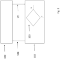
- the vehicle If the vehicle receives a request to release the parking brake, for example by means of an operator, the vehicle switches to state 102 (as shown by arrow 101). In state 102, the hydraulic transmission is checked and controlled and the parking brake is released only if the check in 103 (which will be described in detail in the following paragraph) has given a positive result. However, there are conditions, which will be described later, in which the check on this variable does not have to be performed as it is unnecessary and it is possible to proceed by directly releasing the parking brake.
- the detection of whether the said vehicle is facing upwards or downwards is performed by reading whether the pressure difference up and downstream of the said second hydraulic machine 14 is positive or negative. Alternatively, this may be established using means configured to measure the gradient of the ground along which the said vehicle is parked.
- the check on this variable must be carried out, the current absolute value of the variable described above is measured (or calculated in the case of the torque) and compared with the absolute value of the same variable in state 100. If the value is greater, then the parking brake can be released. If this state has not yet occurred, the check on the variable is repeated until this state occurs and it is therefore possible to release the parking brake and return from state 104 to state 100 until a new command to engage the parking brake is received.
- the first two situations arise in the event that the vehicle is stopped while being driven upwards and the driving brake is engaged.
- the check described above takes place.
- the current value of one of the pressure-dependent quantities is compared with the absolute value of the same variable before the vehicle was stopped. If the current value is greater than or equal to the value from before the vehicle was stopped, then the parking brake can be released. If, on the other hand, the current value is lower, the check will be repeated until this condition is met and the parking brake can be released.
- the check described above takes place.
- the current value of one of the pressure-dependent quantities is compared with the absolute value of the same variable before the vehicle was stopped. If the current value is greater than or equal to the value from before the vehicle was stopped, then the parking brake can be released. If, on the other hand, the current value is lower, the check will be repeated until this condition is met and the parking brake can be released.
Landscapes
- Engineering & Computer Science (AREA)
- Mechanical Engineering (AREA)
- Transportation (AREA)
- General Engineering & Computer Science (AREA)
- Regulating Braking Force (AREA)
- Braking Arrangements (AREA)
Claims (11)
- Verfahren zum Steuern einer Feststellbremse eines Fahrzeugs, wobei das Fahrzeug eine Antriebsmaschine (2), eine erste hydraulische Maschine (8) und eine zweite hydraulische Maschine (14) umfasst, wobei die Antriebsmaschine (2) konfiguriert ist, um die erste hydraulische Maschine (8) anzutreiben, wobei die erste hydraulische Maschine (8) ein erstes Fördervolumen aufweist und die zweite hydraulische Maschine (14) ein zweites Fördervolumen aufweist, in hydraulischer Verbindung mit der ersten hydraulischen Maschine (8) angeordnet und so konfiguriert ist, dass sie an Antriebseinrichtungen des Fahrzeugs gekoppelt ist, die konfiguriert sind, um eine Bewegung des Fahrzeugs bereitzustellen, wobei das Verfahren dadurch gekennzeichnet ist, dass
vor einem Lösen der Feststellbremse eine von einer Differenz zwischen dem Druck vor und hinter der zweiten hydraulischen Maschine (14) abhängige Variable mit derselben Variable, die vor einer Feststellung der Feststellbremse gemessen wird, verglichen wird, wobei die Feststellbremse gelöst wird, wenn der Absolutwert der Variable, die vor dem Lösen der Feststellbremse gemessen wird, größer ist als der Absolutwert derselben Variable, die vor der Feststellung der Feststellbremse gemessen wird. - Verfahren nach Anspruch 1, wobei die Variable der Absolutwert des durch die erste hydraulische Maschine (8) realisierten Drucks ist.
- Verfahren nach Anspruch 1, wobei die Variable mit dem Drehmoment der zweiten hydraulischen Maschine (14) korrespondiert, wobei das Drehmoment nach dem Messen der Differenz zwischen dem Druck vor und hinter der zweiten hydraulischen Maschine (14) und vorzugsweise des Fördervolumens der zweiten hydraulischen Maschine (8) berechnet wird.
- Verfahren nach Anspruch 1, wobei die Variable mit dem Drehmoment der zweiten hydraulischen Maschine (14) korrespondiert, wobei das Drehmoment nach dem Messen der Differenz zwischen dem Druck vor und hinter der zweiten hydraulischen Maschine (14) und vorzugsweise des Fördervolumens der zweiten hydraulischen Maschine (8) berechnet wird, von dem das durch die Beschleunigung des Fahrzeugs verursachte Drehmoment subtrahiert wird, um ein nur durch die Last des Fahrzeugs verursachtes Drehmoment zu erhalten.
- Verfahren nach einem der Ansprüche 1 bis 4, wobei der Vergleich des Absolutwerts der Variable nur unter einer der folgenden Bedingungen ausgeführt wird:wenn sich das Fahrzeug auf einer Steigung befindet und wenn eine Notwendigkeit des Lösens der Feststellbremse zum Vorwärtsfahren auf der Steigung gegeben ist; undwenn sich das Fahrzeug auf einem Gefälle befindet und wenn eine Aufforderung zum Lösen der Feststellbremse zum Zurückfahren auf dem Gefälle vorliegt.
- Verfahren nach einem der Ansprüche 1 bis 5, wobei die Feststellbremse gelöst wird, ohne den Vergleich des Absolutwerts der Variable unter einer der folgenden Bedingungen durchzuführen:
wenn sich das Fahrzeug auf einer Steigung befindet und wenn eine Notwendigkeit des Lösens der Feststellbremse zum Zurückfahren auf der Steigung gegeben ist; und wenn sich das Fahrzeug auf einem Gefälle befindet und wenn eine Notwendigkeit des Lösens der Feststellbremse zum Vorwärtsfahren auf dem Gefälle gegeben ist. - Verfahren nach Anspruch 5 oder 6, wobei die Erkennung, ob sich das Fahrzeug auf einer Steigung oder auf einem Gefälle befindet, mittels des Zeichens der Differenz zwischen dem Druck vor und hinter der zweiten hydraulischen Maschine (14) bereitgestellt wird.
- Verfahren nach Anspruch 5 oder 6, wobei die Erkennung, ob sich das Fahrzeug auf einer Steigung oder auf einem Gefälle befindet, mittels Erkennungseinrichtungen, die konfiguriert sind, um die Steigung oder das Gefälle des Bodens, auf dem das Fahrzeug positioniert ist, zu erkennen, bereitgestellt wird.
- Verfahren nach einem der Ansprüche 1 bis 8, wobei das Verfahren die folgenden Schritte umfasst:a. Empfangen eines Befehls zum Feststellen der Feststellbremse in dem Fahrzeug;b. Messen einer Differenz zwischen dem Druck vor und hinter der zweiten hydraulischen Maschine (14) und vorzugsweise des Fördervolumens der zweiten hydraulischen Maschine (14);c. Feststellen der Feststellbremse;d. Empfangen eines Befehls zum Lösen der Feststellbremse;e. Lösen der Feststellbremse, wenn der Absolutwert der Variable, die vor dem Lösen der Feststellbremse gemessen wird, größer ist als der Absolutwert derselben Variable, die vor der Feststellung der Feststellbremse gemessen wird.
- Verfahren nach einem der Ansprüche 1 bis 9, wobei das Fahrzeug eine mobile Arbeitsmaschine ist.
- Verfahren nach einem der Ansprüche 1 bis 10, wobei das erste Fördervolumen der ersten hydraulischen Maschine (8) so konfiguriert ist, dass es angepasst werden kann, und wobei das zweite Fördervolumen der zweiten hydraulischen Maschine (14) vorzugsweise angepasst werden kann.
Applications Claiming Priority (1)
| Application Number | Priority Date | Filing Date | Title |
|---|---|---|---|
| IT102021000001601A IT202100001601A1 (it) | 2021-01-27 | 2021-01-27 | Metodo di controllo di un freno di stazionamento di un veicolo |
Publications (2)
| Publication Number | Publication Date |
|---|---|
| EP4035957A1 EP4035957A1 (de) | 2022-08-03 |
| EP4035957B1 true EP4035957B1 (de) | 2023-09-06 |
Family
ID=75439262
Family Applications (1)
| Application Number | Title | Priority Date | Filing Date |
|---|---|---|---|
| EP22152609.8A Active EP4035957B1 (de) | 2021-01-27 | 2022-01-21 | Verfahren zur steuerung einer feststellbremse eines fahrzeugs |
Country Status (2)
| Country | Link |
|---|---|
| EP (1) | EP4035957B1 (de) |
| IT (1) | IT202100001601A1 (de) |
Family Cites Families (2)
| Publication number | Priority date | Publication date | Assignee | Title |
|---|---|---|---|---|
| DE102011008707B4 (de) * | 2011-01-17 | 2024-11-21 | Linde Material Handling Gmbh | Mobile Arbeitsmaschine, insbesondere Flurförderzeug |
| EP2748491B1 (de) * | 2011-08-25 | 2018-02-07 | CNH Industrial Italia S.p.A. | Proportionale parkbremssteuerung in kooperation mit dem betrieb eines stufenlosen getriebes |
-
2021
- 2021-01-27 IT IT102021000001601A patent/IT202100001601A1/it unknown
-
2022
- 2022-01-21 EP EP22152609.8A patent/EP4035957B1/de active Active
Also Published As
| Publication number | Publication date |
|---|---|
| IT202100001601A1 (it) | 2022-07-27 |
| EP4035957A1 (de) | 2022-08-03 |
Similar Documents
| Publication | Publication Date | Title |
|---|---|---|
| US7926267B2 (en) | Hystat transmission having pressure override control | |
| EP2802529B1 (de) | Verfahren zum erhalten eines vollständigen bereichs von hubgeschwindigkeiten mittels eines einzigen eingangs | |
| US7856817B2 (en) | Hydraulic drive system | |
| EP2687704B1 (de) | Antriebssteuervorrichtung für ein nutzfahrzeug | |
| CA2605049C (en) | Anti-overspeed system for vehicle and associated method | |
| JP5092059B1 (ja) | 作業車両及び作業車両の制御方法 | |
| US20100024412A1 (en) | Control Apparatus for Working Vehicle | |
| US10071719B2 (en) | Hydrostatic traction drive in closed hydraulic circuit and method for controlling the hydrostatic traction drive | |
| EP2589836A1 (de) | Wegsteuerungsvorrichtung für arbeitsmaschinen | |
| AU2021311138B2 (en) | Hydraulic retarding control system | |
| EP0589870A1 (de) | Elektrohydraulisches steuergerät für einen antriebsstrang eines fahrzeugs. | |
| AU2009285867A1 (en) | Control system and method for braking a hydrostatic drive machine | |
| CN103790876B (zh) | 一种闭式液压传动系统 | |
| EP1979220B1 (de) | Steuersystem für die rahmenlenkung eines fahrzeugs und verfahren zur steuerung von zwei lenkzylindern in einem rahmengelenkten fahrzeug | |
| US8918258B2 (en) | System and method for avoiding engine underspeed and stall | |
| KR20050098301A (ko) | 이동 차량용 동력 전달 계통 | |
| EP4035957B1 (de) | Verfahren zur steuerung einer feststellbremse eines fahrzeugs | |
| GB2275761A (en) | Improvements in braking vehicles with hydrostatic drive | |
| EP3868620B1 (de) | Mit einer hydrostatischen antriebseinheit angetriebenes fahrzeug und bremsverfahren | |
| CN101500836A (zh) | 具有液压动力辅助的车辆传动系统 | |
| JP2835996B2 (ja) | 産業車両の荷役及び走行制御装置 | |
| JP2006521512A (ja) | 動力伝達系を作動させる方法 | |
| CN203717499U (zh) | 一种闭式液压传动系统 | |
| CN219115419U (zh) | 用于工程机械的液压辅助制动系统和工程机械 | |
| EP4299953B1 (de) | Verfahren und steuersystem eines hydraulischen getriebes eines arbeits- oder landwirtschaftlichen fahrzeugs |
Legal Events
| Date | Code | Title | Description |
|---|---|---|---|
| PUAI | Public reference made under article 153(3) epc to a published international application that has entered the european phase |
Free format text: ORIGINAL CODE: 0009012 |
|
| STAA | Information on the status of an ep patent application or granted ep patent |
Free format text: STATUS: THE APPLICATION HAS BEEN PUBLISHED |
|
| AK | Designated contracting states |
Kind code of ref document: A1 Designated state(s): AL AT BE BG CH CY CZ DE DK EE ES FI FR GB GR HR HU IE IS IT LI LT LU LV MC MK MT NL NO PL PT RO RS SE SI SK SM TR |
|
| STAA | Information on the status of an ep patent application or granted ep patent |
Free format text: STATUS: REQUEST FOR EXAMINATION WAS MADE |
|
| 17P | Request for examination filed |
Effective date: 20230203 |
|
| RBV | Designated contracting states (corrected) |
Designated state(s): AL AT BE BG CH CY CZ DE DK EE ES FI FR GB GR HR HU IE IS IT LI LT LU LV MC MK MT NL NO PL PT RO RS SE SI SK SM TR |
|
| GRAP | Despatch of communication of intention to grant a patent |
Free format text: ORIGINAL CODE: EPIDOSNIGR1 |
|
| STAA | Information on the status of an ep patent application or granted ep patent |
Free format text: STATUS: GRANT OF PATENT IS INTENDED |
|
| INTG | Intention to grant announced |
Effective date: 20230602 |
|
| GRAS | Grant fee paid |
Free format text: ORIGINAL CODE: EPIDOSNIGR3 |
|
| GRAA | (expected) grant |
Free format text: ORIGINAL CODE: 0009210 |
|
| STAA | Information on the status of an ep patent application or granted ep patent |
Free format text: STATUS: THE PATENT HAS BEEN GRANTED |
|
| AK | Designated contracting states |
Kind code of ref document: B1 Designated state(s): AL AT BE BG CH CY CZ DE DK EE ES FI FR GB GR HR HU IE IS IT LI LT LU LV MC MK MT NL NO PL PT RO RS SE SI SK SM TR |
|
| REG | Reference to a national code |
Ref country code: GB Ref legal event code: FG4D |
|
| REG | Reference to a national code |
Ref country code: CH Ref legal event code: EP |
|
| REG | Reference to a national code |
Ref country code: DE Ref legal event code: R096 Ref document number: 602022000424 Country of ref document: DE |
|
| REG | Reference to a national code |
Ref country code: IE Ref legal event code: FG4D |
|
| REG | Reference to a national code |
Ref country code: LT Ref legal event code: MG9D |
|
| REG | Reference to a national code |
Ref country code: NL Ref legal event code: MP Effective date: 20230906 |
|
| PG25 | Lapsed in a contracting state [announced via postgrant information from national office to epo] |
Ref country code: GR Free format text: LAPSE BECAUSE OF FAILURE TO SUBMIT A TRANSLATION OF THE DESCRIPTION OR TO PAY THE FEE WITHIN THE PRESCRIBED TIME-LIMIT Effective date: 20231207 |
|
| PG25 | Lapsed in a contracting state [announced via postgrant information from national office to epo] |
Ref country code: SE Free format text: LAPSE BECAUSE OF FAILURE TO SUBMIT A TRANSLATION OF THE DESCRIPTION OR TO PAY THE FEE WITHIN THE PRESCRIBED TIME-LIMIT Effective date: 20230906 Ref country code: RS Free format text: LAPSE BECAUSE OF FAILURE TO SUBMIT A TRANSLATION OF THE DESCRIPTION OR TO PAY THE FEE WITHIN THE PRESCRIBED TIME-LIMIT Effective date: 20230906 Ref country code: NO Free format text: LAPSE BECAUSE OF FAILURE TO SUBMIT A TRANSLATION OF THE DESCRIPTION OR TO PAY THE FEE WITHIN THE PRESCRIBED TIME-LIMIT Effective date: 20231206 Ref country code: LV Free format text: LAPSE BECAUSE OF FAILURE TO SUBMIT A TRANSLATION OF THE DESCRIPTION OR TO PAY THE FEE WITHIN THE PRESCRIBED TIME-LIMIT Effective date: 20230906 Ref country code: LT Free format text: LAPSE BECAUSE OF FAILURE TO SUBMIT A TRANSLATION OF THE DESCRIPTION OR TO PAY THE FEE WITHIN THE PRESCRIBED TIME-LIMIT Effective date: 20230906 Ref country code: HR Free format text: LAPSE BECAUSE OF FAILURE TO SUBMIT A TRANSLATION OF THE DESCRIPTION OR TO PAY THE FEE WITHIN THE PRESCRIBED TIME-LIMIT Effective date: 20230906 Ref country code: GR Free format text: LAPSE BECAUSE OF FAILURE TO SUBMIT A TRANSLATION OF THE DESCRIPTION OR TO PAY THE FEE WITHIN THE PRESCRIBED TIME-LIMIT Effective date: 20231207 Ref country code: FI Free format text: LAPSE BECAUSE OF FAILURE TO SUBMIT A TRANSLATION OF THE DESCRIPTION OR TO PAY THE FEE WITHIN THE PRESCRIBED TIME-LIMIT Effective date: 20230906 |
|
| REG | Reference to a national code |
Ref country code: AT Ref legal event code: MK05 Ref document number: 1608159 Country of ref document: AT Kind code of ref document: T Effective date: 20230906 |
|
| PG25 | Lapsed in a contracting state [announced via postgrant information from national office to epo] |
Ref country code: NL Free format text: LAPSE BECAUSE OF FAILURE TO SUBMIT A TRANSLATION OF THE DESCRIPTION OR TO PAY THE FEE WITHIN THE PRESCRIBED TIME-LIMIT Effective date: 20230906 |
|
| PG25 | Lapsed in a contracting state [announced via postgrant information from national office to epo] |
Ref country code: IS Free format text: LAPSE BECAUSE OF FAILURE TO SUBMIT A TRANSLATION OF THE DESCRIPTION OR TO PAY THE FEE WITHIN THE PRESCRIBED TIME-LIMIT Effective date: 20240106 |
|
| PG25 | Lapsed in a contracting state [announced via postgrant information from national office to epo] |
Ref country code: AT Free format text: LAPSE BECAUSE OF FAILURE TO SUBMIT A TRANSLATION OF THE DESCRIPTION OR TO PAY THE FEE WITHIN THE PRESCRIBED TIME-LIMIT Effective date: 20230906 |
|
| PG25 | Lapsed in a contracting state [announced via postgrant information from national office to epo] |
Ref country code: ES Free format text: LAPSE BECAUSE OF FAILURE TO SUBMIT A TRANSLATION OF THE DESCRIPTION OR TO PAY THE FEE WITHIN THE PRESCRIBED TIME-LIMIT Effective date: 20230906 |
|
| PG25 | Lapsed in a contracting state [announced via postgrant information from national office to epo] |
Ref country code: SM Free format text: LAPSE BECAUSE OF FAILURE TO SUBMIT A TRANSLATION OF THE DESCRIPTION OR TO PAY THE FEE WITHIN THE PRESCRIBED TIME-LIMIT Effective date: 20230906 Ref country code: RO Free format text: LAPSE BECAUSE OF FAILURE TO SUBMIT A TRANSLATION OF THE DESCRIPTION OR TO PAY THE FEE WITHIN THE PRESCRIBED TIME-LIMIT Effective date: 20230906 Ref country code: IS Free format text: LAPSE BECAUSE OF FAILURE TO SUBMIT A TRANSLATION OF THE DESCRIPTION OR TO PAY THE FEE WITHIN THE PRESCRIBED TIME-LIMIT Effective date: 20240106 Ref country code: ES Free format text: LAPSE BECAUSE OF FAILURE TO SUBMIT A TRANSLATION OF THE DESCRIPTION OR TO PAY THE FEE WITHIN THE PRESCRIBED TIME-LIMIT Effective date: 20230906 Ref country code: EE Free format text: LAPSE BECAUSE OF FAILURE TO SUBMIT A TRANSLATION OF THE DESCRIPTION OR TO PAY THE FEE WITHIN THE PRESCRIBED TIME-LIMIT Effective date: 20230906 Ref country code: CZ Free format text: LAPSE BECAUSE OF FAILURE TO SUBMIT A TRANSLATION OF THE DESCRIPTION OR TO PAY THE FEE WITHIN THE PRESCRIBED TIME-LIMIT Effective date: 20230906 Ref country code: AT Free format text: LAPSE BECAUSE OF FAILURE TO SUBMIT A TRANSLATION OF THE DESCRIPTION OR TO PAY THE FEE WITHIN THE PRESCRIBED TIME-LIMIT Effective date: 20230906 Ref country code: PT Free format text: LAPSE BECAUSE OF FAILURE TO SUBMIT A TRANSLATION OF THE DESCRIPTION OR TO PAY THE FEE WITHIN THE PRESCRIBED TIME-LIMIT Effective date: 20240108 Ref country code: SK Free format text: LAPSE BECAUSE OF FAILURE TO SUBMIT A TRANSLATION OF THE DESCRIPTION OR TO PAY THE FEE WITHIN THE PRESCRIBED TIME-LIMIT Effective date: 20230906 |
|
| PG25 | Lapsed in a contracting state [announced via postgrant information from national office to epo] |
Ref country code: PL Free format text: LAPSE BECAUSE OF FAILURE TO SUBMIT A TRANSLATION OF THE DESCRIPTION OR TO PAY THE FEE WITHIN THE PRESCRIBED TIME-LIMIT Effective date: 20230906 |
|
| REG | Reference to a national code |
Ref country code: DE Ref legal event code: R097 Ref document number: 602022000424 Country of ref document: DE |
|
| PG25 | Lapsed in a contracting state [announced via postgrant information from national office to epo] |
Ref country code: DK Free format text: LAPSE BECAUSE OF FAILURE TO SUBMIT A TRANSLATION OF THE DESCRIPTION OR TO PAY THE FEE WITHIN THE PRESCRIBED TIME-LIMIT Effective date: 20230906 |
|
| PLBE | No opposition filed within time limit |
Free format text: ORIGINAL CODE: 0009261 |
|
| STAA | Information on the status of an ep patent application or granted ep patent |
Free format text: STATUS: NO OPPOSITION FILED WITHIN TIME LIMIT |
|
| PG25 | Lapsed in a contracting state [announced via postgrant information from national office to epo] |
Ref country code: DK Free format text: LAPSE BECAUSE OF FAILURE TO SUBMIT A TRANSLATION OF THE DESCRIPTION OR TO PAY THE FEE WITHIN THE PRESCRIBED TIME-LIMIT Effective date: 20230906 Ref country code: SI Free format text: LAPSE BECAUSE OF FAILURE TO SUBMIT A TRANSLATION OF THE DESCRIPTION OR TO PAY THE FEE WITHIN THE PRESCRIBED TIME-LIMIT Effective date: 20230906 |
|
| 26N | No opposition filed |
Effective date: 20240607 |
|
| PG25 | Lapsed in a contracting state [announced via postgrant information from national office to epo] |
Ref country code: MC Free format text: LAPSE BECAUSE OF FAILURE TO SUBMIT A TRANSLATION OF THE DESCRIPTION OR TO PAY THE FEE WITHIN THE PRESCRIBED TIME-LIMIT Effective date: 20230906 |
|
| PG25 | Lapsed in a contracting state [announced via postgrant information from national office to epo] |
Ref country code: MC Free format text: LAPSE BECAUSE OF FAILURE TO SUBMIT A TRANSLATION OF THE DESCRIPTION OR TO PAY THE FEE WITHIN THE PRESCRIBED TIME-LIMIT Effective date: 20230906 |
|
| PG25 | Lapsed in a contracting state [announced via postgrant information from national office to epo] |
Ref country code: LU Free format text: LAPSE BECAUSE OF NON-PAYMENT OF DUE FEES Effective date: 20240121 |
|
| PG25 | Lapsed in a contracting state [announced via postgrant information from national office to epo] |
Ref country code: LU Free format text: LAPSE BECAUSE OF NON-PAYMENT OF DUE FEES Effective date: 20240121 |
|
| PG25 | Lapsed in a contracting state [announced via postgrant information from national office to epo] |
Ref country code: BE Free format text: LAPSE BECAUSE OF NON-PAYMENT OF DUE FEES Effective date: 20240131 |
|
| PG25 | Lapsed in a contracting state [announced via postgrant information from national office to epo] |
Ref country code: FR Free format text: LAPSE BECAUSE OF NON-PAYMENT OF DUE FEES Effective date: 20240131 |
|
| PG25 | Lapsed in a contracting state [announced via postgrant information from national office to epo] |
Ref country code: FR Free format text: LAPSE BECAUSE OF NON-PAYMENT OF DUE FEES Effective date: 20240131 Ref country code: BE Free format text: LAPSE BECAUSE OF NON-PAYMENT OF DUE FEES Effective date: 20240131 |
|
| REG | Reference to a national code |
Ref country code: BE Ref legal event code: MM Effective date: 20240131 |
|
| PG25 | Lapsed in a contracting state [announced via postgrant information from national office to epo] |
Ref country code: BG Free format text: LAPSE BECAUSE OF FAILURE TO SUBMIT A TRANSLATION OF THE DESCRIPTION OR TO PAY THE FEE WITHIN THE PRESCRIBED TIME-LIMIT Effective date: 20230906 |
|
| PG25 | Lapsed in a contracting state [announced via postgrant information from national office to epo] |
Ref country code: BG Free format text: LAPSE BECAUSE OF FAILURE TO SUBMIT A TRANSLATION OF THE DESCRIPTION OR TO PAY THE FEE WITHIN THE PRESCRIBED TIME-LIMIT Effective date: 20230906 |
|
| PG25 | Lapsed in a contracting state [announced via postgrant information from national office to epo] |
Ref country code: IE Free format text: LAPSE BECAUSE OF NON-PAYMENT OF DUE FEES Effective date: 20240121 |
|
| PG25 | Lapsed in a contracting state [announced via postgrant information from national office to epo] |
Ref country code: IE Free format text: LAPSE BECAUSE OF NON-PAYMENT OF DUE FEES Effective date: 20240121 |
|
| PG25 | Lapsed in a contracting state [announced via postgrant information from national office to epo] |
Ref country code: CY Free format text: LAPSE BECAUSE OF FAILURE TO SUBMIT A TRANSLATION OF THE DESCRIPTION OR TO PAY THE FEE WITHIN THE PRESCRIBED TIME-LIMIT; INVALID AB INITIO Effective date: 20220121 |
|
| REG | Reference to a national code |
Ref country code: CH Ref legal event code: PL |
|
| PG25 | Lapsed in a contracting state [announced via postgrant information from national office to epo] |
Ref country code: CH Free format text: LAPSE BECAUSE OF NON-PAYMENT OF DUE FEES Effective date: 20250131 |
|
| PG25 | Lapsed in a contracting state [announced via postgrant information from national office to epo] |
Ref country code: TR Free format text: LAPSE BECAUSE OF FAILURE TO SUBMIT A TRANSLATION OF THE DESCRIPTION OR TO PAY THE FEE WITHIN THE PRESCRIBED TIME-LIMIT Effective date: 20230906 |
|
| PGFP | Annual fee paid to national office [announced via postgrant information from national office to epo] |
Ref country code: DE Payment date: 20260319 Year of fee payment: 5 |
|
| PGFP | Annual fee paid to national office [announced via postgrant information from national office to epo] |
Ref country code: IT Payment date: 20260130 Year of fee payment: 5 |