EP4035941A1 - Automotive lighting and/or signalling device - Google Patents
Automotive lighting and/or signalling device Download PDFInfo
- Publication number
- EP4035941A1 EP4035941A1 EP22152968.8A EP22152968A EP4035941A1 EP 4035941 A1 EP4035941 A1 EP 4035941A1 EP 22152968 A EP22152968 A EP 22152968A EP 4035941 A1 EP4035941 A1 EP 4035941A1
- Authority
- EP
- European Patent Office
- Prior art keywords
- lighting
- signalling device
- light beam
- light
- light source
- Prior art date
- Legal status (The legal status is an assumption and is not a legal conclusion. Google has not performed a legal analysis and makes no representation as to the accuracy of the status listed.)
- Pending
Links
- 230000011664 signaling Effects 0.000 title claims abstract description 50
- 238000011144 upstream manufacturing Methods 0.000 claims description 4
- 239000000463 material Substances 0.000 description 3
- XECAHXYUAAWDEL-UHFFFAOYSA-N acrylonitrile butadiene styrene Chemical compound C=CC=C.C=CC#N.C=CC1=CC=CC=C1 XECAHXYUAAWDEL-UHFFFAOYSA-N 0.000 description 2
- 239000004676 acrylonitrile butadiene styrene Substances 0.000 description 2
- 229920000122 acrylonitrile butadiene styrene Polymers 0.000 description 2
- 238000004519 manufacturing process Methods 0.000 description 2
- 229920003229 poly(methyl methacrylate) Polymers 0.000 description 2
- 239000004417 polycarbonate Substances 0.000 description 2
- 239000004926 polymethyl methacrylate Substances 0.000 description 2
- 230000000712 assembly Effects 0.000 description 1
- 238000000429 assembly Methods 0.000 description 1
- 230000001419 dependent effect Effects 0.000 description 1
- 239000012994 photoredox catalyst Substances 0.000 description 1
- 229920000515 polycarbonate Polymers 0.000 description 1
- 239000011347 resin Substances 0.000 description 1
- 229920005989 resin Polymers 0.000 description 1
Images

Classifications
-
- B—PERFORMING OPERATIONS; TRANSPORTING
- B60—VEHICLES IN GENERAL
- B60Q—ARRANGEMENT OF SIGNALLING OR LIGHTING DEVICES, THE MOUNTING OR SUPPORTING THEREOF OR CIRCUITS THEREFOR, FOR VEHICLES IN GENERAL
- B60Q1/00—Arrangement of optical signalling or lighting devices, the mounting or supporting thereof or circuits therefor
- B60Q1/0029—Spatial arrangement
- B60Q1/0041—Spatial arrangement of several lamps in relation to each other
- B60Q1/0058—Stacked, i.e. one lamp located behind the other in the optical axis direction
-
- B—PERFORMING OPERATIONS; TRANSPORTING
- B60—VEHICLES IN GENERAL
- B60Q—ARRANGEMENT OF SIGNALLING OR LIGHTING DEVICES, THE MOUNTING OR SUPPORTING THEREOF OR CIRCUITS THEREFOR, FOR VEHICLES IN GENERAL
- B60Q1/00—Arrangement of optical signalling or lighting devices, the mounting or supporting thereof or circuits therefor
- B60Q1/26—Arrangement of optical signalling or lighting devices, the mounting or supporting thereof or circuits therefor the devices being primarily intended to indicate the vehicle, or parts thereof, or to give signals, to other traffic
- B60Q1/2607—Arrangement of optical signalling or lighting devices, the mounting or supporting thereof or circuits therefor the devices being primarily intended to indicate the vehicle, or parts thereof, or to give signals, to other traffic comprising at least two indicating lamps
-
- B—PERFORMING OPERATIONS; TRANSPORTING
- B60—VEHICLES IN GENERAL
- B60Q—ARRANGEMENT OF SIGNALLING OR LIGHTING DEVICES, THE MOUNTING OR SUPPORTING THEREOF OR CIRCUITS THEREFOR, FOR VEHICLES IN GENERAL
- B60Q1/00—Arrangement of optical signalling or lighting devices, the mounting or supporting thereof or circuits therefor
- B60Q1/26—Arrangement of optical signalling or lighting devices, the mounting or supporting thereof or circuits therefor the devices being primarily intended to indicate the vehicle, or parts thereof, or to give signals, to other traffic
- B60Q1/50—Arrangement of optical signalling or lighting devices, the mounting or supporting thereof or circuits therefor the devices being primarily intended to indicate the vehicle, or parts thereof, or to give signals, to other traffic for indicating other intentions or conditions, e.g. request for waiting or overtaking
- B60Q1/503—Arrangement of optical signalling or lighting devices, the mounting or supporting thereof or circuits therefor the devices being primarily intended to indicate the vehicle, or parts thereof, or to give signals, to other traffic for indicating other intentions or conditions, e.g. request for waiting or overtaking using luminous text or symbol displays in or on the vehicle, e.g. static text
- B60Q1/5035—Arrangement of optical signalling or lighting devices, the mounting or supporting thereof or circuits therefor the devices being primarily intended to indicate the vehicle, or parts thereof, or to give signals, to other traffic for indicating other intentions or conditions, e.g. request for waiting or overtaking using luminous text or symbol displays in or on the vehicle, e.g. static text electronic displays
-
- F—MECHANICAL ENGINEERING; LIGHTING; HEATING; WEAPONS; BLASTING
- F21—LIGHTING
- F21S—NON-PORTABLE LIGHTING DEVICES; SYSTEMS THEREOF; VEHICLE LIGHTING DEVICES SPECIALLY ADAPTED FOR VEHICLE EXTERIORS
- F21S43/00—Signalling devices specially adapted for vehicle exteriors, e.g. brake lamps, direction indicator lights or reversing lights
- F21S43/10—Signalling devices specially adapted for vehicle exteriors, e.g. brake lamps, direction indicator lights or reversing lights characterised by the light source
- F21S43/13—Signalling devices specially adapted for vehicle exteriors, e.g. brake lamps, direction indicator lights or reversing lights characterised by the light source characterised by the type of light source
- F21S43/14—Light emitting diodes [LED]
-
- F—MECHANICAL ENGINEERING; LIGHTING; HEATING; WEAPONS; BLASTING
- F21—LIGHTING
- F21S—NON-PORTABLE LIGHTING DEVICES; SYSTEMS THEREOF; VEHICLE LIGHTING DEVICES SPECIALLY ADAPTED FOR VEHICLE EXTERIORS
- F21S43/00—Signalling devices specially adapted for vehicle exteriors, e.g. brake lamps, direction indicator lights or reversing lights
- F21S43/10—Signalling devices specially adapted for vehicle exteriors, e.g. brake lamps, direction indicator lights or reversing lights characterised by the light source
- F21S43/13—Signalling devices specially adapted for vehicle exteriors, e.g. brake lamps, direction indicator lights or reversing lights characterised by the light source characterised by the type of light source
- F21S43/15—Strips of light sources
-
- F—MECHANICAL ENGINEERING; LIGHTING; HEATING; WEAPONS; BLASTING
- F21—LIGHTING
- F21S—NON-PORTABLE LIGHTING DEVICES; SYSTEMS THEREOF; VEHICLE LIGHTING DEVICES SPECIALLY ADAPTED FOR VEHICLE EXTERIORS
- F21S43/00—Signalling devices specially adapted for vehicle exteriors, e.g. brake lamps, direction indicator lights or reversing lights
- F21S43/30—Signalling devices specially adapted for vehicle exteriors, e.g. brake lamps, direction indicator lights or reversing lights characterised by reflectors
- F21S43/31—Optical layout thereof
-
- F—MECHANICAL ENGINEERING; LIGHTING; HEATING; WEAPONS; BLASTING
- F21—LIGHTING
- F21S—NON-PORTABLE LIGHTING DEVICES; SYSTEMS THEREOF; VEHICLE LIGHTING DEVICES SPECIALLY ADAPTED FOR VEHICLE EXTERIORS
- F21S43/00—Signalling devices specially adapted for vehicle exteriors, e.g. brake lamps, direction indicator lights or reversing lights
- F21S43/40—Signalling devices specially adapted for vehicle exteriors, e.g. brake lamps, direction indicator lights or reversing lights characterised by the combination of reflectors and refractors
-
- B—PERFORMING OPERATIONS; TRANSPORTING
- B60—VEHICLES IN GENERAL
- B60Q—ARRANGEMENT OF SIGNALLING OR LIGHTING DEVICES, THE MOUNTING OR SUPPORTING THEREOF OR CIRCUITS THEREFOR, FOR VEHICLES IN GENERAL
- B60Q1/00—Arrangement of optical signalling or lighting devices, the mounting or supporting thereof or circuits therefor
- B60Q1/26—Arrangement of optical signalling or lighting devices, the mounting or supporting thereof or circuits therefor the devices being primarily intended to indicate the vehicle, or parts thereof, or to give signals, to other traffic
- B60Q1/50—Arrangement of optical signalling or lighting devices, the mounting or supporting thereof or circuits therefor the devices being primarily intended to indicate the vehicle, or parts thereof, or to give signals, to other traffic for indicating other intentions or conditions, e.g. request for waiting or overtaking
- B60Q1/545—Arrangement of optical signalling or lighting devices, the mounting or supporting thereof or circuits therefor the devices being primarily intended to indicate the vehicle, or parts thereof, or to give signals, to other traffic for indicating other intentions or conditions, e.g. request for waiting or overtaking for indicating other traffic conditions, e.g. fog, heavy traffic
-
- F—MECHANICAL ENGINEERING; LIGHTING; HEATING; WEAPONS; BLASTING
- F21—LIGHTING
- F21W—INDEXING SCHEME ASSOCIATED WITH SUBCLASSES F21K, F21L, F21S and F21V, RELATING TO USES OR APPLICATIONS OF LIGHTING DEVICES OR SYSTEMS
- F21W2103/00—Exterior vehicle lighting devices for signalling purposes
-
- F—MECHANICAL ENGINEERING; LIGHTING; HEATING; WEAPONS; BLASTING
- F21—LIGHTING
- F21W—INDEXING SCHEME ASSOCIATED WITH SUBCLASSES F21K, F21L, F21S and F21V, RELATING TO USES OR APPLICATIONS OF LIGHTING DEVICES OR SYSTEMS
- F21W2104/00—Exterior vehicle lighting devices for decorative purposes
Definitions
- the present invention relates to an automotive lighting and/or signalling device.
- automotive lighting and/or signalling device here is used with a very broad meaning in order to comprise an automotive light, whether a rear or front automotive light, the latter also called headlight or headlamp.
- an automotive light is a device intended to provide at least one lighting and/or signalling function of the vehicle, such as a position light, a turn signal, a brake light, a rear fog lamp, a reversing light, a dipped beam headlamp, a main beam headlamp, and the like.
- the term is also understood to comprise a map light, a light for a dashboard or part thereof; thus, the automotive lighting and/or signalling device may be placed either inside or outside the vehicle.
- said automotive lighting and/or signalling devices substantially comprise a hollow container body, which internally accommodates at least one light source and which is closed by an external lenticular body.
- the lighting and/or signalling devices on the market today are provided with lighting assemblies in which the light source, in particular of the LED type, is coupled, for example to at least one light guide which receives the light beam produced by the light source and transmits it towards the lenticular body.
- said lighting and/or signalling devices have to perform not only photometric functions, such as, for example the function of position lights, turn signals, brake lights, reversing lights, rear fog lamps, and the like, but they have also to perform merely aesthetical and/or information communicating functions.
- lighting and/or signalling devices have now become an integral and characterizing part of the design of a vehicle and are used to perform several functions with respect to the specific ones associated with automotive lighting.
- lights having an aesthetical and or messaging nature are associated with the classical lighting and/or signalling lights of a lighting and/or signalling device.
- making such additional lights often is hindered by the curved geometry of the lighting and/or signalling device.
- RGB light sources intended to create a pattern/message/figure to be displayed sometimes do not have an adequate place within the lighting and/or signalling device in order to create the desired image.
- a lighting and/or signalling device such as an automotive light, to which the following disclosure refers without however losing in generality, is indicated as a whole by numeral 4.
- the term lighting and/or signalling device may indifferently mean a rear automotive light or a front automotive light, the latter also called a headlight or headlamp, comprising an external vehicle light having a lighting and/or signalling function, such as for example a position light, which may be a front, rear, side position light, a turn signal light, a brake light, a rear fog lamp, a main beam headlamp, a dipped beam headlamp, and the like.
- a position light which may be a front, rear, side position light, a turn signal light, a brake light, a rear fog lamp, a main beam headlamp, a dipped beam headlamp, and the like.
- the term lighting and/or signalling device also means an indoor map light, a light for a dashboard or part thereof, a display, etc.
- the device in its signalling function may comprise the possibility of sending light signals, logos, but also words and lit messages of any kind.
- the lighting and/or signalling device 4 comprises a container body or housing 8, usually made of polymeric material, such as, for example acrylonitrile butadiene styrene or ABS, which conventionally allows the fixing of the lighting and/or signalling device 4 to the related vehicle or to any type of support.
- polymeric material such as, for example acrylonitrile butadiene styrene or ABS, which conventionally allows the fixing of the lighting and/or signalling device 4 to the related vehicle or to any type of support.
- the container body or housing 8 may have any shape and size, and also positioning: for example, the container body 8 may also not be directly connected to the bodywork or other external fixings of the associable vehicle.
- the container body 8 may also be fixed inside the vehicle, for example on the instrument panel, on the dashboard, on the parcel shelf, and so on.
- the container body 8 delimits a containment seat 12 which accommodates a plurality of components of said lighting and/or signalling device.
- the containment seat 12 in particular accommodates a plurality of light sources adapted to emit a light beam, arranged and supported in said containment seat 12, as better described below.
- a lenticular body 20 may be placed at least partially closing the container body 8, so as to close said containment seat 12 which accommodates the at least one light source 16.
- the lenticular body 20 may be external to the lighting and/or signalling device 4, so as to define at least one external wall of the lighting and/or signalling device directly subjected to the atmosphere.
- the material of the lenticular body 20 is of polymeric type, i.e., a resin such as PMMA (poly methyl methacrylate, PC (polycarbonate) and the like. Said material of the lenticular body is therefore at least partially transparent or semitransparent or translucent, one or more opaque portions being able to be included.
- the lenticular body 20 is thus adapted to be at least partially crossed by the light beam produced by the light sources, which is transmitted outside the containment seat 12, as better described below.
- the lighting and/or signalling device 4 comprises an electronic board or printed circuit board 24 which supports a first light source 32 performing a first lighting function by emitting a first light beam and a second light source 28 performing a second lighting function by emitting a second light beam.
- the lighting and/or signalling device 4 further comprises a first reflector element 40 which comprises a front wall 44 which intercepts and reflects the first light beam emitted by the first light source 32 along said prevailing propagation direction X-X and a second reflector 36 which intercepts and reflects the second light beam emitted by the second light source 28 in a prevailing propagation direction X-X.
- a first reflector element 40 which comprises a front wall 44 which intercepts and reflects the first light beam emitted by the first light source 32 along said prevailing propagation direction X-X and a second reflector 36 which intercepts and reflects the second light beam emitted by the second light source 28 in a prevailing propagation direction X-X.
- the second reflector element 36 is located upstream of the first reflector element 40 along said prevailing propagation direction X-X so that the second light beam strikes a back wall 48 of the first reflector element 40 opposite to said front wall 44.
- the second light source 28 is located upstream of the first light source 32 with respect to said prevailing propagation direction X-X.
- said first reflector element 40 is a semitransparent element so as to reflect the first light beam striking its front wall 44 and to be simultaneously crossed by the second light beam emitted by the second light source 28 striking its rear wall 48.
- the second light source 28 preferably comprises an LED light source or a laser source.
- the first light source 32 comprises a plurality of mini-LEDs, micro-LEDs.
- said first and second light sources 32, 28 are adjacent and are reciprocally independently operable, each emitting its own light beam.
- the second light sources are to be reciprocally independently operable in order to display any type of image and/or animation.
- Said electronic board or printed circuit board 24 may be a planar support having a plate configuration; said first light sources 32 preferably are arranged on said plate at least partially along curvilinear trajectories S-S.
- the first light sources 32 comprise a plurality of mini-LEDs or micro-LEDs, preferably of RGB type, arranged along said plate, so as to create a pattern/message/figure reflected on the front wall 44 of the first reflector element 40.
- a pattern/message/figure may be created, which implies a well-defined arrangement of the RGB type light sources, also in the presence of curvilinear profiles of the lighting and/or signalling device 4, each RGB type mini-LED being freely placeable according to needs without position constraints.
- Said plate may also in turn be shaped so as to be a curvilinear element.
- the first and second light sources 32, 28 are connected or powered so as to be operable separately and/or together, so as to be able to emit their respective light beams separately or simultaneously.
- the respective light sources may be simultaneously or separately operated, and also a specific animation obtained by conveniently operating the plurality of first light sources 32 may also support a classical function of light signalling (such as, for example a stop signal).
- a classical function of light signalling such as, for example a stop signal
- the electronic board or printed circuit board 24 may be fixed to the container body 8 or to a support structure in turn fixed to the container body 8.
- the present invention allows the drawbacks introduced in the known art to be overcome.
- the automotive lighting and/or signalling device allows both the photometric functions and the aesthetical functions to be performed while keeping curbed the related production and assembly costs.
- said lighting and/or signalling device perform the classical photochromic functions (for example, position light, stop light, reverse light, turn signal light) conventionally by means of the first light sources, but it may also provide further signalling functions by means of animations, written words, various symbols, by virtue of a suitable switching ON of the second micro-LED or mini-LED light sources.
- classical photochromic functions for example, position light, stop light, reverse light, turn signal light
- a curved display is obtained which follows the curvature of the lenticular body and therefore, for example of the bodywork, so as to be perfectly integrated in the vehicle body on which the lighting and/or signalling device is applied.
- the automotive lighting and/or signalling device according to the present invention is reliable.
Landscapes
- Engineering & Computer Science (AREA)
- General Engineering & Computer Science (AREA)
- Mechanical Engineering (AREA)
- Physics & Mathematics (AREA)
- Microelectronics & Electronic Packaging (AREA)
- Optics & Photonics (AREA)
- Preparation Of Compounds By Using Micro-Organisms (AREA)
- Non-Portable Lighting Devices Or Systems Thereof (AREA)
Abstract
Description
- The present invention relates to an automotive lighting and/or signalling device.
- The term automotive lighting and/or signalling device here is used with a very broad meaning in order to comprise an automotive light, whether a rear or front automotive light, the latter also called headlight or headlamp.
- As known, an automotive light is a device intended to provide at least one lighting and/or signalling function of the vehicle, such as a position light, a turn signal, a brake light, a rear fog lamp, a reversing light, a dipped beam headlamp, a main beam headlamp, and the like.
- Furthermore, the term is also understood to comprise a map light, a light for a dashboard or part thereof; thus, the automotive lighting and/or signalling device may be placed either inside or outside the vehicle.
- As known, said automotive lighting and/or signalling devices substantially comprise a hollow container body, which internally accommodates at least one light source and which is closed by an external lenticular body.
- The lighting and/or signalling devices on the market today are provided with lighting assemblies in which the light source, in particular of the LED type, is coupled, for example to at least one light guide which receives the light beam produced by the light source and transmits it towards the lenticular body.
- Over the last few years, said lighting and/or signalling devices have to perform not only photometric functions, such as, for example the function of position lights, turn signals, brake lights, reversing lights, rear fog lamps, and the like, but they have also to perform merely aesthetical and/or information communicating functions.
- In other words, lighting and/or signalling devices have now become an integral and characterizing part of the design of a vehicle and are used to perform several functions with respect to the specific ones associated with automotive lighting. In greater detail, lights having an aesthetical and or messaging nature are associated with the classical lighting and/or signalling lights of a lighting and/or signalling device. However, making such additional lights often is hindered by the curved geometry of the lighting and/or signalling device. For example, RGB light sources intended to create a pattern/message/figure to be displayed sometimes do not have an adequate place within the lighting and/or signalling device in order to create the desired image.
- It is the object of the present invention to provide a lighting and/or signalling device which is able to perform both the photometric functions and additional aesthetical functions described above while ensuring reduced production costs and increased reliability.
- Such a need is met by an automotive lighting and/or signalling device according to claim 1.
- Other embodiments of the present invention are described in the dependent claims.
- Further features and advantages of the present invention will be more comprehensible from the following description of preferred and non-limiting embodiments thereof, in which:
-
Figure 1 shows a perspective view of a vehicle which incorporates, on the rear portion thereof, a lighting and/or signalling device according to an embodiment of the present invention, in different lighting configurations; -
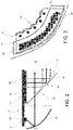
Figures 2 to 3 show sectional views of the lighting and/or signalling device inFigure 1 . - The elements or parts of elements common to the embodiments described below will be indicated using the same numerals.
- With reference to the aforesaid drawings, a lighting and/or signalling device, such as an automotive light, to which the following disclosure refers without however losing in generality, is indicated as a whole by
numeral 4. - As mentioned above, the term lighting and/or signalling device may indifferently mean a rear automotive light or a front automotive light, the latter also called a headlight or headlamp, comprising an external vehicle light having a lighting and/or signalling function, such as for example a position light, which may be a front, rear, side position light, a turn signal light, a brake light, a rear fog lamp, a main beam headlamp, a dipped beam headlamp, and the like.
- Moreover, the term lighting and/or signalling device also means an indoor map light, a light for a dashboard or part thereof, a display, etc.
- Thus, as better described below, the device in its signalling function may comprise the possibility of sending light signals, logos, but also words and lit messages of any kind.
- The lighting and/or
signalling device 4 comprises a container body orhousing 8, usually made of polymeric material, such as, for example acrylonitrile butadiene styrene or ABS, which conventionally allows the fixing of the lighting and/orsignalling device 4 to the related vehicle or to any type of support. - For the purposes of the present invention, the container body or
housing 8 may have any shape and size, and also positioning: for example, thecontainer body 8 may also not be directly connected to the bodywork or other external fixings of the associable vehicle. - As shown, the
container body 8 may also be fixed inside the vehicle, for example on the instrument panel, on the dashboard, on the parcel shelf, and so on. - The
container body 8 delimits acontainment seat 12 which accommodates a plurality of components of said lighting and/or signalling device. - The
containment seat 12 in particular accommodates a plurality of light sources adapted to emit a light beam, arranged and supported in saidcontainment seat 12, as better described below. - For example, a
lenticular body 20 may be placed at least partially closing thecontainer body 8, so as to close saidcontainment seat 12 which accommodates the at least one light source 16. - For the purposes of the present invention, the
lenticular body 20 may be external to the lighting and/orsignalling device 4, so as to define at least one external wall of the lighting and/or signalling device directly subjected to the atmosphere. - According to possible embodiments, the material of the
lenticular body 20 is of polymeric type, i.e., a resin such as PMMA (poly methyl methacrylate, PC (polycarbonate) and the like. Said material of the lenticular body is therefore at least partially transparent or semitransparent or translucent, one or more opaque portions being able to be included. - The
lenticular body 20 is thus adapted to be at least partially crossed by the light beam produced by the light sources, which is transmitted outside thecontainment seat 12, as better described below. - The lighting and/or
signalling device 4 comprises an electronic board or printedcircuit board 24 which supports afirst light source 32 performing a first lighting function by emitting a first light beam and asecond light source 28 performing a second lighting function by emitting a second light beam. - The lighting and/or
signalling device 4 further comprises afirst reflector element 40 which comprises afront wall 44 which intercepts and reflects the first light beam emitted by thefirst light source 32 along said prevailing propagation direction X-X and asecond reflector 36 which intercepts and reflects the second light beam emitted by thesecond light source 28 in a prevailing propagation direction X-X. - The
second reflector element 36 is located upstream of thefirst reflector element 40 along said prevailing propagation direction X-X so that the second light beam strikes aback wall 48 of thefirst reflector element 40 opposite to saidfront wall 44. - The
second light source 28 is located upstream of thefirst light source 32 with respect to said prevailing propagation direction X-X. - Advantageously, said
first reflector element 40 is a semitransparent element so as to reflect the first light beam striking itsfront wall 44 and to be simultaneously crossed by the second light beam emitted by thesecond light source 28 striking itsrear wall 48. - The
second light source 28 preferably comprises an LED light source or a laser source. - The
first light source 32 comprises a plurality of mini-LEDs, micro-LEDs. - Preferably, said first and
second light sources - Said electronic board or printed
circuit board 24 may be a planar support having a plate configuration; saidfirst light sources 32 preferably are arranged on said plate at least partially along curvilinear trajectories S-S. - Preferably, the
first light sources 32 comprise a plurality of mini-LEDs or micro-LEDs, preferably of RGB type, arranged along said plate, so as to create a pattern/message/figure reflected on thefront wall 44 of thefirst reflector element 40. In other words, a pattern/message/figure may be created, which implies a well-defined arrangement of the RGB type light sources, also in the presence of curvilinear profiles of the lighting and/orsignalling device 4, each RGB type mini-LED being freely placeable according to needs without position constraints. - Said plate may also in turn be shaped so as to be a curvilinear element.
- Preferably, the first and
second light sources - Thereby, the respective light sources may be simultaneously or separately operated, and also a specific animation obtained by conveniently operating the plurality of
first light sources 32 may also support a classical function of light signalling (such as, for example a stop signal). - The electronic board or printed
circuit board 24 may be fixed to thecontainer body 8 or to a support structure in turn fixed to thecontainer body 8. - As may be appreciated by what is described, the present invention allows the drawbacks introduced in the known art to be overcome.
- In particular, the automotive lighting and/or signalling device according to the present invention allows both the photometric functions and the aesthetical functions to be performed while keeping curbed the related production and assembly costs.
- Not only may said lighting and/or signalling device perform the classical photochromic functions (for example, position light, stop light, reverse light, turn signal light) conventionally by means of the first light sources, but it may also provide further signalling functions by means of animations, written words, various symbols, by virtue of a suitable switching ON of the second micro-LED or mini-LED light sources.
- In fact, a curved display is obtained which follows the curvature of the lenticular body and therefore, for example of the bodywork, so as to be perfectly integrated in the vehicle body on which the lighting and/or signalling device is applied.
- Moreover, the automotive lighting and/or signalling device according to the present invention is reliable.
- Those skilled in the art, with the object of meeting contingent and specific needs, can make several changes and variants to the lighting and/or signalling devices described above, moreover all contained within the scope of the invention, which is defined by the following claims.
Claims (10)
- Lighting and/or signalling device (4), in particular for the automotive sector, comprising:- a container body (8) that delimits a containment seat (12) closed by a lenticular body (20),- said containment seat (12) housing at least a first light source (32) structured to emit a first light beam,- a first reflector element (40) comprising a semitransparent front wall (44) suitable to intercept and reflect the first light beam along a prevailing propagation direction (X-X),the lighting and/or signalling device (4) being characterized in that said at least one first light source (32) comprises a plurality of mini-LEDs or micro-LEDs placed on a holder/electronic board (24) extending at least partially curved, each mini-LED or micro-LED forming a portion of said first light beam, which defines a pattern/message/figure on said front wall (44).
- The lighting and/or signalling device (4) according to claim 1, wherein the mini-LEDs or micro-LEDs are of the RGB type.
- The lighting and/or signalling device (4) according to claim 1 or 2, comprising:- a lenticular body (20) which closes the containment seat (12) and is suitable to be at least partially crossed by the light beam produced by said light source so as to transmit said light beam outside the containment seat (12),- a second light source (28) performing a second lighting function emitting a second light beam,- wherein the device (4) comprises a second reflector element (36) that intercepts and reflects the second light beam in a prevailing propagation direction (X-X),- wherein the second reflector element (36) is located upstream of the first reflector element (40) along said prevailing propagation direction (X-X), so that the second light beam strikes a back wall (48) of the first reflector element (40) opposite said front wall (44),- wherein the front wall (44) of said second reflector element (40) is a semi-transparent element so as to reflect the second light beam striking its front wall (44) and to be crossed by the first light beam striking its rear wall (48).
- The lighting and/or signalling device (4) according to claim 1, 2 or 3, wherein the second light source (28) is located upstream of the first light source (32) with respect to said prevailing propagation direction (X-X).
- The lighting and/or signalling device (4) according to claim 2, 3 or 4, wherein the second light source (28) comprises a LED light source or a laser source.
- The lighting and/or signalling device (4) according to any of the claims from 1 to 5, wherein said first and second light sources (32,28) are adjacent and are reciprocally independently operable, each emitting its own light beam.
- The lighting and/or signalling device (4) according to any of the claims from 1 to 6, wherein said electronic board or printed circuit board (24) is a planar element having a plate configuration and wherein said first light sources (32) are arranged on said plate at least partially along curvilinear trajectories.
- The lighting and/or signalling device (4) according to claim 7, wherein said plate is a curvilinear element.
- The lighting and/or signalling device (4) according to any of the claims from 1 to 8, wherein the first and second light sources (32,28) are connected or powered so as to be operable separately and/or together, so as to be able to emit their respective light beams separately or simultaneously.
- The lighting and/or signalling device (4) according to any of the claims from 1 to 9, wherein said electronic board or printed circuit board (24) is fixed to the container body (8) or to a support structure in turn fixed to the container body (8).
Applications Claiming Priority (1)
| Application Number | Priority Date | Filing Date | Title |
|---|---|---|---|
| IT102021000001616A IT202100001616A1 (en) | 2021-01-27 | 2021-01-27 | AUTOMOTIVE LIGHTING AND/OR SIGNALING DEVICE |
Publications (1)
| Publication Number | Publication Date |
|---|---|
| EP4035941A1 true EP4035941A1 (en) | 2022-08-03 |
Family
ID=75439266
Family Applications (1)
| Application Number | Title | Priority Date | Filing Date |
|---|---|---|---|
| EP22152968.8A Pending EP4035941A1 (en) | 2021-01-27 | 2022-01-24 | Automotive lighting and/or signalling device |
Country Status (2)
| Country | Link |
|---|---|
| EP (1) | EP4035941A1 (en) |
| IT (1) | IT202100001616A1 (en) |
Cited By (3)
| Publication number | Priority date | Publication date | Assignee | Title |
|---|---|---|---|---|
| FR3143715A1 (en) * | 2022-12-20 | 2024-06-21 | Valeo Vision | Light module of a lighting and/or signaling device for a vehicle |
| WO2024184205A1 (en) * | 2023-03-06 | 2024-09-12 | Audi Ag | Illuminating device for the interior of a motor vehicle, and motor vehicle |
| DE102024004246A1 (en) | 2024-12-12 | 2025-09-11 | Mercedes-Benz Group AG | Lamp for a vehicle |
Citations (7)
| Publication number | Priority date | Publication date | Assignee | Title |
|---|---|---|---|---|
| DE102013008197A1 (en) * | 2013-05-14 | 2014-11-20 | Volkswagen Aktiengesellschaft | Lighting device, in particular for a motor vehicle |
| DE102015216746A1 (en) * | 2015-09-02 | 2017-03-02 | Volkswagen Aktiengesellschaft | Vehicle lamp and method for providing a light function by means of a vehicle lamp |
| DE102017202490A1 (en) * | 2016-02-29 | 2017-08-31 | Yazaki Corporation | Vehicle display device |
| EP3228928A1 (en) * | 2016-03-31 | 2017-10-11 | Automotive Lighting Italia S.p.A. | Automotive lighting unit |
| US20190203904A1 (en) * | 2018-01-02 | 2019-07-04 | Lg Electronics Inc. | Car lamp using semiconductor light emitting device |
| DE102018201277A1 (en) * | 2018-01-29 | 2019-08-01 | Volkswagen Aktiengesellschaft | Lighting device for a motor vehicle |
| WO2019241101A1 (en) * | 2018-06-14 | 2019-12-19 | Magna International Inc. | Vehicle light with 3-dimensional appearance |
-
2021
- 2021-01-27 IT IT102021000001616A patent/IT202100001616A1/en unknown
-
2022
- 2022-01-24 EP EP22152968.8A patent/EP4035941A1/en active Pending
Patent Citations (7)
| Publication number | Priority date | Publication date | Assignee | Title |
|---|---|---|---|---|
| DE102013008197A1 (en) * | 2013-05-14 | 2014-11-20 | Volkswagen Aktiengesellschaft | Lighting device, in particular for a motor vehicle |
| DE102015216746A1 (en) * | 2015-09-02 | 2017-03-02 | Volkswagen Aktiengesellschaft | Vehicle lamp and method for providing a light function by means of a vehicle lamp |
| DE102017202490A1 (en) * | 2016-02-29 | 2017-08-31 | Yazaki Corporation | Vehicle display device |
| EP3228928A1 (en) * | 2016-03-31 | 2017-10-11 | Automotive Lighting Italia S.p.A. | Automotive lighting unit |
| US20190203904A1 (en) * | 2018-01-02 | 2019-07-04 | Lg Electronics Inc. | Car lamp using semiconductor light emitting device |
| DE102018201277A1 (en) * | 2018-01-29 | 2019-08-01 | Volkswagen Aktiengesellschaft | Lighting device for a motor vehicle |
| WO2019241101A1 (en) * | 2018-06-14 | 2019-12-19 | Magna International Inc. | Vehicle light with 3-dimensional appearance |
Cited By (4)
| Publication number | Priority date | Publication date | Assignee | Title |
|---|---|---|---|---|
| FR3143715A1 (en) * | 2022-12-20 | 2024-06-21 | Valeo Vision | Light module of a lighting and/or signaling device for a vehicle |
| WO2024133454A1 (en) * | 2022-12-20 | 2024-06-27 | Valeo Vision | Light module of a lighting and/or signalling device for a vehicle |
| WO2024184205A1 (en) * | 2023-03-06 | 2024-09-12 | Audi Ag | Illuminating device for the interior of a motor vehicle, and motor vehicle |
| DE102024004246A1 (en) | 2024-12-12 | 2025-09-11 | Mercedes-Benz Group AG | Lamp for a vehicle |
Also Published As
| Publication number | Publication date |
|---|---|
| IT202100001616A1 (en) | 2022-07-27 |
Similar Documents
| Publication | Publication Date | Title |
|---|---|---|
| CN111288411B (en) | Lighting and/or signalling device for a vehicle | |
| JP7163710B2 (en) | Vehicle optical device | |
| US4868719A (en) | Rear combination lamp assembly for vehicles | |
| EP3839325B1 (en) | Automotive lighting and/or signaling device | |
| CN102233844B (en) | Vehicle exterior lamp | |
| CN110173657B (en) | Automotive lighting and/or signaling devices with segmented light emitting parts | |
| JP7521883B2 (en) | Lighting and/or signalling devices for motor vehicles | |
| EP3671019B1 (en) | Vehicle lighting and/or signalling device | |
| CN104296037A (en) | Vehicle Lamps | |
| US20240125449A1 (en) | Lighting device for vehicles | |
| IT202100001616A1 (en) | AUTOMOTIVE LIGHTING AND/OR SIGNALING DEVICE | |
| EP3839330B1 (en) | Automotive lighting and/or signaling device | |
| JP4370259B2 (en) | Vehicle lamp and method for displaying different signal patterns of a vehicle lamp | |
| EP3567306A1 (en) | Automotive lighting and/or signaling device | |
| CN110220155B (en) | Lamp for vehicle | |
| KR200341285Y1 (en) | Auxiliary brake lamp for the use of vehicles | |
| EP4390217A1 (en) | Automotive lighting and/or signaling device provided with photoluminescent devices with stereoscopic effect | |
| US20180335194A1 (en) | Light-emitting device for motor vehicle | |
| JP2011075764A (en) | Display device | |
| CN114060766A (en) | Head lamp for vehicle | |
| JP2006142850A (en) | traffic lights | |
| WO2026094546A1 (en) | Vehicle lamp | |
| CZ2018703A3 (en) | Lighting devices, in particular a signal lamp for motor vehicles | |
| KR20130062694A (en) | Lamp for automobile |
Legal Events
| Date | Code | Title | Description |
|---|---|---|---|
| PUAI | Public reference made under article 153(3) epc to a published international application that has entered the european phase |
Free format text: ORIGINAL CODE: 0009012 |
|
| STAA | Information on the status of an ep patent application or granted ep patent |
Free format text: STATUS: THE APPLICATION HAS BEEN PUBLISHED |
|
| AK | Designated contracting states |
Kind code of ref document: A1 Designated state(s): AL AT BE BG CH CY CZ DE DK EE ES FI FR GB GR HR HU IE IS IT LI LT LU LV MC MK MT NL NO PL PT RO RS SE SI SK SM TR |
|
| STAA | Information on the status of an ep patent application or granted ep patent |
Free format text: STATUS: REQUEST FOR EXAMINATION WAS MADE |
|
| 17P | Request for examination filed |
Effective date: 20230126 |
|
| RBV | Designated contracting states (corrected) |
Designated state(s): AL AT BE BG CH CY CZ DE DK EE ES FI FR GB GR HR HU IE IS IT LI LT LU LV MC MK MT NL NO PL PT RO RS SE SI SK SM TR |
|
| P01 | Opt-out of the competence of the unified patent court (upc) registered |
Effective date: 20230526 |
|
| STAA | Information on the status of an ep patent application or granted ep patent |
Free format text: STATUS: EXAMINATION IS IN PROGRESS |
|
| 17Q | First examination report despatched |
Effective date: 20250113 |