EP3228928A1 - Automotive lighting unit - Google Patents
Automotive lighting unit Download PDFInfo
- Publication number
- EP3228928A1 EP3228928A1 EP17164214.3A EP17164214A EP3228928A1 EP 3228928 A1 EP3228928 A1 EP 3228928A1 EP 17164214 A EP17164214 A EP 17164214A EP 3228928 A1 EP3228928 A1 EP 3228928A1
- Authority
- EP
- European Patent Office
- Prior art keywords
- transparent
- semi
- light
- towards
- light source
- Prior art date
- Legal status (The legal status is an assumption and is not a legal conclusion. Google has not performed a legal analysis and makes no representation as to the accuracy of the status listed.)
- Granted
Links
- 238000012216 screening Methods 0.000 claims description 12
- 239000012780 transparent material Substances 0.000 claims description 4
- 239000000463 material Substances 0.000 description 13
- 229920003023 plastic Polymers 0.000 description 12
- 230000000712 assembly Effects 0.000 description 9
- 238000000429 assembly Methods 0.000 description 9
- 239000004033 plastic Substances 0.000 description 9
- 238000001746 injection moulding Methods 0.000 description 7
- 230000003287 optical effect Effects 0.000 description 5
- 230000001795 light effect Effects 0.000 description 3
- 239000004417 polycarbonate Substances 0.000 description 3
- 229920000515 polycarbonate Polymers 0.000 description 3
- 230000004913 activation Effects 0.000 description 1
- 239000003086 colorant Substances 0.000 description 1
- 230000001419 dependent effect Effects 0.000 description 1
- 238000004519 manufacturing process Methods 0.000 description 1
- 238000012986 modification Methods 0.000 description 1
- 230000004048 modification Effects 0.000 description 1
- 229920003229 poly(methyl methacrylate) Polymers 0.000 description 1
- 239000004926 polymethyl methacrylate Substances 0.000 description 1
Images


Classifications
-
- F—MECHANICAL ENGINEERING; LIGHTING; HEATING; WEAPONS; BLASTING
- F21—LIGHTING
- F21S—NON-PORTABLE LIGHTING DEVICES; SYSTEMS THEREOF; VEHICLE LIGHTING DEVICES SPECIALLY ADAPTED FOR VEHICLE EXTERIORS
- F21S43/00—Signalling devices specially adapted for vehicle exteriors, e.g. brake lamps, direction indicator lights or reversing lights
- F21S43/10—Signalling devices specially adapted for vehicle exteriors, e.g. brake lamps, direction indicator lights or reversing lights characterised by the light source
- F21S43/13—Signalling devices specially adapted for vehicle exteriors, e.g. brake lamps, direction indicator lights or reversing lights characterised by the light source characterised by the type of light source
- F21S43/14—Light emitting diodes [LED]
-
- F—MECHANICAL ENGINEERING; LIGHTING; HEATING; WEAPONS; BLASTING
- F21—LIGHTING
- F21S—NON-PORTABLE LIGHTING DEVICES; SYSTEMS THEREOF; VEHICLE LIGHTING DEVICES SPECIALLY ADAPTED FOR VEHICLE EXTERIORS
- F21S43/00—Signalling devices specially adapted for vehicle exteriors, e.g. brake lamps, direction indicator lights or reversing lights
- F21S43/10—Signalling devices specially adapted for vehicle exteriors, e.g. brake lamps, direction indicator lights or reversing lights characterised by the light source
- F21S43/13—Signalling devices specially adapted for vehicle exteriors, e.g. brake lamps, direction indicator lights or reversing lights characterised by the light source characterised by the type of light source
- F21S43/15—Strips of light sources
-
- F—MECHANICAL ENGINEERING; LIGHTING; HEATING; WEAPONS; BLASTING
- F21—LIGHTING
- F21S—NON-PORTABLE LIGHTING DEVICES; SYSTEMS THEREOF; VEHICLE LIGHTING DEVICES SPECIALLY ADAPTED FOR VEHICLE EXTERIORS
- F21S43/00—Signalling devices specially adapted for vehicle exteriors, e.g. brake lamps, direction indicator lights or reversing lights
- F21S43/30—Signalling devices specially adapted for vehicle exteriors, e.g. brake lamps, direction indicator lights or reversing lights characterised by reflectors
- F21S43/31—Optical layout thereof
-
- F—MECHANICAL ENGINEERING; LIGHTING; HEATING; WEAPONS; BLASTING
- F21—LIGHTING
- F21S—NON-PORTABLE LIGHTING DEVICES; SYSTEMS THEREOF; VEHICLE LIGHTING DEVICES SPECIALLY ADAPTED FOR VEHICLE EXTERIORS
- F21S43/00—Signalling devices specially adapted for vehicle exteriors, e.g. brake lamps, direction indicator lights or reversing lights
- F21S43/40—Signalling devices specially adapted for vehicle exteriors, e.g. brake lamps, direction indicator lights or reversing lights characterised by the combination of reflectors and refractors
-
- B—PERFORMING OPERATIONS; TRANSPORTING
- B60—VEHICLES IN GENERAL
- B60Q—ARRANGEMENT OF SIGNALLING OR LIGHTING DEVICES, THE MOUNTING OR SUPPORTING THEREOF OR CIRCUITS THEREFOR, FOR VEHICLES IN GENERAL
- B60Q2900/00—Features of lamps not covered by other groups in B60Q
- B60Q2900/40—Several lamps activated in sequence, e.g. sweep effect, progressive activation
Definitions
- the present invention relates to an automotive lighting unit.
- the present invention relates to a rear lighting unit for cars, use to which the following description will make explicit reference without this implying any loss in generality.
- rear lighting units for motor vehicles usually comprise: a substantially basin-like shape, rear casing which is structured so as be stably recessed into a specially provided seat made in the rear part of the vehicle body; a front semi-shell which is placed to close the mouth of the casing so as to surface from the vehicle body and is provided with a series of transparent or semi-transparent portions, usually of different colours from each other; and a series of lighting assemblies, which are arranged inside the casing, each one immediately beneath a respective transparent or semi-transparent portion of the front semi-shell, so as to be able to backlight that transparent or semi-transparent portion of the semi-shell.
- each lighting assembly is uniquely associated with a specific light signal, and is therefore structured so as be able to emit a light beam that, after emission from the light through the front semi-shell, meets the type-approval specifications foreseen for that light signal.
- Aim of the present invention is to provide a rear lighting unit for cars that is able to produce luminous patterns and/or light effects that are new and different with respect to those provided by the rear lighting units currently on the market.
- an automotive lighting unit as specified in claim 1 and preferably, though not necessarily, in any of its dependent claims.
- reference numeral 1 indicates, as a whole, an automotive lighting unit particularly suited for being fixed on the rear part of the vehicle body of a car, van, truck, motorcycle or similar, i.e. a rear automotive lighting unit.
- automotive lighting unit 1 is preferably, though not necessarily, structured so as to be stably recessed into the rear part of the vehicle body of a car or similar motor vehicle, and firstly comprises: a rigid rear casing 2, preferably made of plastic material, which is substantially basin-shaped and preferably structured so as be at least partially recessed inside a seat specially provided in the rear part of the vehicle body (not shown); and a rigid front semi-shell 3, preferably made of plastic material, which is arranged to close the mouth 2a of the rear casing 2, preferably so as simultaneously surface on the outside of the vehicle body, and is provided with one or more transparent or semi-transparent portions, which may optionally be coloured.
- the rear casing 2 is preferably made of an opaque plastic material, preferably via an injection moulding process.
- the front semi-shell 3 is preferably made of a transparent or semi-transparent plastic material, such as transparent or semi-transparent polycarbonate or polymethyl methacrylate for example, also in this case preferably via an injection moulding process.
- the rear casing 2 could also be structured so as to be simply fixed on the rear part of the vehicle body (not shown).
- the automotive lighting unit 1 also comprises one or more electrically-powered lighting assemblies, each of which emits light on command and is located inside the rear casing 2 in a position such as to backlight a corresponding transparent or semi-transparent portion of the front semi-shell 3 separately and independently of the other lighting assemblies.
- the automotive lighting unit 1 is provided with a main optical axis A which is parallel to the longitudinal axis of the vehicle when the automotive lighting unit 1 is correctly positioned on the vehicle body, and each lighting assembly is adapted to project the light out of the automotive light with a prevalent component parallel to the main optical axis A.
- the front semi-shell 3 is preferably provided with three distinct transparent or semi-transparent portions 3a, 3b and 3c, preferably spaced out vertically with respect to each other; and the automotive lighting unit 1 is preferably provided with three distinct lighting assemblies 4, 5 and 6, each of which is located inside the rear casing 2, directly facing a respective transparent or semi-transparent portion 3a, 3b, 3c, and is structured so as to direct the generated light exclusively towards the facing transparent or semi-transparent portion 3a, 3b, 3c.
- the automotive lighting unit 1 moreover comprises a covering mask 7 made of opaque material, which is located roughly at the mouth 2a of the casing 2, between the front semi-shell 3 and the single lighting assemblies 4, 5 and 6, and is structured so as cover/hide certain parts of the lighting assemblies 4, 5 and 6 from view.
- the covering mask 7 is preferably made of an opaque plastic material, preferably via an injection moulding process, and is also preferably structured so as to directly support the single lighting assemblies 4, 5 and 6.
- lighting assembly 4 preferably comprises a row of LED diodes 9 (acronym for Light Emitting Diode), which are arranged spaced out side by side to one another, preferably on a single support board 10 that incorporates the power supply and control circuit of the diodes, and is located inside the rear casing 2 preferably in a substantially horizontal position, in such a way that the LED diodes 9 can direct the generated light towards the facing transparent or semi-transparent portion 3a of the front semi-shell 3, so as to backlight the transparent or semi-transparent portion 3a; and, optionally, also a plate-like screen diffuser 11 made of a transparent or semi-transparent material, which is interposed between the transparent or semi-transparent portion 3a of the front semi-shell 3 and the row of LED diodes 9 so that the light emitted by the LED diodes 9 can pass through it, and is structured so as to spread the light that passes through the screen diffuser 11 directed towards the transparent or semi-transparent portion 3, preferably in a substantially
- the screen diffuser 11 is preferably made of a semi-transparent plastic material, preferably via an injection moulding process, and is preferably made in a single piece with the covering mask 7.
- lighting assembly 5 instead, comprises: a reflector body 14 which is located inside the rear casing 2 spaced apart from and facing the transparent or semi-transparent portion 3b of the front semi-shell 3, and is provided with a reflecting surface 14r that directly faces the transparent or semi-transparent portion 3b and is shaped so as to reflect the incident light towards that transparent or semi-transparent portion 3b; and a first electrically-powered light source 15 which is located inside the rear casing 2, and is oriented so as to direct the generated light towards the reflecting surface 14r of the reflector body 14.
- the light source 15 is also located inside the rear casing 2, on a side of the path followed by the light reflected by the reflecting surface 14r and directed towards the transparent or semi-transparent portion 3b of the front semi-shell 3.
- the light source 15 is preferably located inside the rear casing 2, on a side of the empty space delimited at the back by the reflecting surface 14r of the reflector body 14 and delimited at the front by the transparent or semi-transparent portion 3b of the front semi-shell 3.
- the reflecting surface 14r of the reflector body 14 is also provided with a complex three-dimensional profile, which is capable of reflecting the light coming from the light source 15 in a predetermined manner towards specific areas/zones of the transparent or semi-transparent portion 3b in such a way that the light generated by the light source 15, after it has been reflected by the reflector body 14, can form/trace a first luminous pattern of predetermined shape directly on the transparent or semi-transparent portion 3b.
- the reflecting surface 14r of the reflector body 14 is structured so as to direct the light rays r 1 coming from the light source 15 in a differentiated and prearranged manner towards a specific first sector D 1 of the transparent or semi-transparent portion 3b having a predetermined shape, so as to be able to only and exclusively backlight sector D 1 of the transparent or semi-transparent portion 3b.
- the reflecting surface 14r of the reflector body 14 is preferably structured so as to reflect and direct the light rays r 1 coming from the light source 15 in a differentiated and prearranged manner towards sector D 1 of the transparent or semi-transparent portion 3b, so that the light rays r 1 are only emitted from the front semi-shell 3 through sector D 1 of the transparent or semi-transparent portion 3b.
- sector D 1 corresponds to the shape of the first luminous pattern made on the transparent or semi-transparent portion 3b.
- reflector body 14 preferably consists of a substantially basin-shaped semi-shell which is preferably made of an opaque plastic material, preferably via an injection moulding process, and is located inside the rear casing 2 with the concavity turned towards the transparent or semi-transparent portion 3b of the front semi-shell 3.
- the bottom of the substantially basin-shaped semi-shell is also mirror metalized so as form the reflecting surface 14r.
- the reflecting surface 14r of the reflector body 14 is preferably subdivided into a multitude of small elementary reflective sectors, wherein some of the reflective sectors are opportunely shaped and oriented so as to reflect and direct the light rays r 1 coming from the light source 15 and incident on such sectors directly towards a corresponding predetermined zone/area of the transparent or semi-transparent portion 3b of the front semi-shell 3.
- Other reflective sectors are instead opportunely shaped and/or oriented so as to reflect the light rays r 1 coming from the light source 15 and incident on such sectors directly towards a dead/opaque zone of the rear casing 2 and/or of the front semi-shell 3.
- the set of elementary reflective sectors is moreover as a whole structured to reflect and direct the light rays r 1 coming from the light source 15 only towards sector D 1 of the transparent or semi-transparent portion 3b, so as to be able to backlight only sector D 1 of the transparent or semi-transparent portion 3b.
- the reflector body 14 might not have the series of reflective sectors designed to direct the light rays r 1 coming from the light source 15 towards the dead/opaque zone of the rear casing 2 and/or of the front semi-shell 3, and the reflecting surface 14r might have a shape substantially similar that of sector D 1 of the transparent or semi-transparent portion 3b, i.e. of the first luminous pattern.
- the light source 15 instead, preferably comprises: a support board 17 which is placed inside the rear casing 2, on a side of the path followed by the light rays r 1 reflected by the reflecting surface 14r and directed towards the transparent or semi-transparent portion 3b of the front semi-shell 3 (i.e.
- each LED diode 16 faces the reflecting surface 14r of the reflector body 14 and can so direct the generated light directly towards the reflecting surface 14r.
- the support board 17 also incorporates the power supply and control circuit for the LED diodes 16.
- the support board 17 is preferably located inside the rear casing 2 in a substantially horizontal position and/or locally substantially perpendicular to the front semi-shell 3.
- the support board 17 is also arranged above the reflector body 14 and beneath the support board 10 of lighting assembly 4, locally substantially parallel to support board 10.
- lighting assembly 5 additionally further comprises: an intermediate transparent plate 19 which is arranged in an oblique/ inclined position between the reflecting surface 14r of the reflector body 14 and the transparent or semi-transparent portion 3b of the front semi-shell 3, i.e.
- a second electrically-powered light source 20 which is located inside the rear casing 2, on a side of the path followed by the light rays r 1 reflected by the reflecting surface 14r and directed towards the transparent or semi-transparent portion 3b of the front semi-shell 3 (i.e.
- the light source 20 is oriented s that at least part of the light rays r 2 coming from the light source 20 can reach the front face of the intermediate transparent plate 19 with an angle of incidence greater than the critical angle, and so be reflected towards the transparent or semi-transparent portion 3b of the front semi-shell 3.
- light source 20 can also be activated independently of light source 15, and is preferably located inside the rear casing 2 beside light source 15.
- the light source 20 is also preferably structured so as to create, on the front face of the intermediate transparent plate 19, its luminous pattern of predetermined shape which the intermediate transparent plate 19 reflects towards the front semi-shell 3, so as to form/trace, directly on the transparent or semi-transparent portion 3b of the front semi-shell 3, a second luminous pattern of predetermined shape and which has a different position and/or shape from that of the first luminous pattern.
- the second luminous pattern can also be at least partially superimposed on the first luminous pattern.
- the light source 20 is preferably structured so as to direct, towards the intermediate transparent plate 19, a beam of light rays r 2 that strike/reach a limited zone/area of predetermined shape of the front face of the intermediate transparent plate 19; while the intermediate transparent plate 19 is able to reflect the light rays r 2 towards the front semi-shell 3, so as to only and exclusively backlight a second sector D 2 of the transparent or semi-transparent portion 3b not coincident with sector D 1 of that transparent or semi-transparent portion 3b.
- sector D 2 corresponds to the shape of the second luminous pattern made on transparent or semi-transparent portion 3b.
- Sector D 2 of transparent or semi-transparent portion 3b also has a different shape from that of sector D 1 of the same transparent or semi-transparent portion 3b.
- the light rays r 1 generated by light source 15 are reflected by the reflector body 14 towards the front semi-shell 3 so as to backlight a first sector, sector D 1 in this case, of the transparent or semi-transparent portion 3b; while the light rays r 2 generated by light source 20 are reflected by the intermediate transparent plate 19 towards the front semi-shell 3 so as to backlight a second sector, sector D 2 in this case, of the transparent or semi-transparent portion 3b not coincident with the first sector.
- the intermediate transparent plate 19 is preferably made of transparent polycarbonate or another similar plastic material, and is fastened on the reflector body 14 so as to be inclined at an angle preferably between 40° and 50° and, optionally, roughly equal to 45° with respect to the main optical axis A of the lighting unit.
- Light source 20 instead, preferably comprises a series of LED diodes 21 (acronym for Light Emitting Diode), which are arranged side by side to one another, preferably on a portion of the support board 17, in such a way that each LED diode 21 faces the front face of the intermediate transparent plate 19 and can direct the generated light towards the front face of the intermediate transparent plate 19.
- LED diodes 21 ascronym for Light Emitting Diode
- the light source 20 additionally also comprises a plate-like screening mask 22, which is interposed between the LED diodes 21 and the front face of the intermediate transparent plate 19, and is provided with a large pass-through opening 22a of predetermined shape, through which part of the light emitted by the LED diodes 21 can reach the front face of the intermediate transparent plate 19; and optionally also a plate-like screen diffuser 23 which is made of transparent or semi-transparent material, is placed to close the pass-through opening 22a of the screening mask 22, and is structured so as to spread the light that passes through the screen diffuser 23 directed towards the pass-through opening 22a, preferably in a substantially uniform manner over the entire area/extension of the pass-through opening 22a.
- a plate-like screening mask 22 which is interposed between the LED diodes 21 and the front face of the intermediate transparent plate 19, and is provided with a large pass-through opening 22a of predetermined shape, through which part of the light emitted by the LED diodes 21 can reach the front face of the intermediate transparent plate 19
- the screening mask 22 preferably consists of a plate-like cover which is preferably made of an opaque plastic material and is directly fastened on the support board 17, completely covering the portion of the board that accommodates the LED diodes 21.
- plate-like cover 22 is preferably made via an injection moulding process.
- the screen diffuser 23 instead, preferably consists of a plate which is made of a semi-transparent plastic material and is preferably stably constrained between the screening mask 22 and the support board 17.
- the transparent or semi-transparent portion 3c of the front semi-shell 3 is preferably contiguous/adjacent to the transparent or semi-transparent portion 3b, and the corresponding lighting assembly 6 is preferably arranged beside the lighting assembly 5.
- lighting assembly 6 additionally comprises: a reflector body 25 which is located inside the rear casing 2 spaced apart from and facing the transparent or semi-transparent portion 3c of the front semi-shell 3, and is provided with a reflecting surface 25r that directly faces the transparent or semi-transparent portion 3c and is shaped so as to reflect the incident light towards that transparent or semi-transparent portion 3c; and an electrically-powered light source 26 which is located inside the rear casing 2, and is oriented so as to direct the light emitted towards the reflecting surface 25r of the reflector body 25, so as to be able to backlight the transparent or semi-transparent portion 3c.
- the light source 26 is moreover arranged inside the rear casing 2 on a side of the optical path between the reflector body 25 and the transparent or semi-transparent portion 3c of the front semi-shell 3.
- the light source 26 is preferably located inside the rear casing 2, on a side of the empty space delimited at the back by the reflecting surface 25r of reflector body 25 and delimited at the front by the transparent or semi-transparent portion 3c of front semi-shell 3.
- the reflecting surface 25r of reflector body 25 is additionally provided with a complex three-dimensional profile, which is capable of reflecting the light coming from light source 26 in a predetermined manner towards specific areas/zones of the transparent or semi-transparent portion 3c in such a way that the light generated by the light source 26, after it has been reflected by the reflector body 25, can form/trace a first luminous pattern of predetermined shape directly on the transparent or semi-transparent portion 3c.
- the reflecting surface 25r of the reflector body 25 is structured so as to direct the light rays r 3 coming from the light source 26 in a differentiated and prearranged manner towards a specific first sector D 3 of the transparent or semi-transparent portion 3c having a predetermined shape, so as to be able to only and exclusively backlight sector D 3 of transparent or semi-transparent portion 3c.
- the reflecting surface 25r of reflector body 25 is preferably structured so as to reflect and direct the light rays r 3 coming from the light source 26 in a differentiated and prearranged manner towards sector D 3 of the transparent or semi-transparent portion 3c, so that the light rays r 3 are only emitted from the front semi-shell 3 through sector D 3 of the transparent or semi-transparent portion 3c.
- sector D 3 corresponds to the shape of the first luminous pattern realized on transparent or semi-transparent portion 3c.
- reflector body 25 preferably consists of a substantially basin-shaped semi-shell, which is preferably made of an opaque plastic material, preferably via an injection moulding process, and is located inside the rear casing 2 with the concavity turned towards the transparent or semi-transparent portion 3c of front semi-shell 3.
- the bottom of the substantially basin-shaped semi-shell is also mirror metalized so as form the reflecting surface 25r.
- the reflector body 25 is preferably made in a single piece with the reflector body 14.
- the reflecting surface 25r of reflector body 25 is preferably subdivided into a multitude of small elementary reflective sectors, wherein some of the reflective sectors are opportunely shaped and oriented so as to reflect and direct the light rays r 3 coming from the light source 26 and incident on such sectors directly towards a corresponding predetermined zone/area of the transparent or semi-transparent portion 3c of the front semi-shell 3.
- Other reflective sectors are instead opportunely shaped and/or oriented so as to reflect the light rays r 3 coming from the light source 26 and incident on such sectors directly towards a dead/opaque zone of the rear casing 2 and/or of the front semi-shell 3.
- the set of reflective sectors of reflecting surface 25r is as a whole structured to reflect and direct the light rays r 3 coming from the light source 26 exclusively towards sector D 3 of the transparent or semi-transparent portion 3c, so as to be able to backlight only sector D 3 of the transparent or semi-transparent portion 3c.
- the reflector body 25 might not have the series of reflective sectors designed to direct the light rays r 3 coming from the light source 26 towards the dead/opaque zone of the rear casing 2 and/or of the front semi-shell 3, and the reflecting surface 25r might have a shape substantially similar that of sector D 3 of the transparent or semi-transparent portion 3c, i.e. of the first luminous pattern to create on the transparent or semi-transparent portion 3c.
- light source 26 preferably comprises: a support board 27 which is arranged inside the rear casing 2, on a side of the path followed by the light rays r 3 reflected by the reflecting surface 25r and directed towards the transparent or semi-transparent portion 3c of the front semi-shell 3 (i.e.
- each LED diode 28 faces the reflecting surface 25r of reflector body 25 and can so direct the generated light directly towards the reflecting surface 25r.
- the support board 27 also incorporates the power supply and control circuit for the LED diodes 28.
- the support board 27 is preferably located inside the rear casing 2 in a substantially horizontal position and/or locally substantially perpendicular to the front semi-shell 3.
- the support board 27 is also arranged beneath the reflector body 25, locally substantially parallel to the support board of lighting assembly 4 and the support board 17 of lighting assembly 5.
- additionally lighting assembly 6 also comprises: an intermediate transparent plate 29, which is arranged in an oblique/inclined position between the reflecting surface 25r of reflector body 25 and the transparent or semi-transparent portion 3c of front semi-shell 3, i.e.
- a second electrically-powered light source 30 which is located inside the rear casing 2, on a side of the path followed by the light rays r 3 reflected by the reflecting surface 25r and directed towards the transparent or semi-transparent portion 3c of the front semi-shell 3 (i.e.
- light source 30 is oriented in such a way that at least part of the light rays r 4 coming from the light source 30 can reach the front face of intermediate transparent plate 29 with an angle of incidence greater than the critical angle, and so be reflected towards the transparent or semi-transparent portion 3c of the front semi-shell 3.
- light source 30 can also be activated independently of light source 26, and is preferably located inside the rear casing 2 beside light source 26.
- light source 30 is also preferably structured so as to create, on the front face of the intermediate transparent plate 9, its luminous pattern of predetermined shape which the intermediate transparent plate 29 reflects towards the front semi-shell 3, so as form/trace, directly on the transparent or semi-transparent portion 3c of the front semi-shell 3, a second luminous pattern of predetermined shape having a different position and/or shape from that of the first luminous pattern.
- the second luminous pattern realized on transparent or semi-transparent portion 3c can also be at least partially superimposed on the first luminous pattern.
- the light source 30 is preferably structured so as to direct, towards the intermediate transparent plate 29, a beam of light rays r 4 that strike/reach a limited zone/area of predetermined shape of the front face of intermediate transparent plate 29; while the intermediate transparent plate 29 is able to reflect the light rays r 4 towards the front semi-shell 3, so as to only and exclusively backlight a second sector D 4 of the transparent or semi-transparent portion 3c not coincident with sector D 3 of the same transparent or semi-transparent portion 3c.
- sector D 4 corresponds to the shape of the second luminous pattern made on the transparent or semi-transparent portion 3c.
- Sector D 4 of transparent or semi-transparent portion 3c also has a different shape from that of sector D 3 of the same transparent or semi-transparent portion 3c.
- the light rays r 3 generated by light source 26 are reflected by reflector body 25 towards the front semi-shell 3 so as to backlight a first sector, namely sector D 3 , of transparent or semi-transparent portion 3c; while the light rays r 4 generated by light source 30 are reflected by the intermediate transparent plate 29 towards the front semi-shell 3 so as to backlight a second sector, sector D 4 in this case, of the transparent or semi-transparent portion 3c not coincident with the first sector.
- the intermediate transparent plate 29 is preferably made of transparent polycarbonate or another similar plastic material, and is fastened on the reflector body 25 so as to be inclined of an angle preferably ranging between 40° and 50° and, optionally, roughly equal to 45° with respect to the main optical axis A of the lighting unit.
- the intermediate transparent plate 29 is moreover located inside the rear casing 2 beside the transparent plate 19, in a substantially specular position with respect to the transparent plate 19.
- the transparent plates 19 and 29 are preferably rigidly fastened in a substantially specular position, on opposite sides of a substantially plate-like central septum 30 that cantilevered projects from the junction between the reflecting surfaces 14r and 25r and extends towards the front semi-shell 3, locally remaining substantially perpendicular to the front semi-shell 3 and preferably also substantially horizontal.
- Light source 30 instead, preferably comprises a series of LED diodes 32 (acronym for Light Emitting Diode), which are arranged side by side to one another, preferably on a portion of the support board 27, in such a way that each LED diode 32 faces the front face of the intermediate transparent plate 29 and can direct the generated light towards the front face of intermediate transparent plate 29.
- LED diodes 32 ascronym for Light Emitting Diode
- light source 30 preferably also comprises: a plate-like screening mask 33 which is interposed between the LED diodes 32 and the front face of intermediate transparent plate 29, and is provided with a large pass-through opening of predetermined shape, through which part of the light emitted by the LED diodes 32 can reach the front face of the transparent plate 29; and optionally a plate-like screen diffuser (not shown) which is made of transparent or semi-transparent material, is placed to close the pass-through opening of the screening mask 33, and is structured so as to spread the light that passes through the screen diffuser directed towards the pass-through opening of the screening mask 33, preferably in a substantially uniform manner over the entire area/extension of the pass-through opening of the screening mask 33.
- a plate-like screening mask 33 which is interposed between the LED diodes 32 and the front face of intermediate transparent plate 29, and is provided with a large pass-through opening of predetermined shape, through which part of the light emitted by the LED diodes 32 can reach the front face of the transparent plate 29
- transparent plate 19 enables combining the light of light source 15 with the light of light source 20, creating two different luminous patterns on front semi-shell 3 that may or may not be partially superimposed on one another.
- transparent plate 29 enables combining the light of light source 20 with the light of light source 30, creating two further luminous patterns on front semi-shell 3 that are different from each other and which may or may not be partially superimposed.
- the selective combination of the light coming from the two light sources 15 and 25 enables creating particularly innovative light effects.
- lighting assemblies 5 and/or 6 have particularly compact dimensions, thereby enabling production of a small and compact automotive lighting unit 1.
- the lighting assembly 5 could comprise a plurality of electrically-powered light sources 20, each of which is oriented so as to direct the generated light towards the front face of the intermediate transparent plate 19 in such a way that at least part of this light is reflected by the intermediate transparent plate 19 towards the transparent or semi-transparent portion 3b of the front semi-shell 3 so as to form/trace a corresponding luminous pattern of predetermined shape directly on the transparent or semi-transparent portion 3b of the front semi-shell 3, different from that of the luminous pattern generated by light source 15.
- the light source 20 or 30 could comprise an opportunely shaped single plate-like OLED diode (acronym for Organic Light Emitting Diode) to provide the second luminous pattern on the transparent or semi-transparent portion 3b or 3c of the front semi-shell 3.
- OLED diode an opportunely shaped single plate-like OLED diode (acronym for Organic Light Emitting Diode) to provide the second luminous pattern on the transparent or semi-transparent portion 3b or 3c of the front semi-shell 3.
Abstract
Description
- The present invention relates to an automotive lighting unit.
- More in detail, the present invention relates to a rear lighting unit for cars, use to which the following description will make explicit reference without this implying any loss in generality.
- As is known, rear lighting units for motor vehicles usually comprise: a substantially basin-like shape, rear casing which is structured so as be stably recessed into a specially provided seat made in the rear part of the vehicle body; a front semi-shell which is placed to close the mouth of the casing so as to surface from the vehicle body and is provided with a series of transparent or semi-transparent portions, usually of different colours from each other; and a series of lighting assemblies, which are arranged inside the casing, each one immediately beneath a respective transparent or semi-transparent portion of the front semi-shell, so as to be able to backlight that transparent or semi-transparent portion of the semi-shell.
- In general, each lighting assembly is uniquely associated with a specific light signal, and is therefore structured so as be able to emit a light beam that, after emission from the light through the front semi-shell, meets the type-approval specifications foreseen for that light signal.
- In recent years, some car manufacturers have decided to equip new car models with rear lighting units able to produce, on the front semi-shell, special luminous patterns and/or light effects that uniquely refer to the same car manufacturers. Thanks to these new rear lighting units, these cars are immediately distinguishable from other vehicles in circulation, even in conditions of poor lighting or total darkness.
- Aim of the present invention is to provide a rear lighting unit for cars that is able to produce luminous patterns and/or light effects that are new and different with respect to those provided by the rear lighting units currently on the market.
- In compliance with the above aims, according to the present invention there is provided an automotive lighting unit as specified in
claim 1 and preferably, though not necessarily, in any of its dependent claims. - La present invention will now be described with reference to the accompanying drawings, which illustrate a non-limitative embodiment, in which:
-
Figure 1 is a perspective view of a rear lighting unit for cars realized according to the teachings of the present invention, with parts in section and parts removed for clarity; -
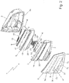
Figure 2 is a partially exploded, perspective view of the automotive lighting unit shown inFigure 1 , with parts removed for clarity; -
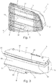
Figure 3 is a perspective view of the main lighting assembly of the automotive lighting unit shown inFigure 2 ; -
Figure 4 is an exploded perspective view of the main lighting assembly shown inFigure 3 ; -
Figure 5 is a front view of the main lighting assembly shown inFigures 3 and4 ; whereas -
Figure 6 is a side view of the lighting assembly shown inFigure 5 , cut along section line V-V. - With reference to
Figures 1 and2 ,reference numeral 1 indicates, as a whole, an automotive lighting unit particularly suited for being fixed on the rear part of the vehicle body of a car, van, truck, motorcycle or similar, i.e. a rear automotive lighting unit. - More in detail,
automotive lighting unit 1 is preferably, though not necessarily, structured so as to be stably recessed into the rear part of the vehicle body of a car or similar motor vehicle, and firstly comprises: a rigidrear casing 2, preferably made of plastic material, which is substantially basin-shaped and preferably structured so as be at least partially recessed inside a seat specially provided in the rear part of the vehicle body (not shown); and arigid front semi-shell 3, preferably made of plastic material, which is arranged to close themouth 2a of therear casing 2, preferably so as simultaneously surface on the outside of the vehicle body, and is provided with one or more transparent or semi-transparent portions, which may optionally be coloured. - In the example shown, in particular, the
rear casing 2 is preferably made of an opaque plastic material, preferably via an injection moulding process. Instead, thefront semi-shell 3 is preferably made of a transparent or semi-transparent plastic material, such as transparent or semi-transparent polycarbonate or polymethyl methacrylate for example, also in this case preferably via an injection moulding process. - Obviously, in a different embodiment, the
rear casing 2 could also be structured so as to be simply fixed on the rear part of the vehicle body (not shown). - With reference to
Figures 1 and2 , moreover theautomotive lighting unit 1 also comprises one or more electrically-powered lighting assemblies, each of which emits light on command and is located inside therear casing 2 in a position such as to backlight a corresponding transparent or semi-transparent portion of thefront semi-shell 3 separately and independently of the other lighting assemblies. - More in detail, the
automotive lighting unit 1 is provided with a main optical axis A which is parallel to the longitudinal axis of the vehicle when theautomotive lighting unit 1 is correctly positioned on the vehicle body, and each lighting assembly is adapted to project the light out of the automotive light with a prevalent component parallel to the main optical axis A. - In the example shown, in particular, the
front semi-shell 3 is preferably provided with three distinct transparent orsemi-transparent portions automotive lighting unit 1 is preferably provided with threedistinct lighting assemblies rear casing 2, directly facing a respective transparent orsemi-transparent portion semi-transparent portion - With reference to
Figures 1 and2 , preferably theautomotive lighting unit 1 moreover comprises a coveringmask 7 made of opaque material, which is located roughly at themouth 2a of thecasing 2, between thefront semi-shell 3 and thesingle lighting assemblies lighting assemblies - In the example shown, in particular, the
covering mask 7 is preferably made of an opaque plastic material, preferably via an injection moulding process, and is also preferably structured so as to directly support thesingle lighting assemblies - With reference to
Figure 2 , lighting assembly 4 preferably comprises a row of LED diodes 9 (acronym for Light Emitting Diode), which are arranged spaced out side by side to one another, preferably on asingle support board 10 that incorporates the power supply and control circuit of the diodes, and is located inside therear casing 2 preferably in a substantially horizontal position, in such a way that theLED diodes 9 can direct the generated light towards the facing transparent orsemi-transparent portion 3a of thefront semi-shell 3, so as to backlight the transparent orsemi-transparent portion 3a; and, optionally, also a plate-like screen diffuser 11 made of a transparent or semi-transparent material, which is interposed between the transparent orsemi-transparent portion 3a of thefront semi-shell 3 and the row ofLED diodes 9 so that the light emitted by theLED diodes 9 can pass through it, and is structured so as to spread the light that passes through thescreen diffuser 11 directed towards the transparent orsemi-transparent portion 3, preferably in a substantially uniform manner over the entire area/extension of the transparent orsemi-transparent portion 3a. - In the example shown, in particular, the
screen diffuser 11 is preferably made of a semi-transparent plastic material, preferably via an injection moulding process, and is preferably made in a single piece with thecovering mask 7. - With reference to
Figures 2 ,3 ,4 ,5 and 6 ,lighting assembly 5, instead, comprises: areflector body 14 which is located inside therear casing 2 spaced apart from and facing the transparent orsemi-transparent portion 3b of thefront semi-shell 3, and is provided with a reflectingsurface 14r that directly faces the transparent orsemi-transparent portion 3b and is shaped so as to reflect the incident light towards that transparent orsemi-transparent portion 3b; and a first electrically-poweredlight source 15 which is located inside therear casing 2, and is oriented so as to direct the generated light towards the reflectingsurface 14r of thereflector body 14. - Preferably, the
light source 15 is also located inside therear casing 2, on a side of the path followed by the light reflected by the reflectingsurface 14r and directed towards the transparent orsemi-transparent portion 3b of thefront semi-shell 3. - In other words, the
light source 15 is preferably located inside therear casing 2, on a side of the empty space delimited at the back by the reflectingsurface 14r of thereflector body 14 and delimited at the front by the transparent orsemi-transparent portion 3b of thefront semi-shell 3. - Preferably, the reflecting
surface 14r of thereflector body 14 is also provided with a complex three-dimensional profile, which is capable of reflecting the light coming from thelight source 15 in a predetermined manner towards specific areas/zones of the transparent orsemi-transparent portion 3b in such a way that the light generated by thelight source 15, after it has been reflected by thereflector body 14, can form/trace a first luminous pattern of predetermined shape directly on the transparent orsemi-transparent portion 3b. - In other words, the reflecting
surface 14r of thereflector body 14 is structured so as to direct the light rays r1 coming from thelight source 15 in a differentiated and prearranged manner towards a specific first sector D1 of the transparent orsemi-transparent portion 3b having a predetermined shape, so as to be able to only and exclusively backlight sector D1 of the transparent orsemi-transparent portion 3b. - More in detail, the reflecting
surface 14r of thereflector body 14 is preferably structured so as to reflect and direct the light rays r1 coming from thelight source 15 in a differentiated and prearranged manner towards sector D1 of the transparent orsemi-transparent portion 3b, so that the light rays r1 are only emitted from thefront semi-shell 3 through sector D1 of the transparent orsemi-transparent portion 3b. - Obviously, the shape of sector D1 corresponds to the shape of the first luminous pattern made on the transparent or
semi-transparent portion 3b. - With particular reference to
Figures 4 and6 , in the example shown, in particular,reflector body 14 preferably consists of a substantially basin-shaped semi-shell which is preferably made of an opaque plastic material, preferably via an injection moulding process, and is located inside therear casing 2 with the concavity turned towards the transparent orsemi-transparent portion 3b of thefront semi-shell 3. Preferably, the bottom of the substantially basin-shaped semi-shell is also mirror metalized so as form the reflectingsurface 14r. - In addition, the reflecting
surface 14r of thereflector body 14 is preferably subdivided into a multitude of small elementary reflective sectors, wherein some of the reflective sectors are opportunely shaped and oriented so as to reflect and direct the light rays r1 coming from thelight source 15 and incident on such sectors directly towards a corresponding predetermined zone/area of the transparent orsemi-transparent portion 3b of thefront semi-shell 3. Other reflective sectors are instead opportunely shaped and/or oriented so as to reflect the light rays r1 coming from thelight source 15 and incident on such sectors directly towards a dead/opaque zone of therear casing 2 and/or of thefront semi-shell 3. - The set of elementary reflective sectors is moreover as a whole structured to reflect and direct the light rays r1 coming from the
light source 15 only towards sector D1 of the transparent orsemi-transparent portion 3b, so as to be able to backlight only sector D1 of the transparent orsemi-transparent portion 3b. - Obviously, in a different embodiment, the
reflector body 14 might not have the series of reflective sectors designed to direct the light rays r1 coming from thelight source 15 towards the dead/opaque zone of therear casing 2 and/or of thefront semi-shell 3, and the reflectingsurface 14r might have a shape substantially similar that of sector D1 of the transparent orsemi-transparent portion 3b, i.e. of the first luminous pattern. - With reference to
Figures 2 ,3 ,4 ,5 and 6 , thelight source 15, instead, preferably comprises: asupport board 17 which is placed inside therear casing 2, on a side of the path followed by the light rays r1 reflected by thereflecting surface 14r and directed towards the transparent orsemi-transparent portion 3b of the front semi-shell 3 (i.e. on a side of the empty space delimited at the back by thereflector body 14 and delimited at the front by the transparent orsemi-transparent portion 3b of the front semi-shell 3); and a series of LED diodes 16 (acronym for Light Emitting Diode), which are arranged spaced out side by side to one another on a same face of thesupport board 17 in such a way that eachLED diode 16 faces the reflectingsurface 14r of thereflector body 14 and can so direct the generated light directly towards the reflectingsurface 14r. - Preferably, the
support board 17 also incorporates the power supply and control circuit for theLED diodes 16. - In the example shown, in particular, the
support board 17 is preferably located inside therear casing 2 in a substantially horizontal position and/or locally substantially perpendicular to thefront semi-shell 3. Preferably, thesupport board 17 is also arranged above thereflector body 14 and beneath thesupport board 10 of lighting assembly 4, locally substantially parallel to supportboard 10. - With reference to
Figures 2 ,3 ,4 ,5 and 6 ,lighting assembly 5 additionally further comprises: an intermediatetransparent plate 19 which is arranged in an oblique/ inclined position between the reflectingsurface 14r of thereflector body 14 and the transparent orsemi-transparent portion 3b of thefront semi-shell 3, i.e. along the path followed by the light rays r1 reflected by thereflecting surface 14r and directed towards the transparent orsemi-transparent portion 3b, so that the light reflected by thereflector body 14 towards the transparent orsemi-transparent portion 3b freely passes through it; and a second electrically-poweredlight source 20 which is located inside therear casing 2, on a side of the path followed by the light rays r1 reflected by the reflectingsurface 14r and directed towards the transparent orsemi-transparent portion 3b of the front semi-shell 3 (i.e. on a side of the empty space delimited at the back by thereflector body 14 and delimited at the front by the transparent orsemi-transparent portion 3b of the front semi-shell 3), and is oriented so as to direct the generated light towards the front face of the intermediatetransparent plate 19 in such a way that at least part of this light is reflected by the intermediatetransparent plate 19 towards the transparent orsemi-transparent portion 3b of thefront semi-shell 3. - More in detail, the
light source 20 is oriented s that at least part of the light rays r2 coming from thelight source 20 can reach the front face of the intermediatetransparent plate 19 with an angle of incidence greater than the critical angle, and so be reflected towards the transparent orsemi-transparent portion 3b of thefront semi-shell 3. - Furthermore,
light source 20 can also be activated independently oflight source 15, and is preferably located inside therear casing 2 besidelight source 15. - In addition, the
light source 20 is also preferably structured so as to create, on the front face of the intermediatetransparent plate 19, its luminous pattern of predetermined shape which the intermediatetransparent plate 19 reflects towards thefront semi-shell 3, so as to form/trace, directly on the transparent orsemi-transparent portion 3b of thefront semi-shell 3, a second luminous pattern of predetermined shape and which has a different position and/or shape from that of the first luminous pattern. - Optionally, the second luminous pattern can also be at least partially superimposed on the first luminous pattern.
- More in detail, the
light source 20 is preferably structured so as to direct, towards the intermediatetransparent plate 19, a beam of light rays r2 that strike/reach a limited zone/area of predetermined shape of the front face of the intermediatetransparent plate 19; while the intermediatetransparent plate 19 is able to reflect the light rays r2 towards thefront semi-shell 3, so as to only and exclusively backlight a second sector D2 of the transparent orsemi-transparent portion 3b not coincident with sector D1 of that transparent orsemi-transparent portion 3b. - Obviously, the shape of sector D2 corresponds to the shape of the second luminous pattern made on transparent or
semi-transparent portion 3b. Sector D2 of transparent orsemi-transparent portion 3b also has a different shape from that of sector D1 of the same transparent orsemi-transparent portion 3b. - In other words, the light rays r1 generated by
light source 15 are reflected by thereflector body 14 towards thefront semi-shell 3 so as to backlight a first sector, sector D1 in this case, of the transparent orsemi-transparent portion 3b; while the light rays r2 generated bylight source 20 are reflected by the intermediatetransparent plate 19 towards thefront semi-shell 3 so as to backlight a second sector, sector D2 in this case, of the transparent orsemi-transparent portion 3b not coincident with the first sector. - With reference to
Figures 2 ,3 ,4 ,5 and 6 , in the example shown, in particular, the intermediatetransparent plate 19 is preferably made of transparent polycarbonate or another similar plastic material, and is fastened on thereflector body 14 so as to be inclined at an angle preferably between 40° and 50° and, optionally, roughly equal to 45° with respect to the main optical axis A of the lighting unit. -
Light source 20, instead, preferably comprises a series of LED diodes 21 (acronym for Light Emitting Diode), which are arranged side by side to one another, preferably on a portion of thesupport board 17, in such a way that eachLED diode 21 faces the front face of the intermediatetransparent plate 19 and can direct the generated light towards the front face of the intermediatetransparent plate 19. - Preferably, the
light source 20 additionally also comprises a plate-like screening mask 22, which is interposed between theLED diodes 21 and the front face of the intermediatetransparent plate 19, and is provided with a large pass-through opening 22a of predetermined shape, through which part of the light emitted by theLED diodes 21 can reach the front face of the intermediatetransparent plate 19; and optionally also a plate-like screen diffuser 23 which is made of transparent or semi-transparent material, is placed to close the pass-through opening 22a of thescreening mask 22, and is structured so as to spread the light that passes through thescreen diffuser 23 directed towards the pass-through opening 22a, preferably in a substantially uniform manner over the entire area/extension of the pass-through opening 22a. - With reference to
Figures 4 ,5 and 6 , in the example shown, in particular, thescreening mask 22 preferably consists of a plate-like cover which is preferably made of an opaque plastic material and is directly fastened on thesupport board 17, completely covering the portion of the board that accommodates theLED diodes 21. - Similarly to the covering
mask 7, also plate-like cover 22 is preferably made via an injection moulding process. - The
screen diffuser 23, instead, preferably consists of a plate which is made of a semi-transparent plastic material and is preferably stably constrained between thescreening mask 22 and thesupport board 17. - With reference to
Figures 2 ,3 ,4 and6 , in addition, the transparent orsemi-transparent portion 3c of thefront semi-shell 3 is preferably contiguous/adjacent to the transparent orsemi-transparent portion 3b, and thecorresponding lighting assembly 6 is preferably arranged beside thelighting assembly 5. - Preferably,
lighting assembly 6 additionally comprises: areflector body 25 which is located inside therear casing 2 spaced apart from and facing the transparent orsemi-transparent portion 3c of thefront semi-shell 3, and is provided with a reflectingsurface 25r that directly faces the transparent orsemi-transparent portion 3c and is shaped so as to reflect the incident light towards that transparent orsemi-transparent portion 3c; and an electrically-poweredlight source 26 which is located inside therear casing 2, and is oriented so as to direct the light emitted towards the reflectingsurface 25r of thereflector body 25, so as to be able to backlight the transparent orsemi-transparent portion 3c. - Preferably, the
light source 26 is moreover arranged inside therear casing 2 on a side of the optical path between thereflector body 25 and the transparent orsemi-transparent portion 3c of thefront semi-shell 3. In other words, thelight source 26 is preferably located inside therear casing 2, on a side of the empty space delimited at the back by the reflectingsurface 25r ofreflector body 25 and delimited at the front by the transparent orsemi-transparent portion 3c offront semi-shell 3. - Preferably, the reflecting
surface 25r ofreflector body 25 is additionally provided with a complex three-dimensional profile, which is capable of reflecting the light coming fromlight source 26 in a predetermined manner towards specific areas/zones of the transparent orsemi-transparent portion 3c in such a way that the light generated by thelight source 26, after it has been reflected by thereflector body 25, can form/trace a first luminous pattern of predetermined shape directly on the transparent orsemi-transparent portion 3c. - In other words, the reflecting
surface 25r of thereflector body 25 is structured so as to direct the light rays r3 coming from thelight source 26 in a differentiated and prearranged manner towards a specific first sector D3 of the transparent orsemi-transparent portion 3c having a predetermined shape, so as to be able to only and exclusively backlight sector D3 of transparent orsemi-transparent portion 3c. - More in detail, the reflecting
surface 25r ofreflector body 25 is preferably structured so as to reflect and direct the light rays r3 coming from thelight source 26 in a differentiated and prearranged manner towards sector D3 of the transparent orsemi-transparent portion 3c, so that the light rays r3 are only emitted from thefront semi-shell 3 through sector D3 of the transparent orsemi-transparent portion 3c. - Obviously, the shape of sector D3 corresponds to the shape of the first luminous pattern realized on transparent or
semi-transparent portion 3c. - With particular reference to
Figures 4 and6 , in the example shown, in particular,reflector body 25 preferably consists of a substantially basin-shaped semi-shell, which is preferably made of an opaque plastic material, preferably via an injection moulding process, and is located inside therear casing 2 with the concavity turned towards the transparent orsemi-transparent portion 3c offront semi-shell 3. Preferably, the bottom of the substantially basin-shaped semi-shell is also mirror metalized so as form the reflectingsurface 25r. - More in detail, in the example shown, the
reflector body 25 is preferably made in a single piece with thereflector body 14. - In addition, the reflecting
surface 25r ofreflector body 25 is preferably subdivided into a multitude of small elementary reflective sectors, wherein some of the reflective sectors are opportunely shaped and oriented so as to reflect and direct the light rays r3 coming from thelight source 26 and incident on such sectors directly towards a corresponding predetermined zone/area of the transparent orsemi-transparent portion 3c of thefront semi-shell 3. Other reflective sectors are instead opportunely shaped and/or oriented so as to reflect the light rays r3 coming from thelight source 26 and incident on such sectors directly towards a dead/opaque zone of therear casing 2 and/or of thefront semi-shell 3. - Similarly to the reflecting
surface 14r, therefore the set of reflective sectors of reflectingsurface 25r is as a whole structured to reflect and direct the light rays r3 coming from thelight source 26 exclusively towards sector D3 of the transparent orsemi-transparent portion 3c, so as to be able to backlight only sector D3 of the transparent orsemi-transparent portion 3c. - Obviously, in a different embodiment, the
reflector body 25 might not have the series of reflective sectors designed to direct the light rays r3 coming from thelight source 26 towards the dead/opaque zone of therear casing 2 and/or of thefront semi-shell 3, and the reflectingsurface 25r might have a shape substantially similar that of sector D3 of the transparent orsemi-transparent portion 3c, i.e. of the first luminous pattern to create on the transparent orsemi-transparent portion 3c. - With reference to
Figures 2 and6 , instead,light source 26 preferably comprises: asupport board 27 which is arranged inside therear casing 2, on a side of the path followed by the light rays r3 reflected by the reflectingsurface 25r and directed towards the transparent orsemi-transparent portion 3c of the front semi-shell 3 (i.e. on a side of the empty space delimited at the back by thereflector body 25 and delimited at the front by the transparent orsemi-transparent portion 3c of the front semi-shell 3); and a series of LED diodes 28 (acronym for Light Emitting Diode) which are arranged spaced out side by side to one another on a same face of thesupport board 27 in such a way that eachLED diode 28 faces the reflectingsurface 25r ofreflector body 25 and can so direct the generated light directly towards the reflectingsurface 25r. - Preferably, the
support board 27 also incorporates the power supply and control circuit for theLED diodes 28. - In the example shown, in particular, the
support board 27 is preferably located inside therear casing 2 in a substantially horizontal position and/or locally substantially perpendicular to thefront semi-shell 3. Preferably, thesupport board 27 is also arranged beneath thereflector body 25, locally substantially parallel to the support board of lighting assembly 4 and thesupport board 17 oflighting assembly 5. - With reference to
Figures 2 ,3 ,4 ,5 and 6 , additionally lightingassembly 6 also comprises: an intermediatetransparent plate 29, which is arranged in an oblique/inclined position between the reflectingsurface 25r ofreflector body 25 and the transparent orsemi-transparent portion 3c offront semi-shell 3, i.e. along the path followed by the light rays r3 reflected by the reflectingsurface 25r and directed towards the transparent orsemi-transparent portion 3c, so that the light reflected by thereflector body 25 towards the transparent orsemi-transparent portion 3c passes freely through it; and a second electrically-poweredlight source 30 which is located inside therear casing 2, on a side of the path followed by the light rays r3 reflected by the reflectingsurface 25r and directed towards the transparent orsemi-transparent portion 3c of the front semi-shell 3 (i.e. on a side of the empty space delimited at the back by thereflector body 25 and delimited at the front by the transparent orsemi-transparent portion 3c of the front semi-shell 3), and is oriented so as to direct the generated light towards the front face of the intermediatetransparent plate 29 in such a way that at least part of this light is reflected by the intermediatetransparent plate 29 towards the transparent orsemi-transparent portion 3c of thefront semi-shell 3. - More in detail,
light source 30 is oriented in such a way that at least part of the light rays r4 coming from thelight source 30 can reach the front face of intermediatetransparent plate 29 with an angle of incidence greater than the critical angle, and so be reflected towards the transparent orsemi-transparent portion 3c of thefront semi-shell 3. - Furthermore,
light source 30 can also be activated independently oflight source 26, and is preferably located inside therear casing 2 besidelight source 26. - In addition,
light source 30 is also preferably structured so as to create, on the front face of the intermediatetransparent plate 9, its luminous pattern of predetermined shape which the intermediatetransparent plate 29 reflects towards thefront semi-shell 3, so as form/trace, directly on the transparent orsemi-transparent portion 3c of thefront semi-shell 3, a second luminous pattern of predetermined shape having a different position and/or shape from that of the first luminous pattern. - Optionally, the second luminous pattern realized on transparent or
semi-transparent portion 3c can also be at least partially superimposed on the first luminous pattern. - More in detail, the
light source 30 is preferably structured so as to direct, towards the intermediatetransparent plate 29, a beam of light rays r4 that strike/reach a limited zone/area of predetermined shape of the front face of intermediatetransparent plate 29; while the intermediatetransparent plate 29 is able to reflect the light rays r4 towards thefront semi-shell 3, so as to only and exclusively backlight a second sector D4 of the transparent orsemi-transparent portion 3c not coincident with sector D3 of the same transparent orsemi-transparent portion 3c. - Obviously, the shape of sector D4 corresponds to the shape of the second luminous pattern made on the transparent or
semi-transparent portion 3c. Sector D4 of transparent orsemi-transparent portion 3c also has a different shape from that of sector D3 of the same transparent orsemi-transparent portion 3c. - In other words, the light rays r3 generated by
light source 26 are reflected byreflector body 25 towards thefront semi-shell 3 so as to backlight a first sector, namely sector D3, of transparent orsemi-transparent portion 3c; while the light rays r4 generated bylight source 30 are reflected by the intermediatetransparent plate 29 towards thefront semi-shell 3 so as to backlight a second sector, sector D4 in this case, of the transparent orsemi-transparent portion 3c not coincident with the first sector. - With reference to
Figures 2 ,3 , and6 , in the example shown, in particular, the intermediatetransparent plate 29 is preferably made of transparent polycarbonate or another similar plastic material, and is fastened on thereflector body 25 so as to be inclined of an angle preferably ranging between 40° and 50° and, optionally, roughly equal to 45° with respect to the main optical axis A of the lighting unit. - Preferably, the intermediate
transparent plate 29 is moreover located inside therear casing 2 beside thetransparent plate 19, in a substantially specular position with respect to thetransparent plate 19. - More in detail, in the example shown, the
transparent plates central septum 30 that cantilevered projects from the junction between the reflectingsurfaces front semi-shell 3, locally remaining substantially perpendicular to thefront semi-shell 3 and preferably also substantially horizontal. -
Light source 30, instead, preferably comprises a series of LED diodes 32 (acronym for Light Emitting Diode), which are arranged side by side to one another, preferably on a portion of thesupport board 27, in such a way that eachLED diode 32 faces the front face of the intermediatetransparent plate 29 and can direct the generated light towards the front face of intermediatetransparent plate 29. - With reference to
Figure 6 , similar tolight source 30,light source 30 preferably also comprises: a plate-like screening mask 33 which is interposed between theLED diodes 32 and the front face of intermediatetransparent plate 29, and is provided with a large pass-through opening of predetermined shape, through which part of the light emitted by theLED diodes 32 can reach the front face of thetransparent plate 29; and optionally a plate-like screen diffuser (not shown) which is made of transparent or semi-transparent material, is placed to close the pass-through opening of thescreening mask 33, and is structured so as to spread the light that passes through the screen diffuser directed towards the pass-through opening of thescreening mask 33, preferably in a substantially uniform manner over the entire area/extension of the pass-through opening of thescreening mask 33. - Operation of
automotive lighting unit 1 is easily inferable from that described above and therefore does not need further explanation. - Instead, with regard to
lighting assemblies transparent plate 19 enables combining the light oflight source 15 with the light oflight source 20, creating two different luminous patterns onfront semi-shell 3 that may or may not be partially superimposed on one another. Similarly,transparent plate 29 enables combining the light oflight source 20 with the light oflight source 30, creating two further luminous patterns onfront semi-shell 3 that are different from each other and which may or may not be partially superimposed. - It is also possible to simulate a moving pattern by choosing the luminous pattern created by the light source 15 (or 26), the luminous pattern created by the light source 20 (or 30) and the sequence of activation of the light sources 15 (or 26) and 20 (or 30) in an appropriate manner.
- There are several advantages related to the special structure of
lighting assembly 5. - Firstly, the selective combination of the light coming from the two
light sources - Moreover
lighting assemblies 5 and/or 6 have particularly compact dimensions, thereby enabling production of a small and compactautomotive lighting unit 1. - Finally, it is clear that modifications and variants can be made to the above-described
automotive lighting unit 1 without departing from the scope of the present invention. - For example, the
lighting assembly 5 could comprise a plurality of electrically-poweredlight sources 20, each of which is oriented so as to direct the generated light towards the front face of the intermediatetransparent plate 19 in such a way that at least part of this light is reflected by the intermediatetransparent plate 19 towards the transparent orsemi-transparent portion 3b of thefront semi-shell 3 so as to form/trace a corresponding luminous pattern of predetermined shape directly on the transparent orsemi-transparent portion 3b of thefront semi-shell 3, different from that of the luminous pattern generated bylight source 15. - Furthermore, in another embodiment, instead of the
LED diodes light source semi-transparent portion front semi-shell 3.
Claims (15)
- An automotive lighting unit (1) comprising a substantially basin-shaped rear casing (2) structured for being fixed onto the vehicle body; a front semi-shell (3), which is arranged to close the mouth (2a) of the rear casing (2) and is provided with at least a first transparent or semi-transparent portion (3b); and at least a first lighting assembly (5), which emits light on command and is arranged within the rear casing (2) so as to backlight said first transparent or semi-transparent portion (3b) of the front semi-shell (3);
the automotive lighting unit (1) being characterized in that the first lighting assembly (5) comprises: a reflector body (14) which is located inside the rear casing (2) spaced apart from and facing said first transparent or semi-transparent portion (3b) and is provided with a reflecting surface (14r) designed to reflect the incident light towards said first transparent or semi-transparent portion (3b); an electrically-powered, first light source (15) which is located inside the rear casing (2) and is oriented so as to direct the generated light (r1) towards the reflecting surface (14r) of the reflector body (14) for creating a first luminous pattern (D1) of predetermined shape on said first transparent or semi-transparent portion (3b); an intermediate transparent plate (19) which is arranged in an inclined position between the reflecting surface (14r) of the reflector body (14) and said first transparent or semi-transparent portion (3b) in such a way that the light (r1) reflected by the reflector body (14) towards said first transparent or semi-transparent portion (3b) passes through it; and at least an electrically-powered, second light source (20) which is located inside the rear casing (2) and is oriented so as to direct the generated light (r2) towards the intermediate transparent plate (19) in such a way that at least part of this light (r2) is reflected by the intermediate transparent plate (19) towards said first transparent or semi-transparent portion (3b) for creating a second luminous pattern (D2) of predetermined shape on said first transparent or semi-transparent portion (3b). - Automotive lighting unit according to claim 1, characterized in that the second luminous pattern (D2) has a different position and/or shape from that of the first luminous pattern (D1).
- Automotive lighting unit according to claim 1 or 2, characterized in that the reflecting surface (14r) of the reflector body (14) is provided with a complex three-dimensional profile which is capable of reflecting the light (r1) coming from the first light source (15) in a predetermined manner towards a specific first sector (D1) of said first transparent or semi-transparent portion (3b) in such a way that the light (r1) generated by the first light source (15), after it has been reflected by the reflector body (14), can only backlight the first sector (D1) of the first transparent or semi-transparent portion (3b).
- Automotive lighting unit according to any of the preceding claims, characterized in that said first light source (16) is located inside the rear casing (2), on a side of the path followed by the light (r1) reflected by the reflecting surface (14r) of the reflector body (14) and directed towards said first transparent or semi-transparent portion (3b) of the front semi-shell (3).
- Automotive lighting unit according to claim 4, characterized in that the first light source (15) comprises: a support board (17) which is placed inside the rear casing (2), on a side of the path followed by the light (r1) reflected by the reflecting surface (14r) of the reflector body (14) and directed towards said first transparent or semi-transparent portion (3b) of the front semi-shell (3); and a first series of LED diodes (16) which are arranged on said support board (17) in such a way that each LED diode (16) faces the reflecting surface (14r) of the reflector body (14) and can direct the generated light (r1) towards said reflecting surface (14r).
- Automotive lighting unit according to any of the preceding claims, characterized in that said second light source (20) is located inside the rear casing (2), on a side of the path followed by the light (r1) reflected by the reflecting surface (14r) of the reflector body (14) and directed towards said first transparent or semi-transparent portion (3b) of the front semi-shell (3).
- Automotive lighting unit according to claim 6, characterized in that said second light source (20) is located inside the rear casing (2), beside said first light source (15).
- Automotive lighting unit according to claim 6 or 7, characterized in that said second light source (20) comprises a second series of LED diodes (21), which face the front face of said intermediate transparent plate (19) so as to direct the generated light (r2) towards said front face.
- Automotive lighting unit according to claim 8, characterized in that the LED diodes (21) of the second light source (20) are located on a portion of the support board (17) of said first light source (16).
- Automotive lighting unit according to claim 8 or 9, characterized in that said second light source (20) additionally comprises a screening mask (22) which is interposed between said second series of LED diodes (21) and the front face of the intermediate transparent plate (19), and is provided with a pass-through opening (22a) of predetermined shape through which part of the light (r2) emitted by said second series of LED diodes (21) can reach the front face of the transparent plate (19).
- Automotive lighting unit according to claim 10, characterized in that said screening mask (22) is fastened on the support board (17) of the first light source (16) to cover the portion of the board that accommodates said second series of LED diodes (21).
- Automotive lighting unit according to claim 8, 9, 10 or 11, characterized in that said second light source (20) also comprises a screen diffuser (23) which is made of transparent or semi-transparent material, is arranged to close the pass-through opening (22a) of the screening mask (22), and is structured so as to spread the light (r2) that passes through the screen diffuser (23) directed towards the pass-through opening (22a) of the screening mask (22).
- Automotive lighting unit according to any of the preceding claims, characterized in that the front semi-shell (3) is also provided with a second transparent or semi-transparent portion (3c) adjacent to said first transparent or semi-transparent portion (3b); and in that it also comprises a second lighting assembly (6) which emits light on command and is placed inside the rear casing (2), beside said first lighting assembly (5), so as to be able to backlight said second transparent or semi-transparent portion (3b) of the front semi-shell (3).
- Automotive lighting unit according to claim 13, characterized in that said second lighting assembly (6) comprises: a reflector body (25) which is located inside the rear casing (2) spaced apart from and facing said second transparent or semi-transparent portion (3c), and is provided with a reflecting surface (25r) designed to reflect the incident light towards said second transparent or semi-transparent portion (3c); an electrically-powered, first light source (26) which is located inside the rear casing (2) and is oriented so as to direct the generated light (r3) towards the reflecting surface (25r) of the reflector body (25) for creating a first luminous pattern (D3) of predetermined shape on said second transparent or semi-transparent portion (3c); an intermediate transparent plate (29) which is arranged in an inclined position between the reflecting surface (25r) of the reflector body (25) and said second transparent or semi-transparent portion (3c) so that the light (r3) reflected by the reflector body (25) towards said second transparent or semi-transparent portion (3c) passes through it; and at least an electrically-powered, second light source (30) which is located inside the rear casing (2) and is oriented so as to direct the generated light (r4) towards the intermediate transparent plate (29), in such a way that at least part of this light (r4) is reflected by the intermediate transparent plate (29) towards said second transparent or semi-transparent portion (3c) for creating a second luminous pattern (D4) of predetermined shape on said second transparent or semi-transparent portion (3c).
- Automotive lighting unit according to claim 14, characterized in that the reflector body (25) of the second lighting assembly (6) is made in one piece with the reflector body (14) of the first lighting assembly (5); and in that the intermediate transparent plate (29) of the second lighting assembly (6) is located in a substantially specular position, beside the intermediate transparent plate (19) of the first lighting assembly (5).
Priority Applications (1)
| Application Number | Priority Date | Filing Date | Title |
|---|---|---|---|
| PL17164214T PL3228928T3 (en) | 2016-03-31 | 2017-03-31 | Automotive lighting unit |
Applications Claiming Priority (1)
| Application Number | Priority Date | Filing Date | Title |
|---|---|---|---|
| ITUA2016A002153A ITUA20162153A1 (en) | 2016-03-31 | 2016-03-31 | AUTOMOTIVE HEADLIGHT |
Publications (2)
| Publication Number | Publication Date |
|---|---|
| EP3228928A1 true EP3228928A1 (en) | 2017-10-11 |
| EP3228928B1 EP3228928B1 (en) | 2020-06-17 |
Family
ID=56235937
Family Applications (1)
| Application Number | Title | Priority Date | Filing Date |
|---|---|---|---|
| EP17164214.3A Active EP3228928B1 (en) | 2016-03-31 | 2017-03-31 | Automotive lighting unit |
Country Status (4)
| Country | Link |
|---|---|
| EP (1) | EP3228928B1 (en) |
| ES (1) | ES2811308T3 (en) |
| IT (1) | ITUA20162153A1 (en) |
| PL (1) | PL3228928T3 (en) |
Cited By (1)
| Publication number | Priority date | Publication date | Assignee | Title |
|---|---|---|---|---|
| IT202100001616A1 (en) * | 2021-01-27 | 2022-07-27 | Marelli Automotive Lighting Italy Spa | AUTOMOTIVE LIGHTING AND/OR SIGNALING DEVICE |
Citations (5)
| Publication number | Priority date | Publication date | Assignee | Title |
|---|---|---|---|---|
| EP1434000A2 (en) * | 2002-12-20 | 2004-06-30 | Valeo Vision | LIghting and/or signalling device for motor vehicles |
| US20090027911A1 (en) * | 2007-07-17 | 2009-01-29 | Toyoda Gosei Co., Ltd. | Vehicular lamp |
| EP2071228A2 (en) * | 2007-12-14 | 2009-06-17 | Koito Manufacturing Co., Ltd. | Vehicle lamp assembly |
| WO2012052946A1 (en) * | 2010-10-19 | 2012-04-26 | Automotive Lighting Italia S.P.A. | Automotive light |
| KR20130039576A (en) * | 2011-10-12 | 2013-04-22 | 현대모비스 주식회사 | Lamp apparatus for vehicles |
-
2016
- 2016-03-31 IT ITUA2016A002153A patent/ITUA20162153A1/en unknown
-
2017
- 2017-03-31 ES ES17164214T patent/ES2811308T3/en active Active
- 2017-03-31 EP EP17164214.3A patent/EP3228928B1/en active Active
- 2017-03-31 PL PL17164214T patent/PL3228928T3/en unknown
Patent Citations (5)
| Publication number | Priority date | Publication date | Assignee | Title |
|---|---|---|---|---|
| EP1434000A2 (en) * | 2002-12-20 | 2004-06-30 | Valeo Vision | LIghting and/or signalling device for motor vehicles |
| US20090027911A1 (en) * | 2007-07-17 | 2009-01-29 | Toyoda Gosei Co., Ltd. | Vehicular lamp |
| EP2071228A2 (en) * | 2007-12-14 | 2009-06-17 | Koito Manufacturing Co., Ltd. | Vehicle lamp assembly |
| WO2012052946A1 (en) * | 2010-10-19 | 2012-04-26 | Automotive Lighting Italia S.P.A. | Automotive light |
| KR20130039576A (en) * | 2011-10-12 | 2013-04-22 | 현대모비스 주식회사 | Lamp apparatus for vehicles |
Cited By (2)
| Publication number | Priority date | Publication date | Assignee | Title |
|---|---|---|---|---|
| IT202100001616A1 (en) * | 2021-01-27 | 2022-07-27 | Marelli Automotive Lighting Italy Spa | AUTOMOTIVE LIGHTING AND/OR SIGNALING DEVICE |
| EP4035941A1 (en) * | 2021-01-27 | 2022-08-03 | Marelli Automotive Lighting Italy S.p.A. | Automotive lighting and/or signalling device |
Also Published As
| Publication number | Publication date |
|---|---|
| ES2811308T3 (en) | 2021-03-11 |
| PL3228928T3 (en) | 2021-02-08 |
| EP3228928B1 (en) | 2020-06-17 |
| ITUA20162153A1 (en) | 2017-10-01 |
Similar Documents
| Publication | Publication Date | Title |
|---|---|---|
| US10415792B2 (en) | Light guiding device | |
| CN106066020B (en) | Automobile lamp | |
| EP3009734B1 (en) | Automotive light | |
| US10859230B2 (en) | Automotive lighting unit with a light guide plate | |
| EP3009300B1 (en) | Automotive light | |
| CN107107815B (en) | Additional brake light for vehicle | |
| JP4930787B2 (en) | VEHICLE LIGHT AND LIGHT GUIDE LENS USED FOR VEHICLE LIGHT | |
| US10808906B2 (en) | Method for obtaining a luminous device the turned-off aspect of which is different from the turned-on aspect | |
| EP3009301B1 (en) | Automotive light | |
| JP2020059445A (en) | Optical device for vehicle | |
| CN210069733U (en) | Optical system for car lamp and tail lamp | |
| CN210069734U (en) | Optical system for car lamp and tail lamp | |
| JP2019145483A (en) | Illumination and/or signal device for automobile having divided illumination part | |
| US11280468B2 (en) | Hidden light apparatus of grill for vehicle | |
| JP7145644B2 (en) | vehicle lamp | |
| EP3228928B1 (en) | Automotive lighting unit | |
| JP2015008111A (en) | Composite lamp unit using linear light guide body, and vehicular lighting device | |
| EP3819535A1 (en) | Illumination device for a vehicle interiors | |
| JP7223532B2 (en) | Light-emitting devices for road lighting, signaling or interior lighting | |
| EP4023935A1 (en) | Automotive light | |
| EP4296564A1 (en) | Automotive light | |
| JP7383926B2 (en) | Vehicle lights | |
| CN108626691B (en) | Rear combined lamp capable of realizing uniform light emission through light guide of two-way side light | |
| JP2018195380A (en) | Vehicular lighting fixture |
Legal Events
| Date | Code | Title | Description |
|---|---|---|---|
| PUAI | Public reference made under article 153(3) epc to a published international application that has entered the european phase |
Free format text: ORIGINAL CODE: 0009012 |
|
| STAA | Information on the status of an ep patent application or granted ep patent |
Free format text: STATUS: THE APPLICATION HAS BEEN PUBLISHED |
|
| AK | Designated contracting states |
Kind code of ref document: A1 Designated state(s): AL AT BE BG CH CY CZ DE DK EE ES FI FR GB GR HR HU IE IS IT LI LT LU LV MC MK MT NL NO PL PT RO RS SE SI SK SM TR |
|
| AX | Request for extension of the european patent |
Extension state: BA ME |
|
| STAA | Information on the status of an ep patent application or granted ep patent |
Free format text: STATUS: REQUEST FOR EXAMINATION WAS MADE |
|
| 17P | Request for examination filed |
Effective date: 20180410 |
|
| RBV | Designated contracting states (corrected) |
Designated state(s): AL AT BE BG CH CY CZ DE DK EE ES FI FR GB GR HR HU IE IS IT LI LT LU LV MC MK MT NL NO PL PT RO RS SE SI SK SM TR |
|
| REG | Reference to a national code |
Ref country code: DE Ref legal event code: R079 Ref document number: 602017018146 Country of ref document: DE Free format text: PREVIOUS MAIN CLASS: F21S0008100000 Ipc: F21S0043400000 |
|
| GRAP | Despatch of communication of intention to grant a patent |
Free format text: ORIGINAL CODE: EPIDOSNIGR1 |
|
| STAA | Information on the status of an ep patent application or granted ep patent |
Free format text: STATUS: GRANT OF PATENT IS INTENDED |
|
| RIC1 | Information provided on ipc code assigned before grant |
Ipc: F21S 43/14 20180101ALI20191210BHEP Ipc: F21S 43/40 20180101AFI20191210BHEP Ipc: F21S 43/31 20180101ALI20191210BHEP |
|
| INTG | Intention to grant announced |
Effective date: 20200103 |
|
| GRAS | Grant fee paid |
Free format text: ORIGINAL CODE: EPIDOSNIGR3 |
|
| GRAA | (expected) grant |
Free format text: ORIGINAL CODE: 0009210 |
|
| STAA | Information on the status of an ep patent application or granted ep patent |
Free format text: STATUS: THE PATENT HAS BEEN GRANTED |
|
| RAP1 | Party data changed (applicant data changed or rights of an application transferred) |
Owner name: MARELLI AUTOMOTIVE LIGHTING ITALY S.P.A. |
|
| AK | Designated contracting states |
Kind code of ref document: B1 Designated state(s): AL AT BE BG CH CY CZ DE DK EE ES FI FR GB GR HR HU IE IS IT LI LT LU LV MC MK MT NL NO PL PT RO RS SE SI SK SM TR |
|
| REG | Reference to a national code |
Ref country code: GB Ref legal event code: FG4D |
|
| REG | Reference to a national code |
Ref country code: CH Ref legal event code: EP |
|
| REG | Reference to a national code |
Ref country code: DE Ref legal event code: R096 Ref document number: 602017018146 Country of ref document: DE |
|
| REG | Reference to a national code |
Ref country code: IE Ref legal event code: FG4D |
|
| REG | Reference to a national code |
Ref country code: AT Ref legal event code: REF Ref document number: 1281751 Country of ref document: AT Kind code of ref document: T Effective date: 20200715 |
|
| PG25 | Lapsed in a contracting state [announced via postgrant information from national office to epo] |
Ref country code: GR Free format text: LAPSE BECAUSE OF FAILURE TO SUBMIT A TRANSLATION OF THE DESCRIPTION OR TO PAY THE FEE WITHIN THE PRESCRIBED TIME-LIMIT Effective date: 20200918 Ref country code: LT Free format text: LAPSE BECAUSE OF FAILURE TO SUBMIT A TRANSLATION OF THE DESCRIPTION OR TO PAY THE FEE WITHIN THE PRESCRIBED TIME-LIMIT Effective date: 20200617 Ref country code: NO Free format text: LAPSE BECAUSE OF FAILURE TO SUBMIT A TRANSLATION OF THE DESCRIPTION OR TO PAY THE FEE WITHIN THE PRESCRIBED TIME-LIMIT Effective date: 20200917 Ref country code: SE Free format text: LAPSE BECAUSE OF FAILURE TO SUBMIT A TRANSLATION OF THE DESCRIPTION OR TO PAY THE FEE WITHIN THE PRESCRIBED TIME-LIMIT Effective date: 20200617 Ref country code: FI Free format text: LAPSE BECAUSE OF FAILURE TO SUBMIT A TRANSLATION OF THE DESCRIPTION OR TO PAY THE FEE WITHIN THE PRESCRIBED TIME-LIMIT Effective date: 20200617 |
|
| REG | Reference to a national code |
Ref country code: LT Ref legal event code: MG4D |
|
| REG | Reference to a national code |
Ref country code: NL Ref legal event code: MP Effective date: 20200617 |
|
| PG25 | Lapsed in a contracting state [announced via postgrant information from national office to epo] |
Ref country code: LV Free format text: LAPSE BECAUSE OF FAILURE TO SUBMIT A TRANSLATION OF THE DESCRIPTION OR TO PAY THE FEE WITHIN THE PRESCRIBED TIME-LIMIT Effective date: 20200617 Ref country code: HR Free format text: LAPSE BECAUSE OF FAILURE TO SUBMIT A TRANSLATION OF THE DESCRIPTION OR TO PAY THE FEE WITHIN THE PRESCRIBED TIME-LIMIT Effective date: 20200617 Ref country code: BG Free format text: LAPSE BECAUSE OF FAILURE TO SUBMIT A TRANSLATION OF THE DESCRIPTION OR TO PAY THE FEE WITHIN THE PRESCRIBED TIME-LIMIT Effective date: 20200917 Ref country code: RS Free format text: LAPSE BECAUSE OF FAILURE TO SUBMIT A TRANSLATION OF THE DESCRIPTION OR TO PAY THE FEE WITHIN THE PRESCRIBED TIME-LIMIT Effective date: 20200617 |
|
| REG | Reference to a national code |
Ref country code: AT Ref legal event code: MK05 Ref document number: 1281751 Country of ref document: AT Kind code of ref document: T Effective date: 20200617 |
|
| PG25 | Lapsed in a contracting state [announced via postgrant information from national office to epo] |
Ref country code: AL Free format text: LAPSE BECAUSE OF FAILURE TO SUBMIT A TRANSLATION OF THE DESCRIPTION OR TO PAY THE FEE WITHIN THE PRESCRIBED TIME-LIMIT Effective date: 20200617 Ref country code: NL Free format text: LAPSE BECAUSE OF FAILURE TO SUBMIT A TRANSLATION OF THE DESCRIPTION OR TO PAY THE FEE WITHIN THE PRESCRIBED TIME-LIMIT Effective date: 20200617 |
|
| PG25 | Lapsed in a contracting state [announced via postgrant information from national office to epo] |
Ref country code: RO Free format text: LAPSE BECAUSE OF FAILURE TO SUBMIT A TRANSLATION OF THE DESCRIPTION OR TO PAY THE FEE WITHIN THE PRESCRIBED TIME-LIMIT Effective date: 20200617 Ref country code: PT Free format text: LAPSE BECAUSE OF FAILURE TO SUBMIT A TRANSLATION OF THE DESCRIPTION OR TO PAY THE FEE WITHIN THE PRESCRIBED TIME-LIMIT Effective date: 20201019 Ref country code: EE Free format text: LAPSE BECAUSE OF FAILURE TO SUBMIT A TRANSLATION OF THE DESCRIPTION OR TO PAY THE FEE WITHIN THE PRESCRIBED TIME-LIMIT Effective date: 20200617 Ref country code: SM Free format text: LAPSE BECAUSE OF FAILURE TO SUBMIT A TRANSLATION OF THE DESCRIPTION OR TO PAY THE FEE WITHIN THE PRESCRIBED TIME-LIMIT Effective date: 20200617 Ref country code: AT Free format text: LAPSE BECAUSE OF FAILURE TO SUBMIT A TRANSLATION OF THE DESCRIPTION OR TO PAY THE FEE WITHIN THE PRESCRIBED TIME-LIMIT Effective date: 20200617 |
|
| PG25 | Lapsed in a contracting state [announced via postgrant information from national office to epo] |
Ref country code: SK Free format text: LAPSE BECAUSE OF FAILURE TO SUBMIT A TRANSLATION OF THE DESCRIPTION OR TO PAY THE FEE WITHIN THE PRESCRIBED TIME-LIMIT Effective date: 20200617 Ref country code: IS Free format text: LAPSE BECAUSE OF FAILURE TO SUBMIT A TRANSLATION OF THE DESCRIPTION OR TO PAY THE FEE WITHIN THE PRESCRIBED TIME-LIMIT Effective date: 20201017 |
|
| REG | Reference to a national code |
Ref country code: ES Ref legal event code: FG2A Ref document number: 2811308 Country of ref document: ES Kind code of ref document: T3 Effective date: 20210311 |
|
| REG | Reference to a national code |
Ref country code: DE Ref legal event code: R097 Ref document number: 602017018146 Country of ref document: DE |
|
| PLBE | No opposition filed within time limit |
Free format text: ORIGINAL CODE: 0009261 |
|
| STAA | Information on the status of an ep patent application or granted ep patent |
Free format text: STATUS: NO OPPOSITION FILED WITHIN TIME LIMIT |
|
| PG25 | Lapsed in a contracting state [announced via postgrant information from national office to epo] |
Ref country code: DK Free format text: LAPSE BECAUSE OF FAILURE TO SUBMIT A TRANSLATION OF THE DESCRIPTION OR TO PAY THE FEE WITHIN THE PRESCRIBED TIME-LIMIT Effective date: 20200617 |
|
| 26N | No opposition filed |
Effective date: 20210318 |
|
| PG25 | Lapsed in a contracting state [announced via postgrant information from national office to epo] |
Ref country code: SI Free format text: LAPSE BECAUSE OF FAILURE TO SUBMIT A TRANSLATION OF THE DESCRIPTION OR TO PAY THE FEE WITHIN THE PRESCRIBED TIME-LIMIT Effective date: 20200617 |
|
| PG25 | Lapsed in a contracting state [announced via postgrant information from national office to epo] |
Ref country code: MC Free format text: LAPSE BECAUSE OF FAILURE TO SUBMIT A TRANSLATION OF THE DESCRIPTION OR TO PAY THE FEE WITHIN THE PRESCRIBED TIME-LIMIT Effective date: 20200617 |
|
| REG | Reference to a national code |
Ref country code: CH Ref legal event code: PL |
|
| REG | Reference to a national code |
Ref country code: BE Ref legal event code: MM Effective date: 20210331 |
|
| PG25 | Lapsed in a contracting state [announced via postgrant information from national office to epo] |
Ref country code: IE Free format text: LAPSE BECAUSE OF NON-PAYMENT OF DUE FEES Effective date: 20210331 Ref country code: LU Free format text: LAPSE BECAUSE OF NON-PAYMENT OF DUE FEES Effective date: 20210331 Ref country code: LI Free format text: LAPSE BECAUSE OF NON-PAYMENT OF DUE FEES Effective date: 20210331 Ref country code: CH Free format text: LAPSE BECAUSE OF NON-PAYMENT OF DUE FEES Effective date: 20210331 |
|
| PG25 | Lapsed in a contracting state [announced via postgrant information from national office to epo] |
Ref country code: BE Free format text: LAPSE BECAUSE OF NON-PAYMENT OF DUE FEES Effective date: 20210331 |
|
| PGFP | Annual fee paid to national office [announced via postgrant information from national office to epo] |
Ref country code: FR Payment date: 20230222 Year of fee payment: 7 Ref country code: CZ Payment date: 20230224 Year of fee payment: 7 |
|
| PG25 | Lapsed in a contracting state [announced via postgrant information from national office to epo] |
Ref country code: HU Free format text: LAPSE BECAUSE OF FAILURE TO SUBMIT A TRANSLATION OF THE DESCRIPTION OR TO PAY THE FEE WITHIN THE PRESCRIBED TIME-LIMIT; INVALID AB INITIO Effective date: 20170331 |
|
| PGFP | Annual fee paid to national office [announced via postgrant information from national office to epo] |
Ref country code: TR Payment date: 20230228 Year of fee payment: 7 Ref country code: PL Payment date: 20230224 Year of fee payment: 7 Ref country code: IT Payment date: 20230221 Year of fee payment: 7 |
|
| PG25 | Lapsed in a contracting state [announced via postgrant information from national office to epo] |
Ref country code: CY Free format text: LAPSE BECAUSE OF FAILURE TO SUBMIT A TRANSLATION OF THE DESCRIPTION OR TO PAY THE FEE WITHIN THE PRESCRIBED TIME-LIMIT Effective date: 20200617 |
|
| PGFP | Annual fee paid to national office [announced via postgrant information from national office to epo] |
Ref country code: ES Payment date: 20230403 Year of fee payment: 7 |
|
| PG25 | Lapsed in a contracting state [announced via postgrant information from national office to epo] |
Ref country code: MK Free format text: LAPSE BECAUSE OF FAILURE TO SUBMIT A TRANSLATION OF THE DESCRIPTION OR TO PAY THE FEE WITHIN THE PRESCRIBED TIME-LIMIT Effective date: 20200617 |
|
| PGFP | Annual fee paid to national office [announced via postgrant information from national office to epo] |
Ref country code: DE Payment date: 20240220 Year of fee payment: 8 Ref country code: CZ Payment date: 20240226 Year of fee payment: 8 Ref country code: GB Payment date: 20240221 Year of fee payment: 8 |