EP4035937A1 - Dump truck - Google Patents
Dump truck Download PDFInfo
- Publication number
- EP4035937A1 EP4035937A1 EP20869786.2A EP20869786A EP4035937A1 EP 4035937 A1 EP4035937 A1 EP 4035937A1 EP 20869786 A EP20869786 A EP 20869786A EP 4035937 A1 EP4035937 A1 EP 4035937A1
- Authority
- EP
- European Patent Office
- Prior art keywords
- front wheel
- solenoid valve
- rear wheel
- dump truck
- controller
- Prior art date
- Legal status (The legal status is an assumption and is not a legal conclusion. Google has not performed a legal analysis and makes no representation as to the accuracy of the status listed.)
- Pending
Links
Images


Classifications
-
- B—PERFORMING OPERATIONS; TRANSPORTING
- B60—VEHICLES IN GENERAL
- B60T—VEHICLE BRAKE CONTROL SYSTEMS OR PARTS THEREOF; BRAKE CONTROL SYSTEMS OR PARTS THEREOF, IN GENERAL; ARRANGEMENT OF BRAKING ELEMENTS ON VEHICLES IN GENERAL; PORTABLE DEVICES FOR PREVENTING UNWANTED MOVEMENT OF VEHICLES; VEHICLE MODIFICATIONS TO FACILITATE COOLING OF BRAKES
- B60T17/00—Component parts, details, or accessories of power brake systems not covered by groups B60T8/00, B60T13/00 or B60T15/00, or presenting other characteristic features
- B60T17/18—Safety devices; Monitoring
- B60T17/22—Devices for monitoring or checking brake systems; Signal devices
-
- B—PERFORMING OPERATIONS; TRANSPORTING
- B60—VEHICLES IN GENERAL
- B60P—VEHICLES ADAPTED FOR LOAD TRANSPORTATION OR TO TRANSPORT, TO CARRY, OR TO COMPRISE SPECIAL LOADS OR OBJECTS
- B60P1/00—Vehicles predominantly for transporting loads and modified to facilitate loading, consolidating the load, or unloading
- B60P1/04—Vehicles predominantly for transporting loads and modified to facilitate loading, consolidating the load, or unloading with a tipping movement of load-transporting element
-
- B—PERFORMING OPERATIONS; TRANSPORTING
- B60—VEHICLES IN GENERAL
- B60T—VEHICLE BRAKE CONTROL SYSTEMS OR PARTS THEREOF; BRAKE CONTROL SYSTEMS OR PARTS THEREOF, IN GENERAL; ARRANGEMENT OF BRAKING ELEMENTS ON VEHICLES IN GENERAL; PORTABLE DEVICES FOR PREVENTING UNWANTED MOVEMENT OF VEHICLES; VEHICLE MODIFICATIONS TO FACILITATE COOLING OF BRAKES
- B60T13/00—Transmitting braking action from initiating means to ultimate brake actuator with power assistance or drive; Brake systems incorporating such transmitting means, e.g. air-pressure brake systems
- B60T13/10—Transmitting braking action from initiating means to ultimate brake actuator with power assistance or drive; Brake systems incorporating such transmitting means, e.g. air-pressure brake systems with fluid assistance, drive, or release
- B60T13/12—Transmitting braking action from initiating means to ultimate brake actuator with power assistance or drive; Brake systems incorporating such transmitting means, e.g. air-pressure brake systems with fluid assistance, drive, or release the fluid being liquid
- B60T13/14—Transmitting braking action from initiating means to ultimate brake actuator with power assistance or drive; Brake systems incorporating such transmitting means, e.g. air-pressure brake systems with fluid assistance, drive, or release the fluid being liquid using accumulators or reservoirs fed by pumps
-
- B—PERFORMING OPERATIONS; TRANSPORTING
- B60—VEHICLES IN GENERAL
- B60T—VEHICLE BRAKE CONTROL SYSTEMS OR PARTS THEREOF; BRAKE CONTROL SYSTEMS OR PARTS THEREOF, IN GENERAL; ARRANGEMENT OF BRAKING ELEMENTS ON VEHICLES IN GENERAL; PORTABLE DEVICES FOR PREVENTING UNWANTED MOVEMENT OF VEHICLES; VEHICLE MODIFICATIONS TO FACILITATE COOLING OF BRAKES
- B60T2230/00—Monitoring, detecting special vehicle behaviour; Counteracting thereof
-
- B—PERFORMING OPERATIONS; TRANSPORTING
- B60—VEHICLES IN GENERAL
- B60T—VEHICLE BRAKE CONTROL SYSTEMS OR PARTS THEREOF; BRAKE CONTROL SYSTEMS OR PARTS THEREOF, IN GENERAL; ARRANGEMENT OF BRAKING ELEMENTS ON VEHICLES IN GENERAL; PORTABLE DEVICES FOR PREVENTING UNWANTED MOVEMENT OF VEHICLES; VEHICLE MODIFICATIONS TO FACILITATE COOLING OF BRAKES
- B60T2270/00—Further aspects of brake control systems not otherwise provided for
- B60T2270/40—Failsafe aspects of brake control systems
Definitions
- the present invention relates to a dump truck equipped with an emergency brake system.
- An autonomous dump truck is equipped with an emergency brake system that brakes wheels in an emergency.
- the emergency brake system is configured to, for example, open a solenoid valve to supply a hydraulic brake device with hydraulic oil accumulated in an accumulator.
- Patent Literature 1 discloses a dump truck in which a parking brake is actuated when a vehicle body is stopped so as to prevent sticking of the solenoid valve.
- Patent Literature 1 JP-B-5838255
- the first problem is that, if a loading operation is performed in a state where both the front and rear emergency brake systems are actuated, excessive impact is imposed on a vehicle body.
- the second problem is that, when both the front and rear emergency brake systems are released at the same time, the vehicle body may overrun due to impact and inertial force during the loading operation.
- the present invention has been made in view of the circumstances above, and thus an object of the present invention is to provide a dump truck capable of performing an actuation test of an emergency brake system at an appropriate timing.
- the present invention provides a dump truck comprising: a vehicle body frame that rotatably supports front wheels and rear wheels through suspensions; a vessel that is supported on the vehicle body frame so as to be able to rise and fall between a rising position and a fallen position; a strut pressure sensor that is configured to detect pressure applied to the suspensions; a hydraulic pump that transfers hydraulic oil; a front wheel emergency brake system and a rear wheel emergency brake system that are configured to brake the front wheels and the rear wheels, respectively; and a controller that is configured to control operations of the front wheel emergency brake system and the rear wheel emergency brake system, wherein the front wheel emergency brake system and the rear wheel emergency brake system include, respectively: a front wheel accumulator and a rear wheel accumulator that are configured to accumulate the hydraulic oil supplied from the hydraulic pump; a front wheel brake device and a rear wheel brake device that are configured to be actuated by the hydraulic oil supplied from the front wheel accumulator and the rear wheel accumulator, respectively; and a front wheel solenoid valve and
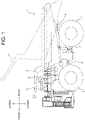
- FIG. 1 is a side view of a dump truck 1 according to the present embodiment.
- the front, rear, left, and right directions are referred based on a viewpoint of an operator who is in the dump truck 1 to operate the dump truck 1, unless otherwise noted.
- the dump truck 1 mainly includes a vehicle body frame 2, a pair of front wheels 3 that is rotatably supported through a suspension 3S at both left and right ends of a front portion of the vehicle body frame 2, a pair of rear wheels 4 that is rotatably supported through a suspension 4S at both left and right ends of a rear portion of the vehicle body frame 2, a vessel 5 that is supported on the vehicle body frame 2 so as to be able to rise and fall, and a cab 6 to be boarded by an operator who operates the dump truck 1.
- Each of the pair of front wheels 3 is a steering wheel whose steering angle changes in response to a steering operation.
- Each of the pair of rear wheels 4 is a drive wheel that is rotated by drive force transmitted from traveling motors 54R, 54L (see FIG. 3 ).
- the dump truck 1 includes a pair of traveling motors 54R, 54L in order to transmit the drive force independently to each of the pair of rear wheels 4.
- the dump truck 1 includes suspension sensors (strut pressure sensors) 51R, 51L, 52R, 52L (see FIG. 3 ) configured to detect pressure (hereinafter, referred to as "strut pressure") applied to the suspensions 3S, 4S for supporting the pair of front wheels 3 and the pair of rear wheels 4, respectively, and output detection signals indicating detection results to a controller 40 (see FIG. 3 ).
- the suspension sensor 51R detects the pressure applied to the suspension of the right front wheel 3
- the suspension sensor 51L detects the pressure applied to the suspension of the left front wheel 3
- the suspension sensor 52R detects the pressure applied to the suspension of the right rear wheel 4
- the suspension sensor 52L detects the pressure applied to the suspension of the left rear wheel 4.
- the traveling motors 54R, 54L are equipped with vehicle speed sensors 55R, 55L (see FIG. 3 ).
- Each of the vehicle speed sensors 55R, 55L is configured to detect vehicle speed as traveling speed of the dump truck 1, and output a vehicle speed signal indicating a detection result to the controller 40.
- each of the vehicle speed sensors 55R, 55L may be configured to detect, as the traveling speed of the dump truck 1, rotational speed of the traveling motors 54R, 54L, respectively.
- a Hall element that makes use of Hall effect to detect a magnetic field can be employed.
- the vessel 5 rises and falls in the vertical direction by expansion and contraction of a hoist cylinder 7.
- the vessel 5 is configured such that it can rise and fall between a fallen position illustrated by solid lines in FIG. 1 and a rising position illustrated by broken lines in FIG. 1 .
- the fallen position is a position of the vessel 5 at the time when the hoist cylinder 7 is contracted. In the fallen position, the vessel 5 can be loaded with earth and sand from such as a hydraulic excavator.
- the rising position is a position of the vessel 5 at the time when the hoist cylinder 7 is expanded. By rotating the vessel 5 from the fallen position to the rising position, the earth and sand loaded onto the vessel 5 is discharged.
- the dump truck 1 includes an angle sensor 53 configured to detect an angle of the vessel 5 with respect to a reference position (for example, the fallen position), and output a detection signal indicating a detection result to the controller 40 (see FIG. 3 ).
- the cab 6 is arranged on the left end of a deck 9 on the front end of the vehicle frame 2.
- the cab 6 serves as an operator's cab to be boarded by the operator who operates the dump truck 1.
- operation devices accelerator pedal, brake pedal, hoist pedal, steering, lever, switch, etc.
- the operator in the cab 6 operates the operation devices, whereby the dump truck 1 travels (is accelerated or braked) and the vessel 5 rises.
- FIG. 2 illustrates a circuit of a hydraulic brake system 10 equipped on the dump truck 1.
- the hydraulic brake system 10 is configured to brake the front and rear wheels 3, 4 by means of hydraulic oil transferred from the hydraulic pump 11.
- the hydraulic pump 11 is rotated by drive force transmitted from an engine (not illustrated), thereby transferring the hydraulic oil stored in a hydraulic oil tank 37.
- the hydraulic brake system 10 mainly includes a foot brake system 12, a front wheel emergency brake system 13, a rear wheel emergency brake system 14, and a load dump brake (auxiliary brake) 15.
- the foot brake system 12 is configured to brake the front and rear wheels 3, 4 in accordance with a stepping-on operation of a brake pedal performed by the operator in the cab 6.
- the foot brake system 12 mainly includes accumulators 16, 17 and check valves 18, 19.
- Each of the accumulators 16, 17 accumulates the hydraulic oil supplied from the hydraulic pump 11 through each of the check valves 18, 19.
- a front wheel brake device 21 is supplied with the hydraulic oil accumulated in the accumulator 16 through a shuttle valve 20 while a rear wheel brake device 24 is supplied with the hydraulic oil accumulated in the accumulator 17 through shuttle valves 22, 23.
- Each of the front wheel brake device 21 and the rear wheel brake device 24 is supplied with the hydraulic oil, thereby braking the front wheels 3 and rear wheels 4.
- the braking force from the front wheel brake device 21 and the rear wheel brake device 24 increases as the stepping-on amount of the brake pedal increases.
- the operator stops stepping on the brake pedal the braking of the wheels performed by the front wheel brake device 21 and the rear wheel brake device 24 is released.
- the front wheel emergency brake system 13 is configured to brake the front wheels 3 in response to control by the controller 40.
- the front wheel emergency brake system 13 mainly includes a front wheel accumulator 25, a check valve 26, a front wheel solenoid valve 27, and a pressure sensor 28.
- the front wheel emergency brake system 13 is a so-called "negative brake", which is configured to release the braking of the front wheels 3 only while the control voltage is applied to the front wheel solenoid valve 27 by the controller 40.
- the front wheel accumulator 25 accumulates the hydraulic oil supplied from the hydraulic pump 11 through the check valve 26.
- the front wheel solenoid valve 27 is configured to open and close a flow path of the hydraulic oil extending from the front wheel accumulator 25 to the front wheel brake device 21 in response to control of the controller 40.
- the pressure sensor 28 is configured to detect pressure of the hydraulic oil output from the front wheel accumulator 25 (primary pressure of the front wheel solenoid valve 27), and output a detection signal indicating a detection result to the controller 40.
- the front wheel solenoid valve 27 When no control voltage is applied to the front wheel solenoid valve 27 by the controller 40, the front wheel solenoid valve 27 opens the flow path. Thus, the front wheel brake device 21 is supplied with the hydraulic oil from the front wheel accumulator 25 through the shuttle valve 20, whereby the front wheels 3 are braked by the front wheel emergency brake system 13. On the other hand, when the control voltage is applied to the front wheel solenoid valve 27 by the controller 40, the front wheel solenoid valve 27 closes the flow path extending from the front wheel accumulator 25 to the front wheel brake device 21 so as to communicate the front wheel brake device 21 to the hydraulic oil tank 37.
- the front wheel brake device 21 is not supplied with the hydraulic oil from the front wheel accumulator 25, and the hydraulic oil is refluxed from the front wheel brake device 21 to the hydraulic oil tank 37. As a result, the braking of the front wheels 3 that has been performed by the front wheel emergency brake system 13 is released.
- the rear wheel emergency brake system 14 is configured to brake the rear wheels4 in response to control by the controller 40.
- the rear wheel emergency brake system 14 mainly includes a rear wheel accumulator 29, a check valve 30, a rear wheel solenoid valve 31, and a pressure sensor 32.
- the rear wheel emergency brake system 14 is a so-called "negative brake", which is configured to release the braking of the rear wheels 4 only while the control voltage is applied to the rear wheel solenoid valve 31 by the controller 40.
- the rear wheel accumulator 29 accumulates the hydraulic oil supplied from the hydraulic pump 11 through the check valve 30.
- the rear wheel solenoid valve 31 is configured to open and close a flow path of the hydraulic oil extending from the rear wheel accumulator 29 to the rear wheel brake device 24 in response to control of the controller 40.
- the pressure sensor 32 is configured to detect pressure of the hydraulic oil output from the rear wheel accumulator 29 (primary pressure of the rear wheel solenoid valve 31), and output a detection signal indicating a detection result to the controller 40.
- the rear wheel solenoid valve 31 When no control voltage is applied to the rear wheel solenoid valve 31 by the controller 40, the rear wheel solenoid valve 31 opens the flow path. Thus, the rear wheel brake device 24 is supplied with the hydraulic oil from the rear wheel accumulator 29 through the shuttle valves 22, 23, whereby the rear wheels 4 are braked by the rear wheel emergency brake system 14. On the other hand, when the control voltage is applied to the rear wheel solenoid valve 31 by the controller 40, the rear wheel solenoid valve 31 closes the flow path extending from the rear wheel accumulator 29 to the rear wheel brake device 24 so as to communicate the rear wheel brake device 24 to the hydraulic oil tank 37.
- the rear wheel brake device 24 is not supplied with the hydraulic oil from the rear wheel accumulator 29, and the hydraulic oil is refluxed from the rear wheel brake device 24 to the hydraulic oil tank 37. As a result, the braking of the rear wheels 4 that has been performed by the rear wheel emergency brake system 14 is released.
- the load dump brake 15 is configured to lock the rear wheels 4 in response to control by the controller 40.
- the operator operates the load dump brake 15 so as to prevent the vehicle from moving, for example, at the time of loading earth and sand onto the vessel 5 or discharging the earth and sand of the vessel 5.
- the load dump brake 15 mainly includes an accumulator 33 and a load dump brake solenoid valve 34.
- the accumulator 33 accumulates the hydraulic oil supplied from the hydraulic pump 11.
- the load dump brake solenoid valve 34 is configured to open and close a flow path of the hydraulic oil extending from the accumulator 33 to the rear wheel brake device 24 in response to the control by the controller 40.
- the load dump brake solenoid valve 34 When the control voltage is applied to the load dump brake solenoid valve 34 by the controller 40, the load dump brake solenoid valve 34 opens the flow path. Thus, the rear wheel brake device 24 is supplied with the hydraulic oil from the accumulator 33 through the shuttle valve 23, whereby the rear wheels 4 are braked by the load dump brake 15.
- the load dump brake solenoid valve 34 closes the flow path extending from the accumulator 33 to the rear wheel brake device 24 so as to communicate the rear wheel brake device 24 to the hydraulic oil tank 37.
- the rear wheel brake device 24 is not supplied with the hydraulic oil from the accumulator 33, and the hydraulic oil is refluxed from the rear wheel brake device 24 to the hydraulic oil tank 37. As a result, the braking of the rear wheels 4 that has been performed by the load dump brake 15 is released.
- the front wheel brake device 21 is commonly used in the foot brake system 12 and the front wheel emergency brake system 13.
- the rear wheel brake device 24 is commonly used in the foot brake system 12, the rear wheel emergency brake system 14, and the load dump brake 15.
- the front wheel brake device 21 is a disc type brake while the rear wheel brake device 24 is a wet type multiplate brake.
- the hydraulic brake system 10 further includes a pressure sensor 35 configured to detect pressure of the hydraulic oil supplied to the front wheel brake device 21, and output a detection signal indicating a detection result to the controller 40.
- the pressure sensor 35 detects the secondary pressure of the front wheel solenoid valve 27 while the front wheel emergency brake system 13 is in operation.
- the hydraulic brake system 10 further includes a pressure sensor 36 configured to detect pressure of the hydraulic oil supplied to the rear wheel brake device 24, and output a detection signal indicating a detection result to the controller 40.
- the pressure sensor 36 detects the secondary pressure of the rear wheel solenoid valve 31 while the rear wheel emergency brake system 14 is in operation.
- the pressure sensor 36 detects the secondary pressure of the load dump brake solenoid valve 34 while the load dump brake 15 is in operation.
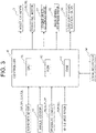
- FIG. 3 is a block diagram of the controller 40 equipped on the dump truck 1.
- the controller 40 is configured to control the hoist cylinder 7, the traveling motors 54R, 54L, and the solenoid valves 27, 31, 34 based on the detection signals output from the suspension sensors 51R, 51L, 52R, 52L, the angle sensor 53, and the pressure sensors 28, 32, 35, 36, and the vehicle speed signals output from the vehicle speed sensors 55R, 55L.
- the controller 40 is configured to be communicable with external devices (for example, administration server and hydraulic excavator) through a communication I/F 44.
- external devices for example, administration server and hydraulic excavator
- Each of the traveling motors 54R, 54L drives the pair of left and right rear wheels 4, respectively. More particularly, the traveling motors 54R, 54L are driven and rotated by power generated by a generator (not illustrated) to which the drive force of the engine has transmitted, whereby the dump truck 1 travels (is accelerated).
- a generator not illustrated
- An operation mode of the controller 40 is switchable between a manual operation mode and an autonomous operation mode.
- the manual operation mode is used for operating the dump truck 1 in accordance with an operation by the operator in the cab 6.
- the autonomous operation mode is used for operating the dump truck 1 in accordance with an instruction received from an external device through the communication I/F 44.
- the manual operation mode and the autonomous operation mode are switched, for example, in accordance with an operation which is input by the operator to an operation device installed in the cab 6.
- the controller 40 causes the dump truck 1 to be operated in accordance with the operation input by the operator with respect to the operation device while causing the accumulators 16, 17 to accumulate the hydraulic oil.
- the controller 40 causes the dump truck 1 to be operated in accordance with an instruction received through the communication I/F 44 while causing the accumulators 25, 29, 33 to accumulate the hydraulic oil, respectively.
- the instruction received through the communication I/F 44 may be, for example, a traveling instruction for causing the dump truck 1 to travel toward a destination, a loading instruction which actuates the load dump brake 15 when earth and sand is loaded onto the vessel 5 by such as a hydraulic excavator, and a discharging instruction for discharging the earth and sand loaded onto the vessel 5.
- the controller 40 Upon receiving the traveling instruction, the controller 40 causes the dump truck 1 to travel toward a destination, and causes the dump truck 1 to stop at the destination. At the time of braking the dump truck 1 at a scheduled timing, the controller 40 actuates the traveling motors 54R, 54L as electric braking. On the other hand, at the time of braking the dump truck 1 in an unexpected event (for example, the case where the dump truck 1 deviates from a predetermined path by a predetermined distance, or the case where a risk of collision is detected), the controller 40 actuates the front wheel emergency brake system 13 and the rear wheel emergency brake system 14.
- the controller 40 Upon receiving the loading instruction, the controller 40 executes a brake test, which will be described later with reference to FIG. 4 . Upon receiving the discharging instruction, the controller 40 causes the hoist cylinder 7 to expand so that the earth and sand loaded onto the vessel 5 is discharged.
- the controller 40 includes a Central Processing Unit (CPU) 41, a Read Only Memory (ROM) 42, and a Random Access Memory (RAM) 43.
- the CPU 41 reads a program code stored in the ROM 42 and execute a program, thereby realizing processing which will be described later.
- the RAM 43 is used as a work area at the time when the CPU 41 executes the program.
- controller 40 is not limited thereto, and may be realized by hardware such as Application Specific Integrated Circuit (ASIC) or Field-Programmable Gate Array (FPGA).
- ASIC Application Specific Integrated Circuit
- FPGA Field-Programmable Gate Array
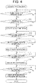
- FIG. 4 illustrates a flowchart of loading processing.
- FIG. 5 illustrates a flowchart of front test processing.
- FIG. 6 illustrates a flowchart of rear test processing.
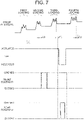
- FIG. 7 illustrates transition of the strut pressure, a state of the load dump brake 15, a state of the front wheel solenoid valve 27 (front solenoid), and a state of the rear wheel solenoid valve 31 (rear solenoid) during the loading processing.
- the loading processing is processing of, for example, loading earth and sand by a hydraulic excavator four times. While an operation of loading the earth and sand is performed by the hydraulic excavator, the controller 40 confirms whether the front wheel emergency brake system 13 and the rear wheel emergency brake system 14 can normally work. The controller 40 makes the loading processing start, for example, at the time when receiving the loading instruction through the communication I/F 44.
- the controller 40 determines whether the dump truck 1 is stopped based on the vehicle speed signals output from the vehicle speed sensors 55R, 55L (step S11). In addition, the controller 40 determines whether the vessel 5 is in the fallen position based on the detection signals output from the angle sensor 53 (step S12).
- step S11 Yes and step S12: Yes
- the controller 40 actuates the load dump brake 15 (step S13). That is, the controller 40 applies the control voltage to the load dump brake solenoid valve 34, whereby the rear wheels 4 are braked.
- the controller 40 delays execution of processes after step S15 until the first operation of loading earth and sand onto the vessel 5 is performed by the hydraulic excavator (step S14: No).
- the operation of loading earth and sand onto the vessel 5 is detected, for example, based on the detection signals output from the suspension sensors 51R, 51L, 52R, 52L.
- the controller 40 determines that the first loading operation is completed in the case where a state in which an amount of change in the strut pressure per unit time (for example, 1 second) is less than ⁇ P (for example, 200[kPa]) continues for a ⁇ T 1 period (for example, 10 seconds).
- step S14 the controller 40 delays processes after step S16 until the second operation of loading earth and sand onto the vessel 5 is performed by the hydraulic excavator (step S15: No). For example, as illustrated in FIG. 7 , the controller 40 determines that the second loading operation is completed when a ⁇ T 2 period has elapsed (for example, 5 seconds) after the amount of change in the strut pressure per unit time (for example, 1 second) exceeds ⁇ P.
- a ⁇ T 2 period has elapsed (for example, 5 seconds) after the amount of change in the strut pressure per unit time (for example, 1 second) exceeds ⁇ P.
- step S15 the controller 40 executes the front test processing illustrated in FIG. 5 (step S16).
- the front test processing is processing to be performed to test whether the front wheel emergency brake system 13 normally works by measuring the secondary pressure of the front wheel solenoid valve 27 associated with opening and closing operations of the front wheel solenoid valve 27.
- the controller 40 stops applying the control voltage to the front wheel solenoid valve 27 so as to open the front wheel solenoid valve 27 (step S31).
- the controller 40 delays subsequent processes until the secondary pressure of the front wheel solenoid valve 27 becomes equal to or more than a first threshold (for example, 18MPa), the controller 40 receives a traveling instruction through the communication I/F 44, or a threshold time has elapsed after the front wheel solenoid valve 27 is opened (step S32 to step S34).
- a first threshold for example, 18MPa
- step S32: Yes the controller 40 determines that the front wheel solenoid valve 27 is properly opened.
- the controller 40 applies the control voltage to the front wheel solenoid valve 27 so as to close the front wheel solenoid valve 27 (step S35).
- a second threshold for example, 1.5MPa
- step S32: No and step S33: Yes the controller 40 applies the control voltage to the front wheel solenoid valve 27 so as to close the front wheel solenoid valve 27(step S37).
- step S38: Yes the controller 40 causes the dump truck 1 to travel in accordance with the received traveling instruction (step S39) .
- step S33 corresponds to a case where an instruction for making the dump truck 1 travel is provided before the loading operations of a predetermined number of times (for example, four times) are performed. Accordingly, the controller 40 terminates the loading processing without executing the processes after step S17 illustrated in FIG. 4 .
- step S40 the controller 40 notifies the abnormality in the front wheel emergency brake system 13 (step S40).
- the abnormality may be notified, for example, to a management server through the communication I/F 44, or by displaying information on a display (not illustrated) installed in the cab 6.
- step S34 corresponds to a case where, even when the application of the control voltage to the front wheel solenoid valve 27 is stopped, the front wheel solenoid valve 27 cannot open the flow path (that is, the front wheel emergency brake system 13 does not work). Accordingly, the controller 40 terminates the loading processing without executing the processes after step S17 illustrated in FIG. 4 .
- step S17 the controller 40 delays the processes after step S18 until the third operation of loading earth and sand onto the vessel 5 is performed by the hydraulic excavator (step S17: No).
- the determination criterion of step S17 may be the same as that of step S15.
- step S17 the controller 40 executes the rear test processing illustrated in FIG. 6 (step S18).
- the rear test processing is processing to be performed to test whether the rear wheel emergency brake system 14 normally works by measuring the secondary pressure of the rear wheel solenoid valve 31 associated with opening and closing operations of the rear wheel solenoid valve 31. That is, the controller 40 executes the front test processing and the rear test processing alternately in step S16 and step S18.
- the controller 40 stops applying the control voltage to the front wheel solenoid valve 27 so as to brake the front wheels 3 (step S51).
- the controller 40 stops applying the control voltage to the load dump brake solenoid valve 34 so as to release the braking of the rear wheels 4 by the load dump brake 15 (step S52).
- the secondary pressure of the load dump brake solenoid valve 34 detected by the pressure sensor 36 is less than the second threshold, the releasing of the braking of the rear wheels 4 can be confirmed.
- the controller 40 executes, for the rear wheel emergency brake system 14, the same processes as those in steps S31 to S40 illustrated in FIG. 5 .
- the processes of steps S31 to S40 to be executed in the rear test processing are substantially the same as those described for the front test processing. Hereinafter, only the processes different from those of FIG. 5 will be described.
- the controller 40 stops applying the control voltage to the rear wheel solenoid valve 31 so as to open the rear wheel solenoid valve 31 in step S31. Furthermore, the controller 40 compares the secondary pressure of the rear wheel solenoid valve 31, which is based on the detection signal output from the pressure sensor 36, to the first threshold or the second threshold in steps S32, S36, and S38. Still further, the controller 40 applies the control voltage to the rear wheel solenoid valve 31 so as to close the rear wheel solenoid valve 31 in steps S35 and S37.
- step S36 the controller 40 applies the control voltage to the load dump brake solenoid valve 34 so as to actuate the load dump brake 15 (step S53).
- the secondary pressure of the load dump brake solenoid valve 34 detected by the pressure sensor 36 is the first threshold or more, it can be confirmed that the load dump brake 15 is actuated.
- the controller 40 applies the control voltage to the front wheel solenoid valve 27 so as to release the braking of the front wheels 3 by the front wheel emergency brake system 13 (step S54).
- the controller 40 terminates the rear test processing, and executes the processes after step S19 illustrated in FIG. 4 .
- step S19 the controller 40 determines whether the fourth operation of loading earth and sand on the vessel is completed by the hydraulic excavator 5 (step S19).
- the determination criterion of step S19 may be the same as that of step S15.
- step S19: Yes the controller 40 releases the load dump brake 15 and waits until receiving the traveling instruction (step S20).
- the front test processing (step S16) and the rear test processing (step S18) are executed. Since the operation of loading onto the vessel 5 is not performed in a state where both the front wheels 3 and the rear wheels 4 are braked, it is possible to prevent excessive impact from being imposed on the vehicle frame 2.
- the actuation test of the front wheel emergency brake system 13 is performed by opening and closing the front wheel solenoid valve 27 in a state where the load dump brake 15 is actuated. Furthermore, the actuation test of the rear wheel emergency brake system 14 is performed by opening and closing the rear wheel solenoid valve 31 in a state where the front wheel emergency brake system 13 actuated. Since the braking of the front wheels 3 and the rear wheels 4 is not released at the same time, overrunning of the dump truck 1 due to impact and inertial force during the loading can be prevented.
- the first loading operation by the hydraulic excavator may be started before the dump truck 1 is completely stopped.
- the dump truck 1 may move to the next destination immediately after the fourth loading operation by the hydraulic excavator is completed.
- the front test processing is executed in the interval between the second loading operation and the third loading operation while the rear test processing is executed in the interval of the third loading operation and the fourth loading operation.
- the front test processing and the rear test processing can be executed while the vehicle body frame 2 is in a stable state.
- step S33 upon receiving a traveling instruction during execution of the front test processing and the rear test processing (step S33: Yes), that is, while at -least either the front wheel solenoid valve 27 or the rear wheel solenoid valve 31 is opened, the controller 40 immediately closes at least either the front wheel solenoid valve 27 or the rear wheel solenoid valve 31 which has been opened (step S37), and terminates the loading processing.
- the controller 40 upon receiving a traveling instruction during execution of the front test processing and the rear test processing (step S33: Yes), that is, while at -least either the front wheel solenoid valve 27 or the rear wheel solenoid valve 31 is opened, the controller 40 immediately closes at least either the front wheel solenoid valve 27 or the rear wheel solenoid valve 31 which has been opened (step S37), and terminates the loading processing.
- step S34 in the case where the secondary pressure does reach the first threshold even when the application of the control voltage to the front wheel solenoid valve 27 and the rear wheel solenoid valve 31is stopped (step S34: Yes), the controller 40 notifies the abnormality in the front wheel emergency brake system 13 and the rear wheel emergency brake system 14 (step S40), and stops the loading processing.
- the controller 40 notifies the abnormality in the front wheel emergency brake system 13 and the rear wheel emergency brake system 14 (step S40), and stops the loading processing.
- steps S14, S15, S17, and S19 are one of the examples, and thus is not limited thereto.
- completion of the loading operations may be determined based on the strut pressure detected by a part of the four suspension sensors 51R, 51L, 52R, 52L, or based on an average value of the strut pressure detected by the four suspension sensors 51R, 51L, 52R, 52L. Using the average value enables appropriate determination of completion of the loading operations even in the case where earth and sand is loaded at a position deviated from the center of the vessel 5.
- the controller 40 may be configured to actuate the front wheel emergency brake system 13 and the rear wheel emergencybrake system 14 to assist the foot brake system 12 when detecting a risk of collision during a manual traveling mode.
Landscapes
- Engineering & Computer Science (AREA)
- Transportation (AREA)
- Mechanical Engineering (AREA)
- Regulating Braking Force (AREA)
- Braking Systems And Boosters (AREA)
- Valves And Accessory Devices For Braking Systems (AREA)
Abstract
Description
- The present invention relates to a dump truck equipped with an emergency brake system.
- An autonomous dump truck is equipped with an emergency brake system that brakes wheels in an emergency. The emergency brake system is configured to, for example, open a solenoid valve to supply a hydraulic brake device with hydraulic oil accumulated in an accumulator.
- Since the emergency brake system is used infrequently, there is a possibility that a spool of the solenoid valve gets stuck due to an influence of such as contamination. As a technique for solving such a technical problem, for example,
Patent Literature 1 discloses a dump truck in which a parking brake is actuated when a vehicle body is stopped so as to prevent sticking of the solenoid valve. - Patent Literature 1:
JP-B-5838255 - With this regard, however, when a timing of actuating the emergency brake system and a timing of loading such as earth and sand onto a. vessel overlap, the following problems may occur. The first problem is that, if a loading operation is performed in a state where both the front and rear emergency brake systems are actuated, excessive impact is imposed on a vehicle body. The second problem is that, when both the front and rear emergency brake systems are released at the same time, the vehicle body may overrun due to impact and inertial force during the loading operation.
- The present invention has been made in view of the circumstances above, and thus an object of the present invention is to provide a dump truck capable of performing an actuation test of an emergency brake system at an appropriate timing.
- In order to achieve the object above, the present invention provides a dump truck comprising: a vehicle body frame that rotatably supports front wheels and rear wheels through suspensions; a vessel that is supported on the vehicle body frame so as to be able to rise and fall between a rising position and a fallen position; a strut pressure sensor that is configured to detect pressure applied to the suspensions; a hydraulic pump that transfers hydraulic oil; a front wheel emergency brake system and a rear wheel emergency brake system that are configured to brake the front wheels and the rear wheels, respectively; and a controller that is configured to control operations of the front wheel emergency brake system and the rear wheel emergency brake system, wherein the front wheel emergency brake system and the rear wheel emergency brake system include, respectively: a front wheel accumulator and a rear wheel accumulator that are configured to accumulate the hydraulic oil supplied from the hydraulic pump; a front wheel brake device and a rear wheel brake device that are configured to be actuated by the hydraulic oil supplied from the front wheel accumulator and the rear wheel accumulator, respectively; and a front wheel solenoid valve and a rear wheel solenoid valve that are configured to open and close a flow path of the hydraulic oil extending from the front wheel accumulator to the front wheel brake device and a flow path of the hydraulic oil extending from the rear wheel accumulator to the rear wheel brake device, respectively, and the controller is configured to: determine whether the dump truck is stopped; determine whether the vessel is in the fallen position; determine whether a loading operation onto the vessel is completed based on the pressure detected by the strut pressure sensor; and in a case of determining that the dump truck is stopped, the vessel is in the fallen position, and the loading operation onto the vessel is completed, execute front test processing and rear test processing alternately, the front test processing being performed to test whether the front wheel emergency brake system normally works by measuring secondary pressure of the front wheel solenoid valve associated with opening and closing operations of the front wheel solenoid valve while the rear test processing being performed to test whether the rear wheel emergency brake system normally works by measuring secondary pressure of the rear wheel solenoid valve associated with opening and closing operations of the rear wheel solenoid valve.
- According to the present invention, it is possible to perform an actuation test of an emergency brake system at an appropriate timing. The problems, configurations, and advantageous effects other than those described above will be clarified by explanation of the embodiment below.
-
- [
FIG. 1] FIG. 1 is a side view of a dump truck according to the present embodiment. - [
FIG. 2] FIG. 2 illustrates a circuit of a hydraulic brake system equipped on the dump truck. - [
FIG. 3] FIG. 3 is a block diagram of a controller equipped on the dump truck. - [
FIG. 4] FIG. 4 illustrates a flowchart of loading processing. - [
FIG. 5] FIG. 5 illustrates a flowchart of front test processing. - [
FIG. 6] FIG. 6 illustrates a flowchart of rear test processing. - [
FIG. 7] FIG. 7 illustrates transition of strut pressure, a state of a load dump brake, a state of a front solenoid, and a state of a rear solenoid during loading processing. - An embodiment of a dump truck according to the present invention will be described with reference to the drawings.
FIG. 1 is a side view of adump truck 1 according to the present embodiment. In this specification, the front, rear, left, and right directions are referred based on a viewpoint of an operator who is in thedump truck 1 to operate thedump truck 1, unless otherwise noted. - As illustrated in
FIG. 1 , thedump truck 1 according to the present embodiment mainly includes avehicle body frame 2, a pair offront wheels 3 that is rotatably supported through a suspension 3S at both left and right ends of a front portion of thevehicle body frame 2, a pair ofrear wheels 4 that is rotatably supported through a suspension 4S at both left and right ends of a rear portion of thevehicle body frame 2, avessel 5 that is supported on thevehicle body frame 2 so as to be able to rise and fall, and acab 6 to be boarded by an operator who operates thedump truck 1. - Each of the pair of
front wheels 3 is a steering wheel whose steering angle changes in response to a steering operation. Each of the pair ofrear wheels 4 is a drive wheel that is rotated by drive force transmitted from travelingmotors FIG. 3 ). In this connection, thedump truck 1 includes a pair of travelingmotors rear wheels 4. - The
dump truck 1 includes suspension sensors (strut pressure sensors) 51R, 51L, 52R, 52L (seeFIG. 3 ) configured to detect pressure (hereinafter, referred to as "strut pressure") applied to the suspensions 3S, 4S for supporting the pair offront wheels 3 and the pair ofrear wheels 4, respectively, and output detection signals indicating detection results to a controller 40 (seeFIG. 3 ). Thesuspension sensor 51R detects the pressure applied to the suspension of the rightfront wheel 3, thesuspension sensor 51L detects the pressure applied to the suspension of theleft front wheel 3, thesuspension sensor 52R detects the pressure applied to the suspension of the rightrear wheel 4, and thesuspension sensor 52L detects the pressure applied to the suspension of the leftrear wheel 4. - The
traveling motors vehicle speed sensors FIG. 3 ). Each of thevehicle speed sensors dump truck 1, and output a vehicle speed signal indicating a detection result to thecontroller 40. More particularly, each of thevehicle speed sensors dump truck 1, rotational speed of thetraveling motors vehicle speed sensors - With a
hinge pin 8 on the rear portion of thevehicle frame 2 as the center, thevessel 5 rises and falls in the vertical direction by expansion and contraction of ahoist cylinder 7. Thehoist cylinder 7, whose one end is connected to thevehicle body frame 2 and the other end is connected to thevessel 5, is supplied with hydraulic oil from a hydraulic pump 11 (seeFIG. 2 ), thereby being expanded and contracted. More specifically, thevessel 5 is configured such that it can rise and fall between a fallen position illustrated by solid lines inFIG. 1 and a rising position illustrated by broken lines inFIG. 1 . - The fallen position is a position of the
vessel 5 at the time when thehoist cylinder 7 is contracted. In the fallen position, thevessel 5 can be loaded with earth and sand from such as a hydraulic excavator. The rising position is a position of thevessel 5 at the time when thehoist cylinder 7 is expanded. By rotating thevessel 5 from the fallen position to the rising position, the earth and sand loaded onto thevessel 5 is discharged. Thedump truck 1 includes anangle sensor 53 configured to detect an angle of thevessel 5 with respect to a reference position (for example, the fallen position), and output a detection signal indicating a detection result to the controller 40 (seeFIG. 3 ). - The
cab 6 is arranged on the left end of adeck 9 on the front end of thevehicle frame 2. Thecab 6 serves as an operator's cab to be boarded by the operator who operates thedump truck 1. Inside thecab 6, operation devices (accelerator pedal, brake pedal, hoist pedal, steering, lever, switch, etc.) used for operating thedump truck 1 are disposed. The operator in thecab 6 operates the operation devices, whereby thedump truck 1 travels (is accelerated or braked) and thevessel 5 rises. -
FIG. 2 illustrates a circuit of ahydraulic brake system 10 equipped on thedump truck 1. Thehydraulic brake system 10 is configured to brake the front andrear wheels hydraulic pump 11. Thehydraulic pump 11 is rotated by drive force transmitted from an engine (not illustrated), thereby transferring the hydraulic oil stored in ahydraulic oil tank 37. Thehydraulic brake system 10 mainly includes afoot brake system 12, a front wheelemergency brake system 13, a rear wheelemergency brake system 14, and a load dump brake (auxiliary brake) 15. - The
foot brake system 12 is configured to brake the front andrear wheels cab 6. Thefoot brake system 12 mainly includesaccumulators check valves - Each of the
accumulators hydraulic pump 11 through each of thecheck valves wheel brake device 21 is supplied with the hydraulic oil accumulated in theaccumulator 16 through ashuttle valve 20 while a rearwheel brake device 24 is supplied with the hydraulic oil accumulated in theaccumulator 17 throughshuttle valves - Each of the front
wheel brake device 21 and the rearwheel brake device 24 is supplied with the hydraulic oil, thereby braking thefront wheels 3 andrear wheels 4. The braking force from the frontwheel brake device 21 and the rearwheel brake device 24 increases as the stepping-on amount of the brake pedal increases. When the operator stops stepping on the brake pedal, the braking of the wheels performed by the frontwheel brake device 21 and the rearwheel brake device 24 is released. - The front wheel
emergency brake system 13 is configured to brake thefront wheels 3 in response to control by thecontroller 40. The front wheelemergency brake system 13 mainly includes afront wheel accumulator 25, acheck valve 26, a frontwheel solenoid valve 27, and apressure sensor 28. The front wheelemergency brake system 13 is a so-called "negative brake", which is configured to release the braking of thefront wheels 3 only while the control voltage is applied to the frontwheel solenoid valve 27 by thecontroller 40. - The
front wheel accumulator 25 accumulates the hydraulic oil supplied from thehydraulic pump 11 through thecheck valve 26. The frontwheel solenoid valve 27 is configured to open and close a flow path of the hydraulic oil extending from thefront wheel accumulator 25 to the frontwheel brake device 21 in response to control of thecontroller 40. Thepressure sensor 28 is configured to detect pressure of the hydraulic oil output from the front wheel accumulator 25 (primary pressure of the front wheel solenoid valve 27), and output a detection signal indicating a detection result to thecontroller 40. - When no control voltage is applied to the front
wheel solenoid valve 27 by thecontroller 40, the frontwheel solenoid valve 27 opens the flow path. Thus, the frontwheel brake device 21 is supplied with the hydraulic oil from thefront wheel accumulator 25 through theshuttle valve 20, whereby thefront wheels 3 are braked by the front wheelemergency brake system 13. On the other hand, when the control voltage is applied to the frontwheel solenoid valve 27 by thecontroller 40, the frontwheel solenoid valve 27 closes the flow path extending from thefront wheel accumulator 25 to the frontwheel brake device 21 so as to communicate the frontwheel brake device 21 to thehydraulic oil tank 37. Thus, the frontwheel brake device 21 is not supplied with the hydraulic oil from thefront wheel accumulator 25, and the hydraulic oil is refluxed from the frontwheel brake device 21 to thehydraulic oil tank 37. As a result, the braking of thefront wheels 3 that has been performed by the front wheelemergency brake system 13 is released. - The rear wheel
emergency brake system 14 is configured to brake the rear wheels4 in response to control by thecontroller 40. The rear wheelemergency brake system 14 mainly includes arear wheel accumulator 29, acheck valve 30, a rearwheel solenoid valve 31, and apressure sensor 32. The rear wheelemergency brake system 14 is a so-called "negative brake", which is configured to release the braking of therear wheels 4 only while the control voltage is applied to the rearwheel solenoid valve 31 by thecontroller 40. - The
rear wheel accumulator 29 accumulates the hydraulic oil supplied from thehydraulic pump 11 through thecheck valve 30. The rearwheel solenoid valve 31 is configured to open and close a flow path of the hydraulic oil extending from therear wheel accumulator 29 to the rearwheel brake device 24 in response to control of thecontroller 40. Thepressure sensor 32 is configured to detect pressure of the hydraulic oil output from the rear wheel accumulator 29 (primary pressure of the rear wheel solenoid valve 31), and output a detection signal indicating a detection result to thecontroller 40. - When no control voltage is applied to the rear
wheel solenoid valve 31 by thecontroller 40, the rearwheel solenoid valve 31 opens the flow path. Thus, the rearwheel brake device 24 is supplied with the hydraulic oil from therear wheel accumulator 29 through theshuttle valves rear wheels 4 are braked by the rear wheelemergency brake system 14. On the other hand, when the control voltage is applied to the rearwheel solenoid valve 31 by thecontroller 40, the rearwheel solenoid valve 31 closes the flow path extending from therear wheel accumulator 29 to the rearwheel brake device 24 so as to communicate the rearwheel brake device 24 to thehydraulic oil tank 37. Thus, the rearwheel brake device 24 is not supplied with the hydraulic oil from therear wheel accumulator 29, and the hydraulic oil is refluxed from the rearwheel brake device 24 to thehydraulic oil tank 37. As a result, the braking of therear wheels 4 that has been performed by the rear wheelemergency brake system 14 is released. - The load dump brake 15 is configured to lock the
rear wheels 4 in response to control by thecontroller 40. The operator operates the load dump brake 15 so as to prevent the vehicle from moving, for example, at the time of loading earth and sand onto thevessel 5 or discharging the earth and sand of thevessel 5. The load dump brake 15 mainly includes anaccumulator 33 and a load dumpbrake solenoid valve 34. Theaccumulator 33 accumulates the hydraulic oil supplied from thehydraulic pump 11. The load dumpbrake solenoid valve 34 is configured to open and close a flow path of the hydraulic oil extending from theaccumulator 33 to the rearwheel brake device 24 in response to the control by thecontroller 40. - When the control voltage is applied to the load dump
brake solenoid valve 34 by thecontroller 40, the load dumpbrake solenoid valve 34 opens the flow path. Thus, the rearwheel brake device 24 is supplied with the hydraulic oil from theaccumulator 33 through theshuttle valve 23, whereby therear wheels 4 are braked by the load dump brake 15. On the other hand, when no control voltage is applied to the load dumpbrake solenoid valve 34 by thecontroller 40, the load dumpbrake solenoid valve 34 closes the flow path extending from theaccumulator 33 to the rearwheel brake device 24 so as to communicate the rearwheel brake device 24 to thehydraulic oil tank 37. Thus, the rearwheel brake device 24 is not supplied with the hydraulic oil from theaccumulator 33, and the hydraulic oil is refluxed from the rearwheel brake device 24 to thehydraulic oil tank 37. As a result, the braking of therear wheels 4 that has been performed by the load dump brake 15 is released. - The front
wheel brake device 21 is commonly used in thefoot brake system 12 and the front wheelemergency brake system 13. The rearwheel brake device 24 is commonly used in thefoot brake system 12, the rear wheelemergency brake system 14, and the load dump brake 15. For example, the frontwheel brake device 21 is a disc type brake while the rearwheel brake device 24 is a wet type multiplate brake. - The
hydraulic brake system 10 further includes apressure sensor 35 configured to detect pressure of the hydraulic oil supplied to the frontwheel brake device 21, and output a detection signal indicating a detection result to thecontroller 40. Thepressure sensor 35 detects the secondary pressure of the frontwheel solenoid valve 27 while the front wheelemergency brake system 13 is in operation. - The
hydraulic brake system 10 further includes apressure sensor 36 configured to detect pressure of the hydraulic oil supplied to the rearwheel brake device 24, and output a detection signal indicating a detection result to thecontroller 40. Thepressure sensor 36 detects the secondary pressure of the rearwheel solenoid valve 31 while the rear wheelemergency brake system 14 is in operation. In addition, thepressure sensor 36 detects the secondary pressure of the load dumpbrake solenoid valve 34 while the load dump brake 15 is in operation. -
FIG. 3 is a block diagram of thecontroller 40 equipped on thedump truck 1. Thecontroller 40 is configured to control the hoistcylinder 7, the travelingmotors solenoid valves suspension sensors angle sensor 53, and thepressure sensors vehicle speed sensors controller 40 is configured to be communicable with external devices (for example, administration server and hydraulic excavator) through a communication I/F 44. - Each of the traveling
motors rear wheels 4, respectively. More particularly, the travelingmotors dump truck 1 travels (is accelerated). - An operation mode of the
controller 40 is switchable between a manual operation mode and an autonomous operation mode. The manual operation mode is used for operating thedump truck 1 in accordance with an operation by the operator in thecab 6. The autonomous operation mode is used for operating thedump truck 1 in accordance with an instruction received from an external device through the communication I/F 44. The manual operation mode and the autonomous operation mode are switched, for example, in accordance with an operation which is input by the operator to an operation device installed in thecab 6. - During the manual operation mode, the
controller 40 causes thedump truck 1 to be operated in accordance with the operation input by the operator with respect to the operation device while causing theaccumulators controller 40 causes thedump truck 1 to be operated in accordance with an instruction received through the communication I/F 44 while causing theaccumulators - The instruction received through the communication I/
F 44 may be, for example, a traveling instruction for causing thedump truck 1 to travel toward a destination, a loading instruction which actuates the load dump brake 15 when earth and sand is loaded onto thevessel 5 by such as a hydraulic excavator, and a discharging instruction for discharging the earth and sand loaded onto thevessel 5. - Upon receiving the traveling instruction, the
controller 40 causes thedump truck 1 to travel toward a destination, and causes thedump truck 1 to stop at the destination. At the time of braking thedump truck 1 at a scheduled timing, thecontroller 40 actuates the travelingmotors dump truck 1 in an unexpected event (for example, the case where thedump truck 1 deviates from a predetermined path by a predetermined distance, or the case where a risk of collision is detected), thecontroller 40 actuates the front wheelemergency brake system 13 and the rear wheelemergency brake system 14. - Upon receiving the loading instruction, the
controller 40 executes a brake test, which will be described later with reference toFIG. 4 . Upon receiving the discharging instruction, thecontroller 40 causes the hoistcylinder 7 to expand so that the earth and sand loaded onto thevessel 5 is discharged. - The
controller 40 includes a Central Processing Unit (CPU) 41, a Read Only Memory (ROM) 42, and a Random Access Memory (RAM) 43. In thecontroller 40, theCPU 41 reads a program code stored in theROM 42 and execute a program, thereby realizing processing which will be described later. TheRAM 43 is used as a work area at the time when theCPU 41 executes the program. - Meanwhile, a specific configuration of the
controller 40 is not limited thereto, and may be realized by hardware such as Application Specific Integrated Circuit (ASIC) or Field-Programmable Gate Array (FPGA). -
FIG. 4 illustrates a flowchart of loading processing.FIG. 5 illustrates a flowchart of front test processing.FIG. 6 illustrates a flowchart of rear test processing.FIG. 7 illustrates transition of the strut pressure, a state of the load dump brake 15, a state of the front wheel solenoid valve 27 (front solenoid), and a state of the rear wheel solenoid valve 31 (rear solenoid) during the loading processing. - The loading processing is processing of, for example, loading earth and sand by a hydraulic excavator four times. While an operation of loading the earth and sand is performed by the hydraulic excavator, the
controller 40 confirms whether the front wheelemergency brake system 13 and the rear wheelemergency brake system 14 can normally work. Thecontroller 40 makes the loading processing start, for example, at the time when receiving the loading instruction through the communication I/F 44. - Firstly, the
controller 40 determines whether thedump truck 1 is stopped based on the vehicle speed signals output from thevehicle speed sensors controller 40 determines whether thevessel 5 is in the fallen position based on the detection signals output from the angle sensor 53 (step S12). - Then, in the case of determining that the dump truck is stopped and the
vessel 5 is in the fallen position (step S11: Yes and step S12: Yes), thecontroller 40 actuates the load dump brake 15 (step S13). That is, thecontroller 40 applies the control voltage to the load dumpbrake solenoid valve 34, whereby therear wheels 4 are braked. - Next, the
controller 40 delays execution of processes after step S15 until the first operation of loading earth and sand onto thevessel 5 is performed by the hydraulic excavator (step S14: No). The operation of loading earth and sand onto thevessel 5 is detected, for example, based on the detection signals output from thesuspension sensors FIG. 7 , thecontroller 40 determines that the first loading operation is completed in the case where a state in which an amount of change in the strut pressure per unit time (for example, 1 second) is less than ΔP (for example, 200[kPa]) continues for a ΔT1 period (for example, 10 seconds). - In the case of determining that the first loading operation is completed (step S14: Yes), the
controller 40 delays processes after step S16 until the second operation of loading earth and sand onto thevessel 5 is performed by the hydraulic excavator (step S15: No). For example, as illustrated inFIG. 7 , thecontroller 40 determines that the second loading operation is completed when a ΔT2 period has elapsed (for example, 5 seconds) after the amount of change in the strut pressure per unit time (for example, 1 second) exceeds ΔP. - In the case of determining that the second loading operation is completed (step S15: Yes), the
controller 40 executes the front test processing illustrated inFIG. 5 (step S16). The front test processing is processing to be performed to test whether the front wheelemergency brake system 13 normally works by measuring the secondary pressure of the frontwheel solenoid valve 27 associated with opening and closing operations of the frontwheel solenoid valve 27. - Firstly, the
controller 40 stops applying the control voltage to the frontwheel solenoid valve 27 so as to open the front wheel solenoid valve 27 (step S31).Next, thecontroller 40 delays subsequent processes until the secondary pressure of the frontwheel solenoid valve 27 becomes equal to or more than a first threshold (for example, 18MPa), thecontroller 40 receives a traveling instruction through the communication I/F 44, or a threshold time has elapsed after the frontwheel solenoid valve 27 is opened (step S32 to step S34). - In the case of determining that the secondary pressure of the front
wheel solenoid valve 27 becomes equal to or more than the first threshold based on the detection signal output from the pressure sensor 35 (step S32: Yes), thecontroller 40 determines that the frontwheel solenoid valve 27 is properly opened. Next, thecontroller 40 applies the control voltage to the frontwheel solenoid valve 27 so as to close the front wheel solenoid valve 27 (step S35). In the case of determining that the secondary pressure of the frontwheel solenoid valve 27 becomes less than a second threshold (for example, 1.5MPa) based on the detection signal output from the pressure sensor 35 (step S36: Yes), thecontroller 40 terminates the front test processing. Then, thecontroller 40 executes the processes after step S17 illustrated inFIG. 4 . - In the case of receiving the traveling instruction before the secondary pressure of the front
wheel solenoid valve 27 becomes equal to or more than the first threshold (step S32: No and step S33: Yes), thecontroller 40 applies the control voltage to the frontwheel solenoid valve 27 so as to close the front wheel solenoid valve 27(step S37). Next, in the case of determining that the secondary pressure of the frontwheel solenoid valve 27 becomes less than the second threshold based on the detection signal output from the pressure sensor 35 (step S38: Yes), thecontroller 40 causes thedump truck 1 to travel in accordance with the received traveling instruction (step S39) . - Note that the case where the
controller 40 receives the traveling instruction in step S33 corresponds to a case where an instruction for making thedump truck 1 travel is provided before the loading operations of a predetermined number of times (for example, four times) are performed. Accordingly, thecontroller 40 terminates the loading processing without executing the processes after step S17 illustrated inFIG. 4 . - In the case where the threshold time has elapsed before the secondary pressure of the front
wheel solenoid valve 27 becomes equal to or more than the first threshold and before thecontroller 40 receives the traveling instruction (step S32: No, step S33: No, and step S34: Yes), thecontroller 40 notifies the abnormality in the front wheel emergency brake system 13 (step S40). The abnormality may be notified, for example, to a management server through the communication I/F 44, or by displaying information on a display (not illustrated) installed in thecab 6. - Note that the case where the threshold time has elapsed in step S34 corresponds to a case where, even when the application of the control voltage to the front
wheel solenoid valve 27 is stopped, the frontwheel solenoid valve 27 cannot open the flow path (that is, the front wheelemergency brake system 13 does not work). Accordingly, thecontroller 40 terminates the loading processing without executing the processes after step S17 illustrated inFIG. 4 . -
FIG. 4 is referred herein again. In the case where the front test processing is successfully completed, thecontroller 40 delays the processes after step S18 until the third operation of loading earth and sand onto thevessel 5 is performed by the hydraulic excavator (step S17: No). The determination criterion of step S17 may be the same as that of step S15. - In the case of determining that the third loading operation is completed (step S17: Yes), the
controller 40 executes the rear test processing illustrated inFIG. 6 (step S18). The rear test processing is processing to be performed to test whether the rear wheelemergency brake system 14 normally works by measuring the secondary pressure of the rearwheel solenoid valve 31 associated with opening and closing operations of the rearwheel solenoid valve 31. That is, thecontroller 40 executes the front test processing and the rear test processing alternately in step S16 and step S18. - Firstly, the
controller 40 stops applying the control voltage to the frontwheel solenoid valve 27 so as to brake the front wheels 3 (step S51). When the secondary pressure of the frontwheel solenoid valve 27 detected by thepressure sensor 35 is the first threshold or more, braking of thefront wheels 3 can be confirmed. Next, thecontroller 40 stops applying the control voltage to the load dumpbrake solenoid valve 34 so as to release the braking of therear wheels 4 by the load dump brake 15 (step S52). When the secondary pressure of the load dumpbrake solenoid valve 34 detected by thepressure sensor 36 is less than the second threshold, the releasing of the braking of therear wheels 4 can be confirmed. - Then, the
controller 40 executes, for the rear wheelemergency brake system 14, the same processes as those in steps S31 to S40 illustrated inFIG. 5 . The processes of steps S31 to S40 to be executed in the rear test processing are substantially the same as those described for the front test processing. Hereinafter, only the processes different from those ofFIG. 5 will be described. - Firstly, the
controller 40 stops applying the control voltage to the rearwheel solenoid valve 31 so as to open the rearwheel solenoid valve 31 in step S31. Furthermore, thecontroller 40 compares the secondary pressure of the rearwheel solenoid valve 31, which is based on the detection signal output from thepressure sensor 36, to the first threshold or the second threshold in steps S32, S36, and S38. Still further, thecontroller 40 applies the control voltage to the rearwheel solenoid valve 31 so as to close the rearwheel solenoid valve 31 in steps S35 and S37. - In the case where the processes of steps S31 to S40 in the rear test processing are normally completed (step S36: Yes), the
controller 40 applies the control voltage to the load dumpbrake solenoid valve 34 so as to actuate the load dump brake 15 (step S53). When the secondary pressure of the load dumpbrake solenoid valve 34 detected by thepressure sensor 36 is the first threshold or more, it can be confirmed that the load dump brake 15 is actuated. - Furthermore, the
controller 40 applies the control voltage to the frontwheel solenoid valve 27 so as to release the braking of thefront wheels 3 by the front wheel emergency brake system 13 (step S54). When the secondary pressure of the frontwheel solenoid valve 27 detected by thepressure sensor 35 is less than the second threshold, it can be confirmed that the braking of thefront wheels 3 is released. Then, thecontroller 40 terminates the rear test processing, and executes the processes after step S19 illustrated inFIG. 4 . -
FIG. 4 is referred herein again. In the case where the rear test processing is successfully completed, thecontroller 40 determines whether the fourth operation of loading earth and sand on the vessel is completed by the hydraulic excavator 5 (step S19). The determination criterion of step S19 may be the same as that of step S15. - In the case of determining that the fourth operation of loading onto the
vessel 5 is completed (step S19: Yes), thecontroller 40 releases the load dump brake 15 and waits until receiving the traveling instruction (step S20). - According to the embodiment above, for example, the following advantageous effects can be obtained.
- According to the embodiment above, in the intervals of the loading operations which are repeatedly performed by the hydraulic excavator, the front test processing (step S16) and the rear test processing (step S18) are executed. Since the operation of loading onto the
vessel 5 is not performed in a state where both thefront wheels 3 and therear wheels 4 are braked, it is possible to prevent excessive impact from being imposed on thevehicle frame 2. - Furthermore, according to the embodiment above, the actuation test of the front wheel
emergency brake system 13 is performed by opening and closing the frontwheel solenoid valve 27 in a state where the load dump brake 15 is actuated. Furthermore, the actuation test of the rear wheelemergency brake system 14 is performed by opening and closing the rearwheel solenoid valve 31 in a state where the front wheelemergency brake system 13 actuated. Since the braking of thefront wheels 3 and therear wheels 4 is not released at the same time, overrunning of thedump truck 1 due to impact and inertial force during the loading can be prevented. - The first loading operation by the hydraulic excavator may be started before the
dump truck 1 is completely stopped. In addition, thedump truck 1 may move to the next destination immediately after the fourth loading operation by the hydraulic excavator is completed. - With this regard, in the embodiment described above, among the four loading operations, the front test processing is executed in the interval between the second loading operation and the third loading operation while the rear test processing is executed in the interval of the third loading operation and the fourth loading operation. As a result, the front test processing and the rear test processing can be executed while the
vehicle body frame 2 is in a stable state. - Furthermore, in the embodiment above, upon receiving a traveling instruction during execution of the front test processing and the rear test processing (step S33: Yes), that is, while at -least either the front
wheel solenoid valve 27 or the rearwheel solenoid valve 31 is opened, thecontroller 40 immediately closes at least either the frontwheel solenoid valve 27 or the rearwheel solenoid valve 31 which has been opened (step S37), and terminates the loading processing. As a result, even in the case of receiving the traveling instruction before the loading operations of the specified number of times are completed, thedump truck 1 can smoothly start traveling. - Still further, in the embodiment above, in the case where the secondary pressure does reach the first threshold even when the application of the control voltage to the front
wheel solenoid valve 27 and the rear wheel solenoid valve 31is stopped (step S34: Yes), thecontroller 40 notifies the abnormality in the front wheelemergency brake system 13 and the rear wheel emergency brake system 14 (step S40), and stops the loading processing. As a result, it is possible to prevent thedump truck 1 from autonomously traveling in a state where the front wheelemergency brake system 13 and the rear wheelemergency brake system 14 do not work normally. - Note that the criterion used to determine completion of the loading operations in steps S14, S15, S17, and S19 is one of the examples, and thus is not limited thereto. In steps S14, S15, S17, and S19, completion of the loading operations may be determined based on the strut pressure detected by a part of the four
suspension sensors suspension sensors vessel 5. - In the embodiment above, an example in which the front wheel
emergency brake system 13 and the rear wheelemergency brake system 14 are actuated only during an autonomous traveling mode has been described, meanwhile, an actuation condition of the front wheelemergency brake system 13 and the rear wheelemergency brake system 14 is not limited thereto. For example, thecontroller 40 may be configured to actuate the front wheelemergency brake system 13 and the rearwheel emergencybrake system 14 to assist thefoot brake system 12 when detecting a risk of collision during a manual traveling mode. - It should be noted that the embodiment described above is an example which is provided to explain the present invention, and thus the present invention is not limited thereto. A person skilled in the art can make various modifications within the scope of the technical concept of the present invention.
-
- 1
- dump truck
- 2
- vehicle body frame
- 3
- front wheel
- 4
- rear wheel
- 5
- vessel
- 6
- cab
- 7
- hoist cylinder
- 8
- hinge pin
- 9
- deck
- 10
- hydraulic brake system
- 11
- hydraulic pump
- 12
- foot brake system
- 13
- front wheel emergency brake system
- 14
- rear wheel emergency brake system
- 15
- load dump brake (auxiliary brake)
- 16, 17, 33
- accumulator
- 25
- front wheelaccumulator
- 29
- rear wheel accumulator
- 18, 19, 26, 30
- check valve
- 20, 22, 23
- shuttle valve
- 21
- front wheel brake device
- 24
- rear wheel brake device
- 27
- front wheel solenoid valve
- 31
- rear wheel solenoid valve
- 34
- load dump brake solenoid valve
- 28, 32, 35, 36
- pressure sensor
- 37
- hydraulic oil tank
- 40
- controller
- 41
- CPU
- 42
- ROM
- 43
- RAM
- 44
- communication I/F
- 51R, 51L, 52R, 52L
- suspension sensor (strut pressure sensor)
- 53
- angle sensor
- 54R, 54L
- traveling motor
- 55R, 55L
- vehicle speed sensor
Claims (5)
- A dump truck comprising:a vehicle body frame that rotatably supports front wheels and rear wheels through suspensions;a vessel that is supported on the vehicle body frame so as to be able to rise and fall between a rising position and a fallen position;a strut pressure sensor that is configured to detect pressure applied to the suspensions;a hydraulic pump that transfers hydraulic oil;a front wheel emergency brake system and a rear wheel emergency brake system that are configured to brake the front wheels and the rear wheels, respectively; anda controller that is configured to control operations of the front wheel emergency brake system and the rear wheel emergency brake system, whereinthe front wheel emergency brake system and the rear wheel emergency brake system include, respectively: a front wheel accumulator and a rear wheel accumulator that are configured to accumulate the hydraulic oil supplied from the hydraulic pump;a front wheel brake device and a rear wheel brake device that are configured to be actuated by the hydraulic oil supplied from the front wheel accumulator and the rear wheel accumulator, respectively; anda front wheel solenoid valve and a rear wheel solenoid valve that are configured to open and close a flow path of the hydraulic oil extending from the front wheel accumulator to the front wheel brake device and a flow path of the hydraulic oil extending from the rear wheel accumulator to the rear wheel brake device, respectively, andthe controller is configured to:determine whether the dump truck is stopped;determine whether the vessel is in the fallen position;determine whether a loading operation onto the vessel is completed based on the pressure detected by the strut pressure sensor; andin a case of determining that the dump truck is stopped, the vessel is in the fallen position, and the loading operation onto the vessel is completed, execute front test processing and rear test processing alternately, the front test processing being performed to test whether the front wheel emergency brake system normally works by measuring secondary pressure of the front wheel solenoid valve associated with opening and closing operations of the front wheel solenoid valve while the rear test processing being performed to test whether the rear wheel emergency brake system normally works by measuring secondary pressure of the rear wheel solenoid valve associated with opening and closing operations of the rear wheel solenoid valve.
- The dump truck according to claim 1, further comprising an auxiliary brake that brakes the rear wheels by using the hydraulic oil supplied from the hydraulic pump, wherein
the controller is configured to, in a case of determining that the dump truck is stopped, the vessel is in the fallen position, and the loading operation onto the vessel is completed:execute the front test processing in a state where the auxiliary brake is actuated; andexecute the rear test processing in a state where the auxiliary brake is released and the front wheel emergency brake system is actuated. - The dump truck according to claim 1, wherein
the controller is configured to determine that the loading operation onto the vessel is completed in a case where a predetermined time elapses after an average value of the pressure applied to the suspensions of each of a pair of the front wheels and a pair of the rear wheels becomes equal to or more than a threshold. - The dump truck according to claim 1, wherein
the controller is configured to execute the front test processing and the rear test processing alternately in a case of determining two or more times that the loading operation onto the vessel is completed after determining that the dump truck is stopped and the vessel is in the fallen position. - The dump truck according to claim 1, wherein
the controller is configured to close at least either the front wheel solenoid valve or the rear wheel solenoid valve which has been opened in a case of receiving an instruction for making the dump truck travel while at least either the front wheel solenoid valve or the rear wheel solenoid valve is opened.
Applications Claiming Priority (2)
| Application Number | Priority Date | Filing Date | Title |
|---|---|---|---|
| JP2019173442 | 2019-09-24 | ||
| PCT/JP2020/034911 WO2021060072A1 (en) | 2019-09-24 | 2020-09-15 | Dump truck |
Publications (2)
| Publication Number | Publication Date |
|---|---|
| EP4035937A1 true EP4035937A1 (en) | 2022-08-03 |
| EP4035937A4 EP4035937A4 (en) | 2023-09-27 |
Family
ID=75166969
Family Applications (1)
| Application Number | Title | Priority Date | Filing Date |
|---|---|---|---|
| EP20869786.2A Pending EP4035937A4 (en) | 2019-09-24 | 2020-09-15 | Dump truck |
Country Status (5)
| Country | Link |
|---|---|
| US (1) | US11760325B2 (en) |
| EP (1) | EP4035937A4 (en) |
| JP (1) | JP7085696B2 (en) |
| CN (1) | CN113677577B (en) |
| WO (1) | WO2021060072A1 (en) |
Family Cites Families (19)
| Publication number | Priority date | Publication date | Assignee | Title |
|---|---|---|---|---|
| JPS5838255B2 (en) | 1979-06-11 | 1983-08-22 | 株式会社日立製作所 | Bulge forming equipment |
| JPS60143066U (en) * | 1984-03-05 | 1985-09-21 | 株式会社小松製作所 | Hydraulic release type brake device |
| DE4343314A1 (en) * | 1993-12-18 | 1995-06-22 | Bosch Gmbh Robert | External brake system |
| JPH1024826A (en) * | 1996-07-08 | 1998-01-27 | Denso Corp | Brake control device |
| JP2000219129A (en) * | 1999-01-29 | 2000-08-08 | Aisin Seiki Co Ltd | Brake controller |
| JP2001260858A (en) * | 2000-03-15 | 2001-09-26 | Unisia Jecs Corp | Brake control device |
| JP2003341505A (en) * | 2002-05-27 | 2003-12-03 | Komatsu Ltd | Emergency braking device of vehicle |
| US7869927B2 (en) * | 2005-07-07 | 2011-01-11 | Komatsu Ltd. | Retarder control device for working vehicle |
| JP4752406B2 (en) * | 2005-09-08 | 2011-08-17 | 株式会社アドヴィックス | Pneumatic-hydraulic pressure conversion brake device |
| CN103144621B (en) * | 2009-01-08 | 2015-05-27 | 株式会社小松制作所 | Traction control apparatus |
| JP5156693B2 (en) * | 2009-06-17 | 2013-03-06 | 日立建機株式会社 | Industrial vehicle engine speed control device |
| DE112012005887T5 (en) * | 2012-02-16 | 2014-11-13 | Hitachi Construction Machinery Co., Ltd. | Parking brake control device for transport vehicle |
| CN102717788A (en) * | 2012-06-01 | 2012-10-10 | 内蒙古北方重型汽车股份有限公司 | Braking device of heavy-duty mining dump truck |
| US9902397B2 (en) * | 2014-07-30 | 2018-02-27 | Komatsu Ltd. | Transporter vehicle and transporter vehicle control method |
| WO2016017014A1 (en) * | 2014-07-31 | 2016-02-04 | 株式会社小松製作所 | Work vehicle and control method of work vehicle |
| JP6267090B2 (en) * | 2014-09-29 | 2018-01-24 | 日立建機株式会社 | Transport stop control device for transport vehicle and transport vehicle equipped with the same |
| CN104401306B (en) * | 2014-12-02 | 2017-06-20 | 湘电重型装备有限公司 | A kind of Large Electric wheel quarry tipper hydraulic braking controls integrated system |
| JP6235507B2 (en) * | 2015-03-12 | 2017-11-22 | 日立建機株式会社 | Unloading work judgment device for transport vehicles |
| JP6781117B2 (en) * | 2017-07-28 | 2020-11-04 | 日立建機株式会社 | Dump truck braking system |
-
2020
- 2020-09-15 CN CN202080017298.0A patent/CN113677577B/en active Active
- 2020-09-15 WO PCT/JP2020/034911 patent/WO2021060072A1/en unknown
- 2020-09-15 JP JP2021548833A patent/JP7085696B2/en active Active
- 2020-09-15 EP EP20869786.2A patent/EP4035937A4/en active Pending
- 2020-09-15 US US17/434,788 patent/US11760325B2/en active Active
Also Published As
| Publication number | Publication date |
|---|---|
| EP4035937A4 (en) | 2023-09-27 |
| JPWO2021060072A1 (en) | 2021-12-09 |
| JP7085696B2 (en) | 2022-06-16 |
| US11760325B2 (en) | 2023-09-19 |
| CN113677577B (en) | 2023-07-25 |
| US20220185253A1 (en) | 2022-06-16 |
| WO2021060072A1 (en) | 2021-04-01 |
| CN113677577A (en) | 2021-11-19 |
Similar Documents
| Publication | Publication Date | Title |
|---|---|---|
| US4768636A (en) | Forward/reverse drive controller for controlling a rapid forward/reverse shifting of the driving mode of a vehicle equipped with an automatic transmission | |
| US6702405B1 (en) | Electric parking brake | |
| JP5087358B2 (en) | Pedal lock control device for work vehicle | |
| JPH11235969A (en) | Control method and device of vehicle brake device | |
| EP3575162B1 (en) | Brake system | |
| CN106627530A (en) | Automatic control method and system for assistant parking | |
| CN106965673A (en) | Shutoff control unit | |
| CN109398341A (en) | For running the method with the braking system of parking brake of automation | |
| JP4429076B2 (en) | Braking force control device | |
| EP4035937A1 (en) | Dump truck | |
| CN101574981B (en) | Vehicle having dual interrupt-type safety pedal and operation method thereof | |
| US20180231118A1 (en) | Work machine | |
| JP2006335314A (en) | Braking control device | |
| JP5087359B2 (en) | Pedal lock control device for work vehicle | |
| JP4524819B2 (en) | Industrial vehicle creep travel control device | |
| KR20200111816A (en) | Working machine | |
| JP2605951Y2 (en) | Vehicle braking device | |
| SE539410C2 (en) | System and method for improved vehicle stability by controlling a pneumatic park brake circuit arrangement | |
| JPH0585380B2 (en) | ||
| EP4163445A1 (en) | Work machine | |
| JP6987699B2 (en) | Vehicle control device | |
| CN115107712A (en) | Method for controlling a heavy vehicle on a slope | |
| KR20230042504A (en) | Method and system for automatic parking of vehicles | |
| CN112590739A (en) | Control system for a brake system and autonomous braking method for a vehicle | |
| KR20220106806A (en) | Redundant Brake System Control |
Legal Events
| Date | Code | Title | Description |
|---|---|---|---|
| STAA | Information on the status of an ep patent application or granted ep patent |
Free format text: STATUS: THE INTERNATIONAL PUBLICATION HAS BEEN MADE |
|
| PUAI | Public reference made under article 153(3) epc to a published international application that has entered the european phase |
Free format text: ORIGINAL CODE: 0009012 |
|
| STAA | Information on the status of an ep patent application or granted ep patent |
Free format text: STATUS: REQUEST FOR EXAMINATION WAS MADE |
|
| 17P | Request for examination filed |
Effective date: 20220329 |
|
| AK | Designated contracting states |
Kind code of ref document: A1 Designated state(s): AL AT BE BG CH CY CZ DE DK EE ES FI FR GB GR HR HU IE IS IT LI LT LU LV MC MK MT NL NO PL PT RO RS SE SI SK SM TR |
|
| DAV | Request for validation of the european patent (deleted) | ||
| DAX | Request for extension of the european patent (deleted) | ||
| A4 | Supplementary search report drawn up and despatched |
Effective date: 20230824 |
|
| RIC1 | Information provided on ipc code assigned before grant |
Ipc: B60T 13/14 20060101ALI20230818BHEP Ipc: B60T 17/22 20060101ALI20230818BHEP Ipc: B60P 1/04 20060101AFI20230818BHEP |