EP4035753B1 - Magnetic filter for processing a fluid - Google Patents
Magnetic filter for processing a fluid Download PDFInfo
- Publication number
- EP4035753B1 EP4035753B1 EP22154828.2A EP22154828A EP4035753B1 EP 4035753 B1 EP4035753 B1 EP 4035753B1 EP 22154828 A EP22154828 A EP 22154828A EP 4035753 B1 EP4035753 B1 EP 4035753B1
- Authority
- EP
- European Patent Office
- Prior art keywords
- filter
- magnets
- inserts
- magnetic
- housed
- Prior art date
- Legal status (The legal status is an assumption and is not a legal conclusion. Google has not performed a legal analysis and makes no representation as to the accuracy of the status listed.)
- Active
Links
Images
Classifications
-
- B—PERFORMING OPERATIONS; TRANSPORTING
- B01—PHYSICAL OR CHEMICAL PROCESSES OR APPARATUS IN GENERAL
- B01D—SEPARATION
- B01D29/00—Filters with filtering elements stationary during filtration, e.g. pressure or suction filters, not covered by groups B01D24/00 - B01D27/00; Filtering elements therefor
- B01D29/11—Filters with filtering elements stationary during filtration, e.g. pressure or suction filters, not covered by groups B01D24/00 - B01D27/00; Filtering elements therefor with bag, cage, hose, tube, sleeve or like filtering elements
- B01D29/31—Self-supporting filtering elements
- B01D29/35—Self-supporting filtering elements arranged for outward flow filtration
-
- B—PERFORMING OPERATIONS; TRANSPORTING
- B01—PHYSICAL OR CHEMICAL PROCESSES OR APPARATUS IN GENERAL
- B01D—SEPARATION
- B01D35/00—Filtering devices having features not specifically covered by groups B01D24/00 - B01D33/00, or for applications not specifically covered by groups B01D24/00 - B01D33/00; Auxiliary devices for filtration; Filter housing constructions
- B01D35/06—Filters making use of electricity or magnetism
-
- B—PERFORMING OPERATIONS; TRANSPORTING
- B01—PHYSICAL OR CHEMICAL PROCESSES OR APPARATUS IN GENERAL
- B01D—SEPARATION
- B01D35/00—Filtering devices having features not specifically covered by groups B01D24/00 - B01D33/00, or for applications not specifically covered by groups B01D24/00 - B01D33/00; Auxiliary devices for filtration; Filter housing constructions
- B01D35/16—Cleaning-out devices, e.g. for removing the cake from the filter casing or for evacuating the last remnants of liquid
-
- B—PERFORMING OPERATIONS; TRANSPORTING
- B03—SEPARATION OF SOLID MATERIALS USING LIQUIDS OR USING PNEUMATIC TABLES OR JIGS; MAGNETIC OR ELECTROSTATIC SEPARATION OF SOLID MATERIALS FROM SOLID MATERIALS OR FLUIDS; SEPARATION BY HIGH-VOLTAGE ELECTRIC FIELDS
- B03C—MAGNETIC OR ELECTROSTATIC SEPARATION OF SOLID MATERIALS FROM SOLID MATERIALS OR FLUIDS; SEPARATION BY HIGH-VOLTAGE ELECTRIC FIELDS
- B03C1/00—Magnetic separation
- B03C1/02—Magnetic separation acting directly on the substance being separated
- B03C1/28—Magnetic plugs and dipsticks
- B03C1/284—Magnetic plugs and dipsticks with associated cleaning means, e.g. retractable non-magnetic sleeve
-
- B—PERFORMING OPERATIONS; TRANSPORTING
- B03—SEPARATION OF SOLID MATERIALS USING LIQUIDS OR USING PNEUMATIC TABLES OR JIGS; MAGNETIC OR ELECTROSTATIC SEPARATION OF SOLID MATERIALS FROM SOLID MATERIALS OR FLUIDS; SEPARATION BY HIGH-VOLTAGE ELECTRIC FIELDS
- B03C—MAGNETIC OR ELECTROSTATIC SEPARATION OF SOLID MATERIALS FROM SOLID MATERIALS OR FLUIDS; SEPARATION BY HIGH-VOLTAGE ELECTRIC FIELDS
- B03C1/00—Magnetic separation
- B03C1/02—Magnetic separation acting directly on the substance being separated
- B03C1/28—Magnetic plugs and dipsticks
- B03C1/288—Magnetic plugs and dipsticks disposed at the outer circumference of a recipient
-
- C—CHEMISTRY; METALLURGY
- C02—TREATMENT OF WATER, WASTE WATER, SEWAGE, OR SLUDGE
- C02F—TREATMENT OF WATER, WASTE WATER, SEWAGE, OR SLUDGE
- C02F1/00—Treatment of water, waste water, or sewage
- C02F1/48—Treatment of water, waste water, or sewage with magnetic or electric fields
- C02F1/481—Treatment of water, waste water, or sewage with magnetic or electric fields using permanent magnets
- C02F1/482—Treatment of water, waste water, or sewage with magnetic or electric fields using permanent magnets located on the outer wall of the treatment device, i.e. not in contact with the liquid to be treated, e.g. detachable
-
- B—PERFORMING OPERATIONS; TRANSPORTING
- B03—SEPARATION OF SOLID MATERIALS USING LIQUIDS OR USING PNEUMATIC TABLES OR JIGS; MAGNETIC OR ELECTROSTATIC SEPARATION OF SOLID MATERIALS FROM SOLID MATERIALS OR FLUIDS; SEPARATION BY HIGH-VOLTAGE ELECTRIC FIELDS
- B03C—MAGNETIC OR ELECTROSTATIC SEPARATION OF SOLID MATERIALS FROM SOLID MATERIALS OR FLUIDS; SEPARATION BY HIGH-VOLTAGE ELECTRIC FIELDS
- B03C1/00—Magnetic separation
- B03C1/02—Magnetic separation acting directly on the substance being separated
- B03C1/025—High gradient magnetic separators
- B03C1/031—Component parts; Auxiliary operations
- B03C1/033—Component parts; Auxiliary operations characterised by the magnetic circuit
- B03C1/0332—Component parts; Auxiliary operations characterised by the magnetic circuit using permanent magnets
-
- B—PERFORMING OPERATIONS; TRANSPORTING
- B03—SEPARATION OF SOLID MATERIALS USING LIQUIDS OR USING PNEUMATIC TABLES OR JIGS; MAGNETIC OR ELECTROSTATIC SEPARATION OF SOLID MATERIALS FROM SOLID MATERIALS OR FLUIDS; SEPARATION BY HIGH-VOLTAGE ELECTRIC FIELDS
- B03C—MAGNETIC OR ELECTROSTATIC SEPARATION OF SOLID MATERIALS FROM SOLID MATERIALS OR FLUIDS; SEPARATION BY HIGH-VOLTAGE ELECTRIC FIELDS
- B03C2201/00—Details of magnetic or electrostatic separation
- B03C2201/18—Magnetic separation whereby the particles are suspended in a liquid
-
- B—PERFORMING OPERATIONS; TRANSPORTING
- B03—SEPARATION OF SOLID MATERIALS USING LIQUIDS OR USING PNEUMATIC TABLES OR JIGS; MAGNETIC OR ELECTROSTATIC SEPARATION OF SOLID MATERIALS FROM SOLID MATERIALS OR FLUIDS; SEPARATION BY HIGH-VOLTAGE ELECTRIC FIELDS
- B03C—MAGNETIC OR ELECTROSTATIC SEPARATION OF SOLID MATERIALS FROM SOLID MATERIALS OR FLUIDS; SEPARATION BY HIGH-VOLTAGE ELECTRIC FIELDS
- B03C2201/00—Details of magnetic or electrostatic separation
- B03C2201/22—Details of magnetic or electrostatic separation characterised by the magnetic field, e.g. its shape or generation
-
- C—CHEMISTRY; METALLURGY
- C02—TREATMENT OF WATER, WASTE WATER, SEWAGE, OR SLUDGE
- C02F—TREATMENT OF WATER, WASTE WATER, SEWAGE, OR SLUDGE
- C02F2303/00—Specific treatment goals
- C02F2303/22—Eliminating or preventing deposits, scale removal, scale prevention
Definitions
- the invention relates to a magnetic filter for processing a fluid.
- the invention has advantageous, though non-exclusive application in the processing of a fluid circulating in a thermal system, in particular in a heating and/or cooling system, to which explicit reference will be made in the description below without because of this losing in generality.
- magnetic filters are known, in which the fluid, besides undergoing a direct filtration through a filtering material, is caused to flow in contact with a magnet designed to hold back ferrous impurities.
- An example of these known filters is disclosed in WO2020128954 A1 , which shows a magnetic filter comprising two bodies connected to one another in a sealed manner and defining an inner chamber housing a cylindrical filtering cartridge with a metal mesh.
- the cartridge divides the chamber into an inner volume housing a magnetic element coaxial to the cartridge and an annular outer volume surrounding the cartridge.
- the upper body comprises an inlet port and an outlet port, which can be connected to the system, and houses a rotary shut-off element, which can rotate between a closing position, in which the ports are closed, and an opening position, in which the inlet port communicates with the inner volume and the outlet port communicates with the outer volume of the chamber. Therefore, the inflow brushes the magnetic element, which holds back ferromagnetic particles, flows through the filtering cartridge, which holds back impurities, and flows towards the outlet fitting.
- a scope of the present invention is to provide existing filters with an accessory magnetic filter element.
- the invention provides a filter according to claim 1.
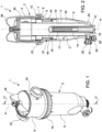
- number 1 indicates, as a whole, a magnetic sludge remover filter for a thermal system comprising a substantially cylindrical housing 2 with axis A defining internally a filtration chamber 3, and a filter cartridge 4 housed in the chamber 3.
- the housing 2 consists of an upper body 5 and a lower body 6, which are substantially cup-shaped and are telescopically coupled to one another, in a sealed manner, at the respective open ends 7, 8.
- the end 8 of the lower body 6 has an annular flange 9, which is axially locked against the end 7 of the upper body 5 by a ring nut 10 screwed onto the end 7.
- the lower body 6 integrally defines a hollow axial appendage 14 with axis A, which axially projects from a lower end 15 of the lower body 6 into the chamber 3.
- the appendage 14 is open at the bottom and closed at an upper end 16 thereof.
- a magnet 17 which is housed inside a screw 18, which is removably screwed into the appendage.
- the magnet 17 is polarized with its poles arranged on opposite sides of a vertical diametral plane ( figure 6 ).
- the cartridge 4 with a cylindrical shape with axis A, is conveniently made of metal mesh and divides the chamber 3 into an inner volume 19 and an outer volume 20coaxial to one another.
- the inner volume 19 opens downwards into an annular chamber 25 provided at the lower end 15 of the lower body 6 around the appendage 14.
- the filter 1 is further provided with a discharge valve 26 housed in a discharge duct 27 radially extending from the lower end 15 of the lower body 6 and communicating with the annular chamber 25.
- the discharge valve 26, operable by means of a wrench not shown herein, can rotate between a closing position and an opening position, in which the purge opening 28 is connected with the annular chamber 25.
- the upper body 5 ( figure 1 ) is provided with an inlet port 33 and an outlet port 34 coaxial to and diametrically opposite one another.
- the upper body 5 ( figure 2 ) houses a rotary shut-off valve 35, which is manually controlled by means of an upper knob 36.
- the shut-off valve 35 which is disclosed in the aforesaid international patent application WO2020128954 A1 and is not described in detail herein for it is not part of the invention, is movable between a first closing position, in which the ports 33, 34 are closed, and a second opening position, in which the inlet port 33 communicates with the inner volume 19 and the outlet port 34 communicates with the outer volume 20 of the chamber 3.
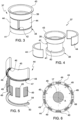
- the filter 1 comprises a magnetic accessory 37, which is mounted inside the body 2 coaxially thereto and is shown in figures 3 to 5 .
- the magnetic accessory 37 comprises a support 38 consisting of a tubular sleeve provided with a first axial end portion 39, a central portion 40 and a second axial end portion 41.
- the central portion 40 has a smaller diameter than the end portions 39, 41 so as to define an annular recess 42.
- the first end portion 39 has an outer circumferential end flange 43.
- the magnetic accessory 37 further comprises a pair of substantially half-cylindrical inserts 44 housed in the annular recess 42 so as to substantially form, as a whole, a cylindrical crown, whose outer surface is flush with the outer surface of the end portions 39, 41.
- Each insert 44 ( figure 5 ) comprises a body 45, which is conveniently made of a plastic material and is provided with a plurality of axial pockets 46 angularly equally spaced apart from one another, which axially lead to a curved recess 47 obtained in a base surface 48 of the insert.
- the insert 44 further comprises a plurality of magnets 49 having the shape of plates extending in an axial direction, which are housed in the respective pockets 46 having a corresponding shape.
- the insert 44 finally comprises a curved cap 50, which has a front projection 54 designed to engage the recess 47 in the base surface 48 of the body 45.
- the body 50 is fixed on the base surface 48, for example by means of ultrasound welding.
- the magnets 49 are conveniently magnetized so that the respective poles are on the main faces thereof.
- the positive pole of the magnets 49 is on the face facing outward in radial direction, whereas, in the other insert 44, the positive pole is on the inward facing face, so that the insert 44 with the positive poles of the magnets 49 on the inside faces the negative pole of the magnet 17 and the insert 44 with the negative poles of the magnets 49 on the inside faces the positive pole of the magnet 17 ( figure 6 ).
- the magnetic inserts 44 are firmly held in the annular recess 42 thanks to a mutual magnetic attraction, thus forming, with the support 38, a monolithic structure that can easily be handled even in an automated manner.
- the magnetic accessory 37 is housed in the body 2 of the filter 1 with the flange 43 in axial contact with the upper end 8 of the lower body 6 and axially interposed between said end and the shut-off valve 35.
- the inlet port 33 communicates with the inner volume 19 and the outlet port 34 communicates with the outer volume 20.
- the inflowing fluid flows from the inlet port 33 to the inner volume 19 and from the latter to the outer volume 20 through the filter cartridge 4. Therefore, impurities are held back in the inner volume; ferromagnetic impurities are attracted by the magnet 17 and settle on the outer surface of the appendage 14, whereas other impurities tend to precipitate in the annular chamber 25 due to gravity.
- the flow exiting volume 20 at the outlet port 34 flows by the magnetic accessory 37, which is arranged immediately below the shut-off valve 35. Possible ferromagnetic impurities that are so small-sized to pass through the meshes of the cartridge 4 can be intercepted before the fluid flows out of the filter 1 and back to the system.
- the filter 1 is self-cleaning. For the removal of sludge building up on the bottom, it is sufficient to remove the cap 29 and temporarily open the discharge valve 28, so as to decompress the system. Then, the discharge valve 28 is closed again and the shut-off valve 35 is closed as well by rotating the knob 36. The screw 18 can now be unscrewed, thus removing the magnet 17, which causes ferromagnetic impurities to precipitate to the bottom of the filter.
- the purging operation is completed by opening the discharge valve 26 again; by so doing, the fluid present in the chamber 3 flows out of the purge opening 28, dragging the impurities accumulated on the bottom of the lower body 6.
- the lower body 6 In order to clean the magnetic accessory 37, the lower body 6 has to be removed by unscrewing the ring nut 10.
- the magnetic inserts 44 can easily be separated from the support 38 for cleaning purposes.
- the filter 1 can lack a primary magnetic filtration carried out by means of the magnet 17, in which case the magnetic filtration is exclusively carried out by the magnetic accessory 37.
- the magnetic accessory 37 can further be used as "retrofit" in existing filters, provided with primary magnetic filtration or lacking it.
Landscapes
- Chemical & Material Sciences (AREA)
- Chemical Kinetics & Catalysis (AREA)
- Engineering & Computer Science (AREA)
- Water Supply & Treatment (AREA)
- Life Sciences & Earth Sciences (AREA)
- Hydrology & Water Resources (AREA)
- Environmental & Geological Engineering (AREA)
- Organic Chemistry (AREA)
- Filtration Of Liquid (AREA)
- Water Treatment By Electricity Or Magnetism (AREA)
Priority Applications (2)
| Application Number | Priority Date | Filing Date | Title |
|---|---|---|---|
| SI202230075T SI4035753T1 (sl) | 2021-02-02 | 2022-02-02 | Magnetni filter za predelavo tekočine |
| HRP20241703TT HRP20241703T1 (hr) | 2021-02-02 | 2022-02-02 | Magnetni filter za preradu tekućine |
Applications Claiming Priority (1)
| Application Number | Priority Date | Filing Date | Title |
|---|---|---|---|
| IT202100002198 | 2021-02-02 |
Publications (2)
| Publication Number | Publication Date |
|---|---|
| EP4035753A1 EP4035753A1 (en) | 2022-08-03 |
| EP4035753B1 true EP4035753B1 (en) | 2024-10-23 |
Family
ID=75439340
Family Applications (1)
| Application Number | Title | Priority Date | Filing Date |
|---|---|---|---|
| EP22154828.2A Active EP4035753B1 (en) | 2021-02-02 | 2022-02-02 | Magnetic filter for processing a fluid |
Country Status (6)
| Country | Link |
|---|---|
| EP (1) | EP4035753B1 (pl) |
| ES (1) | ES3010532T3 (pl) |
| HR (1) | HRP20241703T1 (pl) |
| HU (1) | HUE068923T2 (pl) |
| PL (1) | PL4035753T3 (pl) |
| SI (1) | SI4035753T1 (pl) |
Families Citing this family (2)
| Publication number | Priority date | Publication date | Assignee | Title |
|---|---|---|---|---|
| DK181611B1 (en) * | 2022-10-28 | 2024-06-26 | Respired Ltd | Separation device comprising a magnetic separation unit and method for fluid separation |
| WO2024223447A1 (fr) * | 2023-04-25 | 2024-10-31 | John Cockerill Hydrogen Belgium | Vibreur sur le filtre de lye |
Family Cites Families (6)
| Publication number | Priority date | Publication date | Assignee | Title |
|---|---|---|---|---|
| US3598237A (en) * | 1969-09-05 | 1971-08-10 | Sperry Rand Corp | Filter |
| US4067810A (en) * | 1976-02-09 | 1978-01-10 | Ofco, Inc. | Fluid filter magnet assembly |
| JPH0685015U (ja) * | 1992-11-09 | 1994-12-06 | 明 ▲高▼橋 | オイル・フイルター |
| CA2617669A1 (en) * | 2005-07-31 | 2007-03-22 | Meyer Fitoussi | Magnetized filtering device |
| IT201800020302A1 (it) * | 2018-12-20 | 2020-06-20 | Rbm Ibox S R L | Filtro per il trattamento di un fluido in una tubatura di un impianto di riscaldamento e/o raffrescamento, in particolare di tipo domestico e/o industriale |
| IT201800020332A1 (it) | 2018-12-20 | 2020-06-20 | Rbm Ibox S R L | Filtro per il trattamento di un fluido in un impianto di riscaldamento e/o raffrescamento, in particolare di tipo domestico e/o industriale |
-
2022
- 2022-02-02 SI SI202230075T patent/SI4035753T1/sl unknown
- 2022-02-02 HU HUE22154828A patent/HUE068923T2/hu unknown
- 2022-02-02 ES ES22154828T patent/ES3010532T3/es active Active
- 2022-02-02 PL PL22154828.2T patent/PL4035753T3/pl unknown
- 2022-02-02 EP EP22154828.2A patent/EP4035753B1/en active Active
- 2022-02-02 HR HRP20241703TT patent/HRP20241703T1/hr unknown
Also Published As
| Publication number | Publication date |
|---|---|
| SI4035753T1 (sl) | 2025-02-28 |
| EP4035753A1 (en) | 2022-08-03 |
| HRP20241703T1 (hr) | 2025-02-28 |
| HUE068923T2 (hu) | 2025-02-28 |
| PL4035753T3 (pl) | 2025-03-17 |
| ES3010532T3 (en) | 2025-04-03 |
Similar Documents
| Publication | Publication Date | Title |
|---|---|---|
| EP4035753B1 (en) | Magnetic filter for processing a fluid | |
| CN107889473B (zh) | 具有排水和可拆卸外部磁性元件的磁性过滤器 | |
| WO2018207083A1 (en) | Magnetic sludge separator for heating plants | |
| US8864865B2 (en) | Air filter element, filter housing and filter arrangement | |
| JP3924167B2 (ja) | フィルタ・バルブ装置 | |
| CN104918676B (zh) | 液体过滤装置 | |
| CN111201402A (zh) | 中央供热系统的磁过滤器 | |
| AU6407096A (en) | Reusable fluid filter and adapter | |
| EP3069772A1 (en) | Filter assembly | |
| CN103328062B (zh) | 用于内燃机的机油的过滤器系统和过滤器系统的可换式过滤器 | |
| US6814243B2 (en) | Replaceable filter with locking mechanism | |
| US6238560B1 (en) | Collapsible filter element assembly | |
| TWI858736B (zh) | 直列型過濾器 | |
| US20200316632A1 (en) | Offset showerhead filter | |
| US3476251A (en) | Filter and housing structure | |
| US20190262749A1 (en) | Filter device for fluids | |
| US20210121807A1 (en) | Air Filter Element Having a Circumferentially Protruding Clean Air Seal, Filter Housing and Air Filter | |
| JP3049769U (ja) | ろ水器用水流切換弁 | |
| CN213745042U (zh) | 磁性过滤球阀 | |
| EP2952791B1 (en) | Manifold module and filter assembly | |
| US7294160B2 (en) | Air cleaner | |
| EP3641906A1 (en) | Serviceable oil filter assembly | |
| CN220495800U (zh) | 过滤器 | |
| US20250050254A1 (en) | Composite Structure for Liquid Filtration Device | |
| CN209065649U (zh) | 供热管网的在线除污装置 |
Legal Events
| Date | Code | Title | Description |
|---|---|---|---|
| REG | Reference to a national code |
Ref country code: HR Ref legal event code: TUEP Ref document number: P20241703T Country of ref document: HR |
|
| PUAI | Public reference made under article 153(3) epc to a published international application that has entered the european phase |
Free format text: ORIGINAL CODE: 0009012 |
|
| STAA | Information on the status of an ep patent application or granted ep patent |
Free format text: STATUS: THE APPLICATION HAS BEEN PUBLISHED |
|
| AK | Designated contracting states |
Kind code of ref document: A1 Designated state(s): AL AT BE BG CH CY CZ DE DK EE ES FI FR GB GR HR HU IE IS IT LI LT LU LV MC MK MT NL NO PL PT RO RS SE SI SK SM TR |
|
| STAA | Information on the status of an ep patent application or granted ep patent |
Free format text: STATUS: REQUEST FOR EXAMINATION WAS MADE |
|
| 17P | Request for examination filed |
Effective date: 20230203 |
|
| RBV | Designated contracting states (corrected) |
Designated state(s): AL AT BE BG CH CY CZ DE DK EE ES FI FR GB GR HR HU IE IS IT LI LT LU LV MC MK MT NL NO PL PT RO RS SE SI SK SM TR |
|
| STAA | Information on the status of an ep patent application or granted ep patent |
Free format text: STATUS: EXAMINATION IS IN PROGRESS |
|
| 17Q | First examination report despatched |
Effective date: 20230508 |
|
| RAP1 | Party data changed (applicant data changed or rights of an application transferred) |
Owner name: R.B.M. S.P.A. |
|
| GRAP | Despatch of communication of intention to grant a patent |
Free format text: ORIGINAL CODE: EPIDOSNIGR1 |
|
| STAA | Information on the status of an ep patent application or granted ep patent |
Free format text: STATUS: GRANT OF PATENT IS INTENDED |
|
| INTG | Intention to grant announced |
Effective date: 20240515 |
|
| P01 | Opt-out of the competence of the unified patent court (upc) registered |
Free format text: CASE NUMBER: APP_42851/2024 Effective date: 20240722 |
|
| GRAS | Grant fee paid |
Free format text: ORIGINAL CODE: EPIDOSNIGR3 |
|
| GRAA | (expected) grant |
Free format text: ORIGINAL CODE: 0009210 |
|
| STAA | Information on the status of an ep patent application or granted ep patent |
Free format text: STATUS: THE PATENT HAS BEEN GRANTED |
|
| AK | Designated contracting states |
Kind code of ref document: B1 Designated state(s): AL AT BE BG CH CY CZ DE DK EE ES FI FR GB GR HR HU IE IS IT LI LT LU LV MC MK MT NL NO PL PT RO RS SE SI SK SM TR |
|
| REG | Reference to a national code |
Ref country code: GB Ref legal event code: FG4D |
|
| REG | Reference to a national code |
Ref country code: CH Ref legal event code: EP |
|
| REG | Reference to a national code |
Ref country code: DE Ref legal event code: R096 Ref document number: 602022006935 Country of ref document: DE |
|
| REG | Reference to a national code |
Ref country code: IE Ref legal event code: FG4D |
|
| REG | Reference to a national code |
Ref country code: NL Ref legal event code: FP |
|
| REG | Reference to a national code |
Ref country code: HR Ref legal event code: ODRP Ref document number: P20241703T Country of ref document: HR Payment date: 20250121 Year of fee payment: 4 |
|
| REG | Reference to a national code |
Ref country code: LT Ref legal event code: MG9D |
|
| REG | Reference to a national code |
Ref country code: HR Ref legal event code: T1PR Ref document number: P20241703 Country of ref document: HR Ref country code: HU Ref legal event code: AG4A Ref document number: E068923 Country of ref document: HU |
|
| PGFP | Annual fee paid to national office [announced via postgrant information from national office to epo] |
Ref country code: NL Payment date: 20250224 Year of fee payment: 4 |
|
| PGFP | Annual fee paid to national office [announced via postgrant information from national office to epo] |
Ref country code: HU Payment date: 20250205 Year of fee payment: 4 |
|
| PG25 | Lapsed in a contracting state [announced via postgrant information from national office to epo] |
Ref country code: PT Free format text: LAPSE BECAUSE OF FAILURE TO SUBMIT A TRANSLATION OF THE DESCRIPTION OR TO PAY THE FEE WITHIN THE PRESCRIBED TIME-LIMIT Effective date: 20250224 Ref country code: IS Free format text: LAPSE BECAUSE OF FAILURE TO SUBMIT A TRANSLATION OF THE DESCRIPTION OR TO PAY THE FEE WITHIN THE PRESCRIBED TIME-LIMIT Effective date: 20250223 |
|
| PGFP | Annual fee paid to national office [announced via postgrant information from national office to epo] |
Ref country code: DE Payment date: 20250226 Year of fee payment: 4 Ref country code: HR Payment date: 20250121 Year of fee payment: 4 |
|
| PG25 | Lapsed in a contracting state [announced via postgrant information from national office to epo] |
Ref country code: FI Free format text: LAPSE BECAUSE OF FAILURE TO SUBMIT A TRANSLATION OF THE DESCRIPTION OR TO PAY THE FEE WITHIN THE PRESCRIBED TIME-LIMIT Effective date: 20241023 |
|
| PG25 | Lapsed in a contracting state [announced via postgrant information from national office to epo] |
Ref country code: BG Free format text: LAPSE BECAUSE OF FAILURE TO SUBMIT A TRANSLATION OF THE DESCRIPTION OR TO PAY THE FEE WITHIN THE PRESCRIBED TIME-LIMIT Effective date: 20241023 |
|
| PGFP | Annual fee paid to national office [announced via postgrant information from national office to epo] |
Ref country code: ES Payment date: 20250314 Year of fee payment: 4 |
|
| PG25 | Lapsed in a contracting state [announced via postgrant information from national office to epo] |
Ref country code: NO Free format text: LAPSE BECAUSE OF FAILURE TO SUBMIT A TRANSLATION OF THE DESCRIPTION OR TO PAY THE FEE WITHIN THE PRESCRIBED TIME-LIMIT Effective date: 20250123 |
|
| PG25 | Lapsed in a contracting state [announced via postgrant information from national office to epo] |
Ref country code: LV Free format text: LAPSE BECAUSE OF FAILURE TO SUBMIT A TRANSLATION OF THE DESCRIPTION OR TO PAY THE FEE WITHIN THE PRESCRIBED TIME-LIMIT Effective date: 20241023 Ref country code: GR Free format text: LAPSE BECAUSE OF FAILURE TO SUBMIT A TRANSLATION OF THE DESCRIPTION OR TO PAY THE FEE WITHIN THE PRESCRIBED TIME-LIMIT Effective date: 20250124 |
|
| PGFP | Annual fee paid to national office [announced via postgrant information from national office to epo] |
Ref country code: BE Payment date: 20250224 Year of fee payment: 4 Ref country code: AT Payment date: 20250417 Year of fee payment: 4 Ref country code: SI Payment date: 20250124 Year of fee payment: 4 |
|
| PGFP | Annual fee paid to national office [announced via postgrant information from national office to epo] |
Ref country code: FR Payment date: 20250224 Year of fee payment: 4 Ref country code: CZ Payment date: 20250116 Year of fee payment: 4 Ref country code: PL Payment date: 20250123 Year of fee payment: 4 |
|
| PGFP | Annual fee paid to national office [announced via postgrant information from national office to epo] |
Ref country code: IT Payment date: 20250228 Year of fee payment: 4 |
|
| PG25 | Lapsed in a contracting state [announced via postgrant information from national office to epo] |
Ref country code: RS Free format text: LAPSE BECAUSE OF FAILURE TO SUBMIT A TRANSLATION OF THE DESCRIPTION OR TO PAY THE FEE WITHIN THE PRESCRIBED TIME-LIMIT Effective date: 20250123 |
|
| PG25 | Lapsed in a contracting state [announced via postgrant information from national office to epo] |
Ref country code: SM Free format text: LAPSE BECAUSE OF FAILURE TO SUBMIT A TRANSLATION OF THE DESCRIPTION OR TO PAY THE FEE WITHIN THE PRESCRIBED TIME-LIMIT Effective date: 20241023 |
|
| PG25 | Lapsed in a contracting state [announced via postgrant information from national office to epo] |
Ref country code: DK Free format text: LAPSE BECAUSE OF FAILURE TO SUBMIT A TRANSLATION OF THE DESCRIPTION OR TO PAY THE FEE WITHIN THE PRESCRIBED TIME-LIMIT Effective date: 20241023 |
|
| PG25 | Lapsed in a contracting state [announced via postgrant information from national office to epo] |
Ref country code: EE Free format text: LAPSE BECAUSE OF FAILURE TO SUBMIT A TRANSLATION OF THE DESCRIPTION OR TO PAY THE FEE WITHIN THE PRESCRIBED TIME-LIMIT Effective date: 20241023 |
|
| PG25 | Lapsed in a contracting state [announced via postgrant information from national office to epo] |
Ref country code: RO Free format text: LAPSE BECAUSE OF FAILURE TO SUBMIT A TRANSLATION OF THE DESCRIPTION OR TO PAY THE FEE WITHIN THE PRESCRIBED TIME-LIMIT Effective date: 20241023 |
|
| REG | Reference to a national code |
Ref country code: DE Ref legal event code: R097 Ref document number: 602022006935 Country of ref document: DE |
|
| PG25 | Lapsed in a contracting state [announced via postgrant information from national office to epo] |
Ref country code: SK Free format text: LAPSE BECAUSE OF FAILURE TO SUBMIT A TRANSLATION OF THE DESCRIPTION OR TO PAY THE FEE WITHIN THE PRESCRIBED TIME-LIMIT Effective date: 20241023 |
|
| PLBE | No opposition filed within time limit |
Free format text: ORIGINAL CODE: 0009261 |
|
| STAA | Information on the status of an ep patent application or granted ep patent |
Free format text: STATUS: NO OPPOSITION FILED WITHIN TIME LIMIT |
|
| PG25 | Lapsed in a contracting state [announced via postgrant information from national office to epo] |
Ref country code: SE Free format text: LAPSE BECAUSE OF FAILURE TO SUBMIT A TRANSLATION OF THE DESCRIPTION OR TO PAY THE FEE WITHIN THE PRESCRIBED TIME-LIMIT Effective date: 20241023 |
|
| PG25 | Lapsed in a contracting state [announced via postgrant information from national office to epo] |
Ref country code: MC Free format text: LAPSE BECAUSE OF FAILURE TO SUBMIT A TRANSLATION OF THE DESCRIPTION OR TO PAY THE FEE WITHIN THE PRESCRIBED TIME-LIMIT Effective date: 20241023 |
|
| REG | Reference to a national code |
Ref country code: CH Ref legal event code: PL |
|
| 26N | No opposition filed |
Effective date: 20250724 |
|
| PG25 | Lapsed in a contracting state [announced via postgrant information from national office to epo] |
Ref country code: LU Free format text: LAPSE BECAUSE OF NON-PAYMENT OF DUE FEES Effective date: 20250202 |
|
| PG25 | Lapsed in a contracting state [announced via postgrant information from national office to epo] |
Ref country code: CH Free format text: LAPSE BECAUSE OF NON-PAYMENT OF DUE FEES Effective date: 20250228 |
|
| PG25 | Lapsed in a contracting state [announced via postgrant information from national office to epo] |
Ref country code: IE Free format text: LAPSE BECAUSE OF NON-PAYMENT OF DUE FEES Effective date: 20250202 |