EP4035608B1 - Medizinisches instrument - Google Patents
Medizinisches instrument Download PDFInfo
- Publication number
- EP4035608B1 EP4035608B1 EP20882016.7A EP20882016A EP4035608B1 EP 4035608 B1 EP4035608 B1 EP 4035608B1 EP 20882016 A EP20882016 A EP 20882016A EP 4035608 B1 EP4035608 B1 EP 4035608B1
- Authority
- EP
- European Patent Office
- Prior art keywords
- stent
- protrusions
- medical instrument
- distal end
- clamping
- Prior art date
- Legal status (The legal status is an assumption and is not a legal conclusion. Google has not performed a legal analysis and makes no representation as to the accuracy of the status listed.)
- Active
Links
Images


Classifications
-
- A—HUMAN NECESSITIES
- A61—MEDICAL OR VETERINARY SCIENCE; HYGIENE
- A61B—DIAGNOSIS; SURGERY; IDENTIFICATION
- A61B17/00—Surgical instruments, devices or methods
- A61B17/12—Surgical instruments, devices or methods for ligaturing or otherwise compressing tubular parts of the body, e.g. blood vessels or umbilical cord
- A61B17/12022—Occluding by internal devices, e.g. balloons or releasable wires
- A61B17/12099—Occluding by internal devices, e.g. balloons or releasable wires characterised by the location of the occluder
- A61B17/12122—Occluding by internal devices, e.g. balloons or releasable wires characterised by the location of the occluder within the heart
-
- A—HUMAN NECESSITIES
- A61—MEDICAL OR VETERINARY SCIENCE; HYGIENE
- A61B—DIAGNOSIS; SURGERY; IDENTIFICATION
- A61B17/00—Surgical instruments, devices or methods
- A61B17/12—Surgical instruments, devices or methods for ligaturing or otherwise compressing tubular parts of the body, e.g. blood vessels or umbilical cord
- A61B17/12022—Occluding by internal devices, e.g. balloons or releasable wires
- A61B17/12027—Type of occlusion
- A61B17/12031—Type of occlusion complete occlusion
-
- A—HUMAN NECESSITIES
- A61—MEDICAL OR VETERINARY SCIENCE; HYGIENE
- A61B—DIAGNOSIS; SURGERY; IDENTIFICATION
- A61B17/00—Surgical instruments, devices or methods
- A61B17/12—Surgical instruments, devices or methods for ligaturing or otherwise compressing tubular parts of the body, e.g. blood vessels or umbilical cord
- A61B17/12022—Occluding by internal devices, e.g. balloons or releasable wires
- A61B17/12131—Occluding by internal devices, e.g. balloons or releasable wires characterised by the type of occluding device
- A61B17/12168—Occluding by internal devices, e.g. balloons or releasable wires characterised by the type of occluding device having a mesh structure
- A61B17/12172—Occluding by internal devices, e.g. balloons or releasable wires characterised by the type of occluding device having a mesh structure having a pre-set deployed three-dimensional shape
-
- A—HUMAN NECESSITIES
- A61—MEDICAL OR VETERINARY SCIENCE; HYGIENE
- A61F—FILTERS IMPLANTABLE INTO BLOOD VESSELS; PROSTHESES; DEVICES PROVIDING PATENCY TO, OR PREVENTING COLLAPSING OF, TUBULAR STRUCTURES OF THE BODY, e.g. STENTS; ORTHOPAEDIC, NURSING OR CONTRACEPTIVE DEVICES; FOMENTATION; TREATMENT OR PROTECTION OF EYES OR EARS; BANDAGES, DRESSINGS OR ABSORBENT PADS; FIRST-AID KITS
- A61F2/00—Filters implantable into blood vessels; Prostheses, i.e. artificial substitutes or replacements for parts of the body; Appliances for connecting them with the body; Devices providing patency to, or preventing collapsing of, tubular structures of the body, e.g. stents
- A61F2/02—Prostheses implantable into the body
- A61F2/24—Heart valves ; Vascular valves, e.g. venous valves; Heart implants, e.g. passive devices for improving the function of the native valve or the heart muscle; Transmyocardial revascularisation [TMR] devices; Valves implantable in the body
-
- A—HUMAN NECESSITIES
- A61—MEDICAL OR VETERINARY SCIENCE; HYGIENE
- A61B—DIAGNOSIS; SURGERY; IDENTIFICATION
- A61B17/00—Surgical instruments, devices or methods
- A61B17/12—Surgical instruments, devices or methods for ligaturing or otherwise compressing tubular parts of the body, e.g. blood vessels or umbilical cord
- A61B17/12022—Occluding by internal devices, e.g. balloons or releasable wires
- A61B2017/1205—Introduction devices
- A61B2017/12054—Details concerning the detachment of the occluding device from the introduction device
Definitions
- the present invention relates to the technical field of medical instruments and, more specifically, to a medical instrument.
- Atrial fibrillation is the most common perpetual arrhythmia seen in clinical practice and is associated with a risk of causing ischemic stroke. Therefore, the prevention of atrial fibrillation is of great significance.
- LAA left atrial appendage
- Existing occluders used for LAA closure can be generally divided into two categories: cage-like ones represented by Watchman devices, which are characterized by an easy-to-fabricate integral skeleton; and two-piece ones represented by LAmbre devices, which are characterized by consisting of a locator and an occluding disc connected to the locator. During use, the locator is anchored in the LAA to provide a riveting effect. LAA closure relies principally on the occluding disc that fits over the LAA orifice, although the locator also makes a certain contribution to the occlusion. Both these types of occluders suffer from the drawback that, once they are decoupled and released, their retrieval is difficult and has to rely on the use of a snare which is, however, associated with a very low success rate.
- US 2016/0302950 A1 , US 2017/0266003 A1 , US 2011/0178588 A1 and US 2018/0110622 A1 disclose medical devices comprising a stent according to the preamble of claim 1.
- a present embodiment provides a medical instrument comprising a stent having a proximal end and an opposing distal end, wherein the distal end of the stent is configured with an expanded configuration and a collapsed configuration, wherein a trailing section of the stent at the distal end comprises a plurality of protrusions, and wherein the medical instrument further comprises a constraining structure comprising a body and a clamping mechanism, the clamping mechanism disposed at the distal end of the body, the body extending from the proximal end of the stent to the distal end thereof, the clamping mechanism limiting relative movement of the protrusions by passing through all or some of them.
- the clamping mechanism may comprise a single clamping member which passes either sequentially through all the protrusions or spaced ones of the protrusions.
- the clamping mechanism may comprise at least one clamping member each passing at opposite ends through different ones of the protrusion.
- the clamping mechanism may comprise a plurality of clamping members arranged circumferentially around the stent, each of the clamping members passing at one end thereof through one of the protrusions, the clamping members passing through different protrusions.
- the number of the clamping members may be smaller than or equal to the number of the protrusions.
- the number of the protrusions may be twice the number of the clamping members.
- each clamping member may be a wire-like member made of a elastic material.
- the material of the wire-like member may be a nickel-titanium alloy or stainless steel.
- the clamping member may be shaped like the letter “C” or "V".
- each clamping member may be curved relative to the body at an angle ranging from 30° to 180°.
- the medical instrument may further comprise a proximal fixation member disposed at the proximal end of the stent and configured to bring the stent into a closed configuration at the proximal end.
- a proximal fixation member disposed at the proximal end of the stent and configured to bring the stent into a closed configuration at the proximal end.
- the medical instrument may further comprise a distal fixation member and a pull mechanism, the pull mechanism comprising a number of pull elements each tied, at a first end, to the distal fixation member and, at a second end, to the distal end of the stent, the distal fixation member configured to be able to move toward the proximal fixation member and thus switch the distal end of the stent from the expanded configuration to the collapsed configuration.
- the pull mechanism comprising a number of pull elements each tied, at a first end, to the distal fixation member and, at a second end, to the distal end of the stent, the distal fixation member configured to be able to move toward the proximal fixation member and thus switch the distal end of the stent from the expanded configuration to the collapsed configuration.
- the medical instrument may further comprise a biocompatible membrane which covers part of a surface of the stent, with the protrusions exposed therefrom.
- the medical instrument may further comprise a delivery device comprising a hollow push tube and a drive component, the hollow push tube detachably coupled at a distal end thereof to the proximal end of the stent, the drive component inserted through the hollow push tube into the stent and detachably coupled within the stent to the distal end thereof, the drive component configured to cause the distal end to switch from the expanded configuration to the collapsed configuration, wherein the body extends from the proximal end of the stent through the hollow push tube to the distal end of the stent.
- a delivery device comprising a hollow push tube and a drive component, the hollow push tube detachably coupled at a distal end thereof to the proximal end of the stent, the drive component inserted through the hollow push tube into the stent and detachably coupled within the stent to the distal end thereof, the drive component configured to cause the distal end to switch from the expanded configuration to the collapsed configuration, wherein the body extends from the prox
- the medical instrument of the present invention according to claim 1 has the following advantages over the prior art:
- proximal end generally refers to an end closer to an operator who operates a medical instrument
- distal end generally refers to an end farther away from the operator.
- the core concept of the present invention is to provide a medical instrument including a stent and a constraining structure configured to constrain a trailing section of the stent to avoid both excessive deformation of the stent and tangling of its trailing section during its delivery. These can facilitate successful expansion of the stent after it is released from a sheath, thereby ensuring its successful release and resulting in an increased success rate of a surgical procedure using the stent. It is added that the medical instrument of the present invention can be used to close the LAA as well as other body lumens, such as blood vessels, or as a vascular filter, a heart valve stent, a stent graft, or the like.
- the stent of the present invention has a first proximal end and an opposing first distal end.
- the first distal end is configured with an expanded configuration and a collapsed configuration.
- the trailing section at the first distal end includes a number of protrusions.
- the constraining structure of the present invention includes a body and clamping mechanism provided at a distal end of the body. During practical use, the body extends from the first proximal end to the first distal end, and the clamping mechanism passes through all or some of the protrusions and thus limits their relative movement.
- the stent is allowed to be less deformed within a delivery sheath, additionally reducing the risk of tangling of the stent's trailing section.
- the medical instrument of the present invention may further include a proximal fixation member, which is disposed at the first proximal end and configured to bring the stent into a closed configuration at the same end.
- the medical instrument may further include a distal fixation member and a pull mechanism.
- the pull mechanism may include a number of pull elements (including, but are not limited to, those capable of withstanding only tension, such as strings and wires, or those capable of withstanding both compression and tension). In the pull mechanism, each of the pull elements may be tied, at a first end, to the distal fixation member and, at a second end, to the first distal end.
- the distal fixation member is configured to be able to move toward the proximal fixation member to cause the pull mechanism to switch the stent from the expanded configuration to the collapsed configuration around the first distal end, allowing semi-retrieval of the stent.
- the present invention is not limited to any particular shape of the protrusions on the stent's trailing section. For example, they may be serrated, wavy, trapezoidal or otherwise.
- the inventors have found that, when the stent is compressed and collapses around the first distal end during delivery, tangling of the protrusions on the trailing section may occur, making the trailing section unable to expand after the stent is released.
- the tangling of the protrusions is basically attributable to winding and crossing of them that can be easily caused by their relative movement. Therefore, through effectively controlling relative movement of the protrusions by passing the clamping mechanism in the constraining structure through all or some of the protrusions, deformation of the stent during delivery can be effectively controlled to avoid tangling of its trailing section.
- the medical instrument of the present invention may further comprise a delivery device for use with the stent.
- the delivery device may include a hollow push tube and a drive component.
- the hollow push tube may be detachably coupled at a distal end thereof to the first proximal end of the stent.
- the drive component may be inserted through the hollow push tube into the stent and detachably coupled within the stent to the first distal end thereof. In this way, the drive component can drive the stent to switch from the expanded configuration to the collapsed configuration around the first distal end.
- the hollow push tube is detachably coupled at the distal end thereof to the aforementioned proximal fixation member, and the drive component is inserted sequentially through the hollow push tube and the proximal fixation member and detachably coupled to the distal fixation member.
- the drive component can drive the distal fixation member to move toward the proximal fixation member, which will in turn drive the pull mechanism to cause the stent to inwardly collapse around the first distal end thereof.
- the body of the constraining structure may pass through the hollow push tube, the proximal fixation member and the distal fixation member and protrude out of the stent from the first distal end thereof, thereby allowing the clamping mechanism to unfold outside the first distal end to constrain the trailing section at the same end.
- the hollow push tube in the delivery device enables delivery, release and relocation of the stent
- the drive component in the delivery device enables loading and semi-retrieval of the stent.
- the drive component may be implemented as a flexible pull member.
- LAA left atrial appendage
- Fig. 1 is a schematic elevation view of the structure of a medical instrument according to an embodiment of the present invention.
- Fig. 2 is a schematic stereoscopic view of the structure of the medical instrument according to an embodiment of the present invention.
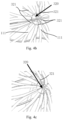
- Fig. 3 shows the medical instrument in a configuration where it has been released with a stent trailing section being unanchored according to an embodiment of the present invention.
- the medical instrument 1000 includes a stent 100, a delivery device 200 and a constraining structure 300.
- the stent 100 has a first proximal end and an opposing first distal end.
- the stent 100 is configured to be closed at the first proximal end and open at the first distal end.
- a trailing section at the first distal end includes a number of protrusions 111.
- the present invention is not limited to any particular shape of the protrusions 111, and non-limiting examples thereof include a serrated shape.
- the stent 100 further includes a proximal fixation member 120 disposed at the first proximal end to close the stent at this end.
- the stent 100 further includes a distal fixation member 130 and a pull mechanism 140.
- the pull mechanism 140 includes a number of pull elements 141.
- the present invention is not limited to any particular number of the pull elements 141, as long as the stent can be pulled at the first distal end and thus collapsed around this end.
- the number of the pull elements 141 may be less than, equal to or greater than that of the protrusions 111.
- the number of the pull elements 141 is equal to the number of the protrusions 111.
- each of the pull elements 141 is connected, at a first end thereof, to the distal fixation member 130 and, at a second end thereof, to the first distal end.
- the delivery device 200 includes a hollow push tube 210 and a hollow pull tube 220.
- a distal end of the hollow push tube 210 is detachably coupled to the first proximal end of the stent 100, more preferably to the proximal fixation member 120.
- the present invention is not particularly limited to how the coupling is established.
- the distal end of the hollow push tube 210 may be threadedly coupled to the proximal fixation member 120.
- the hollow pull tube 220 acts as drive component. It is inserted through the hollow push tube 210 and is detachably coupled within the stent 100 to the first distal end thereof.
- the hollow pull tube 220 is inserted sequentially through the hollow push tube 210 and the proximal fixation member 120 and then detachably coupled to the distal fixation member 130.
- the present invention is not particularly limited to how the detachable coupling is established.
- the hollow pull tube 220 may be threadedly coupled at a distal end thereof to the distal fixation member 130.
- the stent 100 further includes a hollow guide member 150 proximally fixed to the first proximal end of the stent 100.
- the hollow guide member 150 may be proximally fixed to the proximal fixation member 120 and arranged in coaxiality with the proximal fixation member 120 in order to allow the distal fixation member 130 and at least part of the pull mechanism 140 be inserted into the hollow guide member 150 from a distal end thereof. This facilitates control of the orientation and direction of the stent 100 when it is deformed for easier retrieval. Additionally, the hollow pull tube 220 is inserted through the proximal fixation member 120 into the hollow guide member 150 and detachably coupled to the distal fixation member 130.
- the distal fixation member 130 will be driven to move toward the proximal fixation member 120 and then cause inward collapse of the stent 100 around the first distal end by acting on the pull mechanism 140.
- all the protrusions 111 may come closer to, or even into abutment against, one another.
- a body 310 of the constraining structure 300 is passed through the hollow push tube 210 and the stent 100 and then out of the stent 100 from the first distal end thereof. More specifically, the body 310 is sequentially passed through the hollow push tube 210, the proximal fixation member 120, the hollow guide member 150 and the distal fixation member 130 and then out of the stent 100 from the first distal end thereof so that a clamping mechanism 320 at a distal end of the body 310 is disposed outside the first distal end.
- the clamping mechanism 320 is configured for insertion into all or some of the protrusions 111 on the trailing section of the stent 100, which can limit relative movement of the protrusions 111 and constrain the stent's trailing section.
- the constraining structure 300 includes the body 310 and the clamping mechanism 320 disposed at the distal end of the body 310.
- the clamping mechanism 320 includes plurality of, e.g., two, three, four, five or even more, clamping members 321. Referring to Figs. 2 and 3 , the clamping mechanism 320 includes a plurality of clamping members 321 inserted into some or all of the protrusions 111 to retain the trailing section of the stent that has been collapsed at the first distal end, preventing relative movement of all the protrusions 111 at the first distal end and thereby making them impossible to undesirably tangle with one another.
- the constraining structure and the hollow push tube when both loaded within the delivery sheath will not move relative to each other, facilitating shape control of the stent by an operator for easier delivery and retrieval.
- the hollow pull tube 220 may be manipulated to slightly collapse the stent 100 around the first distal end thereof so that the stent 100 collapsed at the first distal end can be placed into the delivery sheath.
- the constraining structure 300 is passed into the stent 100 until the clamping mechanism 320 comes out of the stent 100 from the first distal end thereof, and the clamping mechanism 320 is then manipulated to engage and thereby firmly constrain the trailing section by virtue of its own structure, thus maintaining it in the collapsed configuration.
- the operator does not need to manipulate the hollow pull tube 220 anymore, allowing it to move relative to the hollow push tube 210 to mitigate deformation of the stent in the delivery sheath. In this way, for example, as shown in Fig. 3 , the deformed stent's orientation and direction are well controlled.
- the constraining structure 300 may still constrain the stent's trailing section until the stent 100 is tuned to a desired target site. Following that, the body 310 of the constraining structure 300 may be pulled proximally so that the clamping mechanism 320 is expanded or deformed to no longer constrain the trailing section of the stent. Since this trailing section is elastic, it will self-expand by virtue of the resilience. As a result, anchoring features 112 on the stent are directed toward and then penetrate the LAA wall.
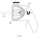
- Figs. 5a to 5c A more detailed description is given below with reference to Figs. 5a to 5c .
- the hollow push tube 210 can be manipulated to adjust the position of the stent 100, for example, by moving it forth and back along the direction indicated by the arrow A, or by rotating it along the direction indicated by the arrow B, until it is positioned as desired.
- the clamping mechanism 320 can be removed simply by pulling the constraining structure 300 gently by the operator.
- the trailing section of the stent 100 is freed, and the anchoring features 112 are enabled to penetrate the LAA wall.
- the constraining structure 300 may be withdrawn along the direction indicated by the arrow C.
- the operator may successively withdraw the constraining structure 300, the hollow push tube 210 and the hollow pull tube 220 from the human body, accomplishing the closure of the LAA.
- the clamping members 321 are preferably wire-like members with sufficient strength and desirable deformability, which enable firm clamping while allowing successful release by virtue of elastic deformation.
- the clamping members 321 may be made of an elastic material or a shape memory material, which imparts excellent deformability and sufficient mechanical properties to the clamping mechanism 320.
- the material of the clamping members 321 may be selected from a nickel-titanium alloy or stainless steel. More preferably, the clamping members 321 are nickel-titanium wires, optionally round nickel-titanium wires with a diameter optionally of 0.15 mm. Such nickel-titanium wires have sufficient stiffness and good deformability and allow a reduced size during delivery.
- the present invention is not limited to any particular number of such clamping members 321, and the number may be determined depending on the size of the stent's trailing section. How the clamping members 321 retain the stent's trailing section will be described in greater detail below in the context of 10 protrusions 111 being provided on the trailing section of the stent 100, as an example.
- the clamping mechanism 320 may include two wires each having a shape resembling the letter "C" and crossing each other.
- the wires may provide two C-shaped clamping members 321 each defining two hooked fingers.
- the four hooked fingers may pass through and engage some of the protrusions 111.
- the clamping mechanism 320 may include five wires, each of which may be curved at one end to provide one clamping member 321.
- the five clamping members 321 formed by the wires may be spaced apart circumferentially and function like similar hooked fingers which may pass through and engage some of the protrusions 111. In this way, all the protrusions can also be effectively retained and prevented from relative movement.
- the clamping mechanism 320 may include ten wires. With similarity to the variant shown in Fig. 4b , each of the wires may be curved at one end to provide one clamping member 321, and the ten clamping members 321 may be spaced apart circumferentially and function like similar hooked fingers. However, in this case, all the protrusions 111 are populated and retained by the respective hooked fingers.
- each clamping member 321 may be shaped like the letter "V" and define two hooked fingers.
- the clamping mechanism 320 may include only one clamping member 321 which is C-shaped or V-shaped, for example. Some of the protrusions 111 can be retained by passing the two hooked fingers of the clamping members 321 respectively into them.
- the clamping mechanism 320 may include a plurality of clamping members 321. In these cases, the clamping members 321 may each define either one or two hooked fingers and may be used in combination. In the case of only one hooked finger, each clamping member 321 may be situated outside the stent 100 at one end and pass through one of the protrusions 111 at the other end. Moreover, the individual clamping members 321 may pass through different protrusions.
- each protrusion 111 is a hollow structure defining an opening, through which one end of a clamping member 321 can pass to engage the stent 100.
- the clamping member may define two hooked fingers, and the number of the hooked fingers is smaller than the number of the protrusions.
- each clamping member 321 may define one hooked finger, and the number of the hooked fingers is smaller than or equal to that of the protrusions. That is, the number of the clamping members is smaller than or equal to the number of the protrusions.
- the number of the clamping members 321 is equal to that of the protrusions 111 so that the protrusions 111 can be populated with the respective clamping members 321, as shown in Fig. 4c .
- the number of the clamping members 321 is less than the number of the protrusions 111.
- the number of the protrusions 111 is twice that of the clamping members 321.
- the former may be 10, and the latter may be accordingly 5. This can reduce the size of the clamping mechanism 320, allowing a smaller size during delivery.
- the protrusions may be populated by the clamping members 321 so that there are one or more unpopulated protrusions between every two adjacent populated protrusions.
- more clamping members 321 with a smaller diameter may be provided.
- the number of the clamping members 321 is four or five, they may be made of round nickel-titanium wires with a diameter of 0.15 mm.
- ten clamping members 321 when ten clamping members 321 are provided, they may be nickel-titanium wires with a diameter of 0.04 mm.
- Fig. 6 shows another embodiment of the constraining structure 300, in which a single clamping member 321' is included.
- the clamping member 321' may pass through either all or spaced ones of the protrusions. With 8 protrusions being provided as an example, the clamping members 321' may pass through the first, second, third, fifth, sixth and seventh protrusions clockwise, with the fourth and eight protrusions being unpopulated. Additionally, the clamping member 321' may be generally C-like or helical in shape. The C-like shape may have an opening. The present invention is not limited to any particular size of the opening, as long as all the protrusions can be effectively gathered and retained.
- the clamping members 321' is preferably an elastic wire such as a nickel-titanium wire or another nickel-based alloy wire. In operation, the clamping member 321' can be removed to release the stent's trailing section simply by gently pulling or turning the body 310. Therefore, it is convenient to operate.
- the present invention is not limited to any particular method of fabricating the constraining structure 300, and the fabrication can be accomplished in various ways.
- the body 310 may be made as a straight rod, and the clamping mechanism 320 can be obtained by welding or otherwise attaching a number of wires (e.g., those as shown in Figs. 4a to 4c ) to a distal end of the straight rod.
- a number of wires may be each curved at one end and retained in a sleeve.
- the sleeve may be configured as the body 310.
- the body 310 may be provided as a thick tube or wire, and a number of wires may be formed at its one end by cutting or otherwise. These wires may be then curved to form the clamping mechanism 320.
- each clamping member 321 may be curved relative to the body 310 at an angle preferably of 30°-180°, with 53°-72° being more preferred.
- the inventors have found from experiments that an angle of curvature of each clamping member 321 in that range can allow both effective retention and easy release.
- the angle of curvature is defined as an angle of curvature of each clamping member 321 relative to the positive direction of the axis of the body 310.
- the stent 100 may further includes a biocompatible membrane covering part of an outer surface of the stent 100, with the protrusions being exposed therefrom.
- the present application also contemplates other structural variants of the clamping members.
- the stent may be either a braided stent or a cut stent, without limiting the present invention.
- the constraining structure of the present invention can desirably constrain the stent's trailing section so that the stent is deformed in a controlled manner and can be easily delivered within the delivery sheath while being able to easily expand upon it being pushed out thereof. Additionally, tangling of the stent's trailing section is prevented, ensuring a good success rate in release of the stent that has been pushed out of the sheath. Further, according to the present invention, after the stent is pushed out of the sheath, the anchoring features on the stent will not immediately anchor to the LAA wall. This can avoid damage to the patient's LAA wall caused by an operational error of the operator and reduce the risk of an accumulated pericardial effusion during surgery.
Landscapes
- Health & Medical Sciences (AREA)
- Life Sciences & Earth Sciences (AREA)
- Surgery (AREA)
- Biomedical Technology (AREA)
- Veterinary Medicine (AREA)
- Engineering & Computer Science (AREA)
- Heart & Thoracic Surgery (AREA)
- Vascular Medicine (AREA)
- Animal Behavior & Ethology (AREA)
- General Health & Medical Sciences (AREA)
- Public Health (AREA)
- Cardiology (AREA)
- Medical Informatics (AREA)
- Reproductive Health (AREA)
- Nuclear Medicine, Radiotherapy & Molecular Imaging (AREA)
- Molecular Biology (AREA)
- Oral & Maxillofacial Surgery (AREA)
- Transplantation (AREA)
- Media Introduction/Drainage Providing Device (AREA)
- Prostheses (AREA)
Claims (12)
- Medizinisches Instrument (1000), das einen Stent (100) umfasst, der ein proximales Ende und ein entgegengesetztes distales Ende aufweist, wobei das distale Ende des Stents (100) mit einer ausgedehnten Konfiguration und einer zusammengefallenen Konfiguration konfiguriert ist, wobei eine hintere Sektion des Stents (100) an dem distalen Ende eine Vielzahl von Vorsprüngen (111) umfasst und wobei das medizinische Instrument (1000) ferner eine einengende Struktur (300) umfasst, die einen Körper (310) und einen Klemmmechanismus (320) umfasst, wobei der Klemmmechanismus (320) an einem distalen Ende des Körpers (310) angeordnet ist, wobei sich der Körper (310) von dem proximalen Ende des Stents (100) bis zu dem distalen Ende des Stents (100) erstreckt, wobei der Klemmmechanismus (320) durch Hindurchgehen durch alle oder einige der Vorsprünge (111) eine relative Bewegung der Vorsprünge (111) begrenzt,
dadurch gekennzeichnet, dassdas medizinische Instrument (1000) ferner ein proximales Fixierungselement (120) umfasst, das an dem proximalen Ende des Stents (100) angeordnet und dafür konfiguriert ist, den Stent (100) in eine geschlossene Konfiguration an dem proximalen Ende zu bringen,und dadurch, dassdas medizinische Instrument (1000) ferner ein distales Fixierungselement (130) und einen Zugmechanismus (140) umfasst, wobei der Zugmechanismus (140) eine Anzahl von Zugelementen (141) umfasst, die jeweils, an einem ersten Ende, mit dem distalen Fixierungselement (130) und, an einem zweiten Ende, mit dem distalen Ende des Stents (100) verbunden sind, wobei das distale Fixierungselement (130) dafür konfiguriert ist, hin zu dem proximalen Fixierungselement (120) beweglich zu sein, so dass ermöglicht wird, dass das distale Ende des Stents (100) von der ausgedehnten Konfiguration zu der zusammengefallenen Konfiguration wechselt. - Medizinisches Instrument (1000) nach Anspruch 1, wobei der Klemmmechanismus (320) ein einzelnes Klemmelement (321) umfasst, das entweder nacheinander durch alle Vorsprünge (111) oder durch voneinander beabstandete der Vorsprünge (111) hindurchgeht.
- Medizinisches Instrument (1000) nach Anspruch 1, wobei der Klemmmechanismus (320) mindestens ein Klemmelement (321) umfasst, das jeweils an entgegengesetzten Enden durch unterschiedliche der Vorsprünge (111) hindurchgeht.
- Medizinisches Instrument (1000) nach Anspruch 1, wobei der Klemmmechanismus (320) eine Vielzahl von Klemmelementen (321) umfasst, die umlaufend um den Stent (100) angeordnet sind, wobei jedes der Klemmelemente (321) an einem Ende des Klemmelements (321) durch einen der Vorsprünge (111) hindurchgeht, wobei die Klemmelemente (321) durch unterschiedliche der Vorsprünge (111) hindurchgehen.
- Medizinisches Instrument (1000) nach Anspruch 4, wobei eine Anzahl der Klemmelemente (321) kleiner als oder so groß wie eine Anzahl der Vorsprünge (111) ist.
- Medizinisches Instrument (1000) nach Anspruch 5, wobei die Anzahl der Vorsprünge (111) das Zweifache der Anzahl der Klemmelemente (321) beträgt.
- Medizinisches Instrument (1000) nach einem der Ansprüche 2 bis 4, wobei das Klemmelement (321) ein drahtartiges Element ist, das aus einem elastischen Material hergestellt ist.
- Medizinisches Instrument (1000) nach Anspruch 7, wobei ein Material des drahtartigen Elements eine Nickel-Titan-Legierung oder rostfreier Stahl ist.
- Medizinisches Instrument (1000) nach Anspruch 2 oder 3, wobei das Klemmelement (321) als ein Buchstabe "C" oder "V" geformt ist.
- Medizinisches Instrument (1000) nach Anspruch 3 oder 4, wobei jedes von dem/den Klemmelement(en) (321) im Verhältnis zu dem Körper (310) in einem Winkel gekrümmt ist, der von 30° bis 180° reicht.
- Medizinisches Instrument (1000) nach Anspruch 1, das ferner eine biologisch verträgliche Membran umfasst, die einen Teil einer Oberfläche des Stents (100) so bedeckt, dass die Vorsprünge (111) von derselben freigelegt sind.
- Medizinisches Instrument (1000) nach Anspruch 1, das ferner eine Zuführungseinrichtung (200) umfasst, die eine hohle Schubröhre (210) und eine Antriebskomponente umfasst, wobei die hohle Schubröhre (210) an einem distalen Ende der hohlen Schubröhre (210) lösbar mit dem proximalen Ende des Stents (100) verbunden ist, wobei die Antriebskomponente durch die hohle Schubröhre (210) in den Stent (100) eingesetzt und innerhalb des Stents (100) lösbar mit dem distalen Ende des Stents (100) verbunden ist, um so zu veranlassen, dass das distale Ende des Stents (100) von der ausgedehnten Konfiguration zu der zusammengefallenen Konfiguration wechselt, wobei sich der Körper (310) von dem proximalen Ende des Stents (100) durch die hohle Schubröhre (210) bis zu dem distalen Ende des Stents (100) erstreckt.
Applications Claiming Priority (2)
| Application Number | Priority Date | Filing Date | Title |
|---|---|---|---|
| CN201911032196.1A CN112716554B (zh) | 2019-10-28 | 2019-10-28 | 医疗器械 |
| PCT/CN2020/122019 WO2021082974A1 (zh) | 2019-10-28 | 2020-10-20 | 医疗器械 |
Publications (4)
| Publication Number | Publication Date |
|---|---|
| EP4035608A1 EP4035608A1 (de) | 2022-08-03 |
| EP4035608A4 EP4035608A4 (de) | 2022-11-23 |
| EP4035608C0 EP4035608C0 (de) | 2025-03-12 |
| EP4035608B1 true EP4035608B1 (de) | 2025-03-12 |
Family
ID=75588854
Family Applications (1)
| Application Number | Title | Priority Date | Filing Date |
|---|---|---|---|
| EP20882016.7A Active EP4035608B1 (de) | 2019-10-28 | 2020-10-20 | Medizinisches instrument |
Country Status (4)
| Country | Link |
|---|---|
| US (1) | US12239324B2 (de) |
| EP (1) | EP4035608B1 (de) |
| CN (1) | CN112716554B (de) |
| WO (1) | WO2021082974A1 (de) |
Families Citing this family (8)
| Publication number | Priority date | Publication date | Assignee | Title |
|---|---|---|---|---|
| US11399842B2 (en) | 2013-03-13 | 2022-08-02 | Conformal Medical, Inc. | Devices and methods for excluding the left atrial appendage |
| EP2968878B1 (de) | 2013-03-13 | 2020-08-12 | Conformal Medical, Inc. | Vorrichtungen zum ausschluss des linken vorhofanhangs |
| WO2018081466A2 (en) | 2016-10-27 | 2018-05-03 | Conformal Medical, Inc. | Devices and methods for excluding the left atrial appendage |
| US11426172B2 (en) | 2016-10-27 | 2022-08-30 | Conformal Medical, Inc. | Devices and methods for excluding the left atrial appendage |
| US12144508B2 (en) | 2019-02-08 | 2024-11-19 | Conformal Medical, Inc. | Devices and methods for excluding the left atrial appendage |
| CN118717212A (zh) | 2019-02-08 | 2024-10-01 | 保形医疗公司 | 用于除去左心耳的装置 |
| CN114041896B (zh) * | 2021-12-21 | 2024-05-07 | 启晨(上海)医疗器械有限公司 | 气道阻塞装置 |
| CN119074103A (zh) * | 2024-08-15 | 2024-12-06 | 上海形状记忆合金材料有限公司 | 一种心血管介入封堵器输送系统 |
Family Cites Families (13)
| Publication number | Priority date | Publication date | Assignee | Title |
|---|---|---|---|---|
| US7988724B2 (en) * | 2003-12-23 | 2011-08-02 | Sadra Medical, Inc. | Systems and methods for delivering a medical implant |
| US7758626B2 (en) | 2004-07-20 | 2010-07-20 | Medtronic Vascular, Inc. | Device and method for delivering an endovascular stent-graft having a longitudinally unsupported portion |
| US8764772B2 (en) * | 2008-02-21 | 2014-07-01 | Cook Medical Technologies Llc | Occlusion device |
| US9192497B2 (en) * | 2008-09-05 | 2015-11-24 | Cook Medical Technologies Llc | Apparatus and methods for improved stent deployment |
| JP5607639B2 (ja) * | 2008-10-10 | 2014-10-15 | サドラ メディカル インコーポレイテッド | 医療用デバイス・システム |
| US10064628B2 (en) * | 2009-06-17 | 2018-09-04 | Coherex Medical, Inc. | Medical device for modification of left atrial appendage and related systems and methods |
| US20110054515A1 (en) * | 2009-08-25 | 2011-03-03 | John Bridgeman | Device and method for occluding the left atrial appendage |
| US9561102B2 (en) * | 2010-06-02 | 2017-02-07 | Medtronic, Inc. | Transcatheter delivery system and method with controlled expansion and contraction of prosthetic heart valve |
| US10603197B2 (en) | 2013-11-19 | 2020-03-31 | Endospan Ltd. | Stent system with radial-expansion locking |
| WO2016016899A1 (en) * | 2014-07-30 | 2016-02-04 | Mitraltech Ltd. | Articulatable prosthetic valve |
| CN104688292B (zh) * | 2015-02-15 | 2017-08-25 | 上海形状记忆合金材料有限公司 | 一种左心耳封堵装置及封堵系统 |
| WO2016183523A1 (en) | 2015-05-14 | 2016-11-17 | Cephea Valve Technologies, Inc. | Cardiac valve delivery devices and systems |
| CN108236479A (zh) * | 2016-12-26 | 2018-07-03 | 上海微创医疗器械(集团)有限公司 | 左心耳封堵系统、左心耳封堵器及其输送器 |
-
2019
- 2019-10-28 CN CN201911032196.1A patent/CN112716554B/zh active Active
-
2020
- 2020-10-20 WO PCT/CN2020/122019 patent/WO2021082974A1/zh not_active Ceased
- 2020-10-20 US US17/772,320 patent/US12239324B2/en active Active
- 2020-10-20 EP EP20882016.7A patent/EP4035608B1/de active Active
Also Published As
| Publication number | Publication date |
|---|---|
| US20220401112A1 (en) | 2022-12-22 |
| EP4035608A1 (de) | 2022-08-03 |
| EP4035608C0 (de) | 2025-03-12 |
| WO2021082974A1 (zh) | 2021-05-06 |
| EP4035608A4 (de) | 2022-11-23 |
| CN112716554B (zh) | 2023-03-24 |
| CN112716554A (zh) | 2021-04-30 |
| US12239324B2 (en) | 2025-03-04 |
Similar Documents
| Publication | Publication Date | Title |
|---|---|---|
| EP4035608B1 (de) | Medizinisches instrument | |
| US11207073B2 (en) | Tissue ligation devices and methods therefor | |
| US20240252176A1 (en) | Tissue ligation devices and controls therefor | |
| US11096682B2 (en) | Surgical instrument for manipulating and passing suture | |
| US8034075B2 (en) | Tethered coil for treatment of body lumens | |
| US12102328B2 (en) | Left atrial appendage occluder and left atrial appendage occlusion system | |
| US12343251B2 (en) | Controllable guiding device for implantable apparatus | |
| JP2024506717A (ja) | 心臓の病状を治療するためのデバイス、システム、および方法 | |
| JP2009532123A (ja) | 可変長の卵円孔開存(pfo)オクルーダ及びキャッチシステム | |
| CN113286550A (zh) | 封堵器插入系统 | |
| CN114469212B (zh) | 限位装置和缝合装置 | |
| WO2025122803A1 (en) | Devices, systems, and methods for treating conditions of the heart |
Legal Events
| Date | Code | Title | Description |
|---|---|---|---|
| STAA | Information on the status of an ep patent application or granted ep patent |
Free format text: STATUS: THE INTERNATIONAL PUBLICATION HAS BEEN MADE |
|
| PUAI | Public reference made under article 153(3) epc to a published international application that has entered the european phase |
Free format text: ORIGINAL CODE: 0009012 |
|
| STAA | Information on the status of an ep patent application or granted ep patent |
Free format text: STATUS: REQUEST FOR EXAMINATION WAS MADE |
|
| 17P | Request for examination filed |
Effective date: 20220429 |
|
| AK | Designated contracting states |
Kind code of ref document: A1 Designated state(s): AL AT BE BG CH CY CZ DE DK EE ES FI FR GB GR HR HU IE IS IT LI LT LU LV MC MK MT NL NO PL PT RO RS SE SI SK SM TR |
|
| A4 | Supplementary search report drawn up and despatched |
Effective date: 20221024 |
|
| RIC1 | Information provided on ipc code assigned before grant |
Ipc: A61F 2/24 20060101ALI20221018BHEP Ipc: A61B 17/12 20060101AFI20221018BHEP |
|
| DAV | Request for validation of the european patent (deleted) | ||
| DAX | Request for extension of the european patent (deleted) | ||
| GRAP | Despatch of communication of intention to grant a patent |
Free format text: ORIGINAL CODE: EPIDOSNIGR1 |
|
| STAA | Information on the status of an ep patent application or granted ep patent |
Free format text: STATUS: GRANT OF PATENT IS INTENDED |
|
| INTG | Intention to grant announced |
Effective date: 20241029 |
|
| GRAS | Grant fee paid |
Free format text: ORIGINAL CODE: EPIDOSNIGR3 |
|
| GRAA | (expected) grant |
Free format text: ORIGINAL CODE: 0009210 |
|
| STAA | Information on the status of an ep patent application or granted ep patent |
Free format text: STATUS: THE PATENT HAS BEEN GRANTED |
|
| AK | Designated contracting states |
Kind code of ref document: B1 Designated state(s): AL AT BE BG CH CY CZ DE DK EE ES FI FR GB GR HR HU IE IS IT LI LT LU LV MC MK MT NL NO PL PT RO RS SE SI SK SM TR |
|
| REG | Reference to a national code |
Ref country code: GB Ref legal event code: FG4D |
|
| REG | Reference to a national code |
Ref country code: CH Ref legal event code: EP |
|
| REG | Reference to a national code |
Ref country code: DE Ref legal event code: R096 Ref document number: 602020047733 Country of ref document: DE |
|
| REG | Reference to a national code |
Ref country code: IE Ref legal event code: FG4D |
|
| U01 | Request for unitary effect filed |
Effective date: 20250321 |
|
| U07 | Unitary effect registered |
Designated state(s): AT BE BG DE DK EE FI FR IT LT LU LV MT NL PT RO SE SI Effective date: 20250327 |
|
| PG25 | Lapsed in a contracting state [announced via postgrant information from national office to epo] |
Ref country code: RS Free format text: LAPSE BECAUSE OF FAILURE TO SUBMIT A TRANSLATION OF THE DESCRIPTION OR TO PAY THE FEE WITHIN THE PRESCRIBED TIME-LIMIT Effective date: 20250612 |
|
| PG25 | Lapsed in a contracting state [announced via postgrant information from national office to epo] |
Ref country code: ES Free format text: LAPSE BECAUSE OF FAILURE TO SUBMIT A TRANSLATION OF THE DESCRIPTION OR TO PAY THE FEE WITHIN THE PRESCRIBED TIME-LIMIT Effective date: 20250312 |
|
| PG25 | Lapsed in a contracting state [announced via postgrant information from national office to epo] |
Ref country code: NO Free format text: LAPSE BECAUSE OF FAILURE TO SUBMIT A TRANSLATION OF THE DESCRIPTION OR TO PAY THE FEE WITHIN THE PRESCRIBED TIME-LIMIT Effective date: 20250612 |
|
| PG25 | Lapsed in a contracting state [announced via postgrant information from national office to epo] |
Ref country code: HR Free format text: LAPSE BECAUSE OF FAILURE TO SUBMIT A TRANSLATION OF THE DESCRIPTION OR TO PAY THE FEE WITHIN THE PRESCRIBED TIME-LIMIT Effective date: 20250312 |
|
| PG25 | Lapsed in a contracting state [announced via postgrant information from national office to epo] |
Ref country code: GR Free format text: LAPSE BECAUSE OF FAILURE TO SUBMIT A TRANSLATION OF THE DESCRIPTION OR TO PAY THE FEE WITHIN THE PRESCRIBED TIME-LIMIT Effective date: 20250613 |
|
| PG25 | Lapsed in a contracting state [announced via postgrant information from national office to epo] |
Ref country code: SM Free format text: LAPSE BECAUSE OF FAILURE TO SUBMIT A TRANSLATION OF THE DESCRIPTION OR TO PAY THE FEE WITHIN THE PRESCRIBED TIME-LIMIT Effective date: 20250312 |
|
| PG25 | Lapsed in a contracting state [announced via postgrant information from national office to epo] |
Ref country code: PL Free format text: LAPSE BECAUSE OF FAILURE TO SUBMIT A TRANSLATION OF THE DESCRIPTION OR TO PAY THE FEE WITHIN THE PRESCRIBED TIME-LIMIT Effective date: 20250312 |
|
| PG25 | Lapsed in a contracting state [announced via postgrant information from national office to epo] |
Ref country code: CZ Free format text: LAPSE BECAUSE OF FAILURE TO SUBMIT A TRANSLATION OF THE DESCRIPTION OR TO PAY THE FEE WITHIN THE PRESCRIBED TIME-LIMIT Effective date: 20250312 |
|
| PG25 | Lapsed in a contracting state [announced via postgrant information from national office to epo] |
Ref country code: SK Free format text: LAPSE BECAUSE OF FAILURE TO SUBMIT A TRANSLATION OF THE DESCRIPTION OR TO PAY THE FEE WITHIN THE PRESCRIBED TIME-LIMIT Effective date: 20250312 |
|
| PG25 | Lapsed in a contracting state [announced via postgrant information from national office to epo] |
Ref country code: IS Free format text: LAPSE BECAUSE OF FAILURE TO SUBMIT A TRANSLATION OF THE DESCRIPTION OR TO PAY THE FEE WITHIN THE PRESCRIBED TIME-LIMIT Effective date: 20250712 |
|
| U20 | Renewal fee for the european patent with unitary effect paid |
Year of fee payment: 6 Effective date: 20251028 |