EP4035580A1 - Toilet seat device - Google Patents
Toilet seat device Download PDFInfo
- Publication number
- EP4035580A1 EP4035580A1 EP20869987.6A EP20869987A EP4035580A1 EP 4035580 A1 EP4035580 A1 EP 4035580A1 EP 20869987 A EP20869987 A EP 20869987A EP 4035580 A1 EP4035580 A1 EP 4035580A1
- Authority
- EP
- European Patent Office
- Prior art keywords
- toilet
- toilet seat
- image sensor
- image
- open
- Prior art date
- Legal status (The legal status is an assumption and is not a legal conclusion. Google has not performed a legal analysis and makes no representation as to the accuracy of the status listed.)
- Withdrawn
Links
Images








Classifications
-
- A—HUMAN NECESSITIES
- A47—FURNITURE; DOMESTIC ARTICLES OR APPLIANCES; COFFEE MILLS; SPICE MILLS; SUCTION CLEANERS IN GENERAL
- A47K—SANITARY EQUIPMENT; ACCESSORIES THEREFOR, e.g. TOILET ACCESSORIES
- A47K13/00—Seats or covers for all kinds of closets
- A47K13/24—Parts or details not covered in, or of interest apart from, groups A47K13/02 - A47K13/22
-
- A—HUMAN NECESSITIES
- A61—MEDICAL OR VETERINARY SCIENCE; HYGIENE
- A61B—DIAGNOSIS; SURGERY; IDENTIFICATION
- A61B10/00—Instruments for taking body samples for diagnostic purposes; Other methods or instruments for diagnosis, e.g. for vaccination diagnosis, sex determination or ovulation-period determination; Throat striking implements
- A61B10/0038—Devices for taking faeces samples; Faecal examination devices
-
- A—HUMAN NECESSITIES
- A61—MEDICAL OR VETERINARY SCIENCE; HYGIENE
- A61B—DIAGNOSIS; SURGERY; IDENTIFICATION
- A61B5/00—Measuring for diagnostic purposes; Identification of persons
- A61B5/20—Measuring for diagnostic purposes; Identification of persons for measuring urological functions restricted to the evaluation of the urinary system
- A61B5/207—Sensing devices adapted to collect urine
-
- A—HUMAN NECESSITIES
- A61—MEDICAL OR VETERINARY SCIENCE; HYGIENE
- A61B—DIAGNOSIS; SURGERY; IDENTIFICATION
- A61B5/00—Measuring for diagnostic purposes; Identification of persons
- A61B5/68—Arrangements of detecting, measuring or recording means, e.g. sensors, in relation to patient
- A61B5/6887—Arrangements of detecting, measuring or recording means, e.g. sensors, in relation to patient mounted on external non-worn devices, e.g. non-medical devices
- A61B5/6891—Furniture
-
- A—HUMAN NECESSITIES
- A61—MEDICAL OR VETERINARY SCIENCE; HYGIENE
- A61B—DIAGNOSIS; SURGERY; IDENTIFICATION
- A61B5/00—Measuring for diagnostic purposes; Identification of persons
- A61B5/42—Detecting, measuring or recording for evaluating the gastrointestinal, the endocrine or the exocrine systems
- A61B5/4222—Evaluating particular parts, e.g. particular organs
- A61B5/4255—Intestines, colon or appendix
-
- H—ELECTRICITY
- H04—ELECTRIC COMMUNICATION TECHNIQUE
- H04N—PICTORIAL COMMUNICATION, e.g. TELEVISION
- H04N23/00—Cameras or camera modules comprising electronic image sensors; Control thereof
- H04N23/57—Mechanical or electrical details of cameras or camera modules specially adapted for being embedded in other devices
Definitions
- the present disclosure relates to a toilet seat device.
- Priority is claimed on Japanese Patent Application No. 2019-173282, filed September 24, 2019 and Japanese Patent Application No. 2020-083273, filed May 11, 2020 , and the entire disclosure of the Japanese Patent Applications are hereby incorporated by reference herein.
- Patent Document 1 a toilet bowl in which a camera is arranged on the toilet bowl so as to capture a pooled water portion of the toilet bowl in which excrement is located is disclosed.
- Patent Document 1 Japanese Unexamined Patent Application, First Publication No. 2007-252805
- a toilet seat device measures for preventing a human body from being captured are insufficient. That is, there is a demand for a toilet seat device that physically realizes that the human body is not photobombed in the captured image such that the user can use the toilet seat device at ease, and there is room for improvement in that respect.
- the present disclosure provides a toilet seat device configured to capture a target image in consideration of the privacy of the user such that the user can use at ease.
- a toilet device includes a toilet seat disposed on an upper side of a toilet; an image sensor provided on a back surface of the toilet seat and configured to image an inner space of a toilet bowl at time of excretion; an open-close acquiring unit configured to acquire open-close information of the toilet seat; and an imaging control unit configured to determine whether or not to image by the image sensor according to the open-close information of the toilet seat acquired by the open-close acquiring unit.
- a toilet device includes a toilet seat disposed on an upper side of a toilet; an image sensor provided individually from the toilet seat and on a lower side of the toilet seat, the image sensor being configured to image an inner space of a toilet bowl at the time of excretion; an open-close acquiring unit configured to acquire open-close information of the toilet seat; and an imaging control unit configured to determine whether or not to image by the image sensor according to the open-close information of the toilet seat acquired by the open-close acquiring unit.
- a toilet seat device 1 includes a toilet 10, a toilet seat 12, a toilet lid, and an image determination device 2.
- the toilet 10 has a toilet bowl 11.
- the toilet seat 12 is provided to be openable and closable with respect to the toilet 10.
- the toilet lid is provided to be openable and closable with respect to the toilet seat 12.
- the toilet lid is not shown in figures.
- the image determination device 2 is configured to acquire an image of a stool G excreted by a user, and determines a state of the stool G or the like based on the acquired image.
- Fig. 1 is a perspective view of the toilet seat device 1 viewed from diagonally upper side thereof, and is a view in which a part of the toilet seat is broken.
- the toilet seat 12 in a closed state is shown.
- the toilet lid in the closed state covers an opening 11a of the toilet bowl 11 shown in Fig. 4 from the upper side with the toilet seat 12 sandwiched therebetween.
- a side in front of the user of the toilet seat device 1 is referred to as a front side in a state in which the user sits on the toilet seat 12.
- a side behind the user is referred to as called the rear side.
- a direction connecting the front side and the rear side is referred to as a front-rear direction X1.
- a left side viewed from the user sitting on the toilet seat 12 is referred to as a "left side”
- a right side is referred to as a "right side”.
- a direction connecting the left side and the right side is referred to as a left-right direction X2.
- a side away from a floor surface on which the toilet seat device 1 is disposed is referred to as an "upper side", and a side closer to the floor surface is referred to as a “lower side”.
- a direction connecting the upper side and the lower side is referred to as a vertical direction X3.
- a rim is provided on an upper surface 11b of the opening 11a of the toilet bowl 11.
- the rim projects toward an inner space of the toilet bowl 11.
- a pooled water portion 11c is arranged at a bottom portion of the toilet bowl 11.
- the pooled water portion 11c is connected to a toilet drainage channel 14 for discharging the stool G from the toilet bowl 11.
- a rotation shaft O1 extending in the left-right direction X2 is provided at the rear portion of the toilet 10.
- the toilet seat 12 is configured to be freely rotatable around the rotation shaft 01.
- the toilet seat 12 is possible to enter either of a closed state or an open state by rotating as described above.
- the toilet seat 12 In the closed state, the toilet seat 12 is in contact with an upper end portion of the toilet bowl 11 and extends in both the left-right direction X2 and the front-back direction X1.
- the toilet seat 12 In the open state, the toilet seat 12 is away from the upper surface 11b of the toilet bowl 11 and extends at least in the vertical direction X3.
- the toilet seat 12 has an annular shape that extends continuously in a circumferential direction.
- the toilet seat 12 is in contact with the upper surface 11b of the toilet bowl 11 in the closed state.
- An opening size of the opening 12b of the toilet seat 12 is set to be slightly smaller than am opening size of the opening 11a of the toilet bowl 11 when viewed from the upper side.
- the toilet seat 12 projects laterally from the upper surface 11b of the toilet bowl 11 toward an inner space.
- Fig. 4 is a view showing a back surface of the toilet seat 12 when the toilet seat 12 is in the open state.
- the back surface 12a of the toilet seat 12 is provided with support members 13 projecting downward at four locations in the circumferential direction.
- the four support members 13 are configured to support the toilet seat 12 at four points with respect to the upper surface 11b of the toilet bowl 11 when the toilet seat 12 is in the closed state.
- the toilet lid that is not shown in figures is configured to be freely rotatable around a rotation axis extending in the left-right direction X2.
- the toilet lid can enter either the closed state or the open state.
- the toilet lid covers the toilet seat 12 in the closed state and extends in the left-right direction X2 and the front-back direction X1 while closing the opening of each of the toilet bowl 11 and the toilet seat 12.
- the toilet lid In the open state, the toilet lid extends at least in the vertical direction X3.
- the toilet lid is provided so as to open and close the opening of the toilet bowl 11 and the opening of the toilet seat 12.
- An image determination device 2 is provided on the back surface 12a of the toilet seat 12.
- the image determination device 2 includes an image sensor 20, an inclination sensor 21, an imaging control unit 22, and an illuminator 23.
- the image sensor 20 is provided on the back surface 12a of the toilet seat 12.
- the inclination sensor 21 acquires open-close information of the toilet seat 12.
- the inclination sensor 21 is an example of an open-close acquiring unit.
- the imaging control unit 22 controls the propriety of imaging by the image sensor 20 according to the open-close information of the toilet seat 12 acquired by the inclination sensor 21.
- the illuminator 23 emits light toward a deep side of the toilet drainage channel 14 such that the stool G that has moved from the bottom surface of the pooled water portion 11c of the toilet 10 toward the deep side, which is the downstream side of the toilet drainage channel 14, can be imaged.
- the inclination sensor 21 is accommodated in the toilet seat 12.
- the inclination sensor 21 is set to detect that the toilet seat 12 has begun to open when the toilet seat 12 is opened by a certain angle or more.
- the inclination sensor 21 can employ a sensor in which a ball is accommodated inside such that the inclination of the toilet seat 12 is detected by the movement of the ball.
- the inclination sensor 21 is set to not to detect the inclination of the toilet seat 12 when the toilet seat 12 slightly rattles and lifts.
- the inclination sensor 21 is set to react when the toilet seat 12 is opened equal to or more than a predetermined angle.
- the open-close acquiring unit may use an automatic open-close device of the toilet seat 12 as the open-close sensor besides the inclination sensor 21.
- the imaging control unit 22 is arranged on the toilet 10.
- the imaging control unit 22 is provided to be able to communicate wirelessly or by wire with the image sensor 20 and the inclination sensor 21.
- the image sensor 20 includes the control of stopping the image sensor 20 from capturing the image of the internal space (pooled water portion 11c) of the toilet bowl 11 and the control capable of deleting the image captured when it is determined that the toilet seat 12 is in the open state.
- the imaging control unit 22 may be configured to interlock with a sitting sensor such as a load sensor or the like for detecting that the user is sitting on the toilet seat 12 and control the imaging of the internal space of the toilet bowl 11 by the image sensor 20 when the sitting is detected.
- a sitting sensor such as a load sensor or the like for detecting that the user is sitting on the toilet seat 12 and control the imaging of the internal space of the toilet bowl 11 by the image sensor 20 when the sitting is detected.
- the sitting sensor is not shown in the figures.
- the image sensor 20 has a camera lens and an imaging device.
- the image sensor 20 is disposed on the back surface 12a of the toilet seat 12 and is arranged to face the toilet drainage channel opening 14a of the toilet drainage channel 14.
- the image sensor 20 is arranged such that an internal direction of the toilet drainage channel 14 to which the stool G is discharged from the pooled water portion 11c of the toilet bowl 11 can be imaged by the imaging device.
- Fig. 6 is a plan view of the toilet 10 of the toilet seat device 1 as viewed from above.
- the toilet seat is not shown.
- the image sensor 20 is arranged in front of the pooled water portion 11c.
- the image sensor 20 is arranged at a position where the deep side (rear side) of the toilet drainage channel opening 14a as an entrance of the toilet drainage channel 14 can be captured.
- a sensor arrangement region R of the image sensor 20 of the toilet seat device 1 is a range from the front region of the toilet seat to the lateral region of the toilet seat between the left side and the right side thereof, and is a left-right symmetrical region sandwiching the center of the left-right direction X2.
- the front region of the toilet seat is a region in which the stool G that has entered the toilet drainage channel opening 14a of the toilet bowl 11 can be easily seen.
- the lateral region of the toilet seat is a region where the opening 14a of the toilet drainage channel of the toilet bowl 11 can be peeped into, and it is possible to avoid the human body from being photobombed in a view angle (view field 20A) of the image sensor 20 in consideration of the psychological point of the user.
- the photobombing of the human body in the image means that in addition to the human body, an unintended object such as the buttocks, thighs, and male genitalia of the human body are captured in the image captured by the image sensor 20.
- the image sensor 20 is arranged such that a line connecting the center of the camera lens and the lower end surface 11d of the opening of the toilet drainage channel opening 14a is a view field center 20C of the image sensor 20. At this time, it is preferable that the view field center 20C of the image sensor 20 is not shielded by the inner surface of the toilet bowl 11.
- the image sensor 20 located in front of the toilet seat 12 is arranged such that the view field center 20C does not intersect a convex curved surface 11e formed on the front inner surface of the toilet bowl 11.
- the lower end surface 11d of the opening of the toilet drainage channel opening 14a is a predetermined region extending in the left-right direction X2 indicated by the reference sign 11A in the front view shown in Fig. 5 .
- the image sensor 20 is preferably arranged such that the field view center 20C (20Ca, 20Cb) of the image sensor 20 faces toward the opposite position with respect of the image sensor by sandwiching the center line C of the pooled water portion 11c in the left-right direction X2 in the front view.
- the risk of the human body being reflected and imaged on the water surface Wa inside the toilet bowl 11 is reduced in a case of arranging the view field center along the arrow indicated by the reference sign 20Cb shown in Fig. 5 than a case of arranging the view field center along the arrow indicated by the reference sign 20Ca shown in Fig. 5 .
- the image sensor 20 only has to be arranged in the direction of viewing the pooled water portion 11c from the position of the image sensor 20, and the view field center 20C of the image sensor 20 is directed to the distal side from the position of half of the water surface of the pooled water portion 11c in the toilet bowl 11.
- the image sensor 20 has other functions besides the above-described functions. For example, it has a function of adjusting the brightness of the image according to the illuminance inside the toilet bowl 11.
- the imaging control unit 22 may have a function of detecting dirt on the camera lens of the image sensor 20 from the image and prompting the user to clean the camera lens from the detected detection information.
- Fig. 8 is a plan view of a masking-printed camera cover 24 as viewed from the lower side.
- a transparent camera cover 24 is provided in the image sensor 20.
- the camera cover 24 is arranged at a position at a predetermined distance d (see Fig. 9 ) from the camera lens in the imaging direction.
- the camera cover 24 physically masks a part of the human body, for example, a part in which the buttocks, thighs, male genitalia or the like are imaged, that is, a part of masking printing 24A described later.
- the camera cover 24 is arranged within a range of the view angle of the image sensor 20 between the image sensor 20 and the toilet bowl 11.
- the camera cover 24 is attached to the toilet seat 12a via a jig 25 fixed to the back surface 12a of the toilet seat 12.
- the camera cover 24 is printed or painted with an opaque masking print 24A in a predetermined region of the image in which a part of the human body is photobombed.
- the masking print 24A is an example of a shield.
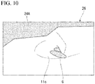
- Fig. 10 is a view showing an example of an image captured by the image sensor 20 including a masking-printed camera cover 24.
- Fig. 10 is an image 26 captured by the image sensor 20, which is partially masked by the masking printing 24A. In this manner, it is possible to physically mask the region included in a part of the image and not intended to be imaged on the image.
- an LED is used for the illuminator 23.
- the illuminator 23 is arranged on the back surface 12a of the toilet seat 12 and in front of the image sensor 20.
- a range of the illumination L illuminated by the illuminator 23 is diffused from the light source such that the illumination center is located at the pooled water portion 11c of the toilet bowl 11.
- the illuminator 23 is arranged so as to substantially coincide with the position where the view field center 20C (see Fig. 5 ) of the image sensor 20 intersects the pooled water portion 11c as a target object.
- the positional relationship between the illuminator 23 and the image sensor 20 shown in the present embodiment is only an example.
- the illuminator 23 only has to be arranged near the image sensor 20 and at a position where the image sensor 20 can illuminate the deep side of the toilet drainage channel opening 14a.
- a plurality of protective legs 5 are provided on the back surface 12a of the toilet seat 12.
- the plurality of protective legs 5 are arranged in the vicinity of the image sensor 20.
- the plurality of protective legs 5 abut on the upper surface 11b of the toilet bowl 11 when the toilet seat 12 is in the closed state.
- the protective leg 5 is an example of a supporter.
- Fig. 4 shows an example having three protective legs 5.
- the protective leg 5 is made of, for example, a rubber member.
- the protective leg 5 projects downward from the back surface 12a of the toilet seat 12 when the toilet seat 12 is closed, and a protruding end 5a of the protective leg 5 abuts on the upper surface 11b of the toilet bowl 11.
- the three protective legs 5 are arranged on the outer peripheral side with respect to the image sensor 20 located on the inner peripheral side of the toilet seat 12, and are arranged at intervals in the circumferential direction.
- the protective leg 5 projects at a height such that the image sensor 20 arranged on the back surface 12a of the toilet seat 12 does not come into contact with the upper surface 11b of the toilet bowl 11 when the toilet seat 12 is in the closed state.
- the protruding length of the protective leg 5 is longer than the length of the image sensor 20 protruding from the back surface 12a of the toilet seat 12.
- the protective leg 5 is provided to be projects such that the image sensor storage portion does not abut on the upper surface 11b of the toilet bowl 11.
- the protective leg 5 may not be provided and the supporter 13 may be provided such that a clearance with the upper surface 11b of the toilet bowl 11 formed by the supporter 13 of the toilet seat 12 is secured to be equal to or larger than the height at which the image sensor storage portion projects from the back surface 12a of the toilet seat 12.
- the protective leg 5 or the supporter 13 of the toilet seat 12 disposed in the vicinity of the image sensor 20 it is possible to prevent any external contact from being applied to the image sensor 20 even in the closed state by the protective leg 5 or the supporter 13 of the toilet seat 12 disposed in the vicinity of the image sensor 20.
- the protective leg 5 or the supporter 13 it is possible to prevent the contact of the image sensor 20 with respect to the upper surface 11b of the toilet bowl 11 due to the deformation of the toilet seat 12.
- the effects of the toilet seat device 1 according to the present embodiment will be described in details based on the figures.
- the imaging control unit determines that it is possible to image according to the open-close information of the toilet seat 12 acquired by the inclination sensor 21, it is possible for the image sensor 20 to image the internal space of the toilet bowl 11. That is, when the imaging control unit 22 determines that it is impossible to image, the imaging by the image sensor 20 is physically stopped.
- the toilet seat device 1 in the state in which the image is impossible at the time of the opening and closing of the toilet seat 12, it is possible to definitely prevent the human body from being unintentionally captured by the image sensor 20 provided on the back surface 12a of the toilet seat 12. Accordingly, in the toilet seat device 1 according to the present embodiment, the user can use at ease by capturing the target image in consideration of the privacy of the user.
- the imaging control unit 22 controls the image sensor 20 to capture the image of the internal space of the toilet bowl 11 when it is determined that the toilet seat 12 is in the closed state based on the open-close information acquired by the inclination sensor 21.
- the imaging control unit 22 may set whether or not to perform the imaging by the image sensor 20 according to the open-close angle of the inclination sensor 21. Therefore, for example, the imaging control unit 22 may perform the control such that the toilet seat 12 is not determined to be in the open state even if the toilet seat 12 is slightly opened or displaced within a range in which the human body is not photobombed in the captured image.
- the image sensor 20 is disposed on the back surface 12a of the toilet seat 12 and may image the internal direction of the toilet drainage channel 14 for discharging the stool G from the pooled water portion 11c of the toilet bowl 11, and the image sensor 20 is arranged to face the direction toward the toilet drainage channel opening 14a.
- the stool G that has rolled into the deep side of the toilet drainage channel opening 14a in the toilet bowl 11 does not become a blind spot for imaging, and the entire excreted stool G can be definitely imaged.
- the image sensor 20 may image the stool G more clearly.
- the image sensor 20 is arranged at a position where the human body is not photobombed in the view field 20A of the image sensor 20. In this case, as described above, it is possible to prevent the human body from being photobombed in the view field 20A imaged by the image sensor 20 when the imaging control unit 22 determines that the imaging may be performed.
- the image sensor 20 is configured such that the image can be adjusted to the brightness according to the illuminance inside the toilet bowl 11, it is possible to image the stool G more clearly by the image sensor 20.
- the camera cover 24 is arranged between the image sensor 20 and the toilet bowl 11, and there is a configuration that the masking printing 24A is printed on the camera cover 24 in the region where the human body is photobombed in the range of the view angle (view field 20A) of the image sensor 20.
- the region of the masking printing 24A can be easily changed according to the position of the image sensor 20 and the shape of the toilet 10.
- the toilet seat device 1 has a function of detecting a dirt on the camera lens 20a of the image sensor 20 from the image captured by the image sensor 20 and outputting a cleaning-requirement signal.
- the cleaning-requirement signal is a signal meaning that the camera lens 20a needs to be cleaned. Based on the cleaning-requirement signal, a sign for requiring cleaning is displayed on a display that is not shown in the figures. In this case, the camera lens 20a may be cleaned when the user recognizes the sign that cleaning is required. Therefore, it is possible to always acquire the image easy to see, and it is possible to prevent a problem that it becomes difficult to determine the stool G being captured in image due to the dirt on the camera lens 20a of the image sensor 20.
- the protective legs 5 are provided on the back surface 12a of the toilet seat 12 so as to come into contact with the upper surface 11b of the toilet bowl 11 when the toilet seat 12 is in the closed state. Even if the toilet seat 12 bends due to the weight of the user when the user sits on the toilet seat, the protective legs 5 support the toilet seat 12 so as to prevent the position of the toilet seat 12 from being significantly displaced. As a result, it is possible to prevent the imaging range of the image sensor 20 from being shifted and to prevent the image sensor 20 from being damaged due to stress from the toilet seat 12.
- the toilet seat device 1 captures the target image in consideration of the privacy of the user, such that the user can use it at ease.
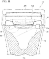
- Fig. 11 shows a vertical cross section of the toilet seat device 1A according to the second embodiment as viewed from the front.
- the toilet seat device 1A according to the second embodiment has a configuration in which the image sensor 20 is arranged at a position separated from the back surface 12a of the toilet seat 12 toward the toilet bowl 11 (downward).
- the image sensor 20 may have a configuration in which the image sensor 20 is attached to a spacer (not shown) that functions as a sensor fixer having an arbitrary shape provided on the back surface 12a of the toilet seat 12.
- the sensor fixing portion is an example of a photobomb preventer.
- the image sensor 20 may be provided integrally with the toilet seat 12 in a shape protruding downward from the lower surface of the toilet seat 12.
- the image sensor 20 since the image sensor 20 is provided to project downward at the inside of the toilet bowl 11, even in a case in which the buttock M of the human body sitting on the toilet seat 12 is located below the back surface 12a of the toilet seat 12, the image sensor 20 may be positioned below the lower surface Ma of the buttock M. Therefore, it is possible to realize a configuration in which the human body is not physically in the view field of the image sensor 20. In the second embodiment, it is possible to prevent the human body from being photobombed in the image captured by the image sensor 20, and by capturing the target image in consideration of the privacy of the user, the user can use it at ease.
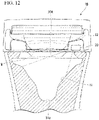
- Fig. 12 is a view showing a vertical cross section of a toilet seat device 1B according to a third embodiment as viewed from the front.
- the toilet seat device 1B according to the third embodiment has a portion for increasing the thickness of the toilet seat 12, and a size thereof is set such that the buttocks M of the person sitting on the seat does not fall below the back surface 12a of the toilet seat 12.
- the portion for increasing the thickness of the toilet seat 12 is an example of the photobomb preventer.
- the position of the image sensor 20 in this case is the same as that of the first embodiment described above, and the image sensor 20 is directly provided on the back surface 12a of the toilet seat 12.
- the toilet seat 12 since the thickness of the toilet seat 12 itself is increased, the toilet seat 12 has a structure that may physically prevent the buttocks M of the human body sitting on the toilet seat 12 from being located below the back surface 12a of the toilet seat 12. In the third embodiment, it is possible to prevent the human body from being photobombed in the image captured by the image sensor 20, and the user can use at ease since the target image is captured in consideration of the privacy of the user.
- Fig. 13 shows a vertical cross section of a toilet seat device 1C according to a fourth embodiment as viewed from the front.
- the toilet seat device 1C according to the fourth embodiment has an opening reduction portion in which a radial dimension of the opening 12b of the toilet seat 12, particularly the length in the left-right direction X2, is reduced, and has a configuration with a shape set such that the buttock portion M of the person sitting on the seat does not fall below the back surface 12a of the toilet seat 12.
- the opening reduction portion is an example of the photobomb preventer.
- the position of the image sensor 20 in this case is the same as that of the first embodiment described above, and is directly provided on the back surface 12a of the toilet seat 12.
- the toilet seat 12 since the opening 12b of the toilet seat 12 becomes smaller, the toilet seat 12 has a structure for physically preventing the buttocks M of the human body sitting on the toilet seat 12 from being located below the back surface 12a of the toilet seat 12.
- the toilet seat 12 it is possible to prevent the human body from being photobombed in the image captured by the image sensor 20, and the user can use at ease since the target image is captured in consideration of the privacy of the user.
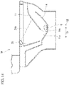
- Fig. 14 shows a cross section of a toilet seat device 1D according to a fifth embodiment at the center in the left-right direction and along the front-rear direction.
- the inclination sensor 21 accommodated in the toilet seat 12 is adopted as the open-close acquiring unit for detecting the open-close of the toilet seat 12, and the open-close information is obtained by the inclination angle of the toilet seat 12.
- the configuration of the open-close acquiring unit is not limited to this example.
- the fifth embodiment is an example in which the open-close acquiring unit is adopted as shown in Fig. 14 .
- a sitting sensor (not shown) for detecting when the user is sitting on the toilet seat 12 is provided, and the sitting sensor may be configured to control the image sensor 20 to image the internal space of the toilet bowl 11 only when it is determined that the user is sitting on the seat.
- the sitting sensor may adopt a load sensor or the like.
- Fig. 15 shows a vertical cross section of a toilet seat device 1D according to a sixth embodiment as viewed from the front.
- the toilet seat device 1D according to the sixth embodiment has a configuration in which the image sensor 20 is separately provided below the toilet seat 12.
- a region where the image sensor 20 is provided that is, the region separated from the toilet seat 12 and below the toilet seat 12 is included in the back surface of the toilet seat 12. That is, the back surface of the toilet seat 12 also includes the lower region of the toilet seat 12.
- the toilet seat device 1D is provided with a connecting bar 3 formed of, for example, a metal member.
- the connecting bar 3 is provided on the upper surface 10a of the toilet 10 to bridge between the inside of the toilet and the outside of the toilet.
- the image sensor 20 is attached to a lower surface 3c of an inner-toilet end portion 3a of the connecting bar 3 so as to image the internal space of the toilet 10.
- An outer-toilet end portion 3b of the connecting bar 3 is attached to an outer peripheral surface of the toilet 10 by sticking or suctioning.
- the image sensor 20 is located below the toilet seat 12 and on the lateral side of the rim 10A of the toilet 10. Specifically, the image sensor 20 is arranged on the lateral side of the rim 10A from a position at the same height as the upper surface 10a of the toilet bowl to the lateral side of an upper rim 10c and a standing surface 10d of the rim 10A.
- the image sensor 20 may be a sensor including the image sensor 20.
- a band-shaped member extending in one direction is bent in an L shape from a toilet upper surface 10a along the outer shape of the outer peripheral surface.
- the inner-toilet end portion 3a of the connecting bar 3 projects from the toilet upper surface 10a toward the inside of the toilet 10.
- the outer-toilet end portion 3b is fixed to the toilet 10 with an adhesive.
- the means for fixing the connecting bar 3 to the toilet 10 may be a suction cup instead of an adhesive. In the case of using the suction cup, it is easy to attach to and detach from the toilet 10 such that an effect of making cleaning and maintenance to be easy may be realized, and further, the position of the image sensor 20 may be easily adjusted.
- Fig. 16 shows a vertical cross section of a part of a toilet seat device of the first modification example of the sixth embodiment as viewed from the front.
- a weight 31 for maintaining a load balance with the image sensor 20 provided at the inner-toilet end portion 3a is attached to the outer-toilet end portion 3b of the connecting bar 3.
- the weight 31 is fixed on a surface facing the outside of the outer-toilet end portion 3b opposite to the toilet 10 side, for example, with an adhesive or the like.
- the weight 31 may be, for example, a metal member.
- the weight 31 may be, for example, a camera functional part that functions as an image processor or the like that processes data of the image sensor 20.
- the image sensor 20 is attached to the toilet 10 in a state in which the image sensor 20 is positioned in a balanced manner by the weight of the weight 31 of the connecting bar 3, and it is possible to prevent the image sensor 20 from inclining or shifting.
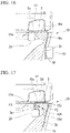
- Fig. 17 shows a vertical cross section of a part of a toilet seat device of a second modification example of the sixth embodiment as viewed from the front.
- the connecting bar 3 of the second modification example is formed of a metal wire, a metal plate or the like.
- the connecting bar 3 is bent into a substantially U shape.
- the connecting bar 3 has a central portion 3d in the length direction that is disposed on the toilet upper surface 10a and has a configuration in which an elastic force is generated in a direction (the arrow F1 and arrow F2 shown in Fig. 17 ) in which the inner-toilet end portion 3a and the outer-toilet end portion 3b being opposite to each other approach each other.
- the image sensor 20 is attached to the inner-toilet end portion 3a.
- the connecting bar 3 is attached thereto to sandwich the upper portion of the toilet 10 such that the inner-toilet end portion 3a and the outer-toilet end portion 3b are fitted onto the upper portion of the toilet 10 from the outside in a state in which the inner-toilet end portion 3a and the outer-toilet end portion 3b are in an open state against the force along the direction (the arrow F1 and arrow F2 shown in Fig. 17 ) in which the inner-toilet end portion 3a and the outer-toilet end portion 3b being opposite to each other approach each other.
- the image sensor 20 is attached to the toilet 10 in the state in which the image sensor 20 is positioned in the balanced manner due to the weight of the weight 31 of the connecting bar 3, and it is possible to prevent the image sensor 20 from inclining and shifting.
- the image sensor 20 is arranged on the lateral side of the rim 10A below the back surface 12a of the toilet seat 12. Specifically, the image sensor 20 is arranged on the lateral side of the rim 10A at a position at a height below the upper rim 10c and on the lateral side of the standing surface 10d of the rim 10A.
- the region may include the region below the toilet seat 12.
- Fig. 18 shows a vertical cross section of a toilet seat device 1E according to a seventh embodiment as viewed from the front.
- the toilet seat device 1E according to the seventh embodiment has a configuration in which the image sensor 20 is directly fixed to the back surface 12a of the toilet seat 12 via a fixing portion 32 such as an adhesive or the like.
- An attachment position of the image sensor 20 with respect to the toilet seat 12 is a position closer to an inner circumference of the toilet seat 12, and the image sensor 20 attached when the toilet seat 12 is in the closed state (the state shown in Fig. 18 ) is disposed at a position not to interfere with the upper portion of the toilet 10.
- the structure is only configured to fix the image sensor 20 to the toilet seat 12. Accordingly, the toilet seat device 1E does not require a separate member such as the connecting bar 3 (see Fig. 15 ) of the sixth embodiment described above, and there is an advantage that the image sensor 20 may be easily attached to reduce the member cost.
- Fig. 19 shows a vertical cross section of a part of a toilet seat device 1F according to an eighth embodiment as viewed from the front.
- the toilet seat device 1F according to the eighth embodiment is an example in which the image sensor 20 is attached to the toilet seat 12 via a second connecting bar 3A.
- the second connecting bar 3A is formed of, for example, a metal wire or a metal plate.
- the second connecting bar 3A extends between the back surface 12a of the toilet seat 12 and the outside of the toilet seat 12.
- the image sensor 20 is attached to the lower surface 3c of the inner-toilet end portion 3a of the second connecting bar 3A so as to image the internal space of the toilet 10.
- the outer-toilet end portion 3b of the second connecting bar 3A projects outward of the toilet seat 12.
- a camera functional part 26 that is electrically connected to the image sensor 20 is provided in the outer-toilet end portion 30b.
- the camera functional part 26 is arranged along the outer side surface 12c of the toilet seat 12.
- the central portion 3d of the second connecting bar 3A is fixed to the back surface 12a of the toilet seat 12 by a fixing means such as an adhesive, a suction cup or the like.
- the camera functional part 26 has a function such as an image processer configured to process the data of the image sensor 20.
- the image sensor 20 may be retrofitted to the toilet seat 12 side via the second connecting bar 3A. Therefore, a simpler structure than the case of attaching the image sensor 20 to the toilet 10 may be adopted.
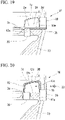
- Fig. 20 shows a vertical cross section of a part of a toilet seat device 1G according to a ninth embodiment as viewed from the front.
- the toilet seat device 1G according to the ninth embodiment is an example in which the image sensor 20 is attached to the toilet seat 12 via a third connecting bar 3B.
- the third connecting bar 3B is formed of, for example, a metal wire or a metal plate.
- the third connecting bar 3B is bent into a substantially U shape to bridge the upper side of the toilet seat 12.
- the connecting bar 3 has a central portion 3d in the length direction disposed on the toilet seat 12.
- the image sensor 20 is attached to the inner-toilet end portion 3a of the third connecting bar 3A so as to image the internal space of the toilet 10.
- the image sensor 20 attached to the third connecting bar 3A is provided to be located on the back surface 12a of the toilet seat 12.
- the camera functional part 26 is provided on the outer-toilet end portion 3b of the third connecting bar 3A along the outer surface 12c of the toilet seat 12.
- the camera functional part 26 is electrically connected to the image sensor 20.
- the third connecting bar 3B is fixed by pressing the outer-toilet end portion 3b against the outer side surface 12c of the toilet seat 12 by a pressing member 33 such as a screw or the like pressing from the outside of the outer-toilet end portion 3b.
- the method of fixing the third connecting bar 3 to the toilet seat 12 is not limited to the pressing member 33 described above, and other fixing method may be adopted.
- the central portion 3d of the third connecting bar 3B may be fixed to the upper surface 12d of the toilet seat 12 by a fixing means such as an adhesive, a suction cup or the like.
- the third connecting bar 3B may be attached to the toilet seat 12 by sandwiching the toilet seat 12 from two sides such that an elastic force is generated in the direction in which the inner-toilet end portion 3a and the outer-toilet end portion 3b facing each other approach each other.
- Fig. 21 and Fig. 22 show a vertical cross section of a part of a toilet seat device 1H according to a tenth embodiment as viewed from the front.
- the toilet seat device 1H and a toilet seat device 1I according to the tenth embodiment have a structure in which separate toilet seat 4A and toilet seat 4B are sandwiched between the toilet seat 12 and the toilet upper surface 10a.
- the image sensor 20 is fixed to a lower surface 41a of a toilet-seat-type insertion member 41.
- the image sensor 20 is built in the toilet-seat-type insertion member 41.
- the toilet-seat-type insertion member 41 is formed to have substantially the same shape as the toilet seat 12 in a plan view, and is provided to open and close with respect to the upper surface 10a together with the toilet seat 12 or individually from the toilet seat 12. In a state in which the toilet-seat-type insertion member 41 is in the closed state, the lower surface 41a of the toilet-seat-type insertion member 41 is disposed on the toilet upper surface 10a, and the upper surface 41b of the toilet-seat-type insertion member 41 is in contact with the back surface 12a of the toilet seat 12.
- the image sensor 20 is attached so as to image the internal space of the toilet 10.
- an image processor configured to perform image processing on the target image acquired by the image sensor 20 may be provided in the image determination device 2.
- the process of masking, hiding, or erasing the region in which the human body is photobombed in the target image may be performed.
- the toilet seat device 1 in which the toilet drainage channel 14 for draining water from the pooled water portion 11c of the toilet bowl 11 toward the rear side of the toilet 10 and the image sensor 20 is arranged in front of the toilet seat 12 is shown.
- the toilet seat device is not limited to such a toilet structure, and may be a toilet seat device having another structure.
- the toilet seat device 1D according to the fifth embodiment shown in Fig. 14 the configuration in which the toilet drainage channel 14 for draining water from the pooled water portion 11c toward the front side of the toilet 10 is provided, and the image sensor 20 is arranged at the rear side of the toilet may be realized.
- the configuration in which the protective legs 5 are provided on the back surface 12a of the toilet seat 12 as supporters to be in contact with the upper surface 11b of the toilet bowl 11 when the toilet seat 12 is in the closed state is disclosed as example.
- the toilet seat is not limited to the configuration in which the protective legs 5 are provided, and the protective legs 5 may be omitted.
- the supporter is not limited to the configuration such as the shape and amount of the protective legs 5 according to the above-described embodiment, and can be appropriately set.
- the user can use the toilet seat device at ease by capturing the target image in consideration of the privacy of the user.
Landscapes
- Health & Medical Sciences (AREA)
- Life Sciences & Earth Sciences (AREA)
- Public Health (AREA)
- Medical Informatics (AREA)
- Surgery (AREA)
- Engineering & Computer Science (AREA)
- Biomedical Technology (AREA)
- Heart & Thoracic Surgery (AREA)
- Veterinary Medicine (AREA)
- Molecular Biology (AREA)
- Pathology (AREA)
- Animal Behavior & Ethology (AREA)
- General Health & Medical Sciences (AREA)
- Biophysics (AREA)
- Physics & Mathematics (AREA)
- Physiology (AREA)
- Urology & Nephrology (AREA)
- Toilet Supplies (AREA)
- Bidet-Like Cleaning Device And Other Flush Toilet Accessories (AREA)
Abstract
Description
- The present disclosure relates to a toilet seat device. Priority is claimed on
Japanese Patent Application No. 2019-173282, filed September 24, 2019 Japanese Patent Application No. 2020-083273, filed May 11, 2020 - For example, in
Patent Document 1, a toilet bowl in which a camera is arranged on the toilet bowl so as to capture a pooled water portion of the toilet bowl in which excrement is located is disclosed. - [Patent Document 1]
Japanese Unexamined Patent Application, First Publication No. 2007-252805 - In a conventional toilet seat device, measures for preventing a human body from being captured are insufficient. That is, there is a demand for a toilet seat device that physically realizes that the human body is not photobombed in the captured image such that the user can use the toilet seat device at ease, and there is room for improvement in that respect.
- The present disclosure provides a toilet seat device configured to capture a target image in consideration of the privacy of the user such that the user can use at ease.
- A toilet device according to an aspect of the present disclosure includes a toilet seat disposed on an upper side of a toilet; an image sensor provided on a back surface of the toilet seat and configured to image an inner space of a toilet bowl at time of excretion; an open-close acquiring unit configured to acquire open-close information of the toilet seat; and an imaging control unit configured to determine whether or not to image by the image sensor according to the open-close information of the toilet seat acquired by the open-close acquiring unit.
- A toilet device according to another aspect of the present disclosure includes a toilet seat disposed on an upper side of a toilet; an image sensor provided individually from the toilet seat and on a lower side of the toilet seat, the image sensor being configured to image an inner space of a toilet bowl at the time of excretion; an open-close acquiring unit configured to acquire open-close information of the toilet seat; and an imaging control unit configured to determine whether or not to image by the image sensor according to the open-close information of the toilet seat acquired by the open-close acquiring unit.
-
-
Fig. 1 is a perspective view showing a toilet seat device according to a first embodiment of the present disclosure. -
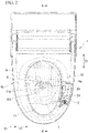
Fig. 2 is a plan view showing the toilet seat device shown inFig. 1 viewed from an upper side. -
Fig. 3 is a cross-sectional view taken along line A-A inFig. 2 . -
Fig. 4 is a view showing a back surface of the toilet seat shown inFig. 1 . -
Fig. 5 is a cross-sectional view taken along line B-B shown inFig. 3 . -
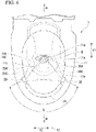
Fig. 6 is a plan view showing a toilet of the toilet seat device viewed from the upper side. -
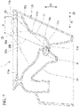
Fig. 7 is a cross-sectional view taken along line C-C shown inFig. 6 . -
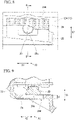
Fig. 8 is a plan view of a camera cover. -
Fig. 9 is a cross-sectional view taken along line D-D shown inFig. 8 . -
Fig. 10 is a view showing an example of an image captured by an image sensor. -
Fig. 11 is a vertical cross-sectional view of a toilet seat device according to a second embodiment. -
Fig. 12 is a vertical cross-sectional view of a toilet seat device according to a third embodiment. -
Fig. 13 is a vertical cross-sectional view of a toilet seat device according to a fourth embodiment. -
Fig. 14 is a vertical cross-sectional view of a toilet seat device according to a fifth embodiment. -
Fig. 15 is a vertical cross-sectional view of a toilet seat device according to a sixth embodiment. -
Fig. 16 is a vertical cross-sectional view of a toilet seat device according to a first modification example. -
Fig. 17 is a vertical cross-sectional view of a toilet seat device according to a second modification example. -
Fig. 18 is a vertical cross-sectional view of a toilet seat device according to a seventh embodiment. -
Fig. 19 is a vertical cross-sectional view showing a part of a toilet seat device according to an eighth embodiment. -
Fig. 20 is a vertical cross-sectional view showing a part of a toilet seat device according to a ninth embodiment. -
Fig. 21 is a vertical cross-sectional view showing a part of a toilet seat device according to a tenth embodiment. -
Fig. 22 is a vertical cross-sectional view showing a part of a toilet seat device according to the tenth embodiment. - Hereinafter, various embodiments of a toilet seat device according to the present disclosure will be described referring to figures.
- As shown in
Fig. 1 andFig. 2 , atoilet seat device 1 according to the first embodiment includes atoilet 10, atoilet seat 12, a toilet lid, and animage determination device 2. Thetoilet 10 has atoilet bowl 11. Thetoilet seat 12 is provided to be openable and closable with respect to thetoilet 10. The toilet lid is provided to be openable and closable with respect to thetoilet seat 12. The toilet lid is not shown in figures. Theimage determination device 2 is configured to acquire an image of a stool G excreted by a user, and determines a state of the stool G or the like based on the acquired image. -
Fig. 1 is a perspective view of thetoilet seat device 1 viewed from diagonally upper side thereof, and is a view in which a part of the toilet seat is broken. InFig. 1 , thetoilet seat 12 in a closed state is shown. The toilet lid in the closed state covers an opening 11a of thetoilet bowl 11 shown inFig. 4 from the upper side with thetoilet seat 12 sandwiched therebetween. - In the following description, a side in front of the user of the
toilet seat device 1 is referred to as a front side in a state in which the user sits on thetoilet seat 12. In the same state, a side behind the user is referred to as called the rear side. A direction connecting the front side and the rear side is referred to as a front-rear direction X1. A left side viewed from the user sitting on thetoilet seat 12 is referred to as a "left side", and a right side is referred to as a "right side". A direction connecting the left side and the right side is referred to as a left-right direction X2. A side away from a floor surface on which thetoilet seat device 1 is disposed is referred to as an "upper side", and a side closer to the floor surface is referred to as a "lower side". A direction connecting the upper side and the lower side is referred to as a vertical direction X3. - As shown in
Fig. 3 , a rim is provided on anupper surface 11b of the opening 11a of thetoilet bowl 11. The rim projects toward an inner space of thetoilet bowl 11. A pooledwater portion 11c is arranged at a bottom portion of thetoilet bowl 11. The pooledwater portion 11c is connected to atoilet drainage channel 14 for discharging the stool G from thetoilet bowl 11. - A rotation shaft O1 extending in the left-right direction X2 is provided at the rear portion of the
toilet 10. Thetoilet seat 12 is configured to be freely rotatable around therotation shaft 01. Thetoilet seat 12 is possible to enter either of a closed state or an open state by rotating as described above. In the closed state, thetoilet seat 12 is in contact with an upper end portion of thetoilet bowl 11 and extends in both the left-right direction X2 and the front-back direction X1. In the open state, thetoilet seat 12 is away from theupper surface 11b of thetoilet bowl 11 and extends at least in the vertical direction X3. Thetoilet seat 12 has an annular shape that extends continuously in a circumferential direction. Thetoilet seat 12 is in contact with theupper surface 11b of thetoilet bowl 11 in the closed state. An opening size of theopening 12b of thetoilet seat 12 is set to be slightly smaller than am opening size of theopening 11a of thetoilet bowl 11 when viewed from the upper side. When thetoilet seat 12 is in the closed state, thetoilet seat 12 projects laterally from theupper surface 11b of thetoilet bowl 11 toward an inner space. -
Fig. 4 is a view showing a back surface of thetoilet seat 12 when thetoilet seat 12 is in the open state. As shown inFig. 4 andFig. 5 , theback surface 12a of thetoilet seat 12 is provided withsupport members 13 projecting downward at four locations in the circumferential direction. The foursupport members 13 are configured to support thetoilet seat 12 at four points with respect to theupper surface 11b of thetoilet bowl 11 when thetoilet seat 12 is in the closed state. - The toilet lid that is not shown in figures is configured to be freely rotatable around a rotation axis extending in the left-right direction X2. The toilet lid can enter either the closed state or the open state. In the closed state, the toilet lid covers the
toilet seat 12 in the closed state and extends in the left-right direction X2 and the front-back direction X1 while closing the opening of each of thetoilet bowl 11 and thetoilet seat 12. In the open state, the toilet lid extends at least in the vertical direction X3. The toilet lid is provided so as to open and close the opening of thetoilet bowl 11 and the opening of thetoilet seat 12. - An
image determination device 2 is provided on theback surface 12a of thetoilet seat 12. Theimage determination device 2 includes animage sensor 20, aninclination sensor 21, animaging control unit 22, and anilluminator 23. Theimage sensor 20 is provided on theback surface 12a of thetoilet seat 12. Theinclination sensor 21 acquires open-close information of thetoilet seat 12. Theinclination sensor 21 is an example of an open-close acquiring unit. Theimaging control unit 22 controls the propriety of imaging by theimage sensor 20 according to the open-close information of thetoilet seat 12 acquired by theinclination sensor 21. Theilluminator 23 emits light toward a deep side of thetoilet drainage channel 14 such that the stool G that has moved from the bottom surface of the pooledwater portion 11c of thetoilet 10 toward the deep side, which is the downstream side of thetoilet drainage channel 14, can be imaged. - The
inclination sensor 21 is accommodated in thetoilet seat 12. Theinclination sensor 21 is set to detect that thetoilet seat 12 has begun to open when thetoilet seat 12 is opened by a certain angle or more. As an example, theinclination sensor 21 can employ a sensor in which a ball is accommodated inside such that the inclination of thetoilet seat 12 is detected by the movement of the ball. Theinclination sensor 21 is set to not to detect the inclination of thetoilet seat 12 when thetoilet seat 12 slightly rattles and lifts. Theinclination sensor 21 is set to react when thetoilet seat 12 is opened equal to or more than a predetermined angle. The open-close acquiring unit may use an automatic open-close device of thetoilet seat 12 as the open-close sensor besides theinclination sensor 21. - In the present embodiment, the
imaging control unit 22 is arranged on thetoilet 10. Theimaging control unit 22 is provided to be able to communicate wirelessly or by wire with theimage sensor 20 and theinclination sensor 21. When theimage sensor 22 determines that thetoilet seat 12 is in the open state based on the open-close information acquired by theinclination sensor 21, theimage sensor 20 includes the control of stopping theimage sensor 20 from capturing the image of the internal space (pooledwater portion 11c) of thetoilet bowl 11 and the control capable of deleting the image captured when it is determined that thetoilet seat 12 is in the open state. Theimaging control unit 22 may be configured to interlock with a sitting sensor such as a load sensor or the like for detecting that the user is sitting on thetoilet seat 12 and control the imaging of the internal space of thetoilet bowl 11 by theimage sensor 20 when the sitting is detected. The sitting sensor is not shown in the figures. - The
image sensor 20 has a camera lens and an imaging device. Theimage sensor 20 is disposed on theback surface 12a of thetoilet seat 12 and is arranged to face the toiletdrainage channel opening 14a of thetoilet drainage channel 14. Theimage sensor 20 is arranged such that an internal direction of thetoilet drainage channel 14 to which the stool G is discharged from the pooledwater portion 11c of thetoilet bowl 11 can be imaged by the imaging device. -
Fig. 6 is a plan view of thetoilet 10 of thetoilet seat device 1 as viewed from above. InFig. 6 , the toilet seat is not shown. As shown inFig. 6 andFig. 7 , theimage sensor 20 is arranged in front of the pooledwater portion 11c. Theimage sensor 20 is arranged at a position where the deep side (rear side) of the toiletdrainage channel opening 14a as an entrance of thetoilet drainage channel 14 can be captured. A sensor arrangement region R of theimage sensor 20 of thetoilet seat device 1 is a range from the front region of the toilet seat to the lateral region of the toilet seat between the left side and the right side thereof, and is a left-right symmetrical region sandwiching the center of the left-right direction X2. The front region of the toilet seat is a region in which the stool G that has entered the toiletdrainage channel opening 14a of thetoilet bowl 11 can be easily seen. The lateral region of the toilet seat is a region where theopening 14a of the toilet drainage channel of thetoilet bowl 11 can be peeped into, and it is possible to avoid the human body from being photobombed in a view angle (view field 20A) of theimage sensor 20 in consideration of the psychological point of the user. The photobombing of the human body in the image means that in addition to the human body, an unintended object such as the buttocks, thighs, and male genitalia of the human body are captured in the image captured by theimage sensor 20. In the photobombing of the human body in the image, in addition to a case in which the human body is directly imaged and captured, a case in which a state where the human body is reflected and imaged on the water surface Wa of the pooledwater portion 11c is captured and the human body is imaged on the water surface Wa of the pooledwater portion 11c in the captured image. - The
image sensor 20 is arranged such that a line connecting the center of the camera lens and thelower end surface 11d of the opening of the toiletdrainage channel opening 14a is aview field center 20C of theimage sensor 20. At this time, it is preferable that theview field center 20C of theimage sensor 20 is not shielded by the inner surface of thetoilet bowl 11. For example, as shown inFig. 7 , theimage sensor 20 located in front of thetoilet seat 12 is arranged such that theview field center 20C does not intersect a convexcurved surface 11e formed on the front inner surface of thetoilet bowl 11. Here, thelower end surface 11d of the opening of the toiletdrainage channel opening 14a is a predetermined region extending in the left-right direction X2 indicated by thereference sign 11A in the front view shown inFig. 5 . - As shown in
Fig. 5 , theimage sensor 20 is preferably arranged such that thefield view center 20C (20Ca, 20Cb) of theimage sensor 20 faces toward the opposite position with respect of the image sensor by sandwiching the center line C of the pooledwater portion 11c in the left-right direction X2 in the front view. Regarding theimage sensor 20, the risk of the human body being reflected and imaged on the water surface Wa inside thetoilet bowl 11 is reduced in a case of arranging the view field center along the arrow indicated by the reference sign 20Cb shown inFig. 5 than a case of arranging the view field center along the arrow indicated by the reference sign 20Ca shown inFig. 5 . Theimage sensor 20 only has to be arranged in the direction of viewing the pooledwater portion 11c from the position of theimage sensor 20, and theview field center 20C of theimage sensor 20 is directed to the distal side from the position of half of the water surface of the pooledwater portion 11c in thetoilet bowl 11. - The
image sensor 20 has other functions besides the above-described functions. For example, it has a function of adjusting the brightness of the image according to the illuminance inside thetoilet bowl 11. - The
imaging control unit 22 may have a function of detecting dirt on the camera lens of theimage sensor 20 from the image and prompting the user to clean the camera lens from the detected detection information. -
Fig. 8 is a plan view of a masking-printedcamera cover 24 as viewed from the lower side. As shown inFig. 8 and Fig. 9 , atransparent camera cover 24 is provided in theimage sensor 20. Thecamera cover 24 is arranged at a position at a predetermined distance d (seeFig. 9 ) from the camera lens in the imaging direction. Thecamera cover 24 physically masks a part of the human body, for example, a part in which the buttocks, thighs, male genitalia or the like are imaged, that is, a part of maskingprinting 24A described later. Thecamera cover 24 is arranged within a range of the view angle of theimage sensor 20 between theimage sensor 20 and thetoilet bowl 11. Thecamera cover 24 is attached to thetoilet seat 12a via ajig 25 fixed to theback surface 12a of thetoilet seat 12. Thecamera cover 24 is printed or painted with anopaque masking print 24A in a predetermined region of the image in which a part of the human body is photobombed. The maskingprint 24A is an example of a shield. -
Fig. 10 is a view showing an example of an image captured by theimage sensor 20 including a masking-printedcamera cover 24.Fig. 10 is animage 26 captured by theimage sensor 20, which is partially masked by the maskingprinting 24A. In this manner, it is possible to physically mask the region included in a part of the image and not intended to be imaged on the image. - As shown in
Fig. 4 , for example, an LED is used for theilluminator 23. Theilluminator 23 is arranged on theback surface 12a of thetoilet seat 12 and in front of theimage sensor 20. As shown inFig. 1 ,Fig. 2 ,Fig. 3 , andFig. 5 , a range of the illumination L illuminated by theilluminator 23 is diffused from the light source such that the illumination center is located at the pooledwater portion 11c of thetoilet bowl 11. Theilluminator 23 is arranged so as to substantially coincide with the position where theview field center 20C (seeFig. 5 ) of theimage sensor 20 intersects the pooledwater portion 11c as a target object. The positional relationship between the illuminator 23 and theimage sensor 20 shown in the present embodiment is only an example. Theilluminator 23 only has to be arranged near theimage sensor 20 and at a position where theimage sensor 20 can illuminate the deep side of the toiletdrainage channel opening 14a. - As shown in
Fig. 4 , a plurality ofprotective legs 5 are provided on theback surface 12a of thetoilet seat 12. The plurality ofprotective legs 5 are arranged in the vicinity of theimage sensor 20. The plurality ofprotective legs 5 abut on theupper surface 11b of thetoilet bowl 11 when thetoilet seat 12 is in the closed state. Theprotective leg 5 is an example of a supporter.Fig. 4 shows an example having threeprotective legs 5. Theprotective leg 5 is made of, for example, a rubber member. As shown inFig. 3 andFig. 5 , theprotective leg 5 projects downward from theback surface 12a of thetoilet seat 12 when thetoilet seat 12 is closed, and aprotruding end 5a of theprotective leg 5 abuts on theupper surface 11b of thetoilet bowl 11. When thetoilet seat 12 is in the closed state, thetoilet seat 12 is supported by thelower toilet bowl 11 by the foursupport members 13 and the threeprotective legs 5. The threeprotective legs 5 are arranged on the outer peripheral side with respect to theimage sensor 20 located on the inner peripheral side of thetoilet seat 12, and are arranged at intervals in the circumferential direction. - The
protective leg 5 projects at a height such that theimage sensor 20 arranged on theback surface 12a of thetoilet seat 12 does not come into contact with theupper surface 11b of thetoilet bowl 11 when thetoilet seat 12 is in the closed state. For example, the protruding length of theprotective leg 5 is longer than the length of theimage sensor 20 protruding from theback surface 12a of thetoilet seat 12. For example, in a case in which there is a portion in the image sensor storage portion protruding from theback surface 12a of thetoilet seat 12, theprotective leg 5 is provided to be projects such that the image sensor storage portion does not abut on theupper surface 11b of thetoilet bowl 11. Alternatively, theprotective leg 5 may not be provided and thesupporter 13 may be provided such that a clearance with theupper surface 11b of thetoilet bowl 11 formed by thesupporter 13 of thetoilet seat 12 is secured to be equal to or larger than the height at which the image sensor storage portion projects from theback surface 12a of thetoilet seat 12. - Accordingly, it is possible to prevent any external contact from being applied to the
image sensor 20 even in the closed state by theprotective leg 5 or thesupporter 13 of thetoilet seat 12 disposed in the vicinity of theimage sensor 20. For example, when thetoilet seat 12 is in the closed state, there is a case in which thetoilet seat 12 is deformed due to the load of the user sitting thereon. Even in such a situation, by theprotective leg 5 or thesupporter 13, it is possible to prevent the contact of theimage sensor 20 with respect to theupper surface 11b of thetoilet bowl 11 due to the deformation of thetoilet seat 12. - Next, the effects of the
toilet seat device 1 according to the present embodiment will be described in details based on the figures. As shown inFig. 3 andFig. 4 , in thetoilet seat device 1 according to the present embodiment, only when the imaging control unit determines that it is possible to image according to the open-close information of thetoilet seat 12 acquired by theinclination sensor 21, it is possible for theimage sensor 20 to image the internal space of thetoilet bowl 11. That is, when theimaging control unit 22 determines that it is impossible to image, the imaging by theimage sensor 20 is physically stopped. Accordingly, for example, in the state in which the image is impossible at the time of the opening and closing of thetoilet seat 12, it is possible to definitely prevent the human body from being unintentionally captured by theimage sensor 20 provided on theback surface 12a of thetoilet seat 12. Accordingly, in thetoilet seat device 1 according to the present embodiment, the user can use at ease by capturing the target image in consideration of the privacy of the user. - In the present embodiment, the
imaging control unit 22 controls theimage sensor 20 to capture the image of the internal space of thetoilet bowl 11 when it is determined that thetoilet seat 12 is in the closed state based on the open-close information acquired by theinclination sensor 21. In this case, for example, when thetoilet seat 12 is opened at a predetermined angle or more, the imaging by theimage sensor 20 is stopped such that the imaging is controlled to be performed only when the user sits on thetoilet seat 12 and excretes. Therefore, the imaging is not performed before and after the user sitting on the toilet seat, and the user can use thetoilet seat device 1 at ease. Theimaging control unit 22 may set whether or not to perform the imaging by theimage sensor 20 according to the open-close angle of theinclination sensor 21. Therefore, for example, theimaging control unit 22 may perform the control such that thetoilet seat 12 is not determined to be in the open state even if thetoilet seat 12 is slightly opened or displaced within a range in which the human body is not photobombed in the captured image. - In the present embodiment, the
image sensor 20 is disposed on theback surface 12a of thetoilet seat 12 and may image the internal direction of thetoilet drainage channel 14 for discharging the stool G from the pooledwater portion 11c of thetoilet bowl 11, and theimage sensor 20 is arranged to face the direction toward the toiletdrainage channel opening 14a. In this case, the stool G that has rolled into the deep side of the toiletdrainage channel opening 14a in thetoilet bowl 11 does not become a blind spot for imaging, and the entire excreted stool G can be definitely imaged. - In the present embodiment, since the
illuminator 23 can irradiate the deep side of thetoilet bowl 11 from the bottom surface of the pooledwater portion 11c of thetoilet drainage channel 14, theimage sensor 20 may image the stool G more clearly. - In the present embodiment, the
image sensor 20 is arranged at a position where the human body is not photobombed in theview field 20A of theimage sensor 20. In this case, as described above, it is possible to prevent the human body from being photobombed in theview field 20A imaged by theimage sensor 20 when theimaging control unit 22 determines that the imaging may be performed. - In the present embodiment, since the
image sensor 20 is configured such that the image can be adjusted to the brightness according to the illuminance inside thetoilet bowl 11, it is possible to image the stool G more clearly by theimage sensor 20. - In the present embodiment, the
camera cover 24 is arranged between theimage sensor 20 and thetoilet bowl 11, and there is a configuration that the maskingprinting 24A is printed on thecamera cover 24 in the region where the human body is photobombed in the range of the view angle (view field 20A) of theimage sensor 20. In this case, it is possible to physically prevent the photobombing of the human body in the captured image without adjusting the view angle of theimage sensor 20. According to such a configuration, there is an advantage that the region of the maskingprinting 24A can be easily changed according to the position of theimage sensor 20 and the shape of thetoilet 10. - The
toilet seat device 1 according to the present embodiment has a function of detecting a dirt on thecamera lens 20a of theimage sensor 20 from the image captured by theimage sensor 20 and outputting a cleaning-requirement signal. The cleaning-requirement signal is a signal meaning that thecamera lens 20a needs to be cleaned. Based on the cleaning-requirement signal, a sign for requiring cleaning is displayed on a display that is not shown in the figures. In this case, thecamera lens 20a may be cleaned when the user recognizes the sign that cleaning is required. Therefore, it is possible to always acquire the image easy to see, and it is possible to prevent a problem that it becomes difficult to determine the stool G being captured in image due to the dirt on thecamera lens 20a of theimage sensor 20. - In the present embodiment, the
protective legs 5 are provided on theback surface 12a of thetoilet seat 12 so as to come into contact with theupper surface 11b of thetoilet bowl 11 when thetoilet seat 12 is in the closed state. Even if thetoilet seat 12 bends due to the weight of the user when the user sits on the toilet seat, theprotective legs 5 support thetoilet seat 12 so as to prevent the position of thetoilet seat 12 from being significantly displaced. As a result, it is possible to prevent the imaging range of theimage sensor 20 from being shifted and to prevent theimage sensor 20 from being damaged due to stress from thetoilet seat 12. - The
toilet seat device 1 according to the present embodiment captures the target image in consideration of the privacy of the user, such that the user can use it at ease. -
Fig. 11 shows a vertical cross section of the toilet seat device 1A according to the second embodiment as viewed from the front. As shown inFig. 11 , the toilet seat device 1A according to the second embodiment has a configuration in which theimage sensor 20 is arranged at a position separated from theback surface 12a of thetoilet seat 12 toward the toilet bowl 11 (downward). For example, theimage sensor 20 may have a configuration in which theimage sensor 20 is attached to a spacer (not shown) that functions as a sensor fixer having an arbitrary shape provided on theback surface 12a of thetoilet seat 12. The sensor fixing portion is an example of a photobomb preventer. For example, theimage sensor 20 may be provided integrally with thetoilet seat 12 in a shape protruding downward from the lower surface of thetoilet seat 12. - In the second embodiment, since the
image sensor 20 is provided to project downward at the inside of thetoilet bowl 11, even in a case in which the buttock M of the human body sitting on thetoilet seat 12 is located below theback surface 12a of thetoilet seat 12, theimage sensor 20 may be positioned below the lower surface Ma of the buttock M. Therefore, it is possible to realize a configuration in which the human body is not physically in the view field of theimage sensor 20. In the second embodiment, it is possible to prevent the human body from being photobombed in the image captured by theimage sensor 20, and by capturing the target image in consideration of the privacy of the user, the user can use it at ease. -
Fig. 12 is a view showing a vertical cross section of atoilet seat device 1B according to a third embodiment as viewed from the front. As shown inFig. 12 , thetoilet seat device 1B according to the third embodiment has a portion for increasing the thickness of thetoilet seat 12, and a size thereof is set such that the buttocks M of the person sitting on the seat does not fall below theback surface 12a of thetoilet seat 12. The portion for increasing the thickness of thetoilet seat 12 is an example of the photobomb preventer. The position of theimage sensor 20 in this case is the same as that of the first embodiment described above, and theimage sensor 20 is directly provided on theback surface 12a of thetoilet seat 12. - In the third embodiment, since the thickness of the
toilet seat 12 itself is increased, thetoilet seat 12 has a structure that may physically prevent the buttocks M of the human body sitting on thetoilet seat 12 from being located below theback surface 12a of thetoilet seat 12. In the third embodiment, it is possible to prevent the human body from being photobombed in the image captured by theimage sensor 20, and the user can use at ease since the target image is captured in consideration of the privacy of the user. -
Fig. 13 shows a vertical cross section of a toilet seat device 1C according to a fourth embodiment as viewed from the front. As shown inFig. 13 , the toilet seat device 1C according to the fourth embodiment has an opening reduction portion in which a radial dimension of theopening 12b of thetoilet seat 12, particularly the length in the left-right direction X2, is reduced, and has a configuration with a shape set such that the buttock portion M of the person sitting on the seat does not fall below theback surface 12a of thetoilet seat 12. The opening reduction portion is an example of the photobomb preventer. The position of theimage sensor 20 in this case is the same as that of the first embodiment described above, and is directly provided on theback surface 12a of thetoilet seat 12. - In the fourth embodiment, since the
opening 12b of thetoilet seat 12 becomes smaller, thetoilet seat 12 has a structure for physically preventing the buttocks M of the human body sitting on thetoilet seat 12 from being located below theback surface 12a of thetoilet seat 12. In the fourth embodiment, it is possible to prevent the human body from being photobombed in the image captured by theimage sensor 20, and the user can use at ease since the target image is captured in consideration of the privacy of the user. -
Fig. 14 shows a cross section of atoilet seat device 1D according to a fifth embodiment at the center in the left-right direction and along the front-rear direction. In the above-described embodiment, theinclination sensor 21 accommodated in thetoilet seat 12 is adopted as the open-close acquiring unit for detecting the open-close of thetoilet seat 12, and the open-close information is obtained by the inclination angle of thetoilet seat 12. The configuration of the open-close acquiring unit is not limited to this example. For example, the fifth embodiment is an example in which the open-close acquiring unit is adopted as shown inFig. 14 . In the fifth embodiment, as another open-close acquiring unit of thetoilet seat 12, a sitting sensor (not shown) for detecting when the user is sitting on thetoilet seat 12 is provided, and the sitting sensor may be configured to control theimage sensor 20 to image the internal space of thetoilet bowl 11 only when it is determined that the user is sitting on the seat. For example, the sitting sensor may adopt a load sensor or the like. -
Fig. 15 shows a vertical cross section of atoilet seat device 1D according to a sixth embodiment as viewed from the front. As shown inFig. 15 , thetoilet seat device 1D according to the sixth embodiment has a configuration in which theimage sensor 20 is separately provided below thetoilet seat 12. In the sixth embodiment, a region where theimage sensor 20 is provided, that is, the region separated from thetoilet seat 12 and below thetoilet seat 12 is included in the back surface of thetoilet seat 12. That is, the back surface of thetoilet seat 12 also includes the lower region of thetoilet seat 12. Thetoilet seat device 1D is provided with a connectingbar 3 formed of, for example, a metal member. The connectingbar 3 is provided on theupper surface 10a of thetoilet 10 to bridge between the inside of the toilet and the outside of the toilet. Theimage sensor 20 is attached to alower surface 3c of an inner-toilet end portion 3a of the connectingbar 3 so as to image the internal space of thetoilet 10. An outer-toilet end portion 3b of the connectingbar 3 is attached to an outer peripheral surface of thetoilet 10 by sticking or suctioning. Theimage sensor 20 is located below thetoilet seat 12 and on the lateral side of therim 10A of thetoilet 10. Specifically, theimage sensor 20 is arranged on the lateral side of therim 10A from a position at the same height as theupper surface 10a of the toilet bowl to the lateral side of anupper rim 10c and a standingsurface 10d of therim 10A. Theimage sensor 20 may be a sensor including theimage sensor 20. - In the connecting
bar 3, a band-shaped member extending in one direction is bent in an L shape from a toiletupper surface 10a along the outer shape of the outer peripheral surface. The inner-toilet end portion 3a of the connectingbar 3 projects from the toiletupper surface 10a toward the inside of thetoilet 10. The outer-toilet end portion 3b is fixed to thetoilet 10 with an adhesive. The means for fixing the connectingbar 3 to thetoilet 10 may be a suction cup instead of an adhesive. In the case of using the suction cup, it is easy to attach to and detach from thetoilet 10 such that an effect of making cleaning and maintenance to be easy may be realized, and further, the position of theimage sensor 20 may be easily adjusted. -
Fig. 16 shows a vertical cross section of a part of a toilet seat device of the first modification example of the sixth embodiment as viewed from the front. In the first modification example of the sixth embodiment, as shown inFig. 16 , aweight 31 for maintaining a load balance with theimage sensor 20 provided at the inner-toilet end portion 3a is attached to the outer-toilet end portion 3b of the connectingbar 3. Theweight 31 is fixed on a surface facing the outside of the outer-toilet end portion 3b opposite to thetoilet 10 side, for example, with an adhesive or the like. Theweight 31 may be, for example, a metal member. Theweight 31 may be, for example, a camera functional part that functions as an image processor or the like that processes data of theimage sensor 20. In the first modification example, theimage sensor 20 is attached to thetoilet 10 in a state in which theimage sensor 20 is positioned in a balanced manner by the weight of theweight 31 of the connectingbar 3, and it is possible to prevent theimage sensor 20 from inclining or shifting. -
Fig. 17 shows a vertical cross section of a part of a toilet seat device of a second modification example of the sixth embodiment as viewed from the front. As shown inFig. 17 , the connectingbar 3 of the second modification example is formed of a metal wire, a metal plate or the like. The connectingbar 3 is bent into a substantially U shape. The connectingbar 3 has acentral portion 3d in the length direction that is disposed on the toiletupper surface 10a and has a configuration in which an elastic force is generated in a direction (the arrow F1 and arrow F2 shown inFig. 17 ) in which the inner-toilet end portion 3a and the outer-toilet end portion 3b being opposite to each other approach each other. Theimage sensor 20 is attached to the inner-toilet end portion 3a. The connectingbar 3 is attached thereto to sandwich the upper portion of thetoilet 10 such that the inner-toilet end portion 3a and the outer-toilet end portion 3b are fitted onto the upper portion of thetoilet 10 from the outside in a state in which the inner-toilet end portion 3a and the outer-toilet end portion 3b are in an open state against the force along the direction (the arrow F1 and arrow F2 shown inFig. 17 ) in which the inner-toilet end portion 3a and the outer-toilet end portion 3b being opposite to each other approach each other. In the first modification example, theimage sensor 20 is attached to thetoilet 10 in the state in which theimage sensor 20 is positioned in the balanced manner due to the weight of theweight 31 of the connectingbar 3, and it is possible to prevent theimage sensor 20 from inclining and shifting. Theimage sensor 20 is arranged on the lateral side of therim 10A below theback surface 12a of thetoilet seat 12. Specifically, theimage sensor 20 is arranged on the lateral side of therim 10A at a position at a height below theupper rim 10c and on the lateral side of the standingsurface 10d of therim 10A. Here, as the definition of theback surface 12a of thetoilet seat 12, the region may include the region below thetoilet seat 12. -
Fig. 18 shows a vertical cross section of atoilet seat device 1E according to a seventh embodiment as viewed from the front. As shown inFig. 18 , thetoilet seat device 1E according to the seventh embodiment has a configuration in which theimage sensor 20 is directly fixed to theback surface 12a of thetoilet seat 12 via a fixingportion 32 such as an adhesive or the like. An attachment position of theimage sensor 20 with respect to thetoilet seat 12 is a position closer to an inner circumference of thetoilet seat 12, and theimage sensor 20 attached when thetoilet seat 12 is in the closed state (the state shown inFig. 18 ) is disposed at a position not to interfere with the upper portion of thetoilet 10. According to the seventh embodiment, the structure is only configured to fix theimage sensor 20 to thetoilet seat 12. Accordingly, thetoilet seat device 1E does not require a separate member such as the connecting bar 3 (seeFig. 15 ) of the sixth embodiment described above, and there is an advantage that theimage sensor 20 may be easily attached to reduce the member cost. -
Fig. 19 shows a vertical cross section of a part of atoilet seat device 1F according to an eighth embodiment as viewed from the front. As shown inFig. 19 , thetoilet seat device 1F according to the eighth embodiment is an example in which theimage sensor 20 is attached to thetoilet seat 12 via a second connectingbar 3A. The second connectingbar 3A is formed of, for example, a metal wire or a metal plate. The second connectingbar 3A extends between theback surface 12a of thetoilet seat 12 and the outside of thetoilet seat 12. Theimage sensor 20 is attached to thelower surface 3c of the inner-toilet end portion 3a of the second connectingbar 3A so as to image the internal space of thetoilet 10. The outer-toilet end portion 3b of the second connectingbar 3A projects outward of thetoilet seat 12. A camerafunctional part 26 that is electrically connected to theimage sensor 20 is provided in the outer-toilet end portion 30b. The camerafunctional part 26 is arranged along theouter side surface 12c of thetoilet seat 12. Thecentral portion 3d of the second connectingbar 3A is fixed to theback surface 12a of thetoilet seat 12 by a fixing means such as an adhesive, a suction cup or the like. The camerafunctional part 26 has a function such as an image processer configured to process the data of theimage sensor 20. - In the eighth embodiment, the
image sensor 20 may be retrofitted to thetoilet seat 12 side via the second connectingbar 3A. Therefore, a simpler structure than the case of attaching theimage sensor 20 to thetoilet 10 may be adopted. -
Fig. 20 shows a vertical cross section of a part of atoilet seat device 1G according to a ninth embodiment as viewed from the front. As shown inFig. 20 , thetoilet seat device 1G according to the ninth embodiment is an example in which theimage sensor 20 is attached to thetoilet seat 12 via a third connectingbar 3B. The third connectingbar 3B is formed of, for example, a metal wire or a metal plate. The third connectingbar 3B is bent into a substantially U shape to bridge the upper side of thetoilet seat 12. The connectingbar 3 has acentral portion 3d in the length direction disposed on thetoilet seat 12. Theimage sensor 20 is attached to the inner-toilet end portion 3a of the third connectingbar 3A so as to image the internal space of thetoilet 10. Theimage sensor 20 attached to the third connectingbar 3A is provided to be located on theback surface 12a of thetoilet seat 12. - The camera
functional part 26 is provided on the outer-toilet end portion 3b of the third connectingbar 3A along theouter surface 12c of thetoilet seat 12. The camerafunctional part 26 is electrically connected to theimage sensor 20. The third connectingbar 3B is fixed by pressing the outer-toilet end portion 3b against theouter side surface 12c of thetoilet seat 12 by a pressingmember 33 such as a screw or the like pressing from the outside of the outer-toilet end portion 3b. The method of fixing the third connectingbar 3 to thetoilet seat 12 is not limited to the pressingmember 33 described above, and other fixing method may be adopted. For example, thecentral portion 3d of the third connectingbar 3B may be fixed to theupper surface 12d of thetoilet seat 12 by a fixing means such as an adhesive, a suction cup or the like. Alternatively, the third connectingbar 3B may be attached to thetoilet seat 12 by sandwiching thetoilet seat 12 from two sides such that an elastic force is generated in the direction in which the inner-toilet end portion 3a and the outer-toilet end portion 3b facing each other approach each other. -
Fig. 21 andFig. 22 show a vertical cross section of a part of atoilet seat device 1H according to a tenth embodiment as viewed from the front. As shown inFig. 21 andFig. 22 , thetoilet seat device 1H and atoilet seat device 1I according to the tenth embodiment have a structure in which separatetoilet seat 4A andtoilet seat 4B are sandwiched between thetoilet seat 12 and the toiletupper surface 10a. In thefirst toilet seat 4A shown inFig. 21 , theimage sensor 20 is fixed to a lower surface 41a of a toilet-seat-type insertion member 41. As shown inFig. 22 , in thesecond toilet seat 4B, theimage sensor 20 is built in the toilet-seat-type insertion member 41. The toilet-seat-type insertion member 41 is formed to have substantially the same shape as thetoilet seat 12 in a plan view, and is provided to open and close with respect to theupper surface 10a together with thetoilet seat 12 or individually from thetoilet seat 12. In a state in which the toilet-seat-type insertion member 41 is in the closed state, the lower surface 41a of the toilet-seat-type insertion member 41 is disposed on the toiletupper surface 10a, and the upper surface 41b of the toilet-seat-type insertion member 41 is in contact with theback surface 12a of thetoilet seat 12. Theimage sensor 20 is attached so as to image the internal space of thetoilet 10. - Although the embodiments of the toilet seat device according to the present disclosure have been described above, the present disclosure is not limited to the above-described embodiments.
- For example, in the above-described embodiments, an image processor configured to perform image processing on the target image acquired by the
image sensor 20 may be provided in theimage determination device 2. In this case, in the image processor, the process of masking, hiding, or erasing the region in which the human body is photobombed in the target image may be performed. - In the above-described embodiments, an example of the
toilet seat device 1 in which thetoilet drainage channel 14 for draining water from the pooledwater portion 11c of thetoilet bowl 11 toward the rear side of thetoilet 10 and theimage sensor 20 is arranged in front of thetoilet seat 12 is shown. The toilet seat device is not limited to such a toilet structure, and may be a toilet seat device having another structure. For example, as thetoilet seat device 1D according to the fifth embodiment shown inFig. 14 , the configuration in which thetoilet drainage channel 14 for draining water from the pooledwater portion 11c toward the front side of thetoilet 10 is provided, and theimage sensor 20 is arranged at the rear side of the toilet may be realized. - In the present embodiment, in order to protect the
image sensor 20, the configuration in which theprotective legs 5 are provided on theback surface 12a of thetoilet seat 12 as supporters to be in contact with theupper surface 11b of thetoilet bowl 11 when thetoilet seat 12 is in the closed state, is disclosed as example. However, the toilet seat is not limited to the configuration in which theprotective legs 5 are provided, and theprotective legs 5 may be omitted. The supporter is not limited to the configuration such as the shape and amount of theprotective legs 5 according to the above-described embodiment, and can be appropriately set. - In addition, it is possible to suitably replace the components in the above-described embodiment with well-known components without departing from the spirit of the scope of the present disclosure.
- According to the toilet seat device of the present disclosure, the user can use the toilet seat device at ease by capturing the target image in consideration of the privacy of the user.
-
- 1, 1A, 1B, 1C, 1D, 1E, 1F, 1G, 1H, 1I toilet seat device
- 2 image determination device
- 5 protective leg (supporter)
- 10 toilet
- 10A rim
- 11 toilet bowl
- 11d lower end surface of opening
- 12 toilet seat
- 12a back surface
- 13 supporter
- 14 toilet drainage channel
- 14a toilet drainage channel opening
- 20 image sensor
- 20A view field
- 20C view field center
- 21 inclination sensor (open-close acquiring unit)
- 22 imaging control unit
- 23 illuminator
- 24 camera cover
- 24A masking printing (shield)
- G stool
- X1 front-back direction
- X2 left-right direction
- X3 up-down direction
Claims (16)
- A toilet device, comprising:a toilet seat disposed on an upper side of a toilet;an image sensor provided on a back surface of the toilet seat and configured to image an inner space of a toilet bowl at time of excretion;an open-close acquiring unit configured to acquire open-close information of the toilet seat; andan imaging control unit configured to determine whether or not to image by the image sensor according to the open-close information of the toilet seat acquired by the open-close acquiring unit.
- A toilet device, comprising:a toilet seat disposed on an upper side of a toilet;an image sensor provided individually from the toilet seat and on a lower side of the toilet seat, the image sensor being configured to image an inner space of a toilet bowl at the time of excretion;an open-close acquiring unit configured to acquire open-close information of the toilet seat; andan imaging control unit configured to determine whether or not to image by the image sensor according to the open-close information of the toilet seat acquired by the open-close acquiring unit.
- The toilet device according to claims 1 or 2, wherein the imaging control unit is configured to:control to stop imaging of the internal space of the toilet bowl by the image sensor when the toilet seat is determined to be in an open state according to the open-close information acquired by the open-close acquiring unit, andcontrol to delete a captured image when the toilet seat is determined to be in the open state.
- The toilet device according to claims 1 or 2,wherein the open-close acquiring unit is a sitting sensor configured to detect that a user has sat on the toilet seat, andthe imaging control unit is configured to control to image the internal space of the toilet bowl by the image sensor when sitting information is detected by the sitting sensor.
- The toilet device according to any one of claims 1 to 4,
wherein the image sensor is disposed to direct to a direction facing an opening of a drainage channel so as to be able to image an internal direction of the drainage channel to which stool is discharged from a pooled water portion of the toilet. - The toilet device according to claim 5, further comprising an illuminator configured to illuminate a deep side of a bottom surface of the pooled water portion of the toilet.
- The toilet device according to any one of claims 1 to 6,
wherein the image sensor is disposed at a position where a human body is not photobombed in a view field of the image sensor. - The toilet device according to any one of claims 1 to 7,
wherein the image sensor is disposed at a position separated from a back surface of the toilet seat in a direction toward the toilet bowl. - The toilet device according to any one of claims 1 to 8,
wherein the image sensor is adjustable to a brightness corresponding to an illuminance at an inner side of the toilet bowl. - The toilet device according to any one of claims 1 to 9,
wherein a shield is disposed in a range of a view angle of the image sensor, the range being between the image sensor and the toilet bowl. - The toilet device according to any one of claims 1 to 10,
wherein a thickness of the toilet seat is set such that buttocks and thighs of the human sitting on the toilet seat do not fall below the back surface of the toilet seat. - The toilet device according to any one of claims 1 to 11,
wherein an opening of the toilet seat is set to a shape such that the buttocks and the thighs of the human sitting on the toilet seat do not fall below the back surface of the toilet seat. - The toilet device according to any one of claims 1 to 12, further comprising an image processor configured to perform image processing on a target image acquired by the image sensor,
wherein the image processor is configured to perform the image processing of masking a region of the target image in which the human body is photobombed. - The toilet device according to claim 13,
wherein the image processor includes functions of detecting a dirt on a camera lens of the image sensor from the image captured by the image sensor and outputting a cleaning-requirement signal. - The toilet device according to any one of claims 1 to 14, further comprising a supporter configured to project from the back surface of the toilet seat to abut on an upper surface of the toilet bowl in a state in which the toilet seat is closed,
wherein the image sensor is disposed to be non-contact with the upper surface of the toilet bowl. - The toilet device according to any one of claims 1 to 15,
wherein the image sensor is disposed such that a center of the view field of the image sensor is directed toward a distal side from the half of the pooled water surface in the toilet bowl in a direction of viewing a pooled water surface inside the toilet bowl from the position of the image sensor.
Applications Claiming Priority (3)
| Application Number | Priority Date | Filing Date | Title |
|---|---|---|---|
| JP2019173282 | 2019-09-24 | ||
| JP2020083273A JP7442384B2 (en) | 2019-09-24 | 2020-05-11 | toilet seat device |
| PCT/JP2020/035580 WO2021060208A1 (en) | 2019-09-24 | 2020-09-18 | Toilet seat device |
Publications (2)
| Publication Number | Publication Date |
|---|---|
| EP4035580A1 true EP4035580A1 (en) | 2022-08-03 |
| EP4035580A4 EP4035580A4 (en) | 2023-10-18 |
Family
ID=75165807
Family Applications (1)
| Application Number | Title | Priority Date | Filing Date |
|---|---|---|---|
| EP20869987.6A Withdrawn EP4035580A4 (en) | 2019-09-24 | 2020-09-18 | Toilet seat device |
Country Status (4)
| Country | Link |
|---|---|
| US (1) | US20220395149A1 (en) |
| EP (1) | EP4035580A4 (en) |
| CN (1) | CN114466612A (en) |
| WO (1) | WO2021060208A1 (en) |
Families Citing this family (6)
| Publication number | Priority date | Publication date | Assignee | Title |
|---|---|---|---|---|
| CN108652678B (en) * | 2018-03-13 | 2024-05-17 | 上海科勒电子科技有限公司 | Method and device for automatically tracking urine |
| JP2022006766A (en) * | 2020-06-25 | 2022-01-13 | パナソニックIpマネジメント株式会社 | Excrement detection system |
| USD995727S1 (en) * | 2021-03-05 | 2023-08-15 | Britex Metal Products Co. Limited | Rimless toilet pan |
| JP7355460B2 (en) * | 2021-08-30 | 2023-10-03 | Necプラットフォームズ株式会社 | Information processing device, information processing method, and program |
| DE102021123778A1 (en) * | 2021-09-14 | 2023-03-16 | Dietmar Ketzer | Device for monitoring the spatial position of an object |
| JP7416098B2 (en) * | 2022-01-28 | 2024-01-17 | Toto株式会社 | toilet equipment |
Family Cites Families (18)
| Publication number | Priority date | Publication date | Assignee | Title |
|---|---|---|---|---|
| JPH06220902A (en) * | 1993-01-27 | 1994-08-09 | Nibetsukusu Kk | Water closet washing device |
| JP2006061296A (en) * | 2004-08-25 | 2006-03-09 | Matsushita Electric Ind Co Ltd | Excrement confirmation device and sanitary washing device provided with the same |
| JP2007252805A (en) | 2006-03-24 | 2007-10-04 | Konica Minolta Holdings Inc | Data detecting apparatus and data detecting method |
| WO2007129714A1 (en) * | 2006-05-09 | 2007-11-15 | Panasonic Corporation | Toilet seat device |
| JP4797859B2 (en) * | 2006-07-25 | 2011-10-19 | パナソニック電工株式会社 | Western-style toilet device |
| JP2008175060A (en) * | 2008-04-07 | 2008-07-31 | Matsushita Electric Ind Co Ltd | Toilet seat device |
| JP2009287213A (en) * | 2008-05-27 | 2009-12-10 | Alps Electric Co Ltd | Toilet bowl flushing device and toilet bowl flushing method |
| JP5903634B2 (en) * | 2012-11-16 | 2016-04-13 | パナソニックIpマネジメント株式会社 | Lighting control device and lighting system |
| CN205053985U (en) * | 2015-10-18 | 2016-03-02 | 江西上大绿色智能产业发展研究院有限公司 | Health monitoring's intelligent closestool lid device is carried out urine |
| CN105507394A (en) * | 2016-01-30 | 2016-04-20 | 武汉大学 | Intelligent closestool capable of realizing urodynamics detection, health monitoring method and matched health monitoring system |
| JP2017137708A (en) * | 2016-02-04 | 2017-08-10 | 株式会社Lixil | Toilet bowl device and toilet seat device |
| JP6769082B2 (en) * | 2016-04-18 | 2020-10-14 | Toto株式会社 | Toilet bowl cleaning device and flush toilet bowl |
| US9927302B1 (en) * | 2016-09-27 | 2018-03-27 | David R. Hall | In-toilet apparatus for discrimination of urine and feces |
| JP6757271B2 (en) * | 2017-02-14 | 2020-09-16 | クラリオン株式会社 | In-vehicle imaging device |
| KR102007945B1 (en) * | 2018-02-19 | 2019-08-06 | 유석영 | Smart toliet bowl |
| JP7048014B2 (en) | 2018-03-27 | 2022-04-05 | 株式会社竹中工務店 | Fireproof coating structure |
| JP7442967B2 (en) | 2018-11-30 | 2024-03-05 | トヨタ紡織株式会社 | center bracket |
| EP3861925B1 (en) * | 2020-02-05 | 2023-11-01 | Martin Herbst | Toilet seat with a device for detecting values and method of use thereof |
-
2020
- 2020-09-18 EP EP20869987.6A patent/EP4035580A4/en not_active Withdrawn
- 2020-09-18 US US17/763,175 patent/US20220395149A1/en not_active Abandoned
- 2020-09-18 WO PCT/JP2020/035580 patent/WO2021060208A1/en not_active Ceased
- 2020-09-18 CN CN202080067407.XA patent/CN114466612A/en active Pending
Also Published As
| Publication number | Publication date |
|---|---|
| US20220395149A1 (en) | 2022-12-15 |
| CN114466612A (en) | 2022-05-10 |
| EP4035580A4 (en) | 2023-10-18 |
| WO2021060208A1 (en) | 2021-04-01 |
Similar Documents
| Publication | Publication Date | Title |
|---|---|---|
| US20220395149A1 (en) | Toilet seat device | |
| JP7442384B2 (en) | toilet seat device | |
| US20210401244A1 (en) | Excretion detection system and toilet seat used in same | |
| JP2025031813A (en) | Toilet seat device | |
| ATE218835T1 (en) | NON-INVASIVE DISPLAY OF RETINAL FUNCTIONALITY | |
| CN106574920A (en) | Stool color detection device | |
| US11607175B2 (en) | Toilet seat device | |
| EP1342447A3 (en) | Endoscopic capsule | |
| JPWO2011132261A1 (en) | Elevator call registration device | |
| JP2018143269A (en) | Toilet seat device | |
| JP7609570B2 (en) | Toilet seat device | |
| FR2862519B1 (en) | PROBE INTERFACE ASSEMBLY AND AUTOMATED IMAGING SYSTEM COMPRISING SUCH AN ASSEMBLY | |
| JP2025083518A (en) | Imaging device | |
| EP1626442A3 (en) | Image sensor | |
| WO2016088717A1 (en) | Monitoring device | |
| JP2021101783A (en) | Toilet seat device | |
| AU2003207978A1 (en) | Dual function ct scan | |
| JP7298955B1 (en) | urine splash prevention device | |
| JP7659484B2 (en) | Information processing device, information processing method, and program | |
| US12435501B2 (en) | Information processing apparatus, information processing method, and non-transitory computer-readable medium | |
| WO2007101690A1 (en) | Eye determination apparatus | |
| JP2006034377A (en) | Respiratory measurement device | |
| JP4653996B2 (en) | Nurse call device | |
| JP7815181B2 (en) | Information gathering device | |
| JP2008057212A (en) | Toilet device and sanitary washing device equipped with it |
Legal Events
| Date | Code | Title | Description |
|---|---|---|---|
| STAA | Information on the status of an ep patent application or granted ep patent |
Free format text: STATUS: THE INTERNATIONAL PUBLICATION HAS BEEN MADE |
|
| PUAI | Public reference made under article 153(3) epc to a published international application that has entered the european phase |
Free format text: ORIGINAL CODE: 0009012 |
|
| STAA | Information on the status of an ep patent application or granted ep patent |
Free format text: STATUS: REQUEST FOR EXAMINATION WAS MADE |
|
| 17P | Request for examination filed |
Effective date: 20220324 |
|
| AK | Designated contracting states |
Kind code of ref document: A1 Designated state(s): AL AT BE BG CH CY CZ DE DK EE ES FI FR GB GR HR HU IE IS IT LI LT LU LV MC MK MT NL NO PL PT RO RS SE SI SK SM TR |
|
| DAV | Request for validation of the european patent (deleted) | ||
| DAX | Request for extension of the european patent (deleted) | ||
| RAP3 | Party data changed (applicant data changed or rights of an application transferred) |
Owner name: LIXIL CORPORATION |
|
| RIN1 | Information on inventor provided before grant (corrected) |
Inventor name: NAGATA, MASAAKI Inventor name: NISHIGAKI, HIROSHI Inventor name: TAKI, NOBUHIRO Inventor name: TANAKA, KENTA Inventor name: UEDA, EMI Inventor name: SHIMAZU, TOSHIAKI |
|
| A4 | Supplementary search report drawn up and despatched |
Effective date: 20230918 |
|
| RIC1 | Information provided on ipc code assigned before grant |
Ipc: E03D 9/00 20060101ALI20230912BHEP Ipc: A47K 13/24 20060101AFI20230912BHEP |
|
| STAA | Information on the status of an ep patent application or granted ep patent |
Free format text: STATUS: THE APPLICATION IS DEEMED TO BE WITHDRAWN |
|
| 18D | Application deemed to be withdrawn |
Effective date: 20240417 |