EP4035516A1 - Ride-behind soil management machine - Google Patents
Ride-behind soil management machine Download PDFInfo
- Publication number
- EP4035516A1 EP4035516A1 EP20867798.9A EP20867798A EP4035516A1 EP 4035516 A1 EP4035516 A1 EP 4035516A1 EP 20867798 A EP20867798 A EP 20867798A EP 4035516 A1 EP4035516 A1 EP 4035516A1
- Authority
- EP
- European Patent Office
- Prior art keywords
- vehicle body
- vehicle
- strut
- struts
- reinforcement members
- Prior art date
- Legal status (The legal status is an assumption and is not a legal conclusion. Google has not performed a legal analysis and makes no representation as to the accuracy of the status listed.)
- Pending
Links
- 239000002689 soil Substances 0.000 title 1
- 230000002787 reinforcement Effects 0.000 claims abstract description 170
- 230000000630 rising effect Effects 0.000 description 13
- 230000005540 biological transmission Effects 0.000 description 6
- 238000003466 welding Methods 0.000 description 6
- 238000001514 detection method Methods 0.000 description 5
- 230000003014 reinforcing effect Effects 0.000 description 5
- 230000007246 mechanism Effects 0.000 description 4
- 230000008878 coupling Effects 0.000 description 3
- 238000010168 coupling process Methods 0.000 description 3
- 238000005859 coupling reaction Methods 0.000 description 3
- 238000010586 diagram Methods 0.000 description 2
- 238000005259 measurement Methods 0.000 description 2
- 238000000034 method Methods 0.000 description 2
- 230000035945 sensitivity Effects 0.000 description 2
- 241000234282 Allium Species 0.000 description 1
- 235000002732 Allium cepa var. cepa Nutrition 0.000 description 1
- 206010016173 Fall Diseases 0.000 description 1
- 230000001133 acceleration Effects 0.000 description 1
- 230000008859 change Effects 0.000 description 1
- 230000000694 effects Effects 0.000 description 1
- 239000012530 fluid Substances 0.000 description 1
- 239000004973 liquid crystal related substance Substances 0.000 description 1
- 238000012986 modification Methods 0.000 description 1
- 230000004048 modification Effects 0.000 description 1
- 230000002093 peripheral effect Effects 0.000 description 1
- 230000004044 response Effects 0.000 description 1
- 235000013311 vegetables Nutrition 0.000 description 1
Images




Classifications
-
- B—PERFORMING OPERATIONS; TRANSPORTING
- B60—VEHICLES IN GENERAL
- B60R—VEHICLES, VEHICLE FITTINGS, OR VEHICLE PARTS, NOT OTHERWISE PROVIDED FOR
- B60R11/00—Arrangements for holding or mounting articles, not otherwise provided for
-
- A—HUMAN NECESSITIES
- A01—AGRICULTURE; FORESTRY; ANIMAL HUSBANDRY; HUNTING; TRAPPING; FISHING
- A01B—SOIL WORKING IN AGRICULTURE OR FORESTRY; PARTS, DETAILS, OR ACCESSORIES OF AGRICULTURAL MACHINES OR IMPLEMENTS, IN GENERAL
- A01B69/00—Steering of agricultural machines or implements; Guiding agricultural machines or implements on a desired track
- A01B69/007—Steering or guiding of agricultural vehicles, e.g. steering of the tractor to keep the plough in the furrow
- A01B69/008—Steering or guiding of agricultural vehicles, e.g. steering of the tractor to keep the plough in the furrow automatic
-
- B—PERFORMING OPERATIONS; TRANSPORTING
- B60—VEHICLES IN GENERAL
- B60R—VEHICLES, VEHICLE FITTINGS, OR VEHICLE PARTS, NOT OTHERWISE PROVIDED FOR
- B60R11/00—Arrangements for holding or mounting articles, not otherwise provided for
- B60R11/02—Arrangements for holding or mounting articles, not otherwise provided for for radio sets, television sets, telephones, or the like; Arrangement of controls thereof
-
- B—PERFORMING OPERATIONS; TRANSPORTING
- B60—VEHICLES IN GENERAL
- B60R—VEHICLES, VEHICLE FITTINGS, OR VEHICLE PARTS, NOT OTHERWISE PROVIDED FOR
- B60R16/00—Electric or fluid circuits specially adapted for vehicles and not otherwise provided for; Arrangement of elements of electric or fluid circuits specially adapted for vehicles and not otherwise provided for
- B60R16/02—Electric or fluid circuits specially adapted for vehicles and not otherwise provided for; Arrangement of elements of electric or fluid circuits specially adapted for vehicles and not otherwise provided for electric constitutive elements
-
- G—PHYSICS
- G01—MEASURING; TESTING
- G01S—RADIO DIRECTION-FINDING; RADIO NAVIGATION; DETERMINING DISTANCE OR VELOCITY BY USE OF RADIO WAVES; LOCATING OR PRESENCE-DETECTING BY USE OF THE REFLECTION OR RERADIATION OF RADIO WAVES; ANALOGOUS ARRANGEMENTS USING OTHER WAVES
- G01S19/00—Satellite radio beacon positioning systems; Determining position, velocity or attitude using signals transmitted by such systems
- G01S19/38—Determining a navigation solution using signals transmitted by a satellite radio beacon positioning system
- G01S19/39—Determining a navigation solution using signals transmitted by a satellite radio beacon positioning system the satellite radio beacon positioning system transmitting time-stamped messages, e.g. GPS [Global Positioning System], GLONASS [Global Orbiting Navigation Satellite System] or GALILEO
- G01S19/42—Determining position
-
- H—ELECTRICITY
- H01—ELECTRIC ELEMENTS
- H01Q—ANTENNAS, i.e. RADIO AERIALS
- H01Q1/00—Details of, or arrangements associated with, antennas
- H01Q1/27—Adaptation for use in or on movable bodies
- H01Q1/32—Adaptation for use in or on road or rail vehicles
- H01Q1/3208—Adaptation for use in or on road or rail vehicles characterised by the application wherein the antenna is used
- H01Q1/3233—Adaptation for use in or on road or rail vehicles characterised by the application wherein the antenna is used particular used as part of a sensor or in a security system, e.g. for automotive radar, navigation systems
-
- B—PERFORMING OPERATIONS; TRANSPORTING
- B60—VEHICLES IN GENERAL
- B60R—VEHICLES, VEHICLE FITTINGS, OR VEHICLE PARTS, NOT OTHERWISE PROVIDED FOR
- B60R11/00—Arrangements for holding or mounting articles, not otherwise provided for
- B60R2011/0001—Arrangements for holding or mounting articles, not otherwise provided for characterised by position
- B60R2011/004—Arrangements for holding or mounting articles, not otherwise provided for characterised by position outside the vehicle
-
- G—PHYSICS
- G01—MEASURING; TESTING
- G01S—RADIO DIRECTION-FINDING; RADIO NAVIGATION; DETERMINING DISTANCE OR VELOCITY BY USE OF RADIO WAVES; LOCATING OR PRESENCE-DETECTING BY USE OF THE REFLECTION OR RERADIATION OF RADIO WAVES; ANALOGOUS ARRANGEMENTS USING OTHER WAVES
- G01S19/00—Satellite radio beacon positioning systems; Determining position, velocity or attitude using signals transmitted by such systems
- G01S19/01—Satellite radio beacon positioning systems transmitting time-stamped messages, e.g. GPS [Global Positioning System], GLONASS [Global Orbiting Navigation Satellite System] or GALILEO
- G01S19/13—Receivers
- G01S19/14—Receivers specially adapted for specific applications
-
- G—PHYSICS
- G01—MEASURING; TESTING
- G01S—RADIO DIRECTION-FINDING; RADIO NAVIGATION; DETERMINING DISTANCE OR VELOCITY BY USE OF RADIO WAVES; LOCATING OR PRESENCE-DETECTING BY USE OF THE REFLECTION OR RERADIATION OF RADIO WAVES; ANALOGOUS ARRANGEMENTS USING OTHER WAVES
- G01S19/00—Satellite radio beacon positioning systems; Determining position, velocity or attitude using signals transmitted by such systems
- G01S19/01—Satellite radio beacon positioning systems transmitting time-stamped messages, e.g. GPS [Global Positioning System], GLONASS [Global Orbiting Navigation Satellite System] or GALILEO
- G01S19/13—Receivers
- G01S19/35—Constructional details or hardware or software details of the signal processing chain
- G01S19/36—Constructional details or hardware or software details of the signal processing chain relating to the receiver frond end
-
- G—PHYSICS
- G01—MEASURING; TESTING
- G01S—RADIO DIRECTION-FINDING; RADIO NAVIGATION; DETERMINING DISTANCE OR VELOCITY BY USE OF RADIO WAVES; LOCATING OR PRESENCE-DETECTING BY USE OF THE REFLECTION OR RERADIATION OF RADIO WAVES; ANALOGOUS ARRANGEMENTS USING OTHER WAVES
- G01S19/00—Satellite radio beacon positioning systems; Determining position, velocity or attitude using signals transmitted by such systems
- G01S19/38—Determining a navigation solution using signals transmitted by a satellite radio beacon positioning system
- G01S19/39—Determining a navigation solution using signals transmitted by a satellite radio beacon positioning system the satellite radio beacon positioning system transmitting time-stamped messages, e.g. GPS [Global Positioning System], GLONASS [Global Orbiting Navigation Satellite System] or GALILEO
- G01S19/42—Determining position
- G01S19/45—Determining position by combining measurements of signals from the satellite radio beacon positioning system with a supplementary measurement
- G01S19/47—Determining position by combining measurements of signals from the satellite radio beacon positioning system with a supplementary measurement the supplementary measurement being an inertial measurement, e.g. tightly coupled inertial
Definitions
- the present invention relates to a riding management machine including a traveling vehicle and a working device.
- a riding management machine disclosed in JP 2003-125606 is known.
- the riding management machine disclosed in JP 2003-125606 comprises a traveling vehicle (traveling unit) and a working device (tilling unit) attached to a rear portion of the traveling vehicle.
- the riding management machine disclosed in JP 2003-125606 cannot grasp the current position of a vehicle body accurately. Thus, it is difficult to precisely and efficiently perform agricultural work.
- a position detector that detects the position of the vehicle body based on a signal from a positioning satellite may be attached to the riding management machine.
- the above-mentioned riding management machine does not include a structure capable of reliably supporting the position detector on the vehicle body.
- a riding management machine of claim 1 is provided.
- a riding management machine comprising: a traveling vehicle including a vehicle body, an operator's seat provided on the vehicle body, and a hood provided in front of the operator's seat; a working device attached to the traveling vehicle; a position detector to detect a position of the vehicle body based on a signal from a positioning satellite; and a support body supporting the position detector above the hood.
- the support body comprises a pair of struts erected on one and the other sides opposite to each other in a vehicle-width direction of the vehicle body, a connection portion connecting tops of the pair of struts to each other, and reinforcement members connecting the respective struts to the vehicle body.
- the reinforcement members may include main reinforcement members extending forward or rearward from vertically intermediate portions of the respective struts to the vehicle body, and sub reinforcement members extending in the vehicle-width direction from vertically intermediate portions of the respective struts to the vehicle body.
- the main reinforcement members and the sub reinforcement members may be joined to the respective struts so that positions where the main reinforcement members are joined to the struts are offset upward or downward from positions where the sub reinforcement members are joined to the struts.
- the positions where the main reinforcement members are joined to the struts may be above the positions where the sub reinforcement members are joined to the struts.
- the struts may include a first strut erected on the one side in the vehicle-width direction of the vehicle body, and a second strut erected on the other side in the vehicle-width direction of the vehicle body, and the reinforcement members include a first reinforcement member connecting a vertically intermediate portion of the first strut to the vehicle body, and a second reinforcement member connecting a vertically intermediate portion of the second strut to the vehicle body.
- the riding management machine may further comprise a traveling device including front wheels and rear wheels and supporting the vehicle body travelably; a front axle frame supporting a front axle joined to the front wheels; and brackets each of which is attached to the front axle frame and is configured to have a lower portion of each of the struts fixed thereto.
- a traveling device including front wheels and rear wheels and supporting the vehicle body travelably; a front axle frame supporting a front axle joined to the front wheels; and brackets each of which is attached to the front axle frame and is configured to have a lower portion of each of the struts fixed thereto.
- each of the sub reinforcement members may be fixed at a lower end thereof to each of the brackets.
- each of the struts may comprise, at a lower end thereof, a traversal portion extended inward in the vehicle-width direction and fixed to each of the brackets.
- each of the sub reinforcement members may be fixed at a lower end thereof to each of the traversal portions.
- the riding management machine may further comprise steps provided forward and sideward of the operator's seat.
- Each of the main reinforcement members is joined at one end thereof to each of the struts and is joined at the other end thereof to each of the steps.
- the support body comprises a lower section attached to the vehicle body, and an upper section detachably attached to the lower section.
- the lower section comprises a lower portion of the first strut and a lower portion of the second strut.
- the upper section comprises the connection portion, an upper portion of the first strut, and an upper portion of the second strut.
- the reinforcement members may connect the lower section to the vehicle body.
- the first strut, the second strut and the connection portion may each be formed of a round pipe.
- the riding management machine having the above configuration may comprise the support body having a structure including the struts reinforced by the reinforcement members.
- the support body can reliably support the position detector on the vehicle body.
- Fig. 1 is a side view illustrating an embodiment of the riding management machine 1.
- the riding management machine 1 comprises a traveling vehicle 1A and a working device 1B attached to the traveling vehicle 1A.
- a traveling vehicle 1A In the riding management machine 1, an operator can ride on the traveling vehicle 1A and perform work (agricultural work) on an agricultural field using the working device 1B.
- the traveling vehicle 1A comprises a vehicle body 2 and a traveling device 3 supporting the vehicle body 2 travelably.
- a forward direction (a direction indicated by arrow A1 in Fig. 1 ) of the operator (driver) sitting on an operator's seat 4 provided on the vehicle body 2 is referred to as "front” or “forward”
- a rearward direction (a direction indicated by arrow A2 in Fig. 1 ) of the operator is referred to as “rear” or “rearward”
- a leftward direction (a direction indicated by arrow B2 in Fig. 2 ) of the operator is referred to as “left” or “leftward”
- a rightward direction (a direction indicated by arrow B1 in Fig. 2 ) of the operator is referred to as "right” or “rightward”.
- a direction separating from the vehicle body 2 that is the vehicle-width direction B3 is referred to as "outward" in the vehicle-width direction, and a direction approaching the vehicle body 2 that is the vehicle-width direction is referred to as "inward" in the vehicle-width direction.
- the vehicle body 2 comprises a prime mover 5, a clutch housing 6, a coupling frame 7, and a transmission case 8.
- the prime mover 5 is, for example, an engine and, specifically, a diesel engine.
- the clutch housing 6 is coupled to a rear portion of the prime mover 5.
- a flywheel that reduces fluctuations in the torque of the prime mover 5 to stabilize the torque and a clutch that intermittently transmits power of the prime mover 5 transmitted thereto through the flywheel are housed in the clutch housing 6.
- the coupling frame 7 couples the clutch housing 6 and the transmission case 8 to each other.
- a transmission that speed-shifts power transmitted through the clutch is housed in the transmission case 8.
- the prime mover 5, the clutch housing 6, the coupling frame 7, and the transmission case 8 are integrally coupled to each other to constitute a vehicle body frame 9.
- the traveling device 3 comprises front wheels 3F and rear wheels 3R.
- the front wheels 3F include a left front wheel 3FL disposed on the left side of the vehicle body 2 and a right front wheel 3FR disposed on the right side of the vehicle body 2.
- the rear wheels 3R include a left rear wheel 3RL disposed on the left side of the vehicle body 2 and a right rear wheel 3RR disposed on the right side of the vehicle body 2.
- the vehicle body 2 comprises a front axle frame 10 fixed to a lower portion of the prime mover 5.
- the front axle frame 10 supports a front axle case 11.
- a front axle 12 connected to the front wheels 3F is housed in the front axle case 11.
- the front axle frame 10 comprises a left frame 10L, a right frame 10R, a front frame 10F, and an intermediate frame 10M.
- the left frame 10L is fixed to a lower left portion of the prime mover 5.
- the right frame 10R is fixed to a lower right portion of the prime mover 5.
- the left frame 10L and the right frame 10R extend parallel to each other in the fore-and-aft direction.
- the front frame 10F connects a front end of the left frame 10L and a front end of the right frame 10R to each other.
- the intermediate frame 10M connects a fore-and-aft intermediate portion of the left frame 10L and a fore-and-aft intermediate portion of the right frame 10R to each other.
- a weight 27 is attached to a front portion of the front frame 10F.
- the operator' seat 4 is provided on a rear portion of the vehicle body 2.
- the operator's seat 4 is provided between the left rear wheel 3RL and the right rear wheel 3RR.
- a steering wheel 13 operable to steer steerable wheels (the front wheels 3F in the present embodiment) is provided in front of the operator's seat 4.
- An attaching device 14 is provided on the rear portion of the vehicle body 2.
- the working device 1B is detachably attached to the attaching device 14.
- the attaching device 14 is constituted of a three-point linkage mechanism and comprises one top linkage 14A and two lower linkages 14B.
- the attaching device 14 is capable of raising and lowering the working device 1B relative to the vehicle body 2.
- a vegetable (e.g., onion) transplanter that serves as the working device 1B can be attached to the attaching device 14.
- the working device 1B is not limited to the transplanter and may be any device that performs work on an agricultural field. Further, the working device 1B may be attached to a front portion of the vehicle body 2.
- a hood 15 is provided in front of the operator's seat 4.
- the hood 15 is attached to the vehicle body frame 9 so as to cover the prime mover 5.
- the hood 15 is openable upward. Specifically, when the hood 15 is opened, a front portion of the hood 15 is raised with a rear portion thereof serving as a fulcrum (refer to a virtual line in Fig. 1 ).
- steps 16 are provided sideward and forward (obliquely forward) of the operator's seat 4.
- the steps 16 include a first step 16L and a second step 16R.
- the first step 16L is provided on one side in the vehicle-width direction (leftward) of the operator's seat 4.
- the second step 16R is provided on the other side in the vehicle-width direction (rightward) of the operator's seat 4.
- a first rising portion 17L is provided on a front portion of the first step 16L.
- the first rising portion 17L is located leftward and forward of the operator's seat 4 and rises forwardly upward slantwise as illustrated in Figs. 1 and 4 .
- a pedal shaft of a clutch pedal 18 penetrates the first rising portion 17L.
- a foothold portion 19 for an operator (driver) to put his/her foot thereon when the operator gets on or off the traveling vehicle 1A is provided on a left portion of the first step 16L.
- a second rising portion 17R is provided on a front portion of the second step 16R.
- the second rising portion 17R is located rightward and forward of the operator's seat 4 and rises forwardly upward slantwise.
- Pedal shafts of brake pedals 20L and 20R penetrate the second rising portion 17R.
- the traveling vehicle 1A comprises a steering device 21.
- the steering device 21 comprises the steering wheel 13, a steering shaft 22 rotatable along with rotation of the steering wheel 13, and an assist mechanism (power steering mechanism) 23 that assists steering of the steering wheel 13.
- the assist mechanism 23 incudes a hydraulic pump P1, a control valve 24 supplied with a hydraulic fluid delivered from the hydraulic pump P1, and a steering cylinder 25 configured to be operated by the control valve 24.
- the control valve 24 is a solenoid valve operated in accordance with a control signal.
- the control vale 24 is a 3-position switching valve configured to be switched by, for example, movement of a spool.
- the control valve 24 is also configured to be switched by steering of the steering shaft 22.
- the steering cylinder 25 is connected to arms (knuckle arms) 26 for changing the direction of the front wheels 3FL and 3FR.
- a switching position and an opening degree of the control valve 24 are changed in response to the operation of the steering wheel 13, and a piston rod of the steering cylinder 25 moves leftward or rightward according to the switching position and the opening degree of the control valve 24. Accordingly, a direction of steering the front wheels 3F can be changed.
- the configuration of the steering device 21 is not limited to the above-described configuration.
- the traveling vehicle 1A comprises a position detector 30 that detects a position (traveling position) of the traveling vehicle 1A (vehicle body 2).
- the position detector 30 is attached to a support body 40 (described later) and supported on the vehicle body 2.
- the position detector 30 receives a signal of a positioning satellite and detects the position of the vehicle body 2 based on the received signal. That is, the position detector 30 detects positional information of the vehicle body 2 using a global navigation satellite system (GNSS).
- GNSS global navigation satellite system
- GPS global positioning system
- RTK real time kinematic
- the position detector 30 detects its own position (positioning information including its latitude and longitude) using the satellite positioning system. That is, the position detector 30 receives a signal (e.g., a position of the positioning satellite, a transmission time, or correction information) transmitted from the positioning satellite and detects the position (latitude and longitude) based on the received signal. Preferably, the position detector 30 detects, as its own position (latitude and longitude), a position corrected based on, for example, a correction signal from a base station (reference station) configured to receive a signal from the positioning satellite. Alternatively, the position detector 30 may include an inertial measurement device such as a gyroscopic sensor or an acceleration sensor and detect a position corrected by the inertial measurement device as its own position.
- a signal e.g., a position of the positioning satellite, a transmission time, or correction information
- the position detector 30 detects, as its own position (latitude and longitude), a position corrected based on, for example, a correction signal from
- the traveling vehicle 1A comprises a controller 31.
- the position detector 30, a traveling detector 32 of a traveling system, and a work detector 33 of a work system are connected to the controller 31.
- the controller 31 is configured or programmed to acquire the position detected by the position detector 30, a detection value detected by the traveling detector 32, and a detection value detected by the work detector 33.
- Examples of the traveling detector 32 include a crank sensor, a cam sensor, an engine rotation sensor, an accelerator sensor, a vehicle speed sensor, and a steering angle sensor.
- Examples of the work detector 33 include a lever detection sensor and a PTO rotation sensor.
- the controller 31 controls the traveling system and the work system in the traveling vehicle 1A.
- the controller 31 controls, for example, a rotation speed of the prime mover 5 (engine), the vehicle speed, or the steering angle of the steering device 21 based on the detection value detected by the traveling detector 32. Further, the controller 31 controls, for example, raising and lowering of a lifting device that raises and lowers the working device attached to the traveling vehicle 1A or a PTO rotation speed based on the detection value detected by the work detector 33.
- the controller 31 comprises a steering control unit 34.
- the steering control unit 34 is constituted of, for example, an electric or electronic component provided in the controller 31, or a program stored in the controller 31.
- the steering controller 34 automatically controls steering of the traveling vehicle 1A (automatic steering control) based on a predetermined planned traveling route (planned traveling path).
- the traveling vehicle 1A comprises, for example, a switch (command switch) 35 that enables or disables the automatic steering control.
- the command switch 35 is connected to the controller 31.
- the command switch 35 is switchable between ON and OFF.
- the command switch 35 enables the automatic steering control when the command switch 35 is ON and disables the automatic steering control when the command switch 35 is OFF.
- the command switch 35 is installed near the operator's seat 4 and operable by an operator (driver).
- the steering control unit 34 sets the switching position and the opening degree of the control valve 24 so that at least the traveling position (the position detected by the position detector 30) of the traveling vehicle 1A (traveling body 2) coincides with the planned traveling route.
- the controller 31 determines a moving direction and a moving amount of the piston rod of the steering cylinder 25 (the steered direction and angle of the front wheels 3F) so that the traveling position of the traveling vehicle 1A coincides with the planned traveling route.
- the steering control unit 34 compares the traveling position of the traveling vehicle 1A (vehicle body 2) detected by the position detector 30 with a position indicated by the planned traveling route (planned traveling position). When the traveling position coincides with the planned traveling position, the steering controller 34 holds the steering angle and the steering direction of the steering wheel 13 of the steering device 21 (the steered angle and direction of the front wheels 3F) unchanged (maintains the opening degree and the switching position of the control valve 24 unchanged).
- the steering controller 34 changes the rotation angle and/or the rotation direction of the steering wheel 13 of the steering device 21 (changes the opening degree and/or the switching position of the control valve 24) so as to eliminate a deviation (deviation amount) of the traveling position from the planned traveling position.
- the steering control unit 34 sets, for example, the steered direction and angle of the front wheels 3F, or the vehicle speed in accordance with an operation of an operator (e.g., an operation of an operator on the steering wheel 13 or an operation of an operator on an accelerator). That is, an operator can manually change the direction of the traveling vehicle 1A (vehicle body 2) through the steering controller 34.
- an operator e.g., an operation of an operator on the steering wheel 13 or an operation of an operator on an accelerator. That is, an operator can manually change the direction of the traveling vehicle 1A (vehicle body 2) through the steering controller 34.
- the traveling vehicle 1A comprises a display 36.
- the display 36 is disposed, for example, near the operator's seat 4. An operator sitting on the operator's seat 4 can visually recognize and operate the display 36.
- the display 36 is configured to display various pieces of information and comprises a displaying part (screen) 36a constituted of, for example, a liquid crystal panel or a touch panel.
- the display 36 comprises a reference line setting unit 36b and a traveling setting unit 36c.
- the reference line setting unit 36b and the traveling setting unit 36c are each constituted of, for example, an electric or electronic component provided in the display 36, or a program stored in the display device 36 or the like.
- the reference line setting unit 36b sets a reference line to be referred to during traveling.
- the traveling setting unit 36c performs setting related to traveling of the traveling vehicle 1A.
- the traveling setting unit 36c sets the planned traveling route for the traveling vehicle 1A (vehicle body 2) based on the reference line set by manual traveling.
- the display unit 36a (display 36) is configured to display the planned traveling route.
- the display 36 comprises a storage 36d.
- the storage 36d is, for example, a nonvolatile memory.
- a start position and an end position of the reference line are stored in the storage unit 36d when the reference line is determined by straight traveling of the traveling vehicle 1A.
- a path setting button 36e (refer to Fig. 5 ) displayed on the display 32 is pressed
- a start point is stored (registered) in the storage unit 36d as positional information acquired by the satellite positioning system.
- the traveling vehicle 1A is caused to travel straight and the working device performs work, and the path setting button 36e is pressed when the traveling vehicle 1A comes to a work end position at an end of an agricultural field.
- an end point is stored (registered) as positional information in the storage unit 36d, and a reference line that is a straight line connecting the start point to the end point is stored (registered) in the storage unit 36d.
- the planned traveling route is set as being parallel to the reference line. Any number of planned traveling routes is set according to, for example, the area of the agricultural field.
- the traveling vehicle 1A described above is caused to travel along the planned traveling route by automatically steering the vehicle body 3 based on the planned traveling route through the automatic steering control performed by the steering controller 28.
- the support body 40 supports the position detector 30 above the hood 15.
- a signal from the positioning satellite is less likely to be blocked by supporting the position detector 30 above the hood 15.
- a receiving sensitivity of the position detector 30 can be improved.
- the position detector 30 is disposed rearward of the front axle 12 above the hood 15.
- the position detector 30 is disposed rearward of a fore-and-aft center of the hood 15 (closer to a rear portion of the hood 30). Accordingly, as indicated by the virtual line in Fig. 1 , when the hood 15 is opened, interference between the hood 15 and the position detector 30 can be prevented.
- the support body 40 comprises a pair of struts and a connection portion 40C.
- the pair of struts comprises a first strut 40L and a second strut 40R.
- the first strut 40L, the second strut 40R and the connection portion 40C that constitute the support body 40 are each formed of a hollow pipe (round pipe).
- the working vehicle 2 does not include a rollover protection system (ROPS) for protecting an operator sitting on the operator's seat 4 in the event of rollover.
- ROPS rollover protection system
- the support body 40 does not serve as the ROPS.
- the first strut 40L is erected on one side (left side) in the vehicle-width direction of the vehicle body 2.
- the second strut 40R is erected on the other side (right side) in the vehicle-width direction of the vehicle body 2.
- the first strut 40L and the second strut 40R are erected forward of the operator's seat 4 and rearward of the front axle 12.
- the first strut 40L and the second strut 40R may be slanted forward or rearward.
- the connection portion 40C extends in the vehicle-width direction and connects a top of the first strut 40L and a top of the second strut 40R to each other above the hood 15.
- the position detector 30 is attached to the connection portion 40C.
- the position detector 30 is attached to an upper portion of the connection portion 30C. As illustrated in Fig. 2 , the position detector 30 and the connection portion 40C overlap each other in plan view.
- an attachment portion 41 for attaching the position detector 30 thereto is provided on the upper portion of the connection portion 40C.
- the attachment portion 41 is disposed on the vehicle-width directional center of the connection portion 40C.
- the attachment portion 41 comprises a pair of support plates 41L and 41R, and a placing plate 41U.
- the position detector 30 is attached to an upper face of the placing plate 41U with, for example, a bolt.
- the support plate 41L is fixed to a left portion of a lower face of the placing plate 41U by, for example, welding.
- the support plate 41R is fixed to a right portion of the lower face of the placing plate 41U by, for example, welding.
- the support plates 41L and 41R are disposed parallel to each other with a space therebetween in the vehicle-width direction.
- the support plates 41L and 41R are fixed to the upper portion of the connection portion 40C by, for example, welding.
- each of the support plates 41L and 41R has a cutout 41a having a circular arc shape (refer to Fig. 1 ), and the cutout 41a is welded along an outer peripheral face of the connection portion 40C.
- the position detector 30 comprises a device body 30a and an antenna 30b.
- a height of the connection portion 40C is set so that a height of the position detector 30 (specifically, a height of an upper face of the device body 30a) is 2 m or less from the ground.
- the height of the position detector 30 is higher than a height of an upper end of the operator's seat 4 (an upper end of a backrest) and higher than a height of an eye level of an operator sitting on the operator's seat 4. This prevents the position detector 30 from obstructing a forward view of the operator. Further, the height of the position detector 30 is higher than a height of an upper end of the steering wheel 13.
- the support body 40 comprises a lower section 410 and an upper section 402.
- a combination of the lower section 401 and the upper section 402 constitutes the support body 40.
- the lower section 401 comprises a lower portion of the first strut 40L and a lower portion of the second strut 40R.
- the lower section 401 is formed of pipes constituting the lower portion of the first strut 40L and the lower portion of the second strut 40R.
- the upper section 402 comprises the connection portion 40C, an upper portion of the first strut 40L, and an upper portion of the second strut 40R.
- the upper section 402 is formed of one pipe bent in a portal shape (inverted U-shape). That is, one pipe is formed as the upper section 402 including the connection portion 40C, the upper portion of the first strut 40L, and the upper portion of the second strut 40R that constitute the upper section 402 are formed of one pipe.
- the lower section 401 is attached to the vehicle body 2.
- the upper section 402 is detachably attached to the lower section 401.
- the upper section 402 comprises, at respective lower portions thereof, small-diameter portions 402a.
- the smaller-diameter portions 402a have an outer diameter smaller than an inner diameter of the lower section 401.
- the upper section 402 is detachably attached to the lower section 401 by inserting the small-diameter portions 402a of the upper section 402 into the lower section 401 from respective upper ends of the lower section 401 and fixing them with fasteners (bolts and nuts) 51.
- the first strut 40L comprises a first vertical portion 40La and a first traversal portion 40Lb.
- the first vertical portion 40La extends in the vertical direction.
- the first traversal portion 40Lb extends inward in the vehicle-width direction (rightward) from a lower end of the first vertical portion 40La.
- the first traversal portion Lb is provided on a lower end of the first strut 40L.
- the first traversal portion 40Lb extending inward in the vehicle-width direction (rightward) is provided on the lower end of the first strut 40L.
- the second strut 40R comprises a second vertical portion 40Ra and a second traversal portion 40Rb.
- the second vertical portion 40Ra extends in the vertical direction.
- the second traversal portion 40Rb extends inward in the vehicle-width direction (leftward) from a lower end of the second vertical portion 40Ra.
- the second traversal portion 40Rb is provided on a lower end of the second strut 40R.
- the second traversal portion 40Rb extending inward in the vehicle-width direction (leftward) is provided on the lower end of the second strut 40R.
- the lower portion (lower section 401) of the support body 40 is attached to the vehicle body 2 (specifically, to the front axle frame 10) through a first bracket 45 and a second bracket 46.
- the first bracket 45 is attached to one side (left side) in the vehicle-width direction of the vehicle body 2.
- the second bracket 46 is attached to the other side (right side) in the vehicle-width direction of the vehicle body 2.
- the first bracket 45 projects outward in the vehicle-width direction (leftward) from a left portion of the front axle frame 10.
- the second bracket 46 projects outward in the vehicle-width direction (rightward) from a right portion of the front axle frame 10.
- first bracket 45 and the second bracket 46 are disposed rearward of the front axle 12. Upper portions of the first bracket 45 and the second bracket 46 are covered by the hood 15. In other words, the first bracket 45 and the second bracket 46 entirely overlap the hood 15 in plan view.
- the first bracket 45 comprises a first lower plate 45a, a first front plate 45b, a first rear plate 45c, and a first side plate 45d.
- the first lower plate 45a comprises a first horizontal portion 45a1 and a first vertical portion 45a2.
- the first horizontal portion 45a1 is disposed with one face facing up and the other face facing down.
- the first vertical portion 45a2 bends from a left end of the first horizontal portion 45a1 and extends downward.
- the first front plate 45b is connected to a front edge of the first lower plate 45a.
- the first rear plate 45c is connected to a rear edge of the first lower plate 45a.
- the first front plate 45b and the first rear plate 45c are disposed parallel to each other with a space therebetween in the fore-and-aft direction.
- the first side plate 45d is disposed with one face facing left and the other face facing right.
- the one face of the first side plate 45d is connected to a right end of the first front plate 45b, a right end of the first rear plate 45c, and a right end of the first lower plate 45a.
- the second bracket 46 comprises a second lower plate 46a, a second front plate 46b, a second rear plate 46c, and a second side plate 46d.
- the second lower plate 46a comprises a second horizontal portion 46a1 and a second vertical portion 46a2.
- the second horizontal portion 46a1 is disposed with one face facing up and the other face facing down.
- the second vertical portion 46a2 bends from a right end of the second horizontal portion 46a1 and extends downward.
- the second front plate 46b is connected to a front edge of the second lower plate 46a.
- the second rear plate 46c is connected to a rear edge of the second lower plate 46a.
- the second front plate 46b and the second rear plate 46c are disposed parallel to each other with a space therebetween in the fore-and-aft direction.
- the second side plate 46d is disposed with one face facing right and the other face facing left.
- the one face of the first side plate 45d is connected to a left end of the first front plate 45b, a left end of the first rear plate 45c, and a left end of the first lower plate 45a.
- the first side plate 45d of the first bracket 45 is detachably attached to the left frame 10L of the front axle frame 10 with a fastener (a bolt and a nut) 52.
- the second side plate 46d of the second bracket 46 is detachably attached to the right frame 10R of the front axle frame 10 with a fastener (a bolt and a nut) 53.
- the first bracket 45 and the second bracket 46 may be attached to the vehicle body frame 9 (e.g., a lower portion of a side face of the prime mover 5).
- the first traversal portion 40Lb of the first strut 40L is fixed to the first lower plate 45a of the first bracket 45.
- the first traversal portion 40Lb extends rightward in contact with the upper face of the first lower plate 45a of the first bracket 45 (the one face of the first horizontal portion 45a1) and abuts against, at a right end thereof, the left face (the one face) of the first side plate 45d.
- the first traversal portion 40Lb is fixed to the first bracket 45 by, for example, welding. Accordingly, the lower portion of the first strut 40L is fixed to the first bracket 45.
- the second traversal portion 40Rb of the second strut 40R is fixed to the second lower plate 46a of the second bracket 46.
- the second traversal portion 40Rb extends leftward in contact with the upper face of the second lower plate 46a of the second bracket 46 (the one face of the second horizontal portion 46a1) and abuts against, at a left end thereof, the right face (the one face) of the second side plate 46d.
- the second traversal portion 40Rb is fixed to the second bracket 46 by, for example, welding. Accordingly, the lower portion of the second strut 40R is fixed to the second bracket 46.
- the support body 40 comprises reinforcement members 42 and 43 connecting the respective struts (the first strut 40L and the second strut 40R) to the vehicle body 2.
- the reinforcement members 42 and 43 include main reinforcement members 42 and sub reinforcement members 43.
- the main reinforcement members 42 include a first main reinforcement member 42L and a second main reinforcement member 42R.
- the first main reinforcement member 42L reinforces the first strut 40L.
- the second main reinforcement member 42R reinforces the second strut 40R.
- the sub reinforcement members 43 include a first sub reinforcement member 43L and a second sub reinforcement member 43R.
- the first sub reinforcement member 43L reinforces the first strut 40L in a direction different from a reinforcing direction of the first main reinforcement member 42L.
- the second sub reinforcement member 43R reinforces the second strut 40R in a direction different from a reinforcing direction of the second main reinforcement member 42R.
- first reinforcement members first main reinforcement members
- second main reinforcement member 42R and the second sub reinforcement member 43R may be collectively referred to as “second reinforcement members”.
- the first reinforcement members (the first main reinforcement member 42L and the first sub reinforcement member 43L) and the second reinforcement members (the second main reinforcement member 42R and the second sub reinforcement member 43R) connect the lower section 401 of the struts 40 to the vehicle body 2.
- the main reinforcement members 42 extend rearward (specifically, obliquely downward and rearward) from vertically intermediate portions of the respective struts (the first strut 40L and the second strut 40R) to the vehicle body 2.
- the first main reinforcement member 42L connects the vertically intermediate portion of the first strut 40L to the vehicle body 2.
- the second main reinforcement member 42R connects the vertically intermediate portion of the second strut 40R to the vehicle body 2.
- one end (upper end) of the first main reinforcement member 42L is joined to the first strut 40L.
- the one end of the first main reinforcement member 42L is joined to the first vertical portion 40La of the first strut 40L.
- the first vertical portion 40La is provided with a projection piece 44L projecting rearward.
- the one end of the first main reinforcement member 42L is joined to the projection piece 44L with a fastener (a bolt and a nut) 54.
- the other end (lower end) of the first main reinforcement member 42L is joined to the first step 16L.
- the other end of the first main reinforcement member 42L is joined to the first rising portion 17L of the first step 16L.
- the other end of the first main reinforcement member 42L is joined to the first rising portion 17L of the first step 16L through a first joint member 61L.
- the first joint member 61L comprises a front plate 61a, a rear plate 61b, a lower plate 61c, and an upper plate 61d.
- the front plate 61a and the rear plate 61b are spaced apart from each other in the fore-and-aft direction and extend parallel to each other in the vehicle-width direction.
- the lower plate 61c connects a lower end of the front plate 61a and a lower end of the rear plate 61b to each other.
- the upper plate 61d extends forward from an upper end of the rear plate 61d to the front plate 61a.
- the upper plate 61d abuts against a lower face of an upper portion of the first rising portion 17L and is joined to the lower face with a fastener (a bolt and a nut) 55.
- the other end of the first main reinforcement member 42L is joined to the front plate 61a through a first connection member 62L.
- the first connection member 61L comprises a first member 621L and a second member 622L.
- the first member 621L comprises a vertical plate portion 621La and a horizontal plate portion 621Lb.
- the vertical plate portion 621 La has one face facing front and the other face facing rear.
- the other face of the vertical plate portion 621 La abuts against the front plate 61a.
- the vertical plate portion 621La is joined to the front plate 61a of the first joint member 61L with a fastener (a bolt and a nut) 56.
- the second member 622L has a plate shape, and has one face facing left and the other face facing right.
- the second member 622L abuts against the vertical plate portion 621La and the horizontal plate portion 621 Lb of the first member 621L and is integrated with the first member 621L by, for example, welding.
- a connection piece 42La is provided on the other end of the first main reinforcement member 42L.
- the connection piece 42La is joined to the second member 622L of the first connection member 62L with a fastener (a bolt and a nut) 57.
- a fastener a bolt and a nut
- the first main reinforcement member 42L and the first joint member 61L front plate 61a
- the first main reinforcement member 42L is joined to the first rising portion 17L of the first step 16 through the first joint member 61L.
- one end of the second main reinforcement member 42R is joined to the second strut 40R.
- the one end of the second main reinforcement member 42R is joined to the second vertical portion 40Ra of the second strut 40R.
- the second vertical portion 40Ra is provided with a projection piece 44R projecting rearward.
- the one end of the second sub reinforcement member 43R is joined to the projection piece 44R with a fastener (a bolt and a nut) 58.
- the other end of the second main reinforcement member 42R is joined to the second step 16R.
- a joining structure between the other end of the second main reinforcement member 42R and the second step 16R is similar to a joining structure between the other end of the first main reinforcement member 42L and the first step 16L.
- the other end of the second main reinforcement member 42R is joined to the second rising portion 17R of the second step 16R.
- the other end of the second main reinforcement member 42R is joined to the second rising portion 17R of the second step 16R through a second joint member 61R (refer to Figs. 6 to 8 ).
- the configuration of the second joint member 61R is similar to the configuration of the first joint member 61L.
- the shape of the second joint member 61R and the shape of the first joint member 61L are symmetric with respect to the center of the vehicle body 2 in the vehicle-width direction.
- a connection piece 42Ra is provided on the other end of the second main reinforcement member 42R.
- the connection piece 42Ra is joined to the second connection member 62R with a fastener (a bolt and a nut) 59.
- the configuration of the second connection member 62R is similar to the configuration of the first connection member 62L. Specifically, the shape of the second connection member 62R and the shape of the first connection member 62L are symmetric with respect to the center of the vehicle body 2 in the vehicle-width direction.
- the second connection member 62R is joined to the second joint member 61R with a fastener (a bolt and a nut) 60.
- the second main reinforcement member 42R and the second joint member 61R are joined to each other through the second connection member 62R. Further, the second main reinforcement member 42R is joined to the second rising portion 17R of the second step 16 through the second joint member 61R.
- the first main reinforcement member 42L that reinforces the first strut 40L is joined to the first step 16 through the first joint member 61L.
- the second main reinforcement member 42R that reinforces the second strut 40R is joined to the second step 16 through the second joint member 61R.
- the first strut 40L and the second strut 40R can be supported and reinforced by the first main reinforcement member 42L and the second main reinforcement member 42R from behind (obliquely below and behind). Accordingly, it is possible to increase the strength (stiffness) of the support body 40 against forces applied thereto from front.
- the first main reinforcement member 42L and the second main reinforcement member 42R may extend forward (specifically, obliquely downward and forward) from the vertically intermediate portions of the respective struts 40L and 40R to the vehicle body 2.
- the first main reinforcement member 42L and the second main reinforcement member 42R support and reinforce the first strut 40L and the second strut 40R from front (obliquely below and front).
- the sub reinforcement members 43 extend inward in the vehicle-width direction from vertically intermediate portions (specifically, vertically intermediate portions of the lower section 401) of the respective struts (the first strut 40L and the second strut 40L) to the vehicle body 2.
- the first sub reinforcement member 43L connects the vertically intermediate portion of the first strut 40L to the vehicle body 2.
- the second sub reinforcement member 43R connects the vertically intermediate portion of the second strut 40R to the vehicle body 2.
- the main reinforcement members 42 and the sub reinforcement members 43 are joined to the respective struts 40L and 40R so that positions where the main reinforcement members 42 are joined to the struts 40L and 40R are offset upward or downward from positions where the sub reinforcement members 43 are joined to the struts 40L and 40R.
- the positions where the main reinforcement members 42 are joined to the struts 40L and 40R are above the positions where the sub reinforcement members 43 are joined to the struts 40L and 40R.
- the first sub reinforcement member 43L is joined at one end (upper end) thereof to the first vertical portion 40La and joined at the other end (lower end) thereof to the first traversal portion 40Lb and the first bracket 45 (first side plate 45d).
- the second sub reinforcement member 43R is joined at one end (upper end) thereof to the second vertical portion 40Ra and joined at the other end (lower end) thereof to the second traversal portion 40Rb and the second bracket 46 (second side plate 46d).
- the first sub reinforcement member 43L can reinforce the first strut 40L in the vehicle-width direction, which is different from the reinforcing direction of the first main reinforcement member 42L. Further, the second sub reinforcement member 43R can reinforce the second strut 40R in the vehicle-width direction, which is different from the reinforcing direction of the second main reinforcement member 42R. Accordingly, the first strut 40L and the second strut 40R are reinforced in both the fore-and-aft direction and the vehicle-width direction, which largely improves the strength (stiffness) of the support body 40.
- the support body 40 may include at least one of the main reinforcement member 42 and the sub reinforcement member 43 as the reinforcement members, the support body 40 may include at least one of the main reinforcement member 42 and the sub reinforcement member 43.
- the support body 40 preferably comprises both the first main reinforcement member 42L and the second main reinforcement member 42R.
- the support body 40 may include at least one of the first main reinforcement member 42L and the second main reinforcement member 42R.
- the support body 40 preferably comprises both the first sub reinforcement member 43L and the second sub reinforcement member 43R.
- the support body 40 may include at least one of the first sub reinforcement member 43L and the second sub reinforcement member 43R.
- the riding management machine 1 according to the above embodiment provides the following effects.
- the riding management machine 1 comprises: the traveling vehicle 1A including the vehicle body 2, the operator's seat 4 provided on the vehicle body 2, and the hood 15 provided in front of the operator's seat 4; the working device 1B attached to the traveling vehicle 1A; the position detector 30 to detect the position of the vehicle body 2 based on a signal from the positioning satellite; and the support body 40 supporting the position detector 30 above the hood 15.
- the support body 40 comprises the pair of struts 40 L and 40R erected on one and the other sides opposite to each other in the vehicle-width direction of the vehicle body 2, the connection portion 40C connecting the tops of the pair of struts 40L and 40R to each other, and the reinforcement members 42 and 43 connecting the respective struts 40L and 40R to the vehicle body 2.
- This configuration comprises the support body 40 having a structure including the struts 40L and 40R reinforced by the reinforcement members 42 and 43.
- the support body 40 can reliably support the position detector 30 on the vehicle body 2. Further, a signal from the positioning satellite is less likely to be blocked by supporting the position detector 30 above the hood 15. Thus, the receiving sensitivity of the position detector 30 can be improved.
- the reinforcement members include the main reinforcement members 42 extending forward or rearward from the vertically intermediate portions of the respective struts 40L and 40R to the vehicle body 2, and the sub reinforcement members 43 extending in the vehicle-width direction from the vertically intermediate portions of the respective struts 40L and 40R to the vehicle body 2.
- the main reinforcement members 42 can improve the strength of the support body 40 against forces in the fore-and-aft direction, and the sub reinforcement members 43 can improve the strength of the support body 40 against forces in the vehicle-width direction.
- the support body 40 can stably and reliably support the position detector 30.
- the main reinforcement members 42 and the sub reinforcement members 43 are joined to the respective struts 40L and 40R so that positions where the main reinforcement members 42 are joined to the struts 40L and 40R are offset upward or downward from positions where the sub reinforcement members 43 are joined to the struts 40L and 40R.
- the struts 40L and 40R are supported and reinforced at a plurality of positions in the vertical direction.
- the positions where the main reinforcement members 42 are joined to the struts 40L and 40R are above the positions where the sub reinforcement members 43 are joined to the struts 40L and 40R.
- the struts 40L and 40R include the first strut 40L erected on the one side in the vehicle-width direction of the vehicle body 2, and the second strut 40R erected on the other side in the vehicle-width direction of the vehicle body 2.
- the reinforcement members include the first reinforcement members 42L and 43L connecting the vertically intermediate portion of the first strut 40L to the vehicle body 2, and the second reinforcement members 42R and 43R connecting the vertically intermediate portion of the second strut 40R to the vehicle body 2.
- the struts 40L and 40R can be reinforced by the reinforcement members 42 and 43 on both the one side and the other side in the vehicle-width direction of the vehicle body 2.
- the strength of the support body 40 is improved.
- the riding management machine 1 comprises: the traveling device 3 including the front wheels 3F and the rear wheels 3R and supporting the vehicle body 2 travelably; the front axle frame 10 supporting the front axle 12 joined to the front wheels 3F; and the brackets 45 and 46 each of which is attached to the front axle frame 10 and is configured to have the lower portion of each of the struts 40L and 40R fixed thereto.
- the lower portions of the struts 40L and 40R are attached to the front axle frame 10 through the brackets 45 and 46.
- the lower portions of the struts 40L and 40R can be reliably and stably attached to the vehicle body 2.
- Each of the sub reinforcement members 43 is fixed at the lower end thereof to each of the brackets 45 and 46.
- the lower ends of the sub reinforcement members 43 are attached to the front axle frame 10 through the brackets 45 and 46.
- the struts 40L and 40R can be reliably reinforced by the stable sub reinforcement members 43.
- the strut 40L comprises, at the lower end thereof, the traversal portion 40Lb extended inward in the vehicle-width direction and fixed to the bracket 45.
- the strut 40R comprises, at the lower end thereof, the traversal portion 40Rb extended inward in the vehicle-width direction and fixed to the bracket 46.
- Each of the sub reinforcement members 43 is fixed at the lower end thereof to each of the traversal portions 40Lb and 40Rb.
- the sub reinforcement members 43 connect the vertically intermediate portions of the struts 40L and 40R to the traversal portions 40Lb and 40Rb.
- the stiffness of the struts 40L and 40R can be improved.
- the riding management machine 1 comprises the steps 16 provided forward and sideward of the operator's seat 4.
- Each of the main reinforcement members 42 is joined at one end thereof to each of the struts 40L and 40R and is joined at the other end thereof to each of the steps 16.
- the struts 40L and 40R are connected to the steps 16 through the main reinforcement members 42.
- the steps 16 having high stiffness can receive forces applied to the struts 40L and 40R from front. Accordingly, the strength (stiffness) of the struts 40L and 40R against forces from front can be largely improved.
- the support body 40 comprises the lower section 401 attached to the vehicle body 2, and the upper section 402 detachably attached to the lower section 401.
- the lower section 401 comprises the lower portion of the first strut 40L and the lower portion of the second strut 40R.
- the upper section 402 comprises the connection portion 40C, the upper portion of the first strut 40L, and the upper portion of the second strut 40R.
- the support body 40 can be separated into the upper section 402 and the lower section 401.
- the support body 40 can be easily attached to and detached from the vehicle body 2.
- the reinforcement members 42 and 43 connect the lower section 402 to the vehicle body 2.
- the reinforcement members 42 and 43 support the lower section 402 of the struts 40L and 40R.
- the reinforcement members 42 and 43 can more effectively reinforce portions close to bases of the struts 40L and 40R.
- the first strut 40L, the second strut 40R and the connection portion 40C are each formed of a round pipe.
- the round pipes can achieve the support body 40 having light weight and high strength.
Landscapes
- Engineering & Computer Science (AREA)
- Mechanical Engineering (AREA)
- Radar, Positioning & Navigation (AREA)
- Remote Sensing (AREA)
- Life Sciences & Earth Sciences (AREA)
- General Physics & Mathematics (AREA)
- Computer Networks & Wireless Communication (AREA)
- Physics & Mathematics (AREA)
- Computer Security & Cryptography (AREA)
- Environmental Sciences (AREA)
- Soil Sciences (AREA)
- Guiding Agricultural Machines (AREA)
- Body Structure For Vehicles (AREA)
Abstract
Description
- The present invention relates to a riding management machine including a traveling vehicle and a working device.
- A riding management machine disclosed in
JP 2003-125606 JP 2003-125606 - The riding management machine disclosed in
JP 2003-125606 - In view of the above, it is an object of the present invention to provide a riding management machine having a structure capable of reliably supporting a position detector on a vehicle body.
- A riding management machine of
claim 1 is provided. - According to an aspect, a riding management machine is provided, comprising: a traveling vehicle including a vehicle body, an operator's seat provided on the vehicle body, and a hood provided in front of the operator's seat; a working device attached to the traveling vehicle; a position detector to detect a position of the vehicle body based on a signal from a positioning satellite; and a support body supporting the position detector above the hood. The support body comprises a pair of struts erected on one and the other sides opposite to each other in a vehicle-width direction of the vehicle body, a connection portion connecting tops of the pair of struts to each other, and reinforcement members connecting the respective struts to the vehicle body.
- Preferably, the reinforcement members may include main reinforcement members extending forward or rearward from vertically intermediate portions of the respective struts to the vehicle body, and sub reinforcement members extending in the vehicle-width direction from vertically intermediate portions of the respective struts to the vehicle body.
- Preferably, the main reinforcement members and the sub reinforcement members may be joined to the respective struts so that positions where the main reinforcement members are joined to the struts are offset upward or downward from positions where the sub reinforcement members are joined to the struts.
- Preferably, the positions where the main reinforcement members are joined to the struts may be above the positions where the sub reinforcement members are joined to the struts.
- Preferably, the struts may include a first strut erected on the one side in the vehicle-width direction of the vehicle body, and a second strut erected on the other side in the vehicle-width direction of the vehicle body, and the reinforcement members include a first reinforcement member connecting a vertically intermediate portion of the first strut to the vehicle body, and a second reinforcement member connecting a vertically intermediate portion of the second strut to the vehicle body.
- Preferably, the riding management machine may further comprise a traveling device including front wheels and rear wheels and supporting the vehicle body travelably; a front axle frame supporting a front axle joined to the front wheels; and brackets each of which is attached to the front axle frame and is configured to have a lower portion of each of the struts fixed thereto.
- Preferably, each of the sub reinforcement members may be fixed at a lower end thereof to each of the brackets.
- Preferably, each of the struts may comprise, at a lower end thereof, a traversal portion extended inward in the vehicle-width direction and fixed to each of the brackets.
- Preferably, each of the sub reinforcement members may be fixed at a lower end thereof to each of the traversal portions.
- Preferably, the riding management machine may further comprise steps provided forward and sideward of the operator's seat. Each of the main reinforcement members is joined at one end thereof to each of the struts and is joined at the other end thereof to each of the steps.
- Preferably, the support body comprises a lower section attached to the vehicle body, and an upper section detachably attached to the lower section. The lower section comprises a lower portion of the first strut and a lower portion of the second strut. The upper section comprises the connection portion, an upper portion of the first strut, and an upper portion of the second strut.
- Preferably, the reinforcement members may connect the lower section to the vehicle body.
- Preferably, the first strut, the second strut and the connection portion may each be formed of a round pipe.
- The riding management machine having the above configuration may comprise the support body having a structure including the struts reinforced by the reinforcement members. Thus, the support body can reliably support the position detector on the vehicle body.
-
- Fig. 1
- is a side view of a riding management machine.
- Fig. 2
- is a plan view of the riding management machine.
- Fig. 3
- is a front view of the riding management machine.
- Fig. 4
- is a perspective view of the riding management machine.
- Fig. 5
- is a diagram illustrating a configuration of a traveling vehicle including a control block diagram.
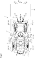
- Fig. 6
- is a plan view illustrating a front axle frame, a support body, and the like.
- Fig. 7
- is a front view of the support body.
- Fig. 8
- is a perspective view of the support body.
- Fig. 9
- is a front view of a lower portion of the support body.
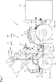
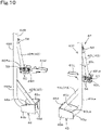
- Fig. 10
- is a perspective view of the lower portion of the support body.
- Fig. 11
- is a perspective view illustrating a first bracket, a first connection member, and the like.
- Fig. 12
- is a perspective view illustrating a first reinforcement member, the first joint member, the first connection member, and the like.
- Fig. 13
- is a side view illustrating the first reinforcement member, the first joint member, the first connection member, and the like.
- Hereinbelow, embodiments of a
riding management machine 1 according to the present invention will be described. -
Fig. 1 is a side view illustrating an embodiment of theriding management machine 1. - As illustrated in
Fig. 1 , theriding management machine 1 comprises atraveling vehicle 1A and aworking device 1B attached to thetraveling vehicle 1A. In theriding management machine 1, an operator can ride on thetraveling vehicle 1A and perform work (agricultural work) on an agricultural field using theworking device 1B. - As illustrated in
Figs. 1 to 4 , thetraveling vehicle 1A comprises avehicle body 2 and atraveling device 3 supporting thevehicle body 2 travelably. - In the present embodiment, a forward direction (a direction indicated by arrow A1 in
Fig. 1 ) of the operator (driver) sitting on an operator'sseat 4 provided on thevehicle body 2 is referred to as "front" or "forward", a rearward direction (a direction indicated by arrow A2 inFig. 1 ) of the operator is referred to as "rear" or "rearward", a leftward direction (a direction indicated by arrow B2 inFig. 2 ) of the operator is referred to as "left" or "leftward", and a rightward direction (a direction indicated by arrow B1 inFig. 2 ) of the operator is referred to as "right" or "rightward". A horizontal direction, which is orthogonal to a fore-and-aft direction (a direction indicated by arrow A3 inFig. 1 ), is referred to as a vehicle-width direction (refer to a direction indicated by arrow B3 inFig. 2 ). A direction separating from thevehicle body 2 that is the vehicle-width direction B3 is referred to as "outward" in the vehicle-width direction, and a direction approaching thevehicle body 2 that is the vehicle-width direction is referred to as "inward" in the vehicle-width direction. - As illustrated in
Fig. 1 , thevehicle body 2 comprises aprime mover 5, aclutch housing 6, a coupling frame 7, and a transmission case 8. - The
prime mover 5 is, for example, an engine and, specifically, a diesel engine. Theclutch housing 6 is coupled to a rear portion of theprime mover 5. A flywheel that reduces fluctuations in the torque of theprime mover 5 to stabilize the torque and a clutch that intermittently transmits power of theprime mover 5 transmitted thereto through the flywheel are housed in theclutch housing 6. The coupling frame 7 couples theclutch housing 6 and the transmission case 8 to each other. A transmission that speed-shifts power transmitted through the clutch is housed in the transmission case 8. Theprime mover 5, theclutch housing 6, the coupling frame 7, and the transmission case 8 are integrally coupled to each other to constitute a vehicle body frame 9. - The traveling
device 3 comprisesfront wheels 3F andrear wheels 3R. As illustrated inFig. 2 , thefront wheels 3F include a left front wheel 3FL disposed on the left side of thevehicle body 2 and a right front wheel 3FR disposed on the right side of thevehicle body 2. Therear wheels 3R include a left rear wheel 3RL disposed on the left side of thevehicle body 2 and a right rear wheel 3RR disposed on the right side of thevehicle body 2. - As illustrated in
Figs. 1 and2 , thevehicle body 2 comprises afront axle frame 10 fixed to a lower portion of theprime mover 5. Thefront axle frame 10 supports afront axle case 11. Afront axle 12 connected to thefront wheels 3F is housed in thefront axle case 11. - As illustrated in
Figs. 2 and6 , thefront axle frame 10 comprises aleft frame 10L, aright frame 10R, afront frame 10F, and anintermediate frame 10M. Theleft frame 10L is fixed to a lower left portion of theprime mover 5. Theright frame 10R is fixed to a lower right portion of theprime mover 5. Theleft frame 10L and theright frame 10R extend parallel to each other in the fore-and-aft direction. Thefront frame 10F connects a front end of theleft frame 10L and a front end of theright frame 10R to each other. Theintermediate frame 10M connects a fore-and-aft intermediate portion of theleft frame 10L and a fore-and-aft intermediate portion of theright frame 10R to each other. Aweight 27 is attached to a front portion of thefront frame 10F. - The operator'
seat 4 is provided on a rear portion of thevehicle body 2. The operator'sseat 4 is provided between the left rear wheel 3RL and the right rear wheel 3RR. Asteering wheel 13 operable to steer steerable wheels (thefront wheels 3F in the present embodiment) is provided in front of the operator'sseat 4. An attachingdevice 14 is provided on the rear portion of thevehicle body 2. The workingdevice 1B is detachably attached to the attachingdevice 14. The attachingdevice 14 is constituted of a three-point linkage mechanism and comprises onetop linkage 14A and twolower linkages 14B. The attachingdevice 14 is capable of raising and lowering the workingdevice 1B relative to thevehicle body 2. For example, a vegetable (e.g., onion) transplanter that serves as the workingdevice 1B can be attached to the attachingdevice 14. Note that the workingdevice 1B is not limited to the transplanter and may be any device that performs work on an agricultural field. Further, the workingdevice 1B may be attached to a front portion of thevehicle body 2. - A
hood 15 is provided in front of the operator'sseat 4. Thehood 15 is attached to the vehicle body frame 9 so as to cover theprime mover 5. Thehood 15 is openable upward. Specifically, when thehood 15 is opened, a front portion of thehood 15 is raised with a rear portion thereof serving as a fulcrum (refer to a virtual line inFig. 1 ). - As illustrated in
Fig. 2 , steps 16 are provided sideward and forward (obliquely forward) of the operator'sseat 4. Thesteps 16 include afirst step 16L and asecond step 16R. Thefirst step 16L is provided on one side in the vehicle-width direction (leftward) of the operator'sseat 4. Thesecond step 16R is provided on the other side in the vehicle-width direction (rightward) of the operator'sseat 4. - A first rising
portion 17L is provided on a front portion of thefirst step 16L. The first risingportion 17L is located leftward and forward of the operator'sseat 4 and rises forwardly upward slantwise as illustrated inFigs. 1 and4 . A pedal shaft of aclutch pedal 18 penetrates the first risingportion 17L. Afoothold portion 19 for an operator (driver) to put his/her foot thereon when the operator gets on or off the travelingvehicle 1A is provided on a left portion of thefirst step 16L. - A second rising
portion 17R is provided on a front portion of thesecond step 16R. The second risingportion 17R is located rightward and forward of the operator'sseat 4 and rises forwardly upward slantwise. Pedal shafts ofbrake pedals portion 17R. - As illustrated in
Fig. 5 , the travelingvehicle 1A comprises asteering device 21. Thesteering device 21 comprises thesteering wheel 13, a steeringshaft 22 rotatable along with rotation of thesteering wheel 13, and an assist mechanism (power steering mechanism) 23 that assists steering of thesteering wheel 13. Theassist mechanism 23 incudes a hydraulic pump P1, acontrol valve 24 supplied with a hydraulic fluid delivered from the hydraulic pump P1, and asteering cylinder 25 configured to be operated by thecontrol valve 24. Thecontrol valve 24 is a solenoid valve operated in accordance with a control signal. For example, thecontrol vale 24 is a 3-position switching valve configured to be switched by, for example, movement of a spool. Thecontrol valve 24 is also configured to be switched by steering of the steeringshaft 22. Thesteering cylinder 25 is connected to arms (knuckle arms) 26 for changing the direction of the front wheels 3FL and 3FR. - When the
steering wheel 13 is operated, a switching position and an opening degree of thecontrol valve 24 are changed in response to the operation of thesteering wheel 13, and a piston rod of thesteering cylinder 25 moves leftward or rightward according to the switching position and the opening degree of thecontrol valve 24. Accordingly, a direction of steering thefront wheels 3F can be changed. However, the configuration of thesteering device 21 is not limited to the above-described configuration. - As illustrated in
Figs. 1 to 4 , the travelingvehicle 1A comprises aposition detector 30 that detects a position (traveling position) of the travelingvehicle 1A (vehicle body 2). Theposition detector 30 is attached to a support body 40 (described later) and supported on thevehicle body 2. - The
position detector 30 receives a signal of a positioning satellite and detects the position of thevehicle body 2 based on the received signal. That is, theposition detector 30 detects positional information of thevehicle body 2 using a global navigation satellite system (GNSS). For example, a global positioning system (GPS) is used as the GNSS. For example, a real time kinematic (RTK) positioning method is used as a positioning method using a positioning satellite system. - The
position detector 30 detects its own position (positioning information including its latitude and longitude) using the satellite positioning system. That is, theposition detector 30 receives a signal (e.g., a position of the positioning satellite, a transmission time, or correction information) transmitted from the positioning satellite and detects the position (latitude and longitude) based on the received signal. Preferably, theposition detector 30 detects, as its own position (latitude and longitude), a position corrected based on, for example, a correction signal from a base station (reference station) configured to receive a signal from the positioning satellite. Alternatively, theposition detector 30 may include an inertial measurement device such as a gyroscopic sensor or an acceleration sensor and detect a position corrected by the inertial measurement device as its own position. - As illustrated in
Fig. 5 , the travelingvehicle 1A comprises acontroller 31. - The
position detector 30, a travelingdetector 32 of a traveling system, and awork detector 33 of a work system are connected to thecontroller 31. Thus, thecontroller 31 is configured or programmed to acquire the position detected by theposition detector 30, a detection value detected by the travelingdetector 32, and a detection value detected by thework detector 33. - Examples of the traveling
detector 32 include a crank sensor, a cam sensor, an engine rotation sensor, an accelerator sensor, a vehicle speed sensor, and a steering angle sensor. Examples of thework detector 33 include a lever detection sensor and a PTO rotation sensor. - The
controller 31 controls the traveling system and the work system in the travelingvehicle 1A. Thecontroller 31 controls, for example, a rotation speed of the prime mover 5 (engine), the vehicle speed, or the steering angle of thesteering device 21 based on the detection value detected by the travelingdetector 32. Further, thecontroller 31 controls, for example, raising and lowering of a lifting device that raises and lowers the working device attached to the travelingvehicle 1A or a PTO rotation speed based on the detection value detected by thework detector 33. - The
controller 31 comprises asteering control unit 34. Thesteering control unit 34 is constituted of, for example, an electric or electronic component provided in thecontroller 31, or a program stored in thecontroller 31. - The steering controller 34 (controller 31) automatically controls steering of the traveling
vehicle 1A (automatic steering control) based on a predetermined planned traveling route (planned traveling path). As illustrated inFig. 5 , the travelingvehicle 1A comprises, for example, a switch (command switch) 35 that enables or disables the automatic steering control. Thecommand switch 35 is connected to thecontroller 31. Thecommand switch 35 is switchable between ON and OFF. Thecommand switch 35 enables the automatic steering control when thecommand switch 35 is ON and disables the automatic steering control when thecommand switch 35 is OFF. Thecommand switch 35 is installed near the operator'sseat 4 and operable by an operator (driver). - When the automatic steering control is enabled, the
steering control unit 34 sets the switching position and the opening degree of thecontrol valve 24 so that at least the traveling position (the position detected by the position detector 30) of the travelingvehicle 1A (traveling body 2) coincides with the planned traveling route. In other words, when the automatic steering control is enabled, thecontroller 31 determines a moving direction and a moving amount of the piston rod of the steering cylinder 25 (the steered direction and angle of thefront wheels 3F) so that the traveling position of the travelingvehicle 1A coincides with the planned traveling route. - Specifically, when the automatic steering control is enabled, the
steering control unit 34 compares the traveling position of the travelingvehicle 1A (vehicle body 2) detected by theposition detector 30 with a position indicated by the planned traveling route (planned traveling position). When the traveling position coincides with the planned traveling position, the steeringcontroller 34 holds the steering angle and the steering direction of thesteering wheel 13 of the steering device 21 (the steered angle and direction of thefront wheels 3F) unchanged (maintains the opening degree and the switching position of thecontrol valve 24 unchanged). When the traveling position does not coincide with the planned traveling position, the steeringcontroller 34 changes the rotation angle and/or the rotation direction of thesteering wheel 13 of the steering device 21 (changes the opening degree and/or the switching position of the control valve 24) so as to eliminate a deviation (deviation amount) of the traveling position from the planned traveling position. - When the automatic steering control is disabled, the
steering control unit 34 sets, for example, the steered direction and angle of thefront wheels 3F, or the vehicle speed in accordance with an operation of an operator (e.g., an operation of an operator on thesteering wheel 13 or an operation of an operator on an accelerator). That is, an operator can manually change the direction of the travelingvehicle 1A (vehicle body 2) through the steeringcontroller 34. - As illustrated in
Fig. 5 , the travelingvehicle 1A comprises adisplay 36. Thedisplay 36 is disposed, for example, near the operator'sseat 4. An operator sitting on the operator'sseat 4 can visually recognize and operate thedisplay 36. Thedisplay 36 is configured to display various pieces of information and comprises a displaying part (screen) 36a constituted of, for example, a liquid crystal panel or a touch panel. - The
display 36 comprises a referenceline setting unit 36b and a travelingsetting unit 36c. The referenceline setting unit 36b and the travelingsetting unit 36c are each constituted of, for example, an electric or electronic component provided in thedisplay 36, or a program stored in thedisplay device 36 or the like. The referenceline setting unit 36b sets a reference line to be referred to during traveling. The travelingsetting unit 36c performs setting related to traveling of the travelingvehicle 1A. The travelingsetting unit 36c sets the planned traveling route for the travelingvehicle 1A (vehicle body 2) based on the reference line set by manual traveling. Thedisplay unit 36a (display 36) is configured to display the planned traveling route. - The
display 36 comprises astorage 36d. Thestorage 36d is, for example, a nonvolatile memory. A start position and an end position of the reference line are stored in thestorage unit 36d when the reference line is determined by straight traveling of the travelingvehicle 1A. Specifically, when the travelingvehicle 1A is located at a work start position and apath setting button 36e (refer toFig. 5 ) displayed on thedisplay 32 is pressed, a start point is stored (registered) in thestorage unit 36d as positional information acquired by the satellite positioning system. Next, by the manual operation, the travelingvehicle 1A is caused to travel straight and the working device performs work, and thepath setting button 36e is pressed when the travelingvehicle 1A comes to a work end position at an end of an agricultural field. Accordingly, an end point is stored (registered) as positional information in thestorage unit 36d, and a reference line that is a straight line connecting the start point to the end point is stored (registered) in thestorage unit 36d. The planned traveling route is set as being parallel to the reference line. Any number of planned traveling routes is set according to, for example, the area of the agricultural field. - The traveling
vehicle 1A described above is caused to travel along the planned traveling route by automatically steering thevehicle body 3 based on the planned traveling route through the automatic steering control performed by the steering controller 28. - Hereinbelow, the
support body 40 supporting theposition detector 30 will be described. - As illustrated in
Figs. 1 to 3 , thesupport body 40 supports theposition detector 30 above thehood 15. A signal from the positioning satellite is less likely to be blocked by supporting theposition detector 30 above thehood 15. Thus, a receiving sensitivity of theposition detector 30 can be improved. Theposition detector 30 is disposed rearward of thefront axle 12 above thehood 15. Theposition detector 30 is disposed rearward of a fore-and-aft center of the hood 15 (closer to a rear portion of the hood 30). Accordingly, as indicated by the virtual line inFig. 1 , when thehood 15 is opened, interference between thehood 15 and theposition detector 30 can be prevented. - As illustrated in
Figs. 3 ,7 , and8 , thesupport body 40 comprises a pair of struts and aconnection portion 40C. The pair of struts comprises afirst strut 40L and asecond strut 40R. Thefirst strut 40L, thesecond strut 40R and theconnection portion 40C that constitute thesupport body 40 are each formed of a hollow pipe (round pipe). - The working
vehicle 2 does not include a rollover protection system (ROPS) for protecting an operator sitting on the operator'sseat 4 in the event of rollover. Thesupport body 40 does not serve as the ROPS. - The
first strut 40L is erected on one side (left side) in the vehicle-width direction of thevehicle body 2. Thesecond strut 40R is erected on the other side (right side) in the vehicle-width direction of thevehicle body 2. Thefirst strut 40L and thesecond strut 40R are erected forward of the operator'sseat 4 and rearward of thefront axle 12. Although, in the example illustrated inFig. 1 , thefirst strut 40L and thesecond strut 40R extend vertically upward, thefirst strut 40L and thesecond strut 40R may be slanted forward or rearward. Theconnection portion 40C extends in the vehicle-width direction and connects a top of thefirst strut 40L and a top of thesecond strut 40R to each other above thehood 15. - The
position detector 30 is attached to theconnection portion 40C. Theposition detector 30 is attached to an upper portion of the connection portion 30C. As illustrated inFig. 2 , theposition detector 30 and theconnection portion 40C overlap each other in plan view. - As illustrated in
Figs. 7 and8 , anattachment portion 41 for attaching theposition detector 30 thereto is provided on the upper portion of theconnection portion 40C. Theattachment portion 41 is disposed on the vehicle-width directional center of theconnection portion 40C. Theattachment portion 41 comprises a pair ofsupport plates plate 41U. Theposition detector 30 is attached to an upper face of the placingplate 41U with, for example, a bolt. Thesupport plate 41L is fixed to a left portion of a lower face of the placingplate 41U by, for example, welding. Thesupport plate 41R is fixed to a right portion of the lower face of the placingplate 41U by, for example, welding. Thesupport plates support plates connection portion 40C by, for example, welding. Specifically, each of thesupport plates cutout 41a having a circular arc shape (refer toFig. 1 ), and thecutout 41a is welded along an outer peripheral face of theconnection portion 40C. - The
position detector 30 comprises adevice body 30a and anantenna 30b. A height of theconnection portion 40C is set so that a height of the position detector 30 (specifically, a height of an upper face of thedevice body 30a) is 2 m or less from the ground. - As illustrated in
Fig. 1 , the height of theposition detector 30 is higher than a height of an upper end of the operator's seat 4 (an upper end of a backrest) and higher than a height of an eye level of an operator sitting on the operator'sseat 4. This prevents theposition detector 30 from obstructing a forward view of the operator. Further, the height of theposition detector 30 is higher than a height of an upper end of thesteering wheel 13. - An upper portion and a lower portion of the
support body 40 are constituted of separate members. Specifically, thesupport body 40 comprises a lower section 410 and anupper section 402. A combination of thelower section 401 and theupper section 402 constitutes thesupport body 40. - The
lower section 401 comprises a lower portion of thefirst strut 40L and a lower portion of thesecond strut 40R. Thelower section 401 is formed of pipes constituting the lower portion of thefirst strut 40L and the lower portion of thesecond strut 40R. Theupper section 402 comprises theconnection portion 40C, an upper portion of thefirst strut 40L, and an upper portion of thesecond strut 40R. Theupper section 402 is formed of one pipe bent in a portal shape (inverted U-shape). That is, one pipe is formed as theupper section 402 including theconnection portion 40C, the upper portion of thefirst strut 40L, and the upper portion of thesecond strut 40R that constitute theupper section 402 are formed of one pipe. - The
lower section 401 is attached to thevehicle body 2. Theupper section 402 is detachably attached to thelower section 401. As illustrated inFig. 7 , theupper section 402 comprises, at respective lower portions thereof, small-diameter portions 402a. The smaller-diameter portions 402a have an outer diameter smaller than an inner diameter of thelower section 401. Theupper section 402 is detachably attached to thelower section 401 by inserting the small-diameter portions 402a of theupper section 402 into thelower section 401 from respective upper ends of thelower section 401 and fixing them with fasteners (bolts and nuts) 51. - As illustrated in
Figs. 6 ,8 , and9 , thefirst strut 40L comprises a first vertical portion 40La and a first traversal portion 40Lb. The first vertical portion 40La extends in the vertical direction. The first traversal portion 40Lb extends inward in the vehicle-width direction (rightward) from a lower end of the first vertical portion 40La. The first traversal portion Lb is provided on a lower end of thefirst strut 40L. In other words, the first traversal portion 40Lb extending inward in the vehicle-width direction (rightward) is provided on the lower end of thefirst strut 40L. - The
second strut 40R comprises a second vertical portion 40Ra and a second traversal portion 40Rb. The second vertical portion 40Ra extends in the vertical direction. The second traversal portion 40Rb extends inward in the vehicle-width direction (leftward) from a lower end of the second vertical portion 40Ra. The second traversal portion 40Rb is provided on a lower end of thesecond strut 40R. In other words, the second traversal portion 40Rb extending inward in the vehicle-width direction (leftward) is provided on the lower end of thesecond strut 40R. - As illustrated in
Figs. 2 ,4 ,6 , and11 , the lower portion (lower section 401) of thesupport body 40 is attached to the vehicle body 2 (specifically, to the front axle frame 10) through afirst bracket 45 and asecond bracket 46. Thefirst bracket 45 is attached to one side (left side) in the vehicle-width direction of thevehicle body 2. Thesecond bracket 46 is attached to the other side (right side) in the vehicle-width direction of thevehicle body 2. - The
first bracket 45 projects outward in the vehicle-width direction (leftward) from a left portion of thefront axle frame 10. Thesecond bracket 46 projects outward in the vehicle-width direction (rightward) from a right portion of thefront axle frame 10. - As illustrated in
Fig. 2 , thefirst bracket 45 and thesecond bracket 46 are disposed rearward of thefront axle 12. Upper portions of thefirst bracket 45 and thesecond bracket 46 are covered by thehood 15. In other words, thefirst bracket 45 and thesecond bracket 46 entirely overlap thehood 15 in plan view. - As illustrated in
Figs. 6 to 11 , thefirst bracket 45 comprises a firstlower plate 45a, a firstfront plate 45b, a firstrear plate 45c, and afirst side plate 45d. As illustrated inFIG. 9 , the firstlower plate 45a comprises a first horizontal portion 45a1 and a first vertical portion 45a2. The first horizontal portion 45a1 is disposed with one face facing up and the other face facing down. The first vertical portion 45a2 bends from a left end of the first horizontal portion 45a1 and extends downward. The firstfront plate 45b is connected to a front edge of the firstlower plate 45a. The firstrear plate 45c is connected to a rear edge of the firstlower plate 45a. The firstfront plate 45b and the firstrear plate 45c are disposed parallel to each other with a space therebetween in the fore-and-aft direction. Thefirst side plate 45d is disposed with one face facing left and the other face facing right. The one face of thefirst side plate 45d is connected to a right end of the firstfront plate 45b, a right end of the firstrear plate 45c, and a right end of the firstlower plate 45a. - The
second bracket 46 comprises a secondlower plate 46a, a secondfront plate 46b, a secondrear plate 46c, and asecond side plate 46d. As illustrated inFig. 9 , the secondlower plate 46a comprises a second horizontal portion 46a1 and a second vertical portion 46a2. The second horizontal portion 46a1 is disposed with one face facing up and the other face facing down. The second vertical portion 46a2 bends from a right end of the second horizontal portion 46a1 and extends downward. The secondfront plate 46b is connected to a front edge of the secondlower plate 46a. The secondrear plate 46c is connected to a rear edge of the secondlower plate 46a. The secondfront plate 46b and the secondrear plate 46c are disposed parallel to each other with a space therebetween in the fore-and-aft direction. Thesecond side plate 46d is disposed with one face facing right and the other face facing left. The one face of thefirst side plate 45d is connected to a left end of the firstfront plate 45b, a left end of the firstrear plate 45c, and a left end of the firstlower plate 45a. - As illustrated in
Fig. 6 , thefirst side plate 45d of thefirst bracket 45 is detachably attached to theleft frame 10L of thefront axle frame 10 with a fastener (a bolt and a nut) 52. Thesecond side plate 46d of thesecond bracket 46 is detachably attached to theright frame 10R of thefront axle frame 10 with a fastener (a bolt and a nut) 53. However, thefirst bracket 45 and thesecond bracket 46 may be attached to the vehicle body frame 9 (e.g., a lower portion of a side face of the prime mover 5). - As illustrated in, for example,
Figs. 6 ,8 , and9 , the first traversal portion 40Lb of thefirst strut 40L is fixed to the firstlower plate 45a of thefirst bracket 45. The first traversal portion 40Lb extends rightward in contact with the upper face of the firstlower plate 45a of the first bracket 45 (the one face of the first horizontal portion 45a1) and abuts against, at a right end thereof, the left face (the one face) of thefirst side plate 45d. The first traversal portion 40Lb is fixed to thefirst bracket 45 by, for example, welding. Accordingly, the lower portion of thefirst strut 40L is fixed to thefirst bracket 45. - The second traversal portion 40Rb of the
second strut 40R is fixed to the secondlower plate 46a of thesecond bracket 46. The second traversal portion 40Rb extends leftward in contact with the upper face of the secondlower plate 46a of the second bracket 46 (the one face of the second horizontal portion 46a1) and abuts against, at a left end thereof, the right face (the one face) of thesecond side plate 46d. The second traversal portion 40Rb is fixed to thesecond bracket 46 by, for example, welding. Accordingly, the lower portion of thesecond strut 40R is fixed to thesecond bracket 46. - As illustrated in
Figs. 1 to 4 , thesupport body 40 comprisesreinforcement members first strut 40L and thesecond strut 40R) to thevehicle body 2. Thereinforcement members main reinforcement members 42 andsub reinforcement members 43. - As illustrated in
Figs. 6 , and8 to 10 , themain reinforcement members 42 include a firstmain reinforcement member 42L and a secondmain reinforcement member 42R. The firstmain reinforcement member 42L reinforces thefirst strut 40L. The secondmain reinforcement member 42R reinforces thesecond strut 40R. - As illustrated in
Figs. 6 to 10 , thesub reinforcement members 43 include a firstsub reinforcement member 43L and a secondsub reinforcement member 43R. The firstsub reinforcement member 43L reinforces thefirst strut 40L in a direction different from a reinforcing direction of the firstmain reinforcement member 42L. The secondsub reinforcement member 43R reinforces thesecond strut 40R in a direction different from a reinforcing direction of the secondmain reinforcement member 42R. - Hereinbelow, the first
main reinforcement member 42L and the firstsub reinforcement member 43L may be collectively referred to as "first reinforcement members", and the secondmain reinforcement member 42R and the secondsub reinforcement member 43R may be collectively referred to as "second reinforcement members". - The first reinforcement members (the first
main reinforcement member 42L and the firstsub reinforcement member 43L) and the second reinforcement members (the secondmain reinforcement member 42R and the secondsub reinforcement member 43R) connect thelower section 401 of thestruts 40 to thevehicle body 2. - As illustrated in
Figs. 1 ,2 , and4 , themain reinforcement members 42 extend rearward (specifically, obliquely downward and rearward) from vertically intermediate portions of the respective struts (thefirst strut 40L and thesecond strut 40R) to thevehicle body 2. The firstmain reinforcement member 42L connects the vertically intermediate portion of thefirst strut 40L to thevehicle body 2. The secondmain reinforcement member 42R connects the vertically intermediate portion of thesecond strut 40R to thevehicle body 2. - As illustrated in, for example,
Figs. 6 and8 , one end (upper end) of the firstmain reinforcement member 42L is joined to thefirst strut 40L. Specifically, the one end of the firstmain reinforcement member 42L is joined to the first vertical portion 40La of thefirst strut 40L. The first vertical portion 40La is provided with aprojection piece 44L projecting rearward. The one end of the firstmain reinforcement member 42L is joined to theprojection piece 44L with a fastener (a bolt and a nut) 54. - As illustrated in, for example,
Figs. 1 ,12 , and13 , the other end (lower end) of the firstmain reinforcement member 42L is joined to thefirst step 16L. Specifically, the other end of the firstmain reinforcement member 42L is joined to the first risingportion 17L of thefirst step 16L. More specifically, the other end of the firstmain reinforcement member 42L is joined to the first risingportion 17L of thefirst step 16L through a firstjoint member 61L. - As illustrated in
Figs. 6 and13 , the firstjoint member 61L comprises afront plate 61a, arear plate 61b, alower plate 61c, and anupper plate 61d. Thefront plate 61a and therear plate 61b are spaced apart from each other in the fore-and-aft direction and extend parallel to each other in the vehicle-width direction. Thelower plate 61c connects a lower end of thefront plate 61a and a lower end of therear plate 61b to each other. Theupper plate 61d extends forward from an upper end of therear plate 61d to thefront plate 61a. As illustrated inFig. 13 , theupper plate 61d abuts against a lower face of an upper portion of the first risingportion 17L and is joined to the lower face with a fastener (a bolt and a nut) 55. - The other end of the first
main reinforcement member 42L is joined to thefront plate 61a through afirst connection member 62L. As illustrated inFigs. 12 and13 , thefirst connection member 61L comprises afirst member 621L and asecond member 622L. Thefirst member 621L comprises a vertical plate portion 621La and a horizontal plate portion 621Lb. Thevertical plate portion 621 La has one face facing front and the other face facing rear. The other face of thevertical plate portion 621 La abuts against thefront plate 61a. The vertical plate portion 621La is joined to thefront plate 61a of the firstjoint member 61L with a fastener (a bolt and a nut) 56. Thesecond member 622L has a plate shape, and has one face facing left and the other face facing right. Thesecond member 622L abuts against the vertical plate portion 621La and thehorizontal plate portion 621 Lb of thefirst member 621L and is integrated with thefirst member 621L by, for example, welding. - As illustrated in
Figs. 12 and13 , a connection piece 42La is provided on the other end of the firstmain reinforcement member 42L. The connection piece 42La is joined to thesecond member 622L of thefirst connection member 62L with a fastener (a bolt and a nut) 57. Accordingly, the firstmain reinforcement member 42L and the firstjoint member 61L (front plate 61a) are joined to each other through thefirst connection member 62L. Further, the firstmain reinforcement member 42L is joined to the first risingportion 17L of thefirst step 16 through the firstjoint member 61L. - As illustrated in, for example,
Figs. 6 and8 , one end of the secondmain reinforcement member 42R is joined to thesecond strut 40R. Specifically, the one end of the secondmain reinforcement member 42R is joined to the second vertical portion 40Ra of thesecond strut 40R. The second vertical portion 40Ra is provided with aprojection piece 44R projecting rearward. The one end of the secondsub reinforcement member 43R is joined to theprojection piece 44R with a fastener (a bolt and a nut) 58. - The other end of the second
main reinforcement member 42R is joined to thesecond step 16R. A joining structure between the other end of the secondmain reinforcement member 42R and thesecond step 16R is similar to a joining structure between the other end of the firstmain reinforcement member 42L and thefirst step 16L. Thus, only main points will be described, and detailed illustration and description will be omitted. - As illustrated in
Fig. 2 , the other end of the secondmain reinforcement member 42R is joined to the second risingportion 17R of thesecond step 16R. Specifically, the other end of the secondmain reinforcement member 42R is joined to the second risingportion 17R of thesecond step 16R through a secondjoint member 61R (refer toFigs. 6 to 8 ). The configuration of the secondjoint member 61R is similar to the configuration of the firstjoint member 61L. Specifically, the shape of the secondjoint member 61R and the shape of the firstjoint member 61L are symmetric with respect to the center of thevehicle body 2 in the vehicle-width direction. - As illustrated in
Figs. 6 ,8 , and10 , a connection piece 42Ra is provided on the other end of the secondmain reinforcement member 42R. The connection piece 42Ra is joined to thesecond connection member 62R with a fastener (a bolt and a nut) 59. The configuration of thesecond connection member 62R is similar to the configuration of thefirst connection member 62L. Specifically, the shape of thesecond connection member 62R and the shape of thefirst connection member 62L are symmetric with respect to the center of thevehicle body 2 in the vehicle-width direction. Thesecond connection member 62R is joined to the secondjoint member 61R with a fastener (a bolt and a nut) 60. Accordingly, the secondmain reinforcement member 42R and the secondjoint member 61R are joined to each other through thesecond connection member 62R. Further, the secondmain reinforcement member 42R is joined to the second risingportion 17R of thesecond step 16 through the secondjoint member 61R. - As described above, the first
main reinforcement member 42L that reinforces thefirst strut 40L is joined to thefirst step 16 through the firstjoint member 61L. Further, the secondmain reinforcement member 42R that reinforces thesecond strut 40R is joined to thesecond step 16 through the secondjoint member 61R. Thus, thefirst strut 40L and thesecond strut 40R can be supported and reinforced by the firstmain reinforcement member 42L and the secondmain reinforcement member 42R from behind (obliquely below and behind). Accordingly, it is possible to increase the strength (stiffness) of thesupport body 40 against forces applied thereto from front. - The first
main reinforcement member 42L and the secondmain reinforcement member 42R may extend forward (specifically, obliquely downward and forward) from the vertically intermediate portions of therespective struts vehicle body 2. In this case, the firstmain reinforcement member 42L and the secondmain reinforcement member 42R support and reinforce thefirst strut 40L and thesecond strut 40R from front (obliquely below and front). Thus, it is possible to increase the strength (stiffness) of thesupport body 40 against forces applied thereto from behind. - As illustrated in
Figs. 3 and4 , thesub reinforcement members 43 extend inward in the vehicle-width direction from vertically intermediate portions (specifically, vertically intermediate portions of the lower section 401) of the respective struts (thefirst strut 40L and thesecond strut 40L) to thevehicle body 2. The firstsub reinforcement member 43L connects the vertically intermediate portion of thefirst strut 40L to thevehicle body 2. The secondsub reinforcement member 43R connects the vertically intermediate portion of thesecond strut 40R to thevehicle body 2. - As illustrated in
Fig. 8 and the like, themain reinforcement members 42 and thesub reinforcement members 43 are joined to therespective struts main reinforcement members 42 are joined to thestruts sub reinforcement members 43 are joined to thestruts main reinforcement members 42 are joined to thestruts sub reinforcement members 43 are joined to thestruts - As illustrated in
Fig. 9 , the firstsub reinforcement member 43L is joined at one end (upper end) thereof to the first vertical portion 40La and joined at the other end (lower end) thereof to the first traversal portion 40Lb and the first bracket 45 (first side plate 45d). The secondsub reinforcement member 43R is joined at one end (upper end) thereof to the second vertical portion 40Ra and joined at the other end (lower end) thereof to the second traversal portion 40Rb and the second bracket 46 (second side plate 46d). - The first
sub reinforcement member 43L can reinforce thefirst strut 40L in the vehicle-width direction, which is different from the reinforcing direction of the firstmain reinforcement member 42L. Further, the secondsub reinforcement member 43R can reinforce thesecond strut 40R in the vehicle-width direction, which is different from the reinforcing direction of the secondmain reinforcement member 42R. Accordingly, thefirst strut 40L and thesecond strut 40R are reinforced in both the fore-and-aft direction and the vehicle-width direction, which largely improves the strength (stiffness) of thesupport body 40. - Although the
support body 40 preferably comprises both themain reinforcement member 42 and thesub reinforcement member 43 as the reinforcement members, thesupport body 40 may include at least one of themain reinforcement member 42 and thesub reinforcement member 43. When thesupport body 40 comprises themain reinforcement member 42, thesupport body 40 preferably comprises both the firstmain reinforcement member 42L and the secondmain reinforcement member 42R. However, thesupport body 40 may include at least one of the firstmain reinforcement member 42L and the secondmain reinforcement member 42R. When thesupport body 40 comprises thesub reinforcement member 43, thesupport body 40 preferably comprises both the firstsub reinforcement member 43L and the secondsub reinforcement member 43R. However, thesupport body 40 may include at least one of the firstsub reinforcement member 43L and the secondsub reinforcement member 43R. - The
riding management machine 1 according to the above embodiment provides the following effects. - The
riding management machine 1 comprises: the travelingvehicle 1A including thevehicle body 2, the operator'sseat 4 provided on thevehicle body 2, and thehood 15 provided in front of the operator'sseat 4; the workingdevice 1B attached to the travelingvehicle 1A; theposition detector 30 to detect the position of thevehicle body 2 based on a signal from the positioning satellite; and thesupport body 40 supporting theposition detector 30 above thehood 15. Thesupport body 40 comprises the pair ofstruts vehicle body 2, theconnection portion 40C connecting the tops of the pair ofstruts reinforcement members respective struts vehicle body 2. - This configuration comprises the
support body 40 having a structure including thestruts reinforcement members support body 40 can reliably support theposition detector 30 on thevehicle body 2. Further, a signal from the positioning satellite is less likely to be blocked by supporting theposition detector 30 above thehood 15. Thus, the receiving sensitivity of theposition detector 30 can be improved. - The reinforcement members include the
main reinforcement members 42 extending forward or rearward from the vertically intermediate portions of therespective struts vehicle body 2, and thesub reinforcement members 43 extending in the vehicle-width direction from the vertically intermediate portions of therespective struts vehicle body 2. - According to this configuration, the
main reinforcement members 42 can improve the strength of thesupport body 40 against forces in the fore-and-aft direction, and thesub reinforcement members 43 can improve the strength of thesupport body 40 against forces in the vehicle-width direction. Thus, thesupport body 40 can stably and reliably support theposition detector 30. - The
main reinforcement members 42 and thesub reinforcement members 43 are joined to therespective struts main reinforcement members 42 are joined to thestruts sub reinforcement members 43 are joined to thestruts - According to this configuration, the
struts support body 40, which enables effective reinforcement of thesupport body 40. - The positions where the
main reinforcement members 42 are joined to thestruts sub reinforcement members 43 are joined to thestruts - According to this configuration, it is possible to effectively reinforce the strength of the
support body 40 against forces in the fore-and-aft direction in which thesupport body 40 is more prone to falling-down than in the vehicle-width direction by using themain reinforcement members 42 while reinforcing the strength of thesupport body 40 against forces in the vehicle-width direction by using thesub reinforcement members 43. - The
struts first strut 40L erected on the one side in the vehicle-width direction of thevehicle body 2, and thesecond strut 40R erected on the other side in the vehicle-width direction of thevehicle body 2. The reinforcement members include thefirst reinforcement members first strut 40L to thevehicle body 2, and thesecond reinforcement members second strut 40R to thevehicle body 2. - According to this configuration, the
struts reinforcement members vehicle body 2. Thus, the strength of thesupport body 40 is improved. - The
riding management machine 1 comprises: the travelingdevice 3 including thefront wheels 3F and therear wheels 3R and supporting thevehicle body 2 travelably; thefront axle frame 10 supporting thefront axle 12 joined to thefront wheels 3F; and thebrackets front axle frame 10 and is configured to have the lower portion of each of thestruts - According to this configuration, the lower portions of the
struts front axle frame 10 through thebrackets struts vehicle body 2. - Each of the
sub reinforcement members 43 is fixed at the lower end thereof to each of thebrackets - According to this configuration, the lower ends of the
sub reinforcement members 43 are attached to thefront axle frame 10 through thebrackets struts sub reinforcement members 43. - The
strut 40L comprises, at the lower end thereof, the traversal portion 40Lb extended inward in the vehicle-width direction and fixed to thebracket 45. Thestrut 40R comprises, at the lower end thereof, the traversal portion 40Rb extended inward in the vehicle-width direction and fixed to thebracket 46. - According to this configuration, it is possible to ensure a long abutting length between the lower end of the
strut 40L and thebracket 45 and between the lower end of thestrut 40R and thebracket 46. Thus, the lower ends of thestruts brackets - Each of the
sub reinforcement members 43 is fixed at the lower end thereof to each of the traversal portions 40Lb and 40Rb. - According to this configuration, the
sub reinforcement members 43 connect the vertically intermediate portions of thestruts struts - The
riding management machine 1 comprises thesteps 16 provided forward and sideward of the operator'sseat 4. Each of themain reinforcement members 42 is joined at one end thereof to each of thestruts steps 16. - According to this configuration, the
struts steps 16 through themain reinforcement members 42. Thus, thesteps 16 having high stiffness can receive forces applied to thestruts struts - The
support body 40 comprises thelower section 401 attached to thevehicle body 2, and theupper section 402 detachably attached to thelower section 401. Thelower section 401 comprises the lower portion of thefirst strut 40L and the lower portion of thesecond strut 40R. Theupper section 402 comprises theconnection portion 40C, the upper portion of thefirst strut 40L, and the upper portion of thesecond strut 40R. - According to this configuration, the
support body 40 can be separated into theupper section 402 and thelower section 401. Thus, thesupport body 40 can be easily attached to and detached from thevehicle body 2. - The
reinforcement members lower section 402 to thevehicle body 2. - According to this configuration, the
reinforcement members lower section 402 of thestruts reinforcement members struts - The
first strut 40L, thesecond strut 40R and theconnection portion 40C are each formed of a round pipe. - According to this configuration, the round pipes can achieve the
support body 40 having light weight and high strength. - In the above description, the embodiment of the present invention has been explained. However, all the features of the embodiment disclosed in this application should be considered just as examples, and the embodiment does not restrict the present invention accordingly. A scope of the present invention is illustrated not in the above-described embodiment but in claims, and is intended to include all modifications within and equivalent to a scope of the claims.
-
- 1
- Riding management machine
- 1A
- Traveling vehicle
- 1B
- Working device
- 2
- Vehicle body
- 3
- Traveling device
- 3F
- Front wheel
- 3R
- Rear wheel
- 4
- Operator's seat
- 10
- Front axle frame
- 12
- Front axle
- 15
- Hood
- 16
- Step
- 30
- Position detector
- 40
- Support body
- 40C
- Connection portion
- 40L
- First strut (strut)
- 40Lb
- First traversal portion (traversal portion)
- 40R
- Second strut (strut)
- 40Rb
- Second traversal portion (traversal portion)
- 401
- Lower section
- 402
- Upper section
- 42
- Main reinforcement member (reinforcement member)
- 42L
- First main reinforcement member (main reinforcement member)
- 42R
- Second main reinforcement member (main reinforcement member)
- 43
- Sub reinforcement member (reinforcement member)
- 43L
- First sub reinforcement member (reinforcement member)
- 43R
- Second sub reinforcement member (reinforcement member)
- 45
- First bracket (bracket)
- 46
- Second bracket (bracket)
Claims (13)
- A riding management machine, comprising:- a traveling vehicle comprising a vehicle body, an operator's seat provided on the vehicle body, and a hood provided in front of the operator's seat;- a working device attached to the traveling vehicle;- a position detector to detect a position of the vehicle body based on a signal from a positioning satellite; and- a support body supporting the position detector above the hood, wherein the support body comprises- a pair of struts erected on one and the other sides opposite to each other in a vehicle-width direction of the vehicle body,- a connection portion connecting tops of the pair of struts to each other, and- reinforcement members connecting the respective struts to the vehicle body.
- The riding management machine according to claim 1, wherein the reinforcement members comprise- main reinforcement members extending forward or rearward from vertically intermediate portions of the respective struts to the vehicle body, and- sub reinforcement members extending in the vehicle-width direction from vertically intermediate portions of the respective struts to the vehicle body.
- The riding management machine according to claim 2, wherein the main reinforcement members and the sub reinforcement members are joined to the respective struts so that positions where the main reinforcement members are joined to the struts are offset upward or downward from positions where the sub reinforcement members are joined to the struts.
- The riding management machine according to claim 3, wherein the positions where the main reinforcement members are joined to the struts are above the positions where the sub reinforcement members are joined to the struts.
- The riding management machine according to any one of claims 1 to 4, wherein- the struts comprise a first strut erected on the one side in the vehicle-width direction of the vehicle body, and a second strut erected on the other side in the vehicle-width direction of the vehicle body, and- the reinforcement members comprise a first reinforcement member connecting a vertically intermediate portion of the first strut to the vehicle body, and a second reinforcement member connecting a vertically intermediate portion of the second strut to the vehicle body.
- The riding management machine according to any one of claims 2 to 4, further comprising:- a traveling device including front wheels and rear wheels and supporting the vehicle body travelably;- a front axle frame supporting a front axle joined to the front wheels; and- brackets each of which is attached to the front axle frame and is configured to have a lower portion of each of the struts fixed thereto.
- The riding management machine according to claim 6, wherein each of the sub reinforcement members is fixed at a lower end thereof to each of the brackets.
- The riding management machine according to claim 6 or 7, wherein each of the struts includes, at a lower end thereof, a traversal portion extended inward in the vehicle-width direction and fixed to each of the brackets.
- The riding management machine according to claim 8, wherein each of the sub reinforcement members is fixed at a lower end thereof to each of the traversal portions.
- The riding management machine according to any one of claims 2 to 4 and 6 to 9, further comprising steps provided forward and sideward of the operator's seat, wherein each of the main reinforcement members is joined at one end thereof to each of the struts and is joined at the other end thereof to each of the steps.
- The riding management machine according to claim 5, wherein- the support body comprises a lower section attached to the vehicle body, and an upper section detachably attached to the lower section,- the lower section comprises a lower portion of the first strut and a lower portion of the second strut, and- the upper section comprises the connection portion, an upper portion of the first strut, and an upper portion of the second strut.
- The riding management machine according to claim 11, wherein the reinforcement members connect the lower section to the vehicle body.
- The riding management machine according to any one of claims 1 to 12, wherein the first strut, the second strut and the connection portion are each formed of a round pipe.
Applications Claiming Priority (2)
| Application Number | Priority Date | Filing Date | Title |
|---|---|---|---|
| JP2019175924A JP7314006B2 (en) | 2019-09-26 | 2019-09-26 | passenger management machine |
| PCT/JP2020/022094 WO2021059596A1 (en) | 2019-09-26 | 2020-06-04 | Ride-behind soil management machine |
Publications (2)
| Publication Number | Publication Date |
|---|---|
| EP4035516A1 true EP4035516A1 (en) | 2022-08-03 |
| EP4035516A4 EP4035516A4 (en) | 2023-11-01 |
Family
ID=75154825
Family Applications (1)
| Application Number | Title | Priority Date | Filing Date |
|---|---|---|---|
| EP20867798.9A Pending EP4035516A4 (en) | 2019-09-26 | 2020-06-04 | Ride-behind soil management machine |
Country Status (5)
| Country | Link |
|---|---|
| US (1) | US12077103B2 (en) |
| EP (1) | EP4035516A4 (en) |
| JP (1) | JP7314006B2 (en) |
| CN (1) | CN113924228B (en) |
| WO (1) | WO2021059596A1 (en) |
Families Citing this family (3)
| Publication number | Priority date | Publication date | Assignee | Title |
|---|---|---|---|---|
| JP7517084B2 (en) * | 2020-11-02 | 2024-07-17 | 井関農機株式会社 | Work vehicles |
| JP7593908B2 (en) * | 2021-10-07 | 2024-12-03 | ヤンマーホールディングス株式会社 | Management method, management terminal and management system |
| JP7517485B1 (en) | 2023-01-06 | 2024-07-17 | 井関農機株式会社 | Work vehicles |
Family Cites Families (12)
| Publication number | Priority date | Publication date | Assignee | Title |
|---|---|---|---|---|
| JPH0579053A (en) * | 1991-09-13 | 1993-03-30 | Kubota Corp | Back hoe installer |
| JP2003326984A (en) | 2002-05-13 | 2003-11-19 | Iseki & Co Ltd | Passenger management machine |
| JP3692101B2 (en) | 2002-07-22 | 2005-09-07 | セイレイ工業株式会社 | Passenger management machine |
| JP2007146512A (en) * | 2005-11-29 | 2007-06-14 | Yanmar Co Ltd | Working vehicle |
| JP5768689B2 (en) | 2011-12-01 | 2015-08-26 | 井関農機株式会社 | Passenger management machine |
| US20160355142A1 (en) * | 2015-06-08 | 2016-12-08 | Deere & Company | Bracket for mounting an electronic assembly |
| JP6646485B2 (en) * | 2016-03-16 | 2020-02-14 | 株式会社Ihiアグリテック | Passenger work vehicle |
| DE102017214354B3 (en) * | 2017-04-24 | 2018-09-27 | Deere & Company | Agricultural work vehicle with ground engaging means for transmitting shear forces |
| JP6881233B2 (en) * | 2017-10-27 | 2021-06-02 | 井関農機株式会社 | Work vehicle |
| JP6945421B2 (en) * | 2017-11-02 | 2021-10-06 | 三菱マヒンドラ農機株式会社 | Porting machine |
| JP6658717B2 (en) * | 2017-11-16 | 2020-03-04 | 井関農機株式会社 | Work vehicle |
| JP6995040B2 (en) * | 2018-12-05 | 2022-01-14 | 株式会社クボタ | Paddy field work machine |
-
2019
- 2019-09-26 JP JP2019175924A patent/JP7314006B2/en active Active
-
2020
- 2020-06-04 CN CN202080041765.3A patent/CN113924228B/en active Active
- 2020-06-04 WO PCT/JP2020/022094 patent/WO2021059596A1/en not_active Ceased
- 2020-06-04 EP EP20867798.9A patent/EP4035516A4/en active Pending
-
2021
- 2021-12-16 US US17/552,482 patent/US12077103B2/en active Active
Also Published As
| Publication number | Publication date |
|---|---|
| CN113924228A (en) | 2022-01-11 |
| US12077103B2 (en) | 2024-09-03 |
| EP4035516A4 (en) | 2023-11-01 |
| WO2021059596A1 (en) | 2021-04-01 |
| CN113924228B (en) | 2024-12-17 |
| JP7314006B2 (en) | 2023-07-25 |
| US20220109224A1 (en) | 2022-04-07 |
| JP2021048826A (en) | 2021-04-01 |
Similar Documents
| Publication | Publication Date | Title |
|---|---|---|
| KR102915055B1 (en) | Working vehicle | |
| KR102745013B1 (en) | Work vehicles and tractors | |
| US12077103B2 (en) | Riding management machine | |
| KR102644630B1 (en) | tractors and work vehicles | |
| JP7631598B2 (en) | Tractor | |
| JP2023024520A5 (en) | ||
| JP7624498B2 (en) | Work vehicles | |
| KR20210030255A (en) | Work vehicle | |
| KR102761119B1 (en) | work vehicle | |
| WO2019124258A1 (en) | Tractor and working vehicle | |
| JP2025092674A (en) | Work vehicles | |
| JP2020000141A (en) | Work vehicle | |
| JP7030540B2 (en) | Work vehicle | |
| JP7030541B2 (en) | Work vehicle | |
| JP2024106592A (en) | Work vehicles | |
| JP2023091608A (en) | Paddy work machine |
Legal Events
| Date | Code | Title | Description |
|---|---|---|---|
| STAA | Information on the status of an ep patent application or granted ep patent |
Free format text: STATUS: THE INTERNATIONAL PUBLICATION HAS BEEN MADE |
|
| PUAI | Public reference made under article 153(3) epc to a published international application that has entered the european phase |
Free format text: ORIGINAL CODE: 0009012 |
|
| STAA | Information on the status of an ep patent application or granted ep patent |
Free format text: STATUS: REQUEST FOR EXAMINATION WAS MADE |
|
| 17P | Request for examination filed |
Effective date: 20211216 |
|
| AK | Designated contracting states |
Kind code of ref document: A1 Designated state(s): AL AT BE BG CH CY CZ DE DK EE ES FI FR GB GR HR HU IE IS IT LI LT LU LV MC MK MT NL NO PL PT RO RS SE SI SK SM TR |
|
| DAV | Request for validation of the european patent (deleted) | ||
| DAX | Request for extension of the european patent (deleted) | ||
| REG | Reference to a national code |
Ref country code: DE Ref legal event code: R079 Free format text: PREVIOUS MAIN CLASS: A01B0069000000 Ipc: A01B0069040000 |
|
| A4 | Supplementary search report drawn up and despatched |
Effective date: 20230929 |
|
| RIC1 | Information provided on ipc code assigned before grant |
Ipc: B60R 11/00 20060101ALN20230925BHEP Ipc: B60R 16/02 20060101ALI20230925BHEP Ipc: B60R 11/02 20060101ALI20230925BHEP Ipc: A01B 69/04 20060101AFI20230925BHEP |