EP4035443B1 - Identyifying and reporting a fraudelent base station - Google Patents
Identyifying and reporting a fraudelent base station Download PDFInfo
- Publication number
- EP4035443B1 EP4035443B1 EP19797617.8A EP19797617A EP4035443B1 EP 4035443 B1 EP4035443 B1 EP 4035443B1 EP 19797617 A EP19797617 A EP 19797617A EP 4035443 B1 EP4035443 B1 EP 4035443B1
- Authority
- EP
- European Patent Office
- Prior art keywords
- base station
- radio devices
- received
- analyser device
- request message
- Prior art date
- Legal status (The legal status is an assumption and is not a legal conclusion. Google has not performed a legal analysis and makes no representation as to the accuracy of the status listed.)
- Active
Links
- 238000004590 computer program Methods 0.000 claims description 47
- 238000000034 method Methods 0.000 claims description 47
- 238000012545 processing Methods 0.000 claims description 32
- 230000007774 longterm Effects 0.000 claims description 29
- 238000004891 communication Methods 0.000 description 17
- 230000001413 cellular effect Effects 0.000 description 13
- 230000007246 mechanism Effects 0.000 description 10
- 238000010586 diagram Methods 0.000 description 7
- 238000001514 detection method Methods 0.000 description 6
- 230000003287 optical effect Effects 0.000 description 4
- 238000013459 approach Methods 0.000 description 3
- 238000005259 measurement Methods 0.000 description 3
- 230000011664 signaling Effects 0.000 description 3
- 230000001419 dependent effect Effects 0.000 description 2
- 230000006870 function Effects 0.000 description 2
- 238000012544 monitoring process Methods 0.000 description 2
- 230000002085 persistent effect Effects 0.000 description 2
- 230000035945 sensitivity Effects 0.000 description 2
- 239000007787 solid Substances 0.000 description 2
- 241001670157 Gymnura Species 0.000 description 1
- 230000005856 abnormality Effects 0.000 description 1
- 238000004458 analytical method Methods 0.000 description 1
- 238000013480 data collection Methods 0.000 description 1
- 230000003247 decreasing effect Effects 0.000 description 1
- 238000013461 design Methods 0.000 description 1
- 239000000284 extract Substances 0.000 description 1
- 238000010295 mobile communication Methods 0.000 description 1
- 239000013307 optical fiber Substances 0.000 description 1
- 238000002360 preparation method Methods 0.000 description 1
- 238000011897 real-time detection Methods 0.000 description 1
- 238000001228 spectrum Methods 0.000 description 1
- 238000012549 training Methods 0.000 description 1
- 238000012795 verification Methods 0.000 description 1
Images


Classifications
-
- H—ELECTRICITY
- H04—ELECTRIC COMMUNICATION TECHNIQUE
- H04W—WIRELESS COMMUNICATION NETWORKS
- H04W12/00—Security arrangements; Authentication; Protecting privacy or anonymity
- H04W12/12—Detection or prevention of fraud
- H04W12/121—Wireless intrusion detection systems [WIDS]; Wireless intrusion prevention systems [WIPS]
- H04W12/122—Counter-measures against attacks; Protection against rogue devices
-
- H—ELECTRICITY
- H04—ELECTRIC COMMUNICATION TECHNIQUE
- H04W—WIRELESS COMMUNICATION NETWORKS
- H04W60/00—Affiliation to network, e.g. registration; Terminating affiliation with the network, e.g. de-registration
Definitions
- Embodiments presented herein relate to identifying a fraudulent base station.
- Cellular telecommunication systems (2G systems, 3G systems, 4G systems, and 5G systems) are inherently built of a structure of interconnected cells, where a cell in this concept represents a coverage region served by a base station emitting wireless radio signals.
- base stations are equipped with powerful RF (Radio Frequency) transceivers and antennas in order to serve its coverage region.
- Cellular telecommunication systems are sometimes also referred as mobile communication systems (or networks), cellular (or wireless) communications networks, cellular radio systems or cellular networks.
- cellular (or wireless) communications networks cellular radio systems or cellular networks.
- several services might be offered, such as wireless Internet access, voice call service, short messaging services, and data sharing between users.
- each user is represented by its a user equipment (UE) to access cellular telecommunication system.
- UE user equipment
- Base stations are referred with various terms in different generations of cellular telecommunication systems. For example, they are termed as base transceiver station (BTS) in 2G systems, NodeB in 3G systems, eNodeB in 4G systems and gNodeB in 5G systems.
- Base stations emit radio signals structured according to related international standards. These signals include, for example, information about the base station itself, such as physical cell ID, signal frequency, and synchronization information. Each UE extracts this information from the received signals and calculate various parameter values, such as RSRP (Reference Signal Received Power).
- RSRP Reference Signal Received Power
- RSRP depends on several factors, for example the radiating power of the base station, the receiver sensitivity at the UE, and the location at which the measurements are made.
- a UE might sense RF signals simultaneously belonging to different base stations and select the one which is believed to best serve the UE based on some standard criteria.
- One criteria in this regard is the RSRP, since UEs tend to attach a base station resulting in highest possible RSSP. This base station is generally the one physically closest to the UE.
- Each UE is associated with a subscriber, needed for the UE to gain access to the cellular telecommunication system via the base station.
- Subscribers in the cellular telecommunication systems have a long-term identifier, denoted International Mobile Subscriber Identifier (IMSI), which for example could be embedded in a Universal Subscriber Identity Module (USIM).
- IMSI International Mobile Subscriber Identifier
- USIM Universal Subscriber Identity Module
- TMSI Temporary Mobile Subscriber Identity
- VLR Visitor Location Register
- the UE is requested to identify itself by the mobility management entity (MME), or similar, through the base station the UE is attempting to connect to.
- MME mobility management entity
- the UE commonly respond to this request by declaring its TMSI.
- related standards allow base stations to request the long-term identifier, the IMSI, instead of the TMSI, by sending a special IDENTITY REQUEST message, as a mechanism to resolve cases where TMSIs are lost or unreachable in the network.
- This mechanism might be exploited by malicious unauthorized base stations, hereinafter denoted a fraudulent base station, to capture the IMSI of the UE by transmitting IDENTITY REQUEST messages.
- the fraudulent base station might advertise itself as a preferred service point for the UE by radiating more powerful signals than other base station.
- Fraudulent base stations as referred to in the present disclosure are sometimes referred to with different terms, such as fake base stations, IMSI catchers, stingrays, rogue base stations, false base stations, and the like.
- fraudulent base station is used to denote a base station set up with the aim to capture the long-term identifier (such as the IMSI) of subscribers of UEs in a cellular telecommunication system.
- a fraudulent base station might achieve its goal by exploiting the procedures of Tracking Area Update (TAU), as used in 4G systems, and Location Area Update (LAU), as used in 3G systems, in such a way that the fraudulent base station advertise itself with a different Tracking Area Identity or Location Area Identity from legitimate base stations, and thereby convince the UE receiving signals from the fraudulent base station to initiate a TAU or LAU procedure that involves an attach procedure.
- TAU Tracking Area Update
- LAU Location Area Update
- 3G systems 3G systems
- Earlier approaches proposed for detection of fraudulent base stations can be categorized into two groups: (i) Device-assisted mechanisms, and (ii) Network-assisted mechanisms.
- a technician might manually observe the radio signals received at a specific location by using a radio device or spectrum analyzer to see if there is any suspicious signal that could be a sign for a possible fraudulent base station.
- a special kind of terminal is configured to send a Location Area Update Request message to a targeted base station, and then if a REJECT message is received from this base station in return, it is identified as a fraudulent base station.
- regular measurement reports of all UEs in a region of interest are first collected by the base stations and forwarded to a central unit for further processing. Then, anomaly detection is performed at the central unit by analyzing the collected measurement reports whilst comparing to the network topology of all legitimate base stations.
- WO 2016/206610 discloses user equipments (UEs) which report abnormalities to a server, when an unusual location update from a suspicious base station (BS) is detected.
- UEs user equipments
- EP 2 661 113 discloses a system wherein a BS is detected as being rogue, when the BS requests rapid successive re-registrations from a mobile terminal (MT) to force the MT to reveal its identifiers, at a rate above a pre-determined time interval.
- a BS is detected as being rogue, when the BS requests rapid successive re-registrations from a mobile terminal (MT) to force the MT to reveal its identifiers, at a rate above a pre-determined time interval.
- MT mobile terminal
- An object of embodiments herein is to provide efficient identification and reporting of fraudulent base stations not suffering from the issues noted above, or at least where the above issues are mitigated or reduced.
- a system for identifying a fraudulent base station comprises an analyser device and at least two radio devices.
- the system is configured to provide a report, from any of the at least two radio devices and to the analyser device upon that any of the at least two radio devices having received from a base station an identity request message for a long-term identifier of that any of the at least two radio devices, of the identity request message.
- the system is configured to identify, by the analyser device, the base station as fraudulent when reports of the same base station as received from at least two different ones of the at least two radio devices are received within a threshold time duration with respect to each other.
- a method for identifying a fraudulent base station is performed by an analyser device.
- the method comprises receiving a report, from any of at least two radio devices upon that any of the at least two radio devices having received from a base station an identity request message for a long-term identifier of that any of the at least two radio devices, of the identity request message.
- the method comprises identifying the base station as fraudulent when reports of the same base station as received from two different ones of the at least two radio devices are received within a threshold time duration with respect to each other.
- an analyser device for identifying a fraudulent base station.
- the analyser device comprises processing circuitry.
- the processing circuitry is configured to cause the analyser device to receive a report, from any of at least two radio devices upon that any of the at least two radio devices having received from a base station an identity request message for a long-term identifier of that any of the at least two radio devices, of the identity request message.
- the processing circuitry is configured to cause the analyser device to identify the base station as fraudulent when reports of the same base station as received from two different ones of the at least two radio devices are received within a threshold time duration with respect to each other.
- the computer program comprises computer program code which, when run on processing circuitry of an analyser device, causes the analyser device to perform a method according to the second aspect.
- a computer program product comprising a computer program according to the fourth aspect and a computer readable storage medium on which the computer program is stored.
- the computer readable storage medium could be a non-transitory computer readable storage medium.
- this method this system, this analyser device, this computer program and this computer program product enable instantaneous detection of fraudulent base stations without requiring any prior preparations, such as data collection related to legitimate network or region to be scanned.
- this method this system, this analyser device, this computer program and this computer program product enable false alarms to be decreased and the detection accuracy to be increased compared to training-based mechanisms for detecting fraudulent base stations.
- this method does not require any private information about the network or about the end-users, thus eliminating the risk of privacy issue to occur.
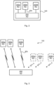
- Fig. 1 is a schematic diagram illustrating a simplification of a cellular telecommunication system 10 where embodiments presented herein can be applied.
- the cellular telecommunication system 10 comprises a base station 20, assumed to be a fraudulent base station.
- the fraudulent base station 20 transmit radio signals, as indicated by radiating arrows 30. It is assumed that the radio signals are received by radio devices (RD) 300a, 300b.
- the radio devices 300a, 300b provide reports to an analyser device (AD) 200 configured to identify the base station as fraudulent.
- the embodiments disclosed herein in particular relate to mechanisms for identifying a fraudulent base station 20 and reporting a fraudulent base station 20.
- an analyser device 200 a method performed by the analyser device 200, a computer program product comprising code, for example in the form of a computer program, that when run on processing circuitry of the analyser device 200, causes the analyser device 200 to perform the method.
- a radio device 300a:300N a method performed by the radio device 300a:300N
- a computer program product comprising code, for example in the form of a computer program, that when run on processing circuitry of the radio device 300a:300N, causes the radio device 300a:300N to perform the method.
- a system comprising the analyser device 200 and at least two radio devices 300a:300N.
- Fig. 2 illustrates a system 100 according to a first embodiment.
- each of the at least two radio devices 300a:300N is operatively connected to the analyser device 200 over a wired connection 40a.
- wired connection 40a As the skilled person, there could be different types of wired connections, such as optical fiber connections, coaxial cable connections, twisted pair cable connections, and the like.
- the analyser device 200 and the at least two radio devices 300a:300N are integrated, collocated, or provided, within one and the same physical entity, where this physical entity defines the system 100.
- the system 100 of Fig. 2 might be stationary and fixed to a critical location to enable continuous monitoring of any fraudulent base stations at such a critical location.
- the system 100 is configured to be mounted on a fixed location.
- the system 100 of Fig. 2 might alternatively be mounted on a vehicle (e.g. car, unmanned aerial vehicle (UAV), or the like) to enable intermittently monitoring of different locations.
- the system 100 is configured to be movable. In this sense, more than one such system 100 might be deployed to monitor different regions and configured to issue notifications of base stations deemed fraudulent.
- Fig. 3 illustrates a system 100 according to a second embodiment.
- each of the at least two radio devices 300a:300N is operatively connected to the analyser device 200 over a wireless connection 40b.
- at least two radio devices 300a':300N' are operatively connected to the analyser device 200 over a respective wireless connection.
- the analyser device 200 of the system 100 in Fig. 3 might reside in a cloud computational environment.
- the system 100 of Fig. 3 is by definition considered to be movable by the virtue of the at least two radio devices 300a:300N being movable.
- radio devices 300a:300N are positioned relative each other to receive signals from the same base station.
- radio devices 300a:300N form a first group of radio devices positioned relative each other to receive signals from one and the same base station and optional radio devices 300a':300N' form a second group of radio devices positioned relative each other to receive signals from one and the same base station
- Fig. 4 illustrating a method for identifying a fraudulent base station 20 as performed by the analyser device 200 according to an embodiment.
- each of the radio devices 300a:300N is configured to report any received identity request messages to the analyser device 200.
- the analyser device 200 is configured to perform S102: S102:
- the analyser device 200 receives a report.
- the report is received from any of at least two radio devices 300a:300N upon that any of the at least two radio devices 300a:300N having received from a base station 20 an identity request message for a long-term identifier of that any of the at least two radio devices 300a:300N.
- the report is of the identity request message.
- the base station 20 is identified as fraudulent based on the time difference between the reports.
- the analyser device 200 is configured to perform S104: S104: The analyser device 200 identifies the base station 20 as fraudulent when reports of the same base station 20 as received from two different ones of the at least two radio devices 300a:300N are received within a threshold time duration with respect to each other.
- the analyser 200 issues a notification when the base station 20 has been identified as fraudulent.
- the analyser device 200 is configured to perform (optional) step S110: S110: The analyser device 200 issues a notification of the thus identified fraudulent base station 20.
- the notification might be an alert message.
- the notification might by the analyser device 200 be sent to a network management entity.
- a notification in the form of an alert message might be sent by the analyzer device 200 to a network management entity for further handling of the fraudulent base station.
- the analyser device 200 only issues the notification in S110 only if one or more conditions is satisfied. Examples of such conditions will be disclosed next.
- One first condition relates to from how many radio devices 300a:300N reports have been received within the threshold time duration. That is, in some embodiments, the notification is in S110 only issued when the analyser device 200 has, for one and the same base station 20, received reports separated from each other at most by the threshold time duration from at least k radio devices 300a:300N, where k >1 is an integer. The higher the value of k , the higher the level of confidence that the base station 20 indeed is fraudulent.
- a certainty level can thereby be developed based on how many radio devices 300a:300N are reporting identity request message for a long-term identifier at the same time, or within a time interval given by the threshold time duration.
- the notification might be issued when k devices out of N receive the same identity request message for a long-term identifier at the same time from the same cell.
- One second condition relates to a certainty level for identifying the base station 20 indeed as fraudulent. That is, in some embodiments the analyser device 200 is configured to perform (optional) step S106: S106: The analyser device 200 determines a certainty level based on how many reports separated from each other at most by the threshold time duration have been received and how many at least two radio devices 300a:300N are operatively connected to the analyser device 200.
- the notification might then in S110 only be issued when the certainty level is above a certainty threshold value.
- One third condition relates to network statistics.
- the certainty level further is based on network statistics obtained by the analyser device 200.
- One fourth condition relates to verification performed by the analyser device 200.
- a fraudulent base station will send identity request messages for the long-term identifier of the radio devices 300a:300N much more often than a legitimate base station, regardless of if the radio devices 300a:300N have valid long-term identifiers or not.
- an identity request message for a long-term identifier could amount to less than 15% with respect to all identity request messages sent; for the remaining more than 85% the identity request message is for a short-term identifier.
- the analyser device 200 is configured to perform (optional) step S108: S108: The analyser device 200 verifies, by querying a database and before the notification is issued, that the base station 20 is not a registered base station.
- S108 is performed, S108 is performed before S110 is performed.
- the analyser device 200 might thus be configured to perform analyses on reports, if any, received from the radio devices 300a:300N and therefrom determine if there is any base station that should be considered as fraudulent based on the number of reports, content of the reports, and timestamps of the reports.
- the herein disclosed system 100 is flexible in the sense that parameters relating to any of the above four conditions might be set with regards to the sensitivity of the detection, for example by changing the value of the threshold time duration and also by adjusting from how many radio devices 300a:300N reports need to be received for a notification to be issued.
- the at least one radio device 300a:300N reports Cell ID, an identifier which unambiguously identifies a cell within a public land mobile network (PLMN). That is, in some embodiments, the report comprises a Cell ID of the base station 20 having sent the identity request message.
- PLMN public land mobile network
- the long-term identifier is the IMSI.
- one or more of the at least two radio devices 300a:300N is/are configured to be served by two or more mobile network operators.
- the at least two radio devices 300a:300N collectively are configured to be served by at least two different mobile network operators.
- one and the same system 100 might be used to identify fraudulent base stations for two or more mobile network operators, which in turn might lower costs and overall power consumption to detect fraudulent base stations in a specific region for all the mobile network operators.
- the identity request message is received during an attach procedure, a TAU procedure, or a LAU procedure.
- the identity request message is received without said any of the at least two radio devices 300a:300N having experienced network lock out.
- the identity request message is received upon said any of the at least two radio devices 300a:300N already having performed initial registration since its radio modem lastly was switched on.
- Fig. 5 illustrating a method for reporting a fraudulent base station 20 as performed by the radio device 300a:300N according to an embodiment.
- the radio device 300a:300N is configured to receive messages from base stations.
- the radio device 300a:300N is configured to perform S202: S202:
- the radio device 300a:300N receives, from a base station 20, an identity request message for a long-term identifier of the radio device 300a:300N.
- the radio device 300a:300N then reports this identity request message to the analyser device. That is, the radio device 300a:300N is configured to perform S204: S204: The radio device 300a:300N provides a report of the identity request message to an analyser device 200 upon the radio device 300a:300N having received the identity request message.
- the radio device 300a:300N is registered to the network as an ordinary UE.
- the report comprises a Cell ID of the base station 20 having sent the identity request message.
- the long-term identifier is the IMSI.
- the identity request message is by the radio device 300a:300N received during an attach procedure, a TAU procedure, or a LAU procedure.
- the identity request message is received without the radio device 300a:300N having experienced network lock out.
- the identity request message is received upon the radio device 300a:300N already having performed initial registration since its radio modem lastly was switched on.
- S301 The radio device 300a:300N listens for any messages as transmitted from base stations.
- the radio device 300a:300N receives a message from one of the base stations.
- step S303 The radio device 300a:300N checks if the message is an identity request message for a long-term identifier. If yes, then step S304 is entered, and if no, then step S301 is entered.
- Fig. 7 illustrating a method for identifying a fraudulent base station 20 as performed by the analyser device 200 based on at least some of the above embodiments.
- the analyser device 200 listens for any reports of identity request messages for a long-term identifier having being received by any of the radio devices 300a:300N.
- the analyser device 200 receives, from one of the radio devices 300a:300N, a report of an identity request message for a long-term identifier having been received by this one of the radio devices 300a:300N.
- the analyser device 200 writes the received report and a timestamp indicating when in time the report was received to a list.
- the timestamp indicates when in time the identity request message was received by the related radio device 300a:300N.
- the analyser device 200 removes from the list any report with timestamp older than a threshold time value.
- the analyser device 200 also removes from the list any previous report of the same base station from the same radio device 300a:300N even if this previous report is not older than the threshold time value.
- step S405 The analyser device 200 checks if there are more than k reports in the list. If yes, then step S406 is entered, and if no, then step S401 is entered.
- the analyser device 200 issues a notification of a fraudulent base station having been identified.
- Fig. 8 illustrating a method for identifying and reporting a fraudulent base station 20 as performed by the analyser device 200 and radio devices 300a:300N based on at least some of the above embodiments.
- S501 Fraudulent base station 20 sends an identity request message for a long-term identifier.
- the identity request message is received by radio device 300N.
- Radio device 300N provides a report of the identity request message to analyser device 200 and also attaches its own ID, and optionally a timestamp indicating when the identity request message was received, to the report.
- Analyser device 200 writes the received report and a timestamp indicating when the report was received (and/or when in time the identity request message was received by the related radio device 300a:300N) to a list. Analyser device 200 removes from the list any previous report received from radio device 300N pertaining to the same reported base station. Since no previous reports have been received, no reports are removed. The analyser device 200 checks if there, for the same base station, are k >1 reports in the list and if these k reports all have timestamp not older than the threshold time value given by the time window W1. Since only one report has been received, this condition is not fulfilled. Base station 20 is therefore not yet identified as fraudulent.
- S504 Fraudulent base station 20 sends another identity request message for a long-term identifier.
- the identity request message is received by radio device 300b.
- Radio device 300b provides a report of the identity request message to analyser device 200 and also attaches its own ID, and optionally a timestamp indicating when the identity request message was received, to the report.
- Analyser device 200 writes the received report and a timestamp indicating when the report was received (and/or when in time the identity request message was received by the related radio device 300a:300N) to the list.
- the analyser device 200 removes from the list any previous report received from radio device 300b. Since no previous reports have been received from radio device 300b, no reports are removed.
- S507 Fraudulent base station 20 sends yet another identity request message for a long-term identifier.
- the identity request message is received by radio device 300a.
- Radio device 300a provides a report of the identity request message to analyser device 200 and also attaches its own ID, and optionally a timestamp indicating when the identity request message was received, to the report.
- Analyser device 200 writes the received report and a timestamp indicating when the report was received (and/or when in time the identity request message was received by the related radio device 300a:300N) to the list. Analyser device 200 removes from the list any previous report received from radio device 300a. Since no previous reports have been received from radio device 300a, no reports are removed. The analyser device 200 checks if there are more than k >1 reports and if these k reports all have timestamp not older than the threshold time value given by the time window W3. There are now three reports in the list, but the reports from radio device 300b and radio device 300N were both received outside the time window W3, this condition is no longer fulfilled. Base station 20 is therefore in this context not identified as fraudulent.
- analyser device 200 thus in a list keeps only the most recent report received for each radio device 300a:300N. Also, older reports are regularly removed from the list according to a sliding time window (as given by W1, W2, W3). In this respect, W1, W2, and W3 are thus examples of the threshold time duration. Whenever there are k >1 reports in the list, this is an indication that a fraudulent base station has been identified.
- a general condition is that it could be required that there are k >z reports in the list, where z >1.
- the higher the value of z the higher the chance that the base station 20 indeed is fraudulent.
- increasing the value of z also increases the risk of missing to identify a base station 20 as fraudulent.
- the value of z could be set so as to be dependent on the total number N of radio devices 300a:300N; the higher the value of N , the higher is the value that z could be set to.
- z should never be set to a value higher than N.
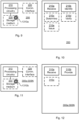
- Fig. 9 schematically illustrates, in terms of a number of functional units, the components of an analyser device 200 according to an embodiment.
- Processing circuitry 210 is provided using any combination of one or more of a suitable central processing unit (CPU), multiprocessor, microcontroller, digital signal processor (DSP), etc., capable of executing software instructions stored in a computer program product 1310a (as in Fig. 13 ), e.g. in the form of a storage medium 230.
- the processing circuitry 210 may further be provided as at least one application specific integrated circuit (ASIC), or field programmable gate array (FPGA).
- ASIC application specific integrated circuit
- FPGA field programmable gate array
- the processing circuitry 210 is configured to cause the analyser device 200 to perform a set of operations, or steps, as disclosed above.
- the storage medium 230 may store the set of operations
- the processing circuitry 210 may be configured to retrieve the set of operations from the storage medium 230 to cause the analyser device 200 to perform the set of operations.
- the set of operations may be provided as a set of executable instructions.
- the processing circuitry 210 is thereby arranged to execute methods as herein disclosed.
- the storage medium 230 may also comprise persistent storage, which, for example, can be any single one or combination of magnetic memory, optical memory, solid state memory or even remotely mounted memory.
- the analyser device 200 may further comprise a communications interface 220 for communications with other entities, node, functions, and devices in the communication network of Fig. 1 .
- the communications interface 220 may comprise one or more transmitters and receivers, comprising analogue and digital components.
- the processing circuitry 210 controls the general operation of the analyser device 200 e.g. by sending data and control signals to the communications interface 220 and the storage medium 230, by receiving data and reports from the communications interface 220, and by retrieving data and instructions from the storage medium 230.
- Other components, as well as the related functionality, of the analyser device 200 are omitted in order not to obscure the concepts presented herein.
- Fig. 10 schematically illustrates, in terms of a number of functional modules, the components of an analyser device 200 according to an embodiment.
- the analyser device 200 of Fig. 10 comprises a number of functional modules; a receive module 210a configured to perform step S102, and an identify module 210b configured to perform step S104.
- the analyser device 200 of Fig. 10 may further comprise a number of optional functional modules, such as any of a determine module 210C configured to perform step S106, a verify module 210d configured to perform step S108, and an issue module 210e configured to perform step S110.
- each functional module 210a-210e may be implemented in hardware or in software.
- one or more or all functional modules 210a-210e may be implemented by the processing circuitry 210, possibly in cooperation with the communications interface 220 and/or the storage medium 230.
- the processing circuitry 210 may thus be arranged to from the storage medium 230 fetch instructions as provided by a functional module 210a-210e and to execute these instructions, thereby performing any steps of the analyser device 200 as disclosed herein.
- the analyser device 200 may be provided as a standalone device or as a part of at least one further device.
- the analyser device 200 may be provided in a node of a radio access network or in a node of a core network.
- functionality of the analyser device 200 may be distributed between at least two devices, or nodes. These at least two nodes, or devices, may either be part of the same network part (such as the radio access network or the core network) or may be spread between at least two such network parts.
- instructions that are required to be performed in real time may be performed in a device, or node, operatively closer to the cell than instructions that are not required to be performed in real time.
- a first portion of the instructions performed by the analyser device 200 may be executed in a first device, and a second portion of the instructions performed by the analyser device 200 may be executed in a second device; the herein disclosed embodiments are not limited to any particular number of devices on which the instructions performed by the analyser device 200 may be executed.
- the methods according to the herein disclosed embodiments are suitable to be performed by an analyser device 200 residing in a cloud computational environment. Therefore, although a single processing circuitry 210 is illustrated in Fig. 9 the processing circuitry 210 may be distributed among a plurality of devices, or nodes. The same applies to the functional modules 210a-210e of Fig. 10 and the computer program 1320a of Fig. 13 .
- Fig. 11 schematically illustrates, in terms of a number of functional units, the components of a radio device 300a:300N
- Processing circuitry 310 is provided using any combination of one or more of a suitable central processing unit (CPU), multiprocessor, microcontroller, digital signal processor (DSP), etc., capable of executing software instructions stored in a computer program product 1310b (as in Fig. 13 ), e.g. in the form of a storage medium 330.
- the processing circuitry 310 may further be provided as at least one application specific integrated circuit (ASIC), or field programmable gate array (FPGA).
- ASIC application specific integrated circuit
- FPGA field programmable gate array
- the processing circuitry 310 is configured to cause the radio device 300a:300N to perform a set of operations, or steps, as disclosed above.
- the storage medium 330 may store the set of operations
- the processing circuitry 310 may be configured to retrieve the set of operations from the storage medium 330 to cause the radio device 300a:300N to perform the set of operations.
- the set of operations may be provided as a set of executable instructions.
- the processing circuitry 310 is thereby arranged to execute methods as herein disclosed.
- the storage medium 330 may also comprise persistent storage, which, for example, can be any single one or combination of magnetic memory, optical memory, solid state memory or even remotely mounted memory.
- the radio device 300a:300N may further comprise a communications interface 320 for communications with other entities, node, functions, and devices in the communication network of Fig. 1 .
- the communications interface 320 may comprise one or more transmitters and receivers, comprising analogue and digital components.
- the processing circuitry 310 controls the general operation of the radio device 300a:300N e.g. by sending data and control signals to the communications interface 320 and the storage medium 330, by receiving data and reports from the communications interface 320, and by retrieving data and instructions from the storage medium 330.
- Other components, as well as the related functionality, of the radio device 300a:300N are omitted in order not to obscure the concepts presented herein.
- Fig. 12 schematically illustrates, in terms of a number of functional modules, the components of a radio device 300a:300N
- the radio device 300a:300N of Fig. 12 comprises a number of functional modules; a receive module 310a configured to perform step S202, and a provide module 310b configured to perform step S204.
- the radio device 300a:300N of Fig. 12 may further comprise a number of optional functional modules, as represented by functional module 310c.
- each functional module 310a-310c may be implemented in hardware or in software.
- one or more or all functional modules 310a-310c may be implemented by the processing circuitry 310, possibly in cooperation with the communications interface 320 and/or the storage medium 330.
- the processing circuitry 310 may thus be arranged to from the storage medium 330 fetch instructions as provided by a functional module 310a-310c and to execute these instructions, thereby performing any steps of the radio device 300a:300N as disclosed herein.
- Fig. 13 shows one example of a computer program product 1310a, 1310b comprising computer readable means 1330.
- a computer program 1320a can be stored, which computer program 1320a can cause the processing circuitry 210 and thereto operatively coupled entities and devices, such as the communications interface 220 and the storage medium 230, to execute methods according to embodiments described herein.
- the computer program 1320a and/or computer program product 1310a may thus provide means for performing any steps of the analyser device 200 as herein disclosed.
- a computer program 1320b can be stored, which computer program 1320b can cause the processing circuitry 310 and thereto operatively coupled entities and devices, such as the communications interface 320 and the storage medium 330, to execute methods according to embodiments described herein.
- the computer program 1320b and/or computer program product 1310b may thus provide means for performing any steps of the radio device 300a:300N as herein disclosed.
- the computer program product 1310a, 1310b is illustrated as an optical disc, such as a CD (compact disc) or a DVD (digital versatile disc) or a Blu-Ray disc.
- the computer program product 1310a, 1310b could also be embodied as a memory, such as a random access memory (RAM), a read-only memory (ROM), an erasable programmable read-only memory (EPROM), or an electrically erasable programmable read-only memory (EEPROM) and more particularly as a non-volatile storage medium of a device in an external memory such as a USB (Universal Serial Bus) memory or a Flash memory, such as a compact Flash memory.
- RAM random access memory
- ROM read-only memory
- EPROM erasable programmable read-only memory
- EEPROM electrically erasable programmable read-only memory
- the computer program 1320a, 1320b is here schematically shown as a track on the depicted optical disk, the computer program 1320a,
Description
- Embodiments presented herein relate to identifying a fraudulent base station.
- Cellular telecommunication systems (2G systems, 3G systems, 4G systems, and 5G systems) are inherently built of a structure of interconnected cells, where a cell in this concept represents a coverage region served by a base station emitting wireless radio signals. Typically, base stations are equipped with powerful RF (Radio Frequency) transceivers and antennas in order to serve its coverage region. Cellular telecommunication systems are sometimes also referred as mobile communication systems (or networks), cellular (or wireless) communications networks, cellular radio systems or cellular networks. In these systems, several services might be offered, such as wireless Internet access, voice call service, short messaging services, and data sharing between users. Here, each user is represented by its a user equipment (UE) to access cellular telecommunication system.
- Base stations are referred with various terms in different generations of cellular telecommunication systems. For example, they are termed as base transceiver station (BTS) in 2G systems, NodeB in 3G systems, eNodeB in 4G systems and gNodeB in 5G systems. Base stations emit radio signals structured according to related international standards. These signals include, for example, information about the base station itself, such as physical cell ID, signal frequency, and synchronization information. Each UE extracts this information from the received signals and calculate various parameter values, such as RSRP (Reference Signal Received Power). RSRP depends on several factors, for example the radiating power of the base station, the receiver sensitivity at the UE, and the location at which the measurements are made. A UE might sense RF signals simultaneously belonging to different base stations and select the one which is believed to best serve the UE based on some standard criteria. One criteria in this regard is the RSRP, since UEs tend to attach a base station resulting in highest possible RSSP. This base station is generally the one physically closest to the UE.
- Each UE is associated with a subscriber, needed for the UE to gain access to the cellular telecommunication system via the base station. Subscribers in the cellular telecommunication systems have a long-term identifier, denoted International Mobile Subscriber Identifier (IMSI), which for example could be embedded in a Universal Subscriber Identity Module (USIM). This is a unique identifier assigned to the subscriber, and should therefore be handled with care in network protocols and applications for security and privacy reasons. When a subscriber attempts to join the network by connecting to a base station via the UE, an attach procedure is performed. The attach procedure requires disclosure over a radio link of the identity of the UE. At this step, a short-term identifier, denoted Temporary Mobile Subscriber Identity (TMSI), is used rather than IMSI to ensure privacy of the subscriber. TMSIs are generated by the core network and kept in a database, the Visitor Location Register (VLR), which relates TMSIs and corresponding IMSIs. The TMSI is updated regularly depending on the physical location of the UE.
- During the attach procedure in 4G systems (and in earlier generation systems), the UE is requested to identify itself by the mobility management entity (MME), or similar, through the base station the UE is attempting to connect to. The UE commonly respond to this request by declaring its TMSI. Yet, related standards allow base stations to request the long-term identifier, the IMSI, instead of the TMSI, by sending a special IDENTITY REQUEST message, as a mechanism to resolve cases where TMSIs are lost or unreachable in the network. This mechanism might be exploited by malicious unauthorized base stations, hereinafter denoted a fraudulent base station, to capture the IMSI of the UE by transmitting IDENTITY REQUEST messages. To do so, the fraudulent base station might advertise itself as a preferred service point for the UE by radiating more powerful signals than other base station.
- Fraudulent base stations as referred to in the present disclosure are sometimes referred to with different terms, such as fake base stations, IMSI catchers, stingrays, rogue base stations, false base stations, and the like. In the present disclosure the term fraudulent base station is used to denote a base station set up with the aim to capture the long-term identifier (such as the IMSI) of subscribers of UEs in a cellular telecommunication system.
- In some cases, a fraudulent base station might achieve its goal by exploiting the procedures of Tracking Area Update (TAU), as used in 4G systems, and Location Area Update (LAU), as used in 3G systems, in such a way that the fraudulent base station advertise itself with a different Tracking Area Identity or Location Area Identity from legitimate base stations, and thereby convince the UE receiving signals from the fraudulent base station to initiate a TAU or LAU procedure that involves an attach procedure. Because there is no required security mechanism by design for mutual authentication between a UE and a base station during the initial phase of the attach procedure, a fraudulent base station might thereby obtain the IMSI of the UE. Legal measures might not be sufficient to preventing this kind of misuse of base stations. Hence, it might also necessary be necessary to take some technical countermeasures.
- Earlier approaches proposed for detection of fraudulent base stations can be categorized into two groups: (i) Device-assisted mechanisms, and (ii) Network-assisted mechanisms. As an example of the first category, a technician might manually observe the radio signals received at a specific location by using a radio device or spectrum analyzer to see if there is any suspicious signal that could be a sign for a possible fraudulent base station. As another example of the first category, a special kind of terminal is configured to send a Location Area Update Request message to a targeted base station, and then if a REJECT message is received from this base station in return, it is identified as a fraudulent base station. As an example of the second category, regular measurement reports of all UEs in a region of interest are first collected by the base stations and forwarded to a central unit for further processing. Then, anomaly detection is performed at the central unit by analyzing the collected measurement reports whilst comparing to the network topology of all legitimate base stations.
- The above earlier approaches in the first category could be cumbersome to implement and the above earlier approaches in the second category could have high computational requirements. Hence, there is still a need for improved detection of fraudulent base stations.
-
WO 2016/206610 discloses user equipments (UEs) which report abnormalities to a server, when an unusual location update from a suspicious base station (BS) is detected. -
EP 2 661 113 discloses a system wherein a BS is detected as being rogue, when the BS requests rapid successive re-registrations from a mobile terminal (MT) to force the MT to reveal its identifiers, at a rate above a pre-determined time interval. - An object of embodiments herein is to provide efficient identification and reporting of fraudulent base stations not suffering from the issues noted above, or at least where the above issues are mitigated or reduced.
- According to a first aspect there is presented a system for identifying a fraudulent base station. The system comprises an analyser device and at least two radio devices. The system is configured to provide a report, from any of the at least two radio devices and to the analyser device upon that any of the at least two radio devices having received from a base station an identity request message for a long-term identifier of that any of the at least two radio devices, of the identity request message. The system is configured to identify, by the analyser device, the base station as fraudulent when reports of the same base station as received from at least two different ones of the at least two radio devices are received within a threshold time duration with respect to each other.
- According to a second aspect there is presented a method for identifying a fraudulent base station. The method is performed by an analyser device. The method comprises receiving a report, from any of at least two radio devices upon that any of the at least two radio devices having received from a base station an identity request message for a long-term identifier of that any of the at least two radio devices, of the identity request message. The method comprises identifying the base station as fraudulent when reports of the same base station as received from two different ones of the at least two radio devices are received within a threshold time duration with respect to each other.
- According to a third aspect there is presented an analyser device for identifying a fraudulent base station. The analyser device comprises processing circuitry. The processing circuitry is configured to cause the analyser device to receive a report, from any of at least two radio devices upon that any of the at least two radio devices having received from a base station an identity request message for a long-term identifier of that any of the at least two radio devices, of the identity request message. The processing circuitry is configured to cause the analyser device to identify the base station as fraudulent when reports of the same base station as received from two different ones of the at least two radio devices are received within a threshold time duration with respect to each other.
- According to a fourth aspect there is presented a computer program for identifying a fraudulent base station. The computer program comprises computer program code which, when run on processing circuitry of an analyser device, causes the analyser device to perform a method according to the second aspect.
- According to a fifth aspect there is presented a computer program product comprising a computer program according to the fourth aspect and a computer readable storage medium on which the computer program is stored. The computer readable storage medium could be a non-transitory computer readable storage medium.
- Advantageously this method, this system, this analyser device, this computer program and this computer program product provide efficient identification and reporting of fraudulent base stations.
- Advantageously this method, this system, this analyser device, this computer program and this computer program product do not suffer from the issues noted above.
- Advantageously this method, this system, this analyser device, this computer program and this computer program product are easy to implement and do not have high computational requirements.
- Advantageously this method, this system, this analyser device, this computer program and this computer program product enable instantaneous detection of fraudulent base stations without requiring any prior preparations, such as data collection related to legitimate network or region to be scanned.
- Advantageously this method, this system, this analyser device, this computer program and this computer program product do not require any change at the network level or protocols used.
- Advantageously this method, this system, this analyser device, this computer program and this computer program product enable false alarms to be decreased and the detection accuracy to be increased compared to training-based mechanisms for detecting fraudulent base stations.
- Advantageously this method, this system, this analyser device, this computer program and this computer program product do not require any private information about the network or about the end-users, thus eliminating the risk of privacy issue to occur.
- Other objectives, features and advantages of the enclosed embodiments will be apparent from the following detailed disclosure, from the attached dependent claims as well as from the drawings.
- Generally, all terms used in the claims are to be interpreted according to their ordinary meaning in the technical field, unless explicitly defined otherwise herein. All references to "a/an/the element, apparatus, component, means, module, step, etc." are to be interpreted openly as referring to at least one instance of the element, apparatus, component, means, module, step, etc., unless explicitly stated otherwise. The steps of any method disclosed herein do not have to be performed in the exact order disclosed, unless explicitly stated.
- The inventive concept is now described, by way of example, with reference to the accompanying drawings, in which:
-
Fig. 1 is a schematic diagram illustrating a cellular telecommunication system according to embodiments; -
Figs. 2 and 3 are schematic illustrations of a system according to embodiments; -
Figs. 4 ,5 ,6 , and7 are flowcharts of methods according to embodiments; -
Fig. 8 is a signalling diagram according to an embodiment; -
Fig. 9 is a schematic diagram showing functional units of an analyser device according to an embodiment; -
Fig. 10 is a schematic diagram showing functional modules of an analyser device according to an embodiment; -
Fig. 11 is a schematic diagram showing functional units of a radio device; -
Fig. 12 is a schematic diagram showing functional modules of a radio device; -
Fig. 13 shows one example of a computer program product comprising computer readable means according to an embodiment. - The inventive concept will now be described more fully hereinafter with reference to the accompanying drawings, in which certain embodiments of the inventive concept are shown. This inventive concept may, however, be embodied in many different forms and should not be construed as limited to the embodiments set forth herein; rather, these embodiments are provided by way of example so that this disclosure will be thorough and complete, and will fully convey the scope of the inventive concept to those skilled in the art. Like numbers refer to like elements throughout the description. Any step or feature illustrated by dashed lines should be regarded as optional.
-
Fig. 1 is a schematic diagram illustrating a simplification of acellular telecommunication system 10 where embodiments presented herein can be applied. Thecellular telecommunication system 10 comprises abase station 20, assumed to be a fraudulent base station. Thefraudulent base station 20 transmit radio signals, as indicated by radiatingarrows 30. It is assumed that the radio signals are received by radio devices (RD) 300a, 300b. As will be disclosed in more detail below, theradio devices analyser device 200 and at least tworadio devices system 100. - The embodiments disclosed herein in particular relate to mechanisms for identifying a
fraudulent base station 20 and reporting afraudulent base station 20. In order to obtain such mechanisms there is provided ananalyser device 200, a method performed by theanalyser device 200, a computer program product comprising code, for example in the form of a computer program, that when run on processing circuitry of theanalyser device 200, causes theanalyser device 200 to perform the method. In order to obtain such mechanisms there is further provided aradio device 300a:300N, a method performed by theradio device 300a:300N, and a computer program product comprising code, for example in the form of a computer program, that when run on processing circuitry of theradio device 300a:300N, causes theradio device 300a:300N to perform the method. In order to obtain such mechanisms there is further provided a system comprising theanalyser device 200 and at least tworadio devices 300a:300N. - There could be
different systems 100. Two non-limiting examples thereof will now be disclosed with reference toFig. 2 and Fig. 3 . -
Fig. 2 illustrates asystem 100 according to a first embodiment. In the embodiment ofFig. 2 , each of the at least tworadio devices 300a:300N is operatively connected to theanalyser device 200 over awired connection 40a. As the skilled person, there could be different types of wired connections, such as optical fiber connections, coaxial cable connections, twisted pair cable connections, and the like. In the embodiment ofFig. 2 , theanalyser device 200 and the at least tworadio devices 300a:300N are integrated, collocated, or provided, within one and the same physical entity, where this physical entity defines thesystem 100. Thesystem 100 ofFig. 2 might be stationary and fixed to a critical location to enable continuous monitoring of any fraudulent base stations at such a critical location. Hence, according to an example, thesystem 100 is configured to be mounted on a fixed location. Thesystem 100 ofFig. 2 might alternatively be mounted on a vehicle (e.g. car, unmanned aerial vehicle (UAV), or the like) to enable intermittently monitoring of different locations. Hence, according to an example, thesystem 100 is configured to be movable. In this sense, more than onesuch system 100 might be deployed to monitor different regions and configured to issue notifications of base stations deemed fraudulent. -
Fig. 3 illustrates asystem 100 according to a second embodiment. In the embodiment ofFig. 3 , each of the at least tworadio devices 300a:300N is operatively connected to theanalyser device 200 over awireless connection 40b. InFig. 3 is also illustrated further, optional, at least tworadio devices 300a':300N', each of which is operatively connected to theanalyser device 200 over a respective wireless connection. As the skilled person, there could be different types of wireless connections, such as wireless connections using radio signalling, wireless connections using infrared signalling, and the like. Theanalyser device 200 of thesystem 100 inFig. 3 might reside in a cloud computational environment. Thesystem 100 ofFig. 3 is by definition considered to be movable by the virtue of the at least tworadio devices 300a:300N being movable. - In some embodiments, such as in the first and second embodiments above, it is assumed that the at least two
radio devices 300a:300N are positioned relative each other to receive signals from the same base station. In the example ofFig. 2 ,radio devices 300a:300N form a first group of radio devices positioned relative each other to receive signals from one and the same base station andoptional radio devices 300a':300N' form a second group of radio devices positioned relative each other to receive signals from one and the same base station - Reference is now made to
Fig. 4 illustrating a method for identifying afraudulent base station 20 as performed by theanalyser device 200 according to an embodiment. - As will be further disclosed below, each of the
radio devices 300a:300N is configured to report any received identity request messages to theanalyser device 200. Hence, theanalyser device 200 is configured to perform S102:
S102: Theanalyser device 200 receives a report. The report is received from any of at least tworadio devices 300a:300N upon that any of the at least tworadio devices 300a:300N having received from abase station 20 an identity request message for a long-term identifier of that any of the at least tworadio devices 300a:300N. The report is of the identity request message. - The
base station 20 is identified as fraudulent based on the time difference between the reports. In particular, theanalyser device 200 is configured to perform S104:
S104: Theanalyser device 200 identifies thebase station 20 as fraudulent when reports of thesame base station 20 as received from two different ones of the at least tworadio devices 300a:300N are received within a threshold time duration with respect to each other. - In this respect, from real network statistics follows that it is very unlikely that two or
more radio devices 300a:300N in proximity of each other receive simultaneously, or within very short period of time as defined by the threshold time duration, receive an identity request message. This is because of the fact that an identity request message is by a legitimate base station only sent to request the long-term identifier from a UE under some exceptional circumstances, such as at initial registration to network, when the long-term identifier is lost in the core network, or upon authentication failure between UEs and the base station. This fact is exploited by the herein disclosed embodiments. Hence, by means of theradio devices 300a:300N the radio environment can be efficiently (either continuously or intermittently) scanned for potential fraudulent base stations, enabling real-time detection and identification of any fraudulent base station. - Embodiments relating to further details of identifying a
fraudulent base station 20 as performed by theanalyser device 200 will now be disclosed. - In some aspects, the
analyser 200 issues a notification when thebase station 20 has been identified as fraudulent. In particular, in some embodiments theanalyser device 200 is configured to perform (optional) step S110:
S110: Theanalyser device 200 issues a notification of the thus identifiedfraudulent base station 20. - There could be different types of notification issued by the
analyser device 200 in S110. For example, the notification might be an alert message. There could be different types of recipients of the notification. For example, the notification might by theanalyser device 200 be sent to a network management entity. Thereby, when a fraudulent base station has been identified in S104, a notification in the form of an alert message might be sent by theanalyzer device 200 to a network management entity for further handling of the fraudulent base station. - In some aspects, the
analyser device 200 only issues the notification in S110 only if one or more conditions is satisfied. Examples of such conditions will be disclosed next. - One first condition relates to from how
many radio devices 300a:300N reports have been received within the threshold time duration. That is, in some embodiments, the notification is in S110 only issued when theanalyser device 200 has, for one and thesame base station 20, received reports separated from each other at most by the threshold time duration from at leastk radio devices 300a:300N, where k>1 is an integer. The higher the value of k, the higher the level of confidence that thebase station 20 indeed is fraudulent. - A certainty level can thereby be developed based on how
many radio devices 300a:300N are reporting identity request message for a long-term identifier at the same time, or within a time interval given by the threshold time duration. Alternatively, assuming that there are N radio devices in total that are configured to provide reports to theanalyser device 200, the notification might be issued when k devices out of N receive the same identity request message for a long-term identifier at the same time from the same cell. - One second condition relates to a certainty level for identifying the
base station 20 indeed as fraudulent. That is, in some embodiments theanalyser device 200 is configured to perform (optional) step S106:
S106: Theanalyser device 200 determines a certainty level based on how many reports separated from each other at most by the threshold time duration have been received and how many at least tworadio devices 300a:300N are operatively connected to theanalyser device 200. - The notification might then in S110 only be issued when the certainty level is above a certainty threshold value.
- One third condition relates to network statistics. In particular, in some embodiments, the certainty level further is based on network statistics obtained by the
analyser device 200. - One fourth condition relates to verification performed by the
analyser device 200. In general terms, a fraudulent base station will send identity request messages for the long-term identifier of theradio devices 300a:300N much more often than a legitimate base station, regardless of if theradio devices 300a:300N have valid long-term identifiers or not. According to real network statistics, for a legitimate base station, an identity request message for a long-term identifier could amount to less than 15% with respect to all identity request messages sent; for the remaining more than 85% the identity request message is for a short-term identifier. In particular, in some embodiments theanalyser device 200 is configured to perform (optional) step S108:
S108: Theanalyser device 200 verifies, by querying a database and before the notification is issued, that thebase station 20 is not a registered base station. - When S108 is performed, S108 is performed before S110 is performed.
- The
analyser device 200 might thus be configured to perform analyses on reports, if any, received from theradio devices 300a:300N and therefrom determine if there is any base station that should be considered as fraudulent based on the number of reports, content of the reports, and timestamps of the reports. - The herein disclosed
system 100 is flexible in the sense that parameters relating to any of the above four conditions might be set with regards to the sensitivity of the detection, for example by changing the value of the threshold time duration and also by adjusting from howmany radio devices 300a:300N reports need to be received for a notification to be issued. - Aspects of the report received from one or more of the
radio devices 300a:300N will now be disclosed. In some examples the at least oneradio device 300a:300N reports Cell ID, an identifier which unambiguously identifies a cell within a public land mobile network (PLMN). That is, in some embodiments, the report comprises a Cell ID of thebase station 20 having sent the identity request message. - There could be different examples of the long-term identifier. According to some embodiments, the long-term identifier is the IMSI.
- In some aspects, one or more of the at least two
radio devices 300a:300N is/are configured to be served by two or more mobile network operators. - Particularly, in some embodiments, the at least two
radio devices 300a:300N collectively are configured to be served by at least two different mobile network operators. Thereby, one and thesame system 100 might be used to identify fraudulent base stations for two or more mobile network operators, which in turn might lower costs and overall power consumption to detect fraudulent base stations in a specific region for all the mobile network operators. - However, this does not necessarily imply that signals from base stations operated by two or more mobile network operators are simultaneously collected and analysed.
- Aspects of when the identity request message is transmitted by the
base station 200 and thus received by the at least tworadio devices 300a:300N will now be disclosed. According to a first example, the identity request message is received during an attach procedure, a TAU procedure, or a LAU procedure. According to a second example, the identity request message is received without said any of the at least tworadio devices 300a:300N having experienced network lock out. According to a third example, the identity request message is received upon said any of the at least tworadio devices 300a:300N already having performed initial registration since its radio modem lastly was switched on. - Reference is now made to
Fig. 5 illustrating a method for reporting afraudulent base station 20 as performed by theradio device 300a:300N according to an embodiment. - The
radio device 300a:300N is configured to receive messages from base stations. In particular, theradio device 300a:300N is configured to perform S202:
S202: Theradio device 300a:300N receives, from abase station 20, an identity request message for a long-term identifier of theradio device 300a:300N. - The
radio device 300a:300N then reports this identity request message to the analyser device. That is, theradio device 300a:300N is configured to perform S204:
S204: Theradio device 300a:300N provides a report of the identity request message to ananalyser device 200 upon theradio device 300a:300N having received the identity request message. - Embodiments relating to further details of reporting a
fraudulent base station 20 as performed by theradio device 300a:300N will now be disclosed. - In general terms, the
radio device 300a:300N is registered to the network as an ordinary UE. - As above, in some embodiments, the report comprises a Cell ID of the
base station 20 having sent the identity request message. - As above, in some embodiments, the long-term identifier is the IMSI.
- As above, according to a first example, the identity request message is by the
radio device 300a:300N received during an attach procedure, a TAU procedure, or a LAU procedure. As above, according to a second example, the identity request message is received without theradio device 300a:300N having experienced network lock out. As above, according to a third example, the identity request message is received upon theradio device 300a:300N already having performed initial registration since its radio modem lastly was switched on. - Reference is made to the flowchart of
Fig. 6 illustrating a method for reporting afraudulent base station 20 as performed by theradio device 300a:300N based on at least some of the above embodiments. - S301: The
radio device 300a:300N listens for any messages as transmitted from base stations. - S302: The
radio device 300a:300N receives a message from one of the base stations. - S303: The
radio device 300a:300N checks if the message is an identity request message for a long-term identifier. If yes, then step S304 is entered, and if no, then step S301 is entered. - S304: The
radio device 300a:300N reports the message to theanalyser device 200. - Reference is made to
Fig. 7 illustrating a method for identifying afraudulent base station 20 as performed by theanalyser device 200 based on at least some of the above embodiments. - S401: The
analyser device 200 listens for any reports of identity request messages for a long-term identifier having being received by any of theradio devices 300a:300N. - S402: The
analyser device 200 receives, from one of theradio devices 300a:300N, a report of an identity request message for a long-term identifier having been received by this one of theradio devices 300a:300N. - S403: The
analyser device 200 writes the received report and a timestamp indicating when in time the report was received to a list. Alternatively, the timestamp indicates when in time the identity request message was received by therelated radio device 300a:300N. - S404: The
analyser device 200 removes from the list any report with timestamp older than a threshold time value. Theanalyser device 200 also removes from the list any previous report of the same base station from thesame radio device 300a:300N even if this previous report is not older than the threshold time value. - S405: The
analyser device 200 checks if there are more than k reports in the list. If yes, then step S406 is entered, and if no, then step S401 is entered. - S406: The
analyser device 200 issues a notification of a fraudulent base station having been identified. - Reference is made to
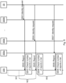
Fig. 8 illustrating a method for identifying and reporting afraudulent base station 20 as performed by theanalyser device 200 andradio devices 300a:300N based on at least some of the above embodiments. - S501:
Fraudulent base station 20 sends an identity request message for a long-term identifier. The identity request message is received byradio device 300N. - S502:
Radio device 300N provides a report of the identity request message toanalyser device 200 and also attaches its own ID, and optionally a timestamp indicating when the identity request message was received, to the report. - S503:
Analyser device 200 writes the received report and a timestamp indicating when the report was received (and/or when in time the identity request message was received by therelated radio device 300a:300N) to a list.Analyser device 200 removes from the list any previous report received fromradio device 300N pertaining to the same reported base station. Since no previous reports have been received, no reports are removed. Theanalyser device 200 checks if there, for the same base station, are k>1 reports in the list and if these k reports all have timestamp not older than the threshold time value given by the time window W1. Since only one report has been received, this condition is not fulfilled.Base station 20 is therefore not yet identified as fraudulent. - S504:
Fraudulent base station 20 sends another identity request message for a long-term identifier. The identity request message is received byradio device 300b. - S505:
Radio device 300b provides a report of the identity request message toanalyser device 200 and also attaches its own ID, and optionally a timestamp indicating when the identity request message was received, to the report. - S506:
Analyser device 200 writes the received report and a timestamp indicating when the report was received (and/or when in time the identity request message was received by therelated radio device 300a:300N) to the list. Theanalyser device 200 removes from the list any previous report received fromradio device 300b. Since no previous reports have been received fromradio device 300b, no reports are removed. Theanalyser device 200 checks if there, for the same base station, are k>1 reports and if these k reports all have timestamp not older than the threshold time value given by the time window W2. Since there are two reports for one and the same base station in the list (i.e., k=2) and these reports were both received within the time window W2, this condition is fulfilled.Base station 20 is therefore identified as fraudulent. A notification might therefore be issued by theanalyser device 200. - S507:
Fraudulent base station 20 sends yet another identity request message for a long-term identifier. The identity request message is received byradio device 300a. - S508:
Radio device 300a provides a report of the identity request message toanalyser device 200 and also attaches its own ID, and optionally a timestamp indicating when the identity request message was received, to the report. - S506:
Analyser device 200 writes the received report and a timestamp indicating when the report was received (and/or when in time the identity request message was received by therelated radio device 300a:300N) to the list.Analyser device 200 removes from the list any previous report received fromradio device 300a. Since no previous reports have been received fromradio device 300a, no reports are removed. Theanalyser device 200 checks if there are more than k>1 reports and if these k reports all have timestamp not older than the threshold time value given by the time window W3. There are now three reports in the list, but the reports fromradio device 300b andradio device 300N were both received outside the time window W3, this condition is no longer fulfilled.Base station 20 is therefore in this context not identified as fraudulent. - In this
embodiment analyser device 200 thus in a list keeps only the most recent report received for eachradio device 300a:300N. Also, older reports are regularly removed from the list according to a sliding time window (as given by W1, W2, W3). In this respect, W1, W2, and W3 are thus examples of the threshold time duration. Whenever there are k>1 reports in the list, this is an indication that a fraudulent base station has been identified. - Although the condition that there are k>1 reports in the list has been used in some of the embodiments and examples above, there could also be other conditions. For example, a general condition is that it could be required that there are k>z reports in the list, where z>1. The higher the value of z, the higher the chance that the
base station 20 indeed is fraudulent. However, increasing the value of z also increases the risk of missing to identify abase station 20 as fraudulent. In general terms, the value of z could be set so as to be dependent on the total number N ofradio devices 300a:300N; the higher the value of N, the higher is the value that z could be set to. Of course, z should never be set to a value higher than N. -
Fig. 9 schematically illustrates, in terms of a number of functional units, the components of ananalyser device 200 according to an embodiment.Processing circuitry 210 is provided using any combination of one or more of a suitable central processing unit (CPU), multiprocessor, microcontroller, digital signal processor (DSP), etc., capable of executing software instructions stored in acomputer program product 1310a (as inFig. 13 ), e.g. in the form of astorage medium 230. Theprocessing circuitry 210 may further be provided as at least one application specific integrated circuit (ASIC), or field programmable gate array (FPGA). - Particularly, the
processing circuitry 210 is configured to cause theanalyser device 200 to perform a set of operations, or steps, as disclosed above. For example, thestorage medium 230 may store the set of operations, and theprocessing circuitry 210 may be configured to retrieve the set of operations from thestorage medium 230 to cause theanalyser device 200 to perform the set of operations. The set of operations may be provided as a set of executable instructions. Thus theprocessing circuitry 210 is thereby arranged to execute methods as herein disclosed. - The
storage medium 230 may also comprise persistent storage, which, for example, can be any single one or combination of magnetic memory, optical memory, solid state memory or even remotely mounted memory. - The
analyser device 200 may further comprise acommunications interface 220 for communications with other entities, node, functions, and devices in the communication network ofFig. 1 . As such thecommunications interface 220 may comprise one or more transmitters and receivers, comprising analogue and digital components. - The
processing circuitry 210 controls the general operation of theanalyser device 200 e.g. by sending data and control signals to thecommunications interface 220 and thestorage medium 230, by receiving data and reports from thecommunications interface 220, and by retrieving data and instructions from thestorage medium 230. Other components, as well as the related functionality, of theanalyser device 200 are omitted in order not to obscure the concepts presented herein. -
Fig. 10 schematically illustrates, in terms of a number of functional modules, the components of ananalyser device 200 according to an embodiment. Theanalyser device 200 ofFig. 10 comprises a number of functional modules; a receivemodule 210a configured to perform step S102, and anidentify module 210b configured to perform step S104. Theanalyser device 200 ofFig. 10 may further comprise a number of optional functional modules, such as any of a determine module 210C configured to perform step S106, a verifymodule 210d configured to perform step S108, and anissue module 210e configured to perform step S110. In general terms, eachfunctional module 210a-210e may be implemented in hardware or in software. Preferably, one or more or allfunctional modules 210a-210e may be implemented by theprocessing circuitry 210, possibly in cooperation with thecommunications interface 220 and/or thestorage medium 230. Theprocessing circuitry 210 may thus be arranged to from thestorage medium 230 fetch instructions as provided by afunctional module 210a-210e and to execute these instructions, thereby performing any steps of theanalyser device 200 as disclosed herein. - The
analyser device 200 may be provided as a standalone device or as a part of at least one further device. For example, theanalyser device 200 may be provided in a node of a radio access network or in a node of a core network. Alternatively, functionality of theanalyser device 200 may be distributed between at least two devices, or nodes. These at least two nodes, or devices, may either be part of the same network part (such as the radio access network or the core network) or may be spread between at least two such network parts. In general terms, instructions that are required to be performed in real time may be performed in a device, or node, operatively closer to the cell than instructions that are not required to be performed in real time. Thus, a first portion of the instructions performed by theanalyser device 200 may be executed in a first device, and a second portion of the instructions performed by theanalyser device 200 may be executed in a second device; the herein disclosed embodiments are not limited to any particular number of devices on which the instructions performed by theanalyser device 200 may be executed. Hence, the methods according to the herein disclosed embodiments are suitable to be performed by ananalyser device 200 residing in a cloud computational environment. Therefore, although asingle processing circuitry 210 is illustrated inFig. 9 theprocessing circuitry 210 may be distributed among a plurality of devices, or nodes. The same applies to thefunctional modules 210a-210e ofFig. 10 and thecomputer program 1320a ofFig. 13 . -
Fig. 11 schematically illustrates, in terms of a number of functional units, the components of aradio device 300a:300N Processing circuitry 310 is provided using any combination of one or more of a suitable central processing unit (CPU), multiprocessor, microcontroller, digital signal processor (DSP), etc., capable of executing software instructions stored in acomputer program product 1310b (as inFig. 13 ), e.g. in the form of astorage medium 330. Theprocessing circuitry 310 may further be provided as at least one application specific integrated circuit (ASIC), or field programmable gate array (FPGA). - Particularly, the
processing circuitry 310 is configured to cause theradio device 300a:300N to perform a set of operations, or steps, as disclosed above. For example, thestorage medium 330 may store the set of operations, and theprocessing circuitry 310 may be configured to retrieve the set of operations from thestorage medium 330 to cause theradio device 300a:300N to perform the set of operations. The set of operations may be provided as a set of executable instructions. Thus theprocessing circuitry 310 is thereby arranged to execute methods as herein disclosed. - The
storage medium 330 may also comprise persistent storage, which, for example, can be any single one or combination of magnetic memory, optical memory, solid state memory or even remotely mounted memory. - The
radio device 300a:300N may further comprise acommunications interface 320 for communications with other entities, node, functions, and devices in the communication network ofFig. 1 . As such thecommunications interface 320 may comprise one or more transmitters and receivers, comprising analogue and digital components. - The
processing circuitry 310 controls the general operation of theradio device 300a:300N e.g. by sending data and control signals to thecommunications interface 320 and thestorage medium 330, by receiving data and reports from thecommunications interface 320, and by retrieving data and instructions from thestorage medium 330. Other components, as well as the related functionality, of theradio device 300a:300N are omitted in order not to obscure the concepts presented herein. -
Fig. 12 schematically illustrates, in terms of a number of functional modules, the components of aradio device 300a:300N Theradio device 300a:300N ofFig. 12 comprises a number of functional modules; a receivemodule 310a configured to perform step S202, and a providemodule 310b configured to perform step S204. Theradio device 300a:300N ofFig. 12 may further comprise a number of optional functional modules, as represented byfunctional module 310c. In general terms, eachfunctional module 310a-310c may be implemented in hardware or in software. Preferably, one or more or allfunctional modules 310a-310c may be implemented by theprocessing circuitry 310, possibly in cooperation with thecommunications interface 320 and/or thestorage medium 330. Theprocessing circuitry 310 may thus be arranged to from thestorage medium 330 fetch instructions as provided by afunctional module 310a-310c and to execute these instructions, thereby performing any steps of theradio device 300a:300N as disclosed herein. -
Fig. 13 shows one example of acomputer program product readable means 1330. On this computerreadable means 1330, acomputer program 1320a can be stored, whichcomputer program 1320a can cause theprocessing circuitry 210 and thereto operatively coupled entities and devices, such as thecommunications interface 220 and thestorage medium 230, to execute methods according to embodiments described herein. Thecomputer program 1320a and/orcomputer program product 1310a may thus provide means for performing any steps of theanalyser device 200 as herein disclosed. On this computerreadable means 1330, acomputer program 1320b can be stored, whichcomputer program 1320b can cause theprocessing circuitry 310 and thereto operatively coupled entities and devices, such as thecommunications interface 320 and thestorage medium 330, to execute methods according to embodiments described herein. Thecomputer program 1320b and/orcomputer program product 1310b may thus provide means for performing any steps of theradio device 300a:300N as herein disclosed. - In the example of
Fig. 1-3 , thecomputer program product computer program product computer program computer program computer program product - The inventive concept has mainly been described above with reference to a few embodiments. However, as is readily appreciated by a person skilled in the art, other embodiments than the ones disclosed above are equally possible within the scope of the inventive concept, as defined by the appended patent claims.
Claims (19)
- A system (100) for identifying a fraudulent base station (20), the system (100) comprising an analyser device (200) and at least two radio devices (300a:300N), configured to:provide a report, from any of the at least two radio devices (300a:300N) and to the analyser device (200) upon said any of the at least two radio devices (300a:300N) having received from a base station (20) an identity request message for a long-term identifier of said any of the at least two radio devices (300a:300N), of the identity request message; andidentify, by the analyser device (200), the base station (20) as fraudulent when reports of the same base station (20) as received from at least two different ones of the at least two radio devices (300a:300N) are received within a threshold time duration with respect to each other.
- The system (100) according to claim 1, further being configured to:
issue, by the analyser device (200), a notification of the thus identified fraudulent base station (20). - The system (100) according to claim 2, wherein the notification only is issued when the analyser device (200) has received, from at least k radio devices (300a:300N), where k>1 is an integer, reports separated from each other at most by the threshold time duration.
- The system (100) according to any of the preceding claims, further being configured to:
determine, by the analyser device (200), a certainty level based on how many reports separated from each other at most by the threshold time duration have been received and how many at least two radio devices (300a:300N) are operatively connected to the analyser device (200). - The system (100) according to claim 5, wherein the notification only is issued when the certainty level is above a certainty threshold value.
- The system (100) according to claim 4 or 5, wherein the certainty level further is based on network statistics obtained by the analyser device (200).
- The system (100) according to any of the preceding claims, further being configured to:
verify, by the analyser device (200) querying a database and before the notification is issued, that the base station (20) is not a registered base station. - The system (100) according to any of the preceding claims, wherein the at least two radio devices (300a:300N) are positioned relative each other to receive signals from same base station.
- The system (100) according to any of the preceding claims, wherein the report comprises a Cell ID of the base station (20) having sent the identity request message.
- The system (100) according to any of the preceding claims, wherein the long-term identifier is an international mobile subscriber identity, IMSI.
- The system (100) according to any of the preceding claims, wherein the at least two radio devices (300a:300N) collectively are configured to be served by at least two different mobile network operators.
- The system (100) according to any of the preceding claims, wherein the identity request message is received during an attach procedure, a TAU procedure, or a LAU procedure.
- The system (100) according to any of the preceding claims, wherein the identity request message is received without said any of the at least two radio devices (300a:300N) having experienced network lock out.
- The system (100) according to any of the preceding claims, wherein the identity request message is received upon said any of the at least two radio devices (300a:300N) already having performed initial registration since its radio modem lastly was switched on.
- The system (100) according to any of claims 1 to 14, wherein the analyser device (200) and the at least two radio devices (300a:300N) are integrated, collocated, or provided, within one and the same physical entity defining the system (100).
- An analyser device (200) for identifying a fraudulent base station (20), the analyser device (200) comprising processing circuitry, the processing circuitry being configured to cause the analyser device (200) to:receive a report, from any of at least two radio devices (300a:300N) upon said any of the at least two radio devices (300a:300N) having received from a base station (20) an identity request message for a long-term identifier of said any of the at least two radio devices (300a:300N), of the identity request message; andidentify the base station (20) as fraudulent when reports of the same base station (20) as received from two different ones of the at least two radio devices (300a:300N) are received within a threshold time duration with respect to each other.
- A method for identifying a fraudulent base station (20), the method being performed by an analyser device (200), the method comprising:receiving (S102) a report, from any of at least two radio devices (300a:300N) upon said any of the at least two radio devices (300a:300N) having received from a base station (20) an identity request message for a long-term identifier of said any of the at least two radio devices (300a:300N), of the identity request message; andidentifying (S104) the base station (20) as fraudulent when reports of the same base station (20) as received from two different ones of the at least two radio devices (300a:300N) are received within a threshold time duration with respect to each other.
- A computer program (1320a) for identifying a fraudulent base station (20), the computer program comprising computer code which, when run on processing circuitry (210) of an analyser device (200), causes the analyser device (200) to:receive (S102) a report, from any of at least two radio devices (300a:300N) upon said any of the at least two radio devices (300a:300N) having received from a base station (20) an identity request message for a long-term identifier of said any of the at least two radio devices (300a:300N), of the identity request message; andidentify (S104) the base station (20) as fraudulent when reports of the same base station (20) as received from two different ones of the at least two radio devices (300a:300N) are received within a threshold time duration with respect to each other.
- A computer program product (1310a, 1310b) comprising a computer program (1320a, 1320b) according to claim 18, and a computer readable storage medium (1330) on which the computer program is stored.
Applications Claiming Priority (2)
| Application Number | Priority Date | Filing Date | Title |
|---|---|---|---|
| EP19404005 | 2019-09-24 | ||
| PCT/EP2019/079217 WO2021058120A1 (en) | 2019-09-24 | 2019-10-25 | Identyifying and reporting a fraudelent base station |
Publications (3)
| Publication Number | Publication Date |
|---|---|
| EP4035443A1 EP4035443A1 (en) | 2022-08-03 |
| EP4035443C0 EP4035443C0 (en) | 2023-10-25 |
| EP4035443B1 true EP4035443B1 (en) | 2023-10-25 |
Family
ID=68426423
Family Applications (1)
| Application Number | Title | Priority Date | Filing Date |
|---|---|---|---|
| EP19797617.8A Active EP4035443B1 (en) | 2019-09-24 | 2019-10-25 | Identyifying and reporting a fraudelent base station |
Country Status (5)
| Country | Link |
|---|---|
| US (1) | US20220345892A1 (en) |
| EP (1) | EP4035443B1 (en) |
| JP (1) | JP7403637B2 (en) |
| CN (1) | CN114424606A (en) |
| WO (1) | WO2021058120A1 (en) |
Families Citing this family (1)
| Publication number | Priority date | Publication date | Assignee | Title |
|---|---|---|---|---|
| EP4335137A1 (en) * | 2021-05-04 | 2024-03-13 | Telefonaktiebolaget LM Ericsson (publ) | Detection of false base stations |
Family Cites Families (6)
| Publication number | Priority date | Publication date | Assignee | Title |
|---|---|---|---|---|
| US8019333B2 (en) | 2005-03-14 | 2011-09-13 | Qualcomm Incorporated | Apparatus and methods for product acceptance testing on a wireless device |
| US8655312B2 (en) | 2011-08-12 | 2014-02-18 | F-Secure Corporation | Wireless access point detection |
| IL219500A (en) * | 2012-04-30 | 2017-06-29 | Verint Systems Ltd | Systems and methods for identifying rogue base stations |
| US9867039B2 (en) * | 2015-06-26 | 2018-01-09 | Futurewei Technologies, Inc. | System and method for faked base station detection |
| US9628994B1 (en) * | 2015-12-30 | 2017-04-18 | Argela Yazilim ve Bilisim Teknolojileri San. ve Tic. A.S. | Statistical system and method for catching a man-in-the-middle attack in 3G networks |
| WO2018014937A1 (en) * | 2016-07-19 | 2018-01-25 | Telefonaktiebolaget Lm Ericsson (Publ) | Node and method for detecting that a wireless device has been communicating with a non-legitimate device |
-
2019
- 2019-10-25 US US17/762,410 patent/US20220345892A1/en active Pending
- 2019-10-25 CN CN201980100585.5A patent/CN114424606A/en active Pending
- 2019-10-25 WO PCT/EP2019/079217 patent/WO2021058120A1/en active Search and Examination
- 2019-10-25 EP EP19797617.8A patent/EP4035443B1/en active Active
- 2019-10-25 JP JP2022515933A patent/JP7403637B2/en active Active
Also Published As
| Publication number | Publication date |
|---|---|
| EP4035443C0 (en) | 2023-10-25 |
| CN114424606A (en) | 2022-04-29 |
| JP7403637B2 (en) | 2023-12-22 |
| US20220345892A1 (en) | 2022-10-27 |
| EP4035443A1 (en) | 2022-08-03 |
| JP2022548847A (en) | 2022-11-22 |
| WO2021058120A1 (en) | 2021-04-01 |
Similar Documents
| Publication | Publication Date | Title |
|---|---|---|
| US10117094B2 (en) | Systems and methods for identifying rogue base stations | |
| CN107683617B (en) | System and method for pseudo base station detection | |
| US10200869B2 (en) | Network node and method for detecting false base stations | |
| US10904765B2 (en) | Method for operating a wireless communication device | |
| CN1972520B (en) | Rogue access point detection in wireless networks | |
| EP3488577B1 (en) | Node and method for detecting that a wireless device has been communicating with a non-legitimate device | |
| CN110868712B (en) | Terminal equipment identification method and communication device | |
| US8983527B2 (en) | Radio communication system, radio base station, and method for reconfiguring communication parameter | |
| EP4035443B1 (en) | Identyifying and reporting a fraudelent base station | |
| US11653241B2 (en) | Reporting performance degradation in a communications system | |
| CA2389189C (en) | Detecting a fraudulent mobile station in a mobile communication system using location information of mobile station | |
| US9326098B1 (en) | Identifying suspects and witness to shooting based on examination of calls made after shooting | |
| CN113347634B (en) | 4G and 5G air interface attack detection method based on signal and signaling fingerprint | |
| WO2020228948A1 (en) | Reporting of network performance degradation in a communications system | |
| KR20180082678A (en) | Method for detecting confusion of physical cell identity in mobile communication system |
Legal Events
| Date | Code | Title | Description |
|---|---|---|---|
| STAA | Information on the status of an ep patent application or granted ep patent |
Free format text: STATUS: UNKNOWN |
|
| STAA | Information on the status of an ep patent application or granted ep patent |
Free format text: STATUS: THE INTERNATIONAL PUBLICATION HAS BEEN MADE |
|
| PUAI | Public reference made under article 153(3) epc to a published international application that has entered the european phase |
Free format text: ORIGINAL CODE: 0009012 |
|
| STAA | Information on the status of an ep patent application or granted ep patent |
Free format text: STATUS: REQUEST FOR EXAMINATION WAS MADE |
|
| 17P | Request for examination filed |
Effective date: 20220407 |
|
| AK | Designated contracting states |
Kind code of ref document: A1 Designated state(s): AL AT BE BG CH CY CZ DE DK EE ES FI FR GB GR HR HU IE IS IT LI LT LU LV MC MK MT NL NO PL PT RO RS SE SI SK SM TR |
|
| DAV | Request for validation of the european patent (deleted) | ||
| DAX | Request for extension of the european patent (deleted) | ||
| REG | Reference to a national code |
Ref document number: 602019040178 Country of ref document: DE Ref country code: DE Ref legal event code: R079 Free format text: PREVIOUS MAIN CLASS: H04W0012120000 Ipc: H04W0012122000 |
|
| RIC1 | Information provided on ipc code assigned before grant |
Ipc: H04W 60/00 20090101ALN20230622BHEP Ipc: H04W 12/122 20210101AFI20230622BHEP |
|
| GRAP | Despatch of communication of intention to grant a patent |
Free format text: ORIGINAL CODE: EPIDOSNIGR1 |
|
| STAA | Information on the status of an ep patent application or granted ep patent |
Free format text: STATUS: GRANT OF PATENT IS INTENDED |
|
| INTG | Intention to grant announced |
Effective date: 20230728 |
|
| GRAS | Grant fee paid |
Free format text: ORIGINAL CODE: EPIDOSNIGR3 |
|
| GRAA | (expected) grant |
Free format text: ORIGINAL CODE: 0009210 |
|
| STAA | Information on the status of an ep patent application or granted ep patent |
Free format text: STATUS: THE PATENT HAS BEEN GRANTED |
|
| AK | Designated contracting states |
Kind code of ref document: B1 Designated state(s): AL AT BE BG CH CY CZ DE DK EE ES FI FR GB GR HR HU IE IS IT LI LT LU LV MC MK MT NL NO PL PT RO RS SE SI SK SM TR |
|
| REG | Reference to a national code |
Ref country code: GB Ref legal event code: FG4D |
|
| REG | Reference to a national code |
Ref country code: CH Ref legal event code: EP |
|
| REG | Reference to a national code |
Ref country code: DE Ref legal event code: R096 Ref document number: 602019040178 Country of ref document: DE |
|
| REG | Reference to a national code |
Ref country code: IE Ref legal event code: FG4D |
|
| U01 | Request for unitary effect filed |
Effective date: 20231025 |
|
| U07 | Unitary effect registered |
Designated state(s): AT BE BG DE DK EE FI FR IT LT LU LV MT NL PT SE SI Effective date: 20231030 |
|
| U20 | Renewal fee paid [unitary effect] |
Year of fee payment: 5 Effective date: 20231027 |
|
| PG25 | Lapsed in a contracting state [announced via postgrant information from national office to epo] |
Ref country code: GR Free format text: LAPSE BECAUSE OF FAILURE TO SUBMIT A TRANSLATION OF THE DESCRIPTION OR TO PAY THE FEE WITHIN THE PRESCRIBED TIME-LIMIT Effective date: 20240126 |
|
| PG25 | Lapsed in a contracting state [announced via postgrant information from national office to epo] |
Ref country code: IS Free format text: LAPSE BECAUSE OF FAILURE TO SUBMIT A TRANSLATION OF THE DESCRIPTION OR TO PAY THE FEE WITHIN THE PRESCRIBED TIME-LIMIT Effective date: 20240225 |