EP4034894B1 - Vorrichtung zur erkennung von räumlichen veränderungen der polarisation elektromagnetischer strahlung - Google Patents
Vorrichtung zur erkennung von räumlichen veränderungen der polarisation elektromagnetischer strahlung Download PDFInfo
- Publication number
- EP4034894B1 EP4034894B1 EP20820252.3A EP20820252A EP4034894B1 EP 4034894 B1 EP4034894 B1 EP 4034894B1 EP 20820252 A EP20820252 A EP 20820252A EP 4034894 B1 EP4034894 B1 EP 4034894B1
- Authority
- EP
- European Patent Office
- Prior art keywords
- segments
- pattern
- carrier
- sensitive material
- patterns
- Prior art date
- Legal status (The legal status is an assumption and is not a legal conclusion. Google has not performed a legal analysis and makes no representation as to the accuracy of the status listed.)
- Active
Links
Images




Classifications
-
- G—PHYSICS
- G01—MEASURING; TESTING
- G01J—MEASUREMENT OF INTENSITY, VELOCITY, SPECTRAL CONTENT, POLARISATION, PHASE OR PULSE CHARACTERISTICS OF INFRARED, VISIBLE OR ULTRAVIOLET LIGHT; COLORIMETRY; RADIATION PYROMETRY
- G01J5/00—Radiation pyrometry, e.g. infrared or optical thermometry
- G01J5/10—Radiation pyrometry, e.g. infrared or optical thermometry using electric radiation detectors
- G01J5/20—Radiation pyrometry, e.g. infrared or optical thermometry using electric radiation detectors using resistors, thermistors or semiconductors sensitive to radiation, e.g. photoconductive devices
-
- G—PHYSICS
- G01—MEASURING; TESTING
- G01J—MEASUREMENT OF INTENSITY, VELOCITY, SPECTRAL CONTENT, POLARISATION, PHASE OR PULSE CHARACTERISTICS OF INFRARED, VISIBLE OR ULTRAVIOLET LIGHT; COLORIMETRY; RADIATION PYROMETRY
- G01J4/00—Measuring polarisation of light
- G01J4/04—Polarimeters using electric detection means
-
- G—PHYSICS
- G01—MEASURING; TESTING
- G01J—MEASUREMENT OF INTENSITY, VELOCITY, SPECTRAL CONTENT, POLARISATION, PHASE OR PULSE CHARACTERISTICS OF INFRARED, VISIBLE OR ULTRAVIOLET LIGHT; COLORIMETRY; RADIATION PYROMETRY
- G01J5/00—Radiation pyrometry, e.g. infrared or optical thermometry
- G01J5/48—Thermography; Techniques using wholly visual means
-
- G—PHYSICS
- G01—MEASURING; TESTING
- G01R—MEASURING ELECTRIC VARIABLES; MEASURING MAGNETIC VARIABLES
- G01R29/00—Arrangements for measuring or indicating electric quantities not covered by groups G01R19/00 - G01R27/00
- G01R29/08—Measuring electromagnetic field characteristics
- G01R29/0807—Measuring electromagnetic field characteristics characterised by the application
- G01R29/0814—Field measurements related to measuring influence on or from apparatus, components or humans, e.g. in ESD, EMI, EMC, EMP testing, measuring radiation leakage; detecting presence of micro- or radiowave emitters; dosimetry; testing shielding; measurements related to lightning
-
- G—PHYSICS
- G01—MEASURING; TESTING
- G01R—MEASURING ELECTRIC VARIABLES; MEASURING MAGNETIC VARIABLES
- G01R29/00—Arrangements for measuring or indicating electric quantities not covered by groups G01R19/00 - G01R27/00
- G01R29/08—Measuring electromagnetic field characteristics
- G01R29/0864—Measuring electromagnetic field characteristics characterised by constructional or functional features
- G01R29/0878—Sensors; antennas; probes; detectors
- G01R29/0885—Sensors; antennas; probes; detectors using optical probes, e.g. electro-optical, luminescent, glow discharge, or optical interferometers
-
- G—PHYSICS
- G01—MEASURING; TESTING
- G01J—MEASUREMENT OF INTENSITY, VELOCITY, SPECTRAL CONTENT, POLARISATION, PHASE OR PULSE CHARACTERISTICS OF INFRARED, VISIBLE OR ULTRAVIOLET LIGHT; COLORIMETRY; RADIATION PYROMETRY
- G01J5/00—Radiation pyrometry, e.g. infrared or optical thermometry
- G01J2005/0077—Imaging
-
- G—PHYSICS
- G01—MEASURING; TESTING
- G01J—MEASUREMENT OF INTENSITY, VELOCITY, SPECTRAL CONTENT, POLARISATION, PHASE OR PULSE CHARACTERISTICS OF INFRARED, VISIBLE OR ULTRAVIOLET LIGHT; COLORIMETRY; RADIATION PYROMETRY
- G01J5/00—Radiation pyrometry, e.g. infrared or optical thermometry
- G01J5/10—Radiation pyrometry, e.g. infrared or optical thermometry using electric radiation detectors
- G01J5/20—Radiation pyrometry, e.g. infrared or optical thermometry using electric radiation detectors using resistors, thermistors or semiconductors sensitive to radiation, e.g. photoconductive devices
- G01J2005/202—Arrays
Definitions
- the present description relates to a device for revealing spatial variations in polarization of electromagnetic radiation, as well as a method of manufacturing such a device.
- the vector orientation of the electric field, or the magnetic field, of radiation corresponds to its polarization.
- This can be rectilinear, circular or elliptical, depending on the respective amplitudes of two components of the field according to fixed vectors, and the phase shift that exists between these two components.
- the cases of rectilinear and circular polarizations are special cases of elliptical polarizations, which are not necessarily carried out strictly.
- the document FR 2 787 583 describes using a two-dimensional support that is transparent or substantially transparent to the electromagnetic radiation to be characterized, and that has on one of its surfaces a periodic network of parallel strips of a photothermal material.
- This photothermal material is the seat of heating under the effect of electromagnetic radiation, either by Joule effect, or by a mechanism of dielectric losses, or by a mechanism of magnetic losses.
- its heating capacity is anisotropic depending on the direction of the electric or magnetic field to which the material is sensitive: for electromagnetic radiation that is linearly polarized, this heating is maximum when the direction of linear polarization of the field to which the material is sensitive photothermal material is parallel to the stripes.
- thermography for example by using an infrared image sensor on which an image of the two-dimensional support provided with the stripes of photothermal material is formed.
- the detector thus formed which is sensitive to the direction of the field of electromagnetic radiation, does not allow the detection of spatial variations in the polarization of the electromagnetic radiation.
- the document US 2019/0242755 A1 describes a system for thermally imaging radiofrequency signals, which uses a sheet provided with an array of patterns.
- the document FR 2 959 355 A1 describes a surface that is provided with identical, periodic and disjoint elementary conductive patterns, to filter several frequency bands.
- thermofluorescence The article by Stéphane Faure et al., entitled “Electromagnetic Field Intensity Imaging by Thermofluorescence in the Visible Range", Physical Review Applied, Vol. 11, no. 5, 054084 (2019 ), concerns microwave electromagnetic field imaging using thermofluorescence.
- an aim of the present invention is to propose a new detector sensitive to the direction of the field of electromagnetic radiation, and which makes it possible to reveal spatial variations in the polarization of the electromagnetic radiation.
- An additional aim of the invention is to propose such a detector whose sensitivity is high and which is inexpensive to manufacture.
- a first aspect of the invention provides a novel device which is adapted to reveal spatial variations in polarization of electromagnetic radiation, in the form of localized temperature variations.
- This device is defined in independent claim 1 and comprises a surface of a support which is thermally and electrically insulating, and comprises, in or on this surface of the support, a network of patterns which each consist of at least one rectilinear segment, preferably of at least two rectilinear segments, of a material called sensitive material.
- This sensitive material is adapted to produce heating when exposed to an electric field or a magnetic field of the radiation, with a value of a heating power ratio relative to a power of the electromagnetic radiation which varies according to a polarization of the electromagnetic radiation relative to an orientation of each segment in the surface of the support. Furthermore, this heating power ratio relative to the power of the electromagnetic radiation is zero or substantially zero in the support outside the segments of the sensitive material, whatever the polarization of the radiation.
- the sensitive material which is thus defined may correspond in particular to a photothermal material as mentioned above.
- each pattern comprises several segments
- these segments have at least two orientations which are different within each pattern.
- each pattern comprises only one segment
- the segments of two patterns which are neighbors have different orientations.
- the rectilinear segments of sensitive material have orientations which are different within each pattern, or between separate but neighboring patterns.
- segments whose orientations are different are each more sensitive to a rectilinear polarization component of the radiation which is different from that for which another segment has maximum sensitivity.
- the network is constituted by repetitions of a basic pattern with offsets according to several repetition directions which are distinct in the surface of the support, so as to form a two-dimensional network of identical patterns.
- each pattern constitutes a local detector which is separated from the other patterns, in or on the surface of the support, and which is sensitive to the direction of polarization of the electromagnetic radiation as it exists at the location of this pattern.
- variations in heating which appear between distinct patterns reveal spatial variations in the polarization of the electromagnetic radiation, such that these spatial variations in polarization exist at a given instant at the surface of the support.
- at least two neighboring patterns must be associated to constitute a local polarization direction detector.
- the sensitive material is an electrically conductive material, with an electrical conductivity value of this sensitive material which is between 10 S/m (siemens per meter) and 500 S/m.
- the network of patterns in or on the surface of the support can be regular or random.
- the surface of the support may be made of an organic material that is thermally and electrically insulating, for example based on polyimide.
- the sensitive material may comprise at least one compound that results from an alteration of the organic material, in particular a compound of thermal degradation of the organic material.
- the device of the invention may thus have a sensitivity that is particularly high, for detecting rectilinear polarization components of electromagnetic radiation. It can also be manufactured in a simple and economical manner.
- the device may further comprise a thermal camera, which is arranged to capture infrared images of the surface of the support while this surface of the support is exposed to electromagnetic radiation.
- a thermal camera which is arranged to capture infrared images of the surface of the support while this surface of the support is exposed to electromagnetic radiation.
- Such a manufacturing method is suitable for providing a device which is in accordance with the first aspect of the invention.
- other manufacturing methods are also possible, for example methods which comprise depositing portions of the sensitive material selectively at the locations of the patterns, and in accordance with the shape of the patterns.
- a device 10 comprises a surface support 1 which is electrically insulating, for example a polyimide-based film such as known as Kapton® film.
- the support 1 may have a thickness which is equal to approximately 100 ⁇ m (micrometer), for example.
- the material of the support 1 has a thermal conductivity which is low or very low, so that it can be described as a thermal insulator. It is further preferably transparent or substantially transparent for electromagnetic radiation which is intended to be characterized using the device 10.
- Patterns M of a material that is sensitive to electromagnetic radiation are distributed on a surface of the support 1. These patterns M are identical, so that they are each a reproduction of a basic pattern and form a network in the surface of the support 1.
- This network may be periodic or not.
- the patterns M may be offset from each other according to any combinations of two spatial periods parallel to a first repeat direction denoted D1 and a second repeat direction denoted D2, respectively.
- the two spatial periods may be equal to 24 mm, by way of non-limiting example.
- Each pattern M is made up of several rectilinear segments of the material sensitive to electromagnetic radiation, called sensitive material, which have different orientations in the surface of the support 1.
- each segment of the sensitive material can have a length which is between 50 ⁇ m and 40 mm, for example equal to 1 mm, and a width which is between 10 ⁇ m and 500 ⁇ m, for example equal to 200 ⁇ m, these length and width of segments being measured parallel to the surface of the support 1.
- [ Fig.1 ] shows patterns M which are each made up of four rectilinear segments 2, whose orientations parallel to the surface of the support 1 are offset by 45° (degree) between any two segments of the same pattern M.
- [ Fig. 2a ] shows another M pattern that can be used in the [ device Fig. 1 ]: the four straight segments of the sensitive material of the pattern M are arranged to intersect in their middles, so as to form a regular eight-pointed star.
- the four segments of the sensitive material which constitute the pattern M of [ Fig. 2a ] are referenced 2 1 , 2 2 , 2 3 and 2 4 , and can each have a length equal to 20 mm.
- [ Fig. 2b ] shows yet another M motif that can be used in the device of [ Fig. 1 ]: it is made up of six rectilinear segments of the sensitive material which are arranged to intersect in their middles, so as to form a regular twelve-pointed star.
- the six segments of the sensitive material which constitute the pattern M of [ Fig. 2b ] are referenced 2 1 to 2 6 . They can still each have a length equal to 20 mm.
- [ Fig. 2c ] shows a variant of the M motif of [ Fig. 2b ], in which each rectilinear segment of the pattern of [ Fig. 2b ] is interrupted around its middle.
- the pattern M thus becomes constituted by twelve segments 2 which are disjointed from each other at level of the center of the regular twelve-pointed star.
- Each of the twelve segments 2 can then have an individual length equal to 8 mm, again as an example.
- Such patterns for which the crossing points of the segments are free of sensitive material make it possible to reduce the maximum value of the temperature which is measured for each pattern. It is thus possible to increase the dynamics of temperature measurement for the segments which are thus separated.
- FIG. 3a shows a first possible example of distribution of the patterns M in the surface of the support 1, for which the two repetition directions D1 and D2 are perpendicular to each other.
- the two spatial periods in the directions D1 and D2 are equal, but this is not essential. These spatial periods can be between 100 ⁇ m and 50 mm, preferably between 1 mm and 30 mm, for example equal to 25 mm.
- [ Fig. 3b ] corresponds to [ Fig. 3a ], when the two directions D1 and D2 of repetition of the pattern M are not perpendicular to each other, but oriented for example at approximately 60° from each other.
- the compactness of the network of patterns M in the surface of the support 1 determines a spatial resolution of the characterization of the electromagnetic radiation provided by the device 10.
- each pattern M is intended to separately provide a characterization of the electromagnetic radiation, concerning its polarization and possibly also its intensity, such that this radiation exists at the location of the pattern M.
- this spatial resolution is determined by the repetition periods of the pattern M in the directions D1 and D2.
- each pattern M comprises several rectilinear segments which have different orientations within each pattern
- each pattern M is sufficient to determine the polarization of the electromagnetic radiation at the location of this pattern, except for the direction of rotation of this polarization when it is circular or elliptical.
- the spatial resolution of the device 10 is then substantially equal to the separation distance between respective centers of patterns which are neighbors in the surface of the support 1.
- [ Fig. 3c ] shows yet another example of an M-pattern, which consists of a regular three-pointed star.
- An advantage of this particular pattern is that it allows patterns M which are close to being entangled with each other, so that the network of patterns is particularly compact in the surface of the support 1, as can be seen in [ Fig. 3c
- the spatial resolution of the characterization of the electromagnetic radiation provided by the device 10 can thus be particularly fine.
- FIG. 3d shows yet another example of a pattern M, which consists of three branches arranged in a "Y" shape.
- the branches of the pattern M are designated by the references 2 1 , 2 2 and 2 3 .
- the patterns M can still be nested, but are distributed and oriented randomly in the surface of the support 1.
- FIG. 3e shows yet another example of a device 10 which is in accordance with the invention, but for which each pattern M consists of only a single rectilinear segment of sensitive material.
- the patterns M are again distributed and oriented randomly in the surface of the support 1.
- two or three patterns M which are close to a point in the surface of the support 1, and whose orientations are different, are necessary to determine the polarization of the electromagnetic radiation which is incident at this point, apart from the direction of rotation of this polarization when it is circular or elliptical.
- the patterns M to be used to determine the polarization of the electromagnetic radiation at point P are connected to this point by arrows.
- the material that is sensitive to electromagnetic radiation, and that constitutes the rectilinear segments of each pattern M, may be an electrically conductive material, of the metallic type, for example silver or copper, or a weakly electrically conductive material, such as an organic conductive material.
- a weakly electrically conductive material is understood to mean a material whose electrical conductivity value is less than 10 4 S/m (siemens per meter), for example typically of the order of 10 S/m to 500 S/m.
- the heating power that is caused by electromagnetic radiation in a conductive material is proportional to the square of the amplitude of the component of the electric field that is parallel to the rectilinear segment, and proportional to the electrical resistivity of the conductive material.
- the material which is sensitive to electromagnetic radiation, and which constitutes the rectilinear segments of each pattern M may be a dielectric material which exhibits losses by dielectric polarization, such as by example alumina (Al 2 O 3 ), aluminum nitride (AIN), ruthenium oxides (RuO 2 ) or nickel (NiO), iron phosphate (LiFePO 4 ), etc.
- the heating power which is caused by the electromagnetic radiation is proportional to the square of the amplitude of the component of the electric field which is parallel to the rectilinear segment, and proportional to the imaginary part of the dielectric susceptibility coefficient of the sensitive material.
- the material which is sensitive to electromagnetic radiation, and which constitutes the rectilinear segments of each pattern M may be a magnetic material which exhibits losses by magnetic polarization.
- a material may in particular be of the ferromagnetic type, such as for example ferric oxide (Fe 2 O 3 ).
- the heating power which is caused by the electromagnetic radiation is proportional to the square of the amplitude of the component of the magnetic field which is parallel to the rectilinear segment, and proportional to the imaginary part of the coefficient of magnetic susceptibility of the sensitive material.
- the power of electromagnetic radiation is proportional to the square of the amplitude of the electric field, or equivalently of the magnetic field. So, when the electromagnetic radiation is polarized rectilinearly, the heating power of a rectilinear segment of the sensitive material is approximately proportional in all cases to the power of the electromagnetic radiation multiplied by the square of the cosine of the angle between the longitudinal direction of the rectilinear segment and the direction of the electric or magnetic field, depending on which of the electric or magnetic fields the material of the segment is sensitive to.
- the heating of a rectilinear segment of the sensitive material is approximately proportional to the square of the scalar product between the unit vector of the rectilinear segment and the electric or magnetic field, depending on which of these fields the material of the segment is sensitive to.
- the patterns M of the sensitive material may be formed on the surface of the support 1 using a selective deposition method as known to those skilled in the art.
- a selective deposition method may implement a mask, the openings of which determine the dimensions and the position of each rectilinear segment of one of the patterns M on the support 1.
- the deposition of the sensitive material is then carried out through the openings of the mask.
- the dimensions and position of each rectilinear segment of pattern M can be determined by a selective bonding method of the sensitive material, applied at locations that are distributed in the surface of the support 1.
- Such a selective bonding method can comprise locally activating the material of the support 1, in order to produce adhesion of the sensitive material on the support 1, or selectively depositing a bonding layer which is adapted to be adherent on the one hand to the support 1, and on the other hand also adherent to the sensitive material.
- a continuous layer of the sensitive material can be first formed on the surface of the support 1, then selectively etched using a laser or by a chemical process through a mask.
- thermal degradation compounds of this organic material can constitute the sensitive material.
- these thermal degradation compounds can comprise graphite carbon particles.
- the sensitive material which is thus obtained is of the electrically conductive type with a low conductivity value.
- the patterns M of sensitive material can be simply obtained by locally and selectively heating the support 1 at the desired locations for the patterns M. Such local and selective heating can be carried out by means of a laser beam, by moving this laser beam at the desired locations for the patterns M, at a displacement speed which is appropriate for locally delivering the thermal power which is necessary to convert the organic material into sensitive material.
- the person skilled in the art knows how to choose the wavelength of the laser, its power as well as the displacement speed of the laser on the surface of the support 1 to obtain the desired sensitive material.
- the sensitive material thus obtained can be characterized by implementing one of the known methods of local material analysis, and one of the known methods of local measurement of electrical conductivity.
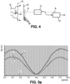
- FIG. 4 illustrates a possible implementation of the device 10.
- the device 10 for example in the form of a film which carries the patterns M of sensitive material, is arranged in the electromagnetic radiation R to be characterized, and a thermal camera 11 is arranged to capture infrared images of the surface of the support of the device 10 which carries the patterns M.
- this surface which carries the patterns M of sensitive material sensitive can be turned towards the thermal camera 11.
- the thermal camera 11 can be of one of the commercially available models, with a matrix image sensor sensitive to wavelengths which are between 3 ⁇ m and 5 ⁇ m, for example a cooled InSb type matrix sensor.
- an optical axis AA of the camera 11 can be perpendicular to the surface of the support of the device 10 which carries the patterns M. In this way, all of the patterns M of the device 10 can appear clearly in the infrared images which are captured by the camera 11.
- the electromagnetic radiation R When the electromagnetic radiation R is continuously incident on the device 10, it causes heating of some of the rectilinear segments of the patterns M, depending on the polarization of the radiation R and depending on the orientation of this polarization relative to each rectilinear segment.
- the rectilinear segments whose temperature thus increases under the effect of the radiation R then appear with higher intensities in the infrared images which are captured by the thermal camera 11.
- parasitic thermal phenomena such as thermal diffusion in the support 1, thermal diffusion in the air which is in contact with the surface of the support 1 which carries the patterns M, and thermal convection which can appear in the air near the support 1, tend to reduce the temperature differences which are generated by the radiation R between different rectilinear segments of the sensitive material, whether these segments belong to the same pattern M or to different patterns M, and between each rectilinear segment of the sensitive material and the support 1 outside the patterns M.
- the contrast of the infrared images which are captured by the thermal camera 11 is then reduced.
- the electromagnetic radiation R which is incident on the device 10 can be modulated in intensity.
- Such modulation may be applied by the source of the radiation R when possible, or by a modulation system 12 which is arranged on the path of the radiation R before this radiation reaches the device 10.
- the modulation system 12 may be a movable screen which has at least one opening, such as a wheel whose angular sectors are selectively made of material opaque or transparent to the radiation R, and which is driven in rotation by a motor at controlled speed.
- the system 12 thus applies an intensity modulation to the radiation R which is incident on the device 10, at a frequency which may be between 1 Hz (hertz) and 100 Hz, for example.
- the intensities of image points which are measured by the thermal camera 11 are then filtered by a synchronous detection system 13, in accordance with the modulation which is applied to the source of the radiation R or by the system 12.
- a synchronous detection system 13 Such an image capture mode with synchronous detection makes it possible to eliminate continuous thermal contributions which are produced by at least one of the parasitic thermal phenomena mentioned above.
- the modulated radiation R causes a series of successive temperature increase pulses in some of the rectilinear segments of the patterns M of the device 10, and these pulses are selectively detected in the infrared images after filtering by the demodulation system 13.
- the diagram of [ Fig. 5a ] shows the distribution of the electric current density which is induced in a pattern M of the device 10, for a pattern as shown in [ Fig. 2a ], when the electromagnetic radiation R which is incident on this pattern has a rectilinear polarization of the electric field, parallel to the rectilinear segment 2s.
- the sensitive material is a metal oxide whose electrical conductivity is of the order of 1000 S/m, and the width of each of the segments 2 1 -2 4 is equal to 200 ⁇ m.
- the horizontal axis marks the position along each of the segments 2 1 -2 4 , from one end of each segment to the other for a segment length equal to 20 mm. This position is noted x.
- the vertical axis marks the amplitude of the current density, noted J and expressed in arbitrary units (au).
- the curve relating to each segment of the pattern M of [ Fig. 2a ] is designated by the reference of this segment.
- the current density which is induced in segment 2 3 is the largest, since this segment 2 3 is parallel to the electric field of the radiation R, the current density which is induced in segment 2 1 is substantially zero, since this segment 2 1 is perpendicular to the electric field of the radiation R, and the current densities which are induced in segments 2 2 and 2 4 are intermediate and substantially equal, since the two segments 2 2 and 2 4 are each at 45° from the electric field.
- Segments 2 2 and 2 4 each appear in the captured images in a similar way to segment 2s, but being less bright, and segment 2 1 appears dark depending on the temperature of the support 1, except at its center where its temperature is increased due to thermal conduction from the parts close to the other segments 2 2 -2 4 .
- [ Fig. 5b ] corresponds to [ Fig. 5a ] when the sensitive material is still of the electrically conductive type, but with a much lower electrical conductivity value, of the order of 20 S/m.
- This value corresponds to a Kapton ® support 1 which has been locally heated by laser to form the sensitive material.
- the resonance behavior no longer exists, so that the amplitude of the electric current density which is induced in each segment is substantially constant outside a restricted zone around the middle of this segment. As before, this amplitude of induced current density depends on the orientation of the segment relative to the rectilinear polarization direction of the electric field of the radiation R.
- the suppression of an intersection between the segments of the same star pattern, as introduced between [ Fig. 2b] and [Fig. 2c] ] prevents the center of the star from appearing highlighted in captured infrared images.
- each segment direction in the diagram of [ Fig. 6 ] is associated with a representation length which is proportional to the heating of the segment, as read in the infrared images captured by the thermal camera 11.
- the segments 2 1 and 2 4 which are perpendicular to each other in the example considered but without this being essential, form a first rectilinear polarization base.
- the segments 2 2 and 2 5 form a second rectilinear polarization base
- the segments 2 3 and 2 6 form a third linear polarization basis.
- the ratio of the representation lengths of the two segment directions of this basis indicates two distinct directions which are possible for the linear polarization of the radiation R.
- These two possible polarization directions are symmetrical with respect to the segment directions of the base.
- the possible directions for the linear polarization of the radiation R are V 1 and V 2 , as indicated in the diagram.
- This example corresponds to the twelve-pointed star of [ Fig. 6 ], creating three orthonormal bases in the plane of the pattern M.
- the same reasoning applies to the eight-pointed star of [ Fig. 2a ], creating two orthonormal bases which will therefore give four potential directions of linear polarization, only two of which will coincide with each other to indicate the actual direction of linear polarization.
- a three-pointed star M pattern with two non-orthogonal two-by-two branches, as shown in [ Fig. 3d ] creates two non-orthonormal bases that will also give four potential directions, two of which will coincide with each other to indicate the actual linear polarization direction.
- the reasoning applies generally to any N-point star pattern that defines at least three directions.
- the method of determining the direction of rectilinear polarization which has just been described with reference to [ Fig. 6 ] can be repeated independently for several of the patterns M of the device 10.
- the direction of the rectilinear polarization of the electromagnetic radiation R is thus determined at the locations of these patterns M, so that spatial variations of this polarization can be highlighted.
- This method of determining the polarization can also be applied in a case where the polarization of the electromagnetic radiation is elliptical at the location of the pattern M which is used.
- the orientation of the axes of the polarization ellipse is then obtained, as well as possibly a value of the quotient between the respective lengths of the major axis and the minor axis of the polarization ellipse.
- rectilinear segments of sensitive material which are separated can be used to each constitute a distinct pattern, and that such patterns with a single segment per pattern can be distributed according to a random network and each oriented randomly in or on the surface of the support.
- the patterns may have random orientations in a single device that is in accordance with the invention. Furthermore, they may be distributed regularly or randomly in or on the surface of the support, including randomly on a regular grid.
Landscapes
- Physics & Mathematics (AREA)
- General Physics & Mathematics (AREA)
- Electromagnetism (AREA)
- Spectroscopy & Molecular Physics (AREA)
- Photometry And Measurement Of Optical Pulse Characteristics (AREA)
- Radiation Pyrometers (AREA)
- Investigating Or Analyzing Materials Using Thermal Means (AREA)
Claims (13)
- Vorrichtung (10) die angepasst ist, um räumliche Veränderungen einer Polarisation elektromagnetischer Strahlung (R) in Form von lokalisierten Temperaturveränderungen zu erkennen,wobei die Vorrichtung (10) eine Oberfläche eines Trägers (1) umfasst, die thermisch und elektrisch isolierend ist, und in oder auf der Oberfläche des Trägers ein Netz aus Motiven (M) beinhaltet, die jeweils aus mindestens einem geradlinigen Segment (2) eines Werkstoffs, empfindlicher Werkstoff genannt, bestehen,wobei der empfindliche Werkstoff angepasst ist, um eine Erwärmung zu erzeugen, wenn der empfindliche Werkstoff einem elektrischen Feld oder einem Magnetfeld der Strahlung (R) ausgesetzt ist, wobei sich ein Wert einer Erwärmungsleistungsrate in Bezug auf eine Leistung der elektromagnetischen Strahlung in Abhängigkeit von einer Polarisation der elektromagnetischen Strahlung in Bezug auf eine Ausrichtung eines jeden Segments (2) in der Oberfläche des Trägers (1) verändert,wobei die Erwärmungsleistungsrate in Bezug auf eine Leistung der elektromagnetischen Strahlung im Träger außerhalb der Segmente (2) des empfindlichen Werkstoffs unabhängig von der Polarisation der Strahlung (R) im Wesentlichen null ist,wobei in der Vorrichtung (10), wenn jedes Motiv (M) mehrere Segmente beinhaltet, diese Segmente (2) im Inneren eines jeden Motivs mindestens zwei unterschiedliche Ausrichtungen aufweisen, oder wobei, wenn jedes Motiv nur ein Segment beinhaltet, die Segmente zweier benachbarter Motive unterschiedliche Ausrichtungen aufweisen,wobei das Netz aus Wiederholungen eines Grundmotivs mit Versätzen in mehreren Wiederholungsrichtungen (D1, D2) besteht, die sich in der Oberfläche des Trägers (1) unterscheiden, um ein zweidimensionales Netz aus identischen Motiven (M) zu bilden,wobei die Vorrichtung (10) dadurch gekennzeichnet ist, dass der empfindliche Werkstoff ein elektrisch leitender Werkstoff ist, wobei ein elektrischen Leitfähigkeitswert des empfindlichen Werkstoffs zwischen 10 S/m und 500 S/m liegt.
- Vorrichtung (10) nach Anspruch 1, wobei jedes Motiv (M) mehrere geradlinige Segmente (2) aus empfindlichem Werkstoff beinhaltet und die Segmente eines jeden Motivs mindestens drei verschiedene Ausrichtungen in der Oberfläche des Trägers (1) im Inneren des Motivs aufweisen.
- Vorrichtung (10) nach Anspruch 1 oder 2, wobei die Versätze der Wiederholungen des Grundmotivs in zwei unterschiedlichen Wiederholungsrichtungen (D1, D2) in der Oberfläche des Trägers (1) kombiniert sind, und regelmäßig sind, sodass das zweidimensionale Netz aus identischen Motiven (M) in jeder der beiden Wiederholungsrichtungen periodisch ist, wobei eine räumliche Periode in jeder der Wiederholungsrichtungen zwischen 100 µm und 50 mm liegt, vorzugsweise zwischen 1 mm und 30 mm liegt.
- Vorrichtung (10) nach einem der vorstehenden Ansprüche, wobei zwei beliebige der Motive (M), die in der Oberfläche des Trägers (1) benachbart sind, ineinander verschränkt sind.
- Vorrichtung (10) nach einem der vorstehenden Ansprüche, wobei die Segmente (2) eines beliebigen Paares von Motiven (M) die in der Oberfläche des Trägers (1) benachbart sind, durch ein Zwischenmotivintervall, das mit keinem empfindlichen Werkstoff versehen ist, zwischen dem einen beliebigen der Segmente eines ersten Motivs des Paares und einem beliebigen der Segmente des anderen Motivs des Paares getrennt sind.
- Vorrichtung (10) nach einem der vorstehenden Ansprüche, wobei zwei beliebige der Segmente (2) eines gleichen der Motive (M) voneinander durch ein Intervall innerhalb des Motivs isoliert sind, das mit keinem empfindlichen Werkstoff versehen ist.
- Vorrichtung (10) nach einem der vorstehenden Ansprüche, wobei jedes Motiv (M) aus N Segmenten (2) besteht, die in der Oberfläche des Trägers (1) angeordnet sind, wobei N eine ganze Zahl ist, die zwischen 3 und 16 liegt, wobei die Werte 3 und 16 enthalten sind, und wobei die jeweiligen Ausrichtungen der N Segmente des einen beliebigen der Motive winkelig gleichverteilt sind.
- Vorrichtung (10) nach Anspruch 7, wobei die Segmente (2) eines jeden der Motive (M) radial um eine Mitte des Motivs angeordnet sind, um einen regelmäßigen Stern mit N Ästen in der Oberfläche des Trägers (1) zu bilden.
- Vorrichtung (10) nach einem der vorstehenden Ansprüche, wobei jedes Segment (2) eine Länge besitzt, die zwischen 50 µm und 40 mm, vorzugsweise zwischen 1 mm und 30 mm liegt, und eine Breite, die zwischen 10 µm und 500 µm, vorzugsweise zwischen 100 µm und 300 µm liegt, wobei die Länge und Breite parallel zur Oberfläche des Trägers (1) gemessen werden.
- Vorrichtung (10) nach einem der vorstehenden Ansprüche, wobei die Oberfläche des Trägers (1) aus einem organischen Werkstoff besteht, der thermisch und elektrisch isolierend ist, beispielsweise auf Basis von Polyimid, und wobei der empfindliche Werkstoff mindestens eine Zusammensetzung umfasst, die sich aus einer Änderung des organischen Werkstoffs, insbesondere einer Zusammensetzung aus thermischem Abbau des organischen Werkstoffs ergibt.
- Vorrichtung (10) nach einem der vorstehenden Ansprüche, die weiter eine Wärmekamera (11) umfasst, die angeordnet ist, um Infrarotbilder der Oberfläche des Trägers (1) aufzunehmen, während die Oberfläche des Trägers der elektromagnetischen Strahlung (R) ausgesetzt ist, um in den aufgenommenen Bildern Teile von mindestens bestimmten der Segmente (2) des empfindlichen Werkstoffs mit Intensitäten erscheinen zu lassen, die von jeweiligen Temperaturwerten der Teile von Segmenten abhängig sind.
- Vorrichtung (10) nach Anspruch 11, weiter umfassend:- ein Modulationssystem (12), das angeordnet ist, um eine zeitliche Modulationsfolge auf die elektromagnetische Strahlung (R) anzuwenden, welcher die Oberfläche des Trägers (1) ausgesetzt ist; und- ein synchrones Erkennungssystem (13), das angeordnet ist, um die in den aufeinanderfolgenden Bildern der Oberfläche des Trägers erfassten Intensitäten entsprechend der zeitlichen Modulationsfolge zu filtern.
- Verfahren zur Herstellung einer Vorrichtung (10), die angepasst ist, um räumliche Veränderungen einer Polarisation elektromagnetischer Strahlung (R) zu erkennen, wobei die Vorrichtung nach einem der vorstehenden Ansprüche ist, wobei das Verfahren zur Herstellung die folgenden Schritte umfasst:- Bereitstellen eines Trägers (1), dessen eine Oberfläche aus einem thermisch und elektrisch isolierenden organischen Werkstoff, beispielsweise einem Werkstoff auf Basis von Polyimid besteht; und- Erwärmen des organischen Werkstoffs selektiv in den bestimmten Bereichen der Oberfläche des Trägers (1), beispielsweise anhand eines Laserstrahls, der auf die Bereiche gerichtet ist, um den organischen Werkstoff lokal zu ändern, um den empfindlichen Werkstoff insbesondere durch thermischen Abbau des organischen Werkstoffs zu bilden, um die Segmente (2) aus empfindlichem Werkstoff zu erstellen.
Applications Claiming Priority (2)
| Application Number | Priority Date | Filing Date | Title |
|---|---|---|---|
| FR1910495A FR3101151B1 (fr) | 2019-09-24 | 2019-09-24 | Dispositif pour reveler des variations spatiales de polarisation d’un rayonnement electromagnetique |
| PCT/FR2020/051601 WO2021058895A1 (fr) | 2019-09-24 | 2020-09-16 | Dispositif pour reveler des variations spatiales de polarisation d'un rayonnement electromagnetique |
Publications (2)
| Publication Number | Publication Date |
|---|---|
| EP4034894A1 EP4034894A1 (de) | 2022-08-03 |
| EP4034894B1 true EP4034894B1 (de) | 2024-08-28 |
Family
ID=69468689
Family Applications (1)
| Application Number | Title | Priority Date | Filing Date |
|---|---|---|---|
| EP20820252.3A Active EP4034894B1 (de) | 2019-09-24 | 2020-09-16 | Vorrichtung zur erkennung von räumlichen veränderungen der polarisation elektromagnetischer strahlung |
Country Status (8)
| Country | Link |
|---|---|
| US (1) | US11959953B2 (de) |
| EP (1) | EP4034894B1 (de) |
| JP (1) | JP7547474B2 (de) |
| KR (1) | KR102789514B1 (de) |
| CN (1) | CN114651181B (de) |
| CA (1) | CA3153957A1 (de) |
| FR (1) | FR3101151B1 (de) |
| WO (1) | WO2021058895A1 (de) |
Families Citing this family (2)
| Publication number | Priority date | Publication date | Assignee | Title |
|---|---|---|---|---|
| FR3134449B1 (fr) * | 2022-04-11 | 2024-04-19 | Anyfields | Dispositif de mesure du rayonnement electromagnetique d’un objet rayonnant |
| CN118509333B (zh) * | 2024-07-12 | 2024-11-08 | 西安乾景防务技术有限公司 | 一种基于python的射频测试网络构建与评估方法及系统 |
Family Cites Families (16)
| Publication number | Priority date | Publication date | Assignee | Title |
|---|---|---|---|---|
| CA714673A (en) * | 1965-07-27 | H. Lady James | Thermal imaging device | |
| FR2787583B1 (fr) | 1998-12-17 | 2001-01-19 | Onera (Off Nat Aerospatiale) | Capteur de champ electromagnetique par thermographie infrarouge |
| GB0104206D0 (en) * | 2001-02-21 | 2001-04-11 | Secr Defence | Radiometers |
| FR2855609B1 (fr) | 2003-05-26 | 2005-07-01 | Commissariat Energie Atomique | Dispositif de detection bolometrique a antenne, a cavite optimisee, pour ondes electromagnetiques millimetriques ou submillimetriques, et procede de fabrication de ce dispositif |
| FR2861172B1 (fr) * | 2003-10-15 | 2006-06-02 | Ulis | Detecteur bolometrique, dispositif de detection infrarouge mettant en oeuvre un tel detecteur bolometrique et procede de fabrication de ce detecteur |
| WO2006072762A1 (en) * | 2005-01-05 | 2006-07-13 | Isis Innovation Limited | Polarization sensitive electromagnetic radiation detector |
| WO2007034380A2 (en) * | 2005-09-23 | 2007-03-29 | Nxp B.V. | Method and apparatus for polarization display of antenna |
| JP2009063345A (ja) * | 2007-09-05 | 2009-03-26 | Yasushi Maeno | 電磁界強度分布測定装置 |
| JP2009141661A (ja) | 2007-12-06 | 2009-06-25 | Optical Comb Inc | 電磁波検出素子及び電磁波検出装置 |
| JP2012529960A (ja) * | 2009-06-19 | 2012-11-29 | コーニンクレッカ フィリップス エレクトロニクス エヌ ヴィ | 軌道角運動量を持つ光子を使用した過分極装置と組み合わせたmri温度測定 |
| FR2959355B1 (fr) * | 2010-04-27 | 2012-08-17 | Inst Polytechnique Grenoble | Surface adaptee a filtrer une pluralite de bandes de frequences |
| FR2983953B1 (fr) * | 2011-12-09 | 2014-01-03 | Commissariat Energie Atomique | Detecteur bolometrique d'un rayonnement electromagnetique dans le domaine du terahertz et dispositif de detection matriciel comportant de tels detecteurs |
| JP6221572B2 (ja) | 2013-09-27 | 2017-11-01 | 株式会社デンソー | 温度センサ |
| JP6486695B2 (ja) | 2015-01-14 | 2019-03-20 | 浜松ホトニクス株式会社 | ボロメータ型THz検出器 |
| US10458851B2 (en) * | 2018-02-03 | 2019-10-29 | Keysight Technologies, Inc. | Systems and methods for thermal imaging of RF signals |
| CN109490381B (zh) | 2018-11-19 | 2020-06-02 | 北京科技大学 | 基于稀土镍基钙钛矿化合物的能量扰动交叉双向探测方法 |
-
2019
- 2019-09-24 FR FR1910495A patent/FR3101151B1/fr active Active
-
2020
- 2020-09-16 KR KR1020227013724A patent/KR102789514B1/ko active Active
- 2020-09-16 CA CA3153957A patent/CA3153957A1/fr active Pending
- 2020-09-16 CN CN202080065171.6A patent/CN114651181B/zh active Active
- 2020-09-16 EP EP20820252.3A patent/EP4034894B1/de active Active
- 2020-09-16 JP JP2022519090A patent/JP7547474B2/ja active Active
- 2020-09-16 US US17/762,987 patent/US11959953B2/en active Active
- 2020-09-16 WO PCT/FR2020/051601 patent/WO2021058895A1/fr not_active Ceased
Also Published As
| Publication number | Publication date |
|---|---|
| US11959953B2 (en) | 2024-04-16 |
| CA3153957A1 (fr) | 2021-04-01 |
| JP7547474B2 (ja) | 2024-09-09 |
| KR102789514B1 (ko) | 2025-03-31 |
| EP4034894A1 (de) | 2022-08-03 |
| FR3101151A1 (fr) | 2021-03-26 |
| FR3101151B1 (fr) | 2021-12-17 |
| WO2021058895A1 (fr) | 2021-04-01 |
| CN114651181B (zh) | 2024-10-25 |
| CN114651181A (zh) | 2022-06-21 |
| JP2022549492A (ja) | 2022-11-25 |
| US20220413028A1 (en) | 2022-12-29 |
| KR20230002262A (ko) | 2023-01-05 |
Similar Documents
| Publication | Publication Date | Title |
|---|---|---|
| EP2602598B1 (de) | Bolometrischer Detektor für elektromagnetische Strahlung im Spektralbereich von Terahertz und Matrix, die solche Detektoren umfasst | |
| EP2339647B1 (de) | Photodetektor mit Plasmonstruktur | |
| EP0749007B1 (de) | Bolometrische Detektorvorrichtung für Millimeter- und Submillimeterwellen und Herstellungsverfahren für diese Vorrichtung | |
| EP2339640A1 (de) | Photodetektor mit Plasmonstruktur | |
| CA2481056C (fr) | Detecteur bolometrique, dispositif de detection infrarouge mettant en oeuvre un tel detecteur bolometrique et procede de fabrication de ce detecteur | |
| FR3050526A1 (fr) | Dispositif de detection de rayonnement electromagnetique a structure d’encapsulation comportant au moins un filtre interferentiel | |
| WO2021058895A1 (fr) | Dispositif pour reveler des variations spatiales de polarisation d'un rayonnement electromagnetique | |
| EP2019301B1 (de) | Elektromagnetische Strahlensonde und Herstellungsverfahren einer solchen Sonde | |
| FR2795175A1 (fr) | Interferometre optique achromatique, du type a sensibilite continument reglable | |
| EP1695390B1 (de) | Fotodtektor mit nahfeldkonzentration | |
| EP2902758A1 (de) | Detektor für Photonenstrahlung, der ein Antennennetz und eine widerstandsfähige Spiralhalterung umfasst | |
| WO2005057148A1 (fr) | Dispositif de mesure d'energie rayonnante ameliore a deux positions. | |
| EP2208016B1 (de) | Optischer sensor zur messung der verformung über die zeit einer verformbaren planaren struktur | |
| FR2748604A1 (fr) | Photodetecteur a structure optique resonnante avec un reseau | |
| FR2787583A1 (fr) | Capteur de champ electromagnetique par thermographie infrarouge | |
| WO2007048778A1 (fr) | Detecteur d'ondes electromagnetiques a bande passante terahertz | |
| EP1475860A1 (de) | Vorrichtung, die eine Antenne, einen Sensor oder eine elektromagnetische Sonde bildet | |
| FR2992470A1 (fr) | Element photodetecteur pour une radiation lumineuse infrarouge et photodetecteur comprenant un tel element photodetecteur |
Legal Events
| Date | Code | Title | Description |
|---|---|---|---|
| STAA | Information on the status of an ep patent application or granted ep patent |
Free format text: STATUS: UNKNOWN |
|
| STAA | Information on the status of an ep patent application or granted ep patent |
Free format text: STATUS: THE INTERNATIONAL PUBLICATION HAS BEEN MADE |
|
| PUAI | Public reference made under article 153(3) epc to a published international application that has entered the european phase |
Free format text: ORIGINAL CODE: 0009012 |
|
| STAA | Information on the status of an ep patent application or granted ep patent |
Free format text: STATUS: REQUEST FOR EXAMINATION WAS MADE |
|
| 17P | Request for examination filed |
Effective date: 20220329 |
|
| AK | Designated contracting states |
Kind code of ref document: A1 Designated state(s): AL AT BE BG CH CY CZ DE DK EE ES FI FR GB GR HR HU IE IS IT LI LT LU LV MC MK MT NL NO PL PT RO RS SE SI SK SM TR |
|
| DAV | Request for validation of the european patent (deleted) | ||
| DAX | Request for extension of the european patent (deleted) | ||
| RAP3 | Party data changed (applicant data changed or rights of an application transferred) |
Owner name: CENTRE NATIONAL DE LA RECHERCHE SCIENTIFIQUE (CNRS) Owner name: UNIVERSITE TOULOUSE III - PAUL SABATIER Owner name: CENTRE NATIONAL D'ETUDES SPATIALES Owner name: OFFICE NATIONAL D'ETUDES ET DE RECHERCHES AEROSPATIALES |
|
| GRAP | Despatch of communication of intention to grant a patent |
Free format text: ORIGINAL CODE: EPIDOSNIGR1 |
|
| STAA | Information on the status of an ep patent application or granted ep patent |
Free format text: STATUS: GRANT OF PATENT IS INTENDED |
|
| INTG | Intention to grant announced |
Effective date: 20240404 |
|
| GRAS | Grant fee paid |
Free format text: ORIGINAL CODE: EPIDOSNIGR3 |
|
| GRAA | (expected) grant |
Free format text: ORIGINAL CODE: 0009210 |
|
| STAA | Information on the status of an ep patent application or granted ep patent |
Free format text: STATUS: THE PATENT HAS BEEN GRANTED |
|
| AK | Designated contracting states |
Kind code of ref document: B1 Designated state(s): AL AT BE BG CH CY CZ DE DK EE ES FI FR GB GR HR HU IE IS IT LI LT LU LV MC MK MT NL NO PL PT RO RS SE SI SK SM TR |
|
| REG | Reference to a national code |
Ref country code: CH Ref legal event code: EP |
|
| REG | Reference to a national code |
Ref country code: DE Ref legal event code: R096 Ref document number: 602020036794 Country of ref document: DE |
|
| REG | Reference to a national code |
Ref country code: IE Ref legal event code: FG4D Free format text: LANGUAGE OF EP DOCUMENT: FRENCH |
|
| REG | Reference to a national code |
Ref country code: LT Ref legal event code: MG9D |
|
| PG25 | Lapsed in a contracting state [announced via postgrant information from national office to epo] |
Ref country code: NO Free format text: LAPSE BECAUSE OF FAILURE TO SUBMIT A TRANSLATION OF THE DESCRIPTION OR TO PAY THE FEE WITHIN THE PRESCRIBED TIME-LIMIT Effective date: 20241128 |
|
| REG | Reference to a national code |
Ref country code: AT Ref legal event code: MK05 Ref document number: 1718516 Country of ref document: AT Kind code of ref document: T Effective date: 20240828 |
|
| PG25 | Lapsed in a contracting state [announced via postgrant information from national office to epo] |
Ref country code: PT Free format text: LAPSE BECAUSE OF FAILURE TO SUBMIT A TRANSLATION OF THE DESCRIPTION OR TO PAY THE FEE WITHIN THE PRESCRIBED TIME-LIMIT Effective date: 20241230 Ref country code: NL Free format text: LAPSE BECAUSE OF FAILURE TO SUBMIT A TRANSLATION OF THE DESCRIPTION OR TO PAY THE FEE WITHIN THE PRESCRIBED TIME-LIMIT Effective date: 20240828 Ref country code: PL Free format text: LAPSE BECAUSE OF FAILURE TO SUBMIT A TRANSLATION OF THE DESCRIPTION OR TO PAY THE FEE WITHIN THE PRESCRIBED TIME-LIMIT Effective date: 20240828 Ref country code: GR Free format text: LAPSE BECAUSE OF FAILURE TO SUBMIT A TRANSLATION OF THE DESCRIPTION OR TO PAY THE FEE WITHIN THE PRESCRIBED TIME-LIMIT Effective date: 20241129 Ref country code: FI Free format text: LAPSE BECAUSE OF FAILURE TO SUBMIT A TRANSLATION OF THE DESCRIPTION OR TO PAY THE FEE WITHIN THE PRESCRIBED TIME-LIMIT Effective date: 20240828 |
|
| PG25 | Lapsed in a contracting state [announced via postgrant information from national office to epo] |
Ref country code: BG Free format text: LAPSE BECAUSE OF FAILURE TO SUBMIT A TRANSLATION OF THE DESCRIPTION OR TO PAY THE FEE WITHIN THE PRESCRIBED TIME-LIMIT Effective date: 20240828 |
|
| PG25 | Lapsed in a contracting state [announced via postgrant information from national office to epo] |
Ref country code: LV Free format text: LAPSE BECAUSE OF FAILURE TO SUBMIT A TRANSLATION OF THE DESCRIPTION OR TO PAY THE FEE WITHIN THE PRESCRIBED TIME-LIMIT Effective date: 20240828 |
|
| REG | Reference to a national code |
Ref country code: NL Ref legal event code: MP Effective date: 20240828 |
|
| PG25 | Lapsed in a contracting state [announced via postgrant information from national office to epo] |
Ref country code: AT Free format text: LAPSE BECAUSE OF FAILURE TO SUBMIT A TRANSLATION OF THE DESCRIPTION OR TO PAY THE FEE WITHIN THE PRESCRIBED TIME-LIMIT Effective date: 20240828 Ref country code: IS Free format text: LAPSE BECAUSE OF FAILURE TO SUBMIT A TRANSLATION OF THE DESCRIPTION OR TO PAY THE FEE WITHIN THE PRESCRIBED TIME-LIMIT Effective date: 20241228 |
|
| PG25 | Lapsed in a contracting state [announced via postgrant information from national office to epo] |
Ref country code: HR Free format text: LAPSE BECAUSE OF FAILURE TO SUBMIT A TRANSLATION OF THE DESCRIPTION OR TO PAY THE FEE WITHIN THE PRESCRIBED TIME-LIMIT Effective date: 20240828 |
|
| PG25 | Lapsed in a contracting state [announced via postgrant information from national office to epo] |
Ref country code: ES Free format text: LAPSE BECAUSE OF FAILURE TO SUBMIT A TRANSLATION OF THE DESCRIPTION OR TO PAY THE FEE WITHIN THE PRESCRIBED TIME-LIMIT Effective date: 20240828 Ref country code: RS Free format text: LAPSE BECAUSE OF FAILURE TO SUBMIT A TRANSLATION OF THE DESCRIPTION OR TO PAY THE FEE WITHIN THE PRESCRIBED TIME-LIMIT Effective date: 20241128 |
|
| PG25 | Lapsed in a contracting state [announced via postgrant information from national office to epo] |
Ref country code: RS Free format text: LAPSE BECAUSE OF FAILURE TO SUBMIT A TRANSLATION OF THE DESCRIPTION OR TO PAY THE FEE WITHIN THE PRESCRIBED TIME-LIMIT Effective date: 20241128 Ref country code: PT Free format text: LAPSE BECAUSE OF FAILURE TO SUBMIT A TRANSLATION OF THE DESCRIPTION OR TO PAY THE FEE WITHIN THE PRESCRIBED TIME-LIMIT Effective date: 20241230 Ref country code: PL Free format text: LAPSE BECAUSE OF FAILURE TO SUBMIT A TRANSLATION OF THE DESCRIPTION OR TO PAY THE FEE WITHIN THE PRESCRIBED TIME-LIMIT Effective date: 20240828 Ref country code: NO Free format text: LAPSE BECAUSE OF FAILURE TO SUBMIT A TRANSLATION OF THE DESCRIPTION OR TO PAY THE FEE WITHIN THE PRESCRIBED TIME-LIMIT Effective date: 20241128 Ref country code: NL Free format text: LAPSE BECAUSE OF FAILURE TO SUBMIT A TRANSLATION OF THE DESCRIPTION OR TO PAY THE FEE WITHIN THE PRESCRIBED TIME-LIMIT Effective date: 20240828 Ref country code: LV Free format text: LAPSE BECAUSE OF FAILURE TO SUBMIT A TRANSLATION OF THE DESCRIPTION OR TO PAY THE FEE WITHIN THE PRESCRIBED TIME-LIMIT Effective date: 20240828 Ref country code: IS Free format text: LAPSE BECAUSE OF FAILURE TO SUBMIT A TRANSLATION OF THE DESCRIPTION OR TO PAY THE FEE WITHIN THE PRESCRIBED TIME-LIMIT Effective date: 20241228 Ref country code: HR Free format text: LAPSE BECAUSE OF FAILURE TO SUBMIT A TRANSLATION OF THE DESCRIPTION OR TO PAY THE FEE WITHIN THE PRESCRIBED TIME-LIMIT Effective date: 20240828 Ref country code: GR Free format text: LAPSE BECAUSE OF FAILURE TO SUBMIT A TRANSLATION OF THE DESCRIPTION OR TO PAY THE FEE WITHIN THE PRESCRIBED TIME-LIMIT Effective date: 20241129 Ref country code: FI Free format text: LAPSE BECAUSE OF FAILURE TO SUBMIT A TRANSLATION OF THE DESCRIPTION OR TO PAY THE FEE WITHIN THE PRESCRIBED TIME-LIMIT Effective date: 20240828 Ref country code: ES Free format text: LAPSE BECAUSE OF FAILURE TO SUBMIT A TRANSLATION OF THE DESCRIPTION OR TO PAY THE FEE WITHIN THE PRESCRIBED TIME-LIMIT Effective date: 20240828 Ref country code: BG Free format text: LAPSE BECAUSE OF FAILURE TO SUBMIT A TRANSLATION OF THE DESCRIPTION OR TO PAY THE FEE WITHIN THE PRESCRIBED TIME-LIMIT Effective date: 20240828 Ref country code: AT Free format text: LAPSE BECAUSE OF FAILURE TO SUBMIT A TRANSLATION OF THE DESCRIPTION OR TO PAY THE FEE WITHIN THE PRESCRIBED TIME-LIMIT Effective date: 20240828 |
|
| PG25 | Lapsed in a contracting state [announced via postgrant information from national office to epo] |
Ref country code: SM Free format text: LAPSE BECAUSE OF FAILURE TO SUBMIT A TRANSLATION OF THE DESCRIPTION OR TO PAY THE FEE WITHIN THE PRESCRIBED TIME-LIMIT Effective date: 20240828 Ref country code: DK Free format text: LAPSE BECAUSE OF FAILURE TO SUBMIT A TRANSLATION OF THE DESCRIPTION OR TO PAY THE FEE WITHIN THE PRESCRIBED TIME-LIMIT Effective date: 20240828 Ref country code: RO Free format text: LAPSE BECAUSE OF FAILURE TO SUBMIT A TRANSLATION OF THE DESCRIPTION OR TO PAY THE FEE WITHIN THE PRESCRIBED TIME-LIMIT Effective date: 20240828 |
|
| PG25 | Lapsed in a contracting state [announced via postgrant information from national office to epo] |
Ref country code: EE Free format text: LAPSE BECAUSE OF FAILURE TO SUBMIT A TRANSLATION OF THE DESCRIPTION OR TO PAY THE FEE WITHIN THE PRESCRIBED TIME-LIMIT Effective date: 20240828 |
|
| PG25 | Lapsed in a contracting state [announced via postgrant information from national office to epo] |
Ref country code: CZ Free format text: LAPSE BECAUSE OF FAILURE TO SUBMIT A TRANSLATION OF THE DESCRIPTION OR TO PAY THE FEE WITHIN THE PRESCRIBED TIME-LIMIT Effective date: 20240828 |
|
| PG25 | Lapsed in a contracting state [announced via postgrant information from national office to epo] |
Ref country code: SK Free format text: LAPSE BECAUSE OF FAILURE TO SUBMIT A TRANSLATION OF THE DESCRIPTION OR TO PAY THE FEE WITHIN THE PRESCRIBED TIME-LIMIT Effective date: 20240828 Ref country code: IT Free format text: LAPSE BECAUSE OF FAILURE TO SUBMIT A TRANSLATION OF THE DESCRIPTION OR TO PAY THE FEE WITHIN THE PRESCRIBED TIME-LIMIT Effective date: 20240828 |
|
| REG | Reference to a national code |
Ref country code: CH Ref legal event code: PL |
|
| PG25 | Lapsed in a contracting state [announced via postgrant information from national office to epo] |
Ref country code: LU Free format text: LAPSE BECAUSE OF NON-PAYMENT OF DUE FEES Effective date: 20240916 |
|
| REG | Reference to a national code |
Ref country code: DE Ref legal event code: R097 Ref document number: 602020036794 Country of ref document: DE |
|
| PLBE | No opposition filed within time limit |
Free format text: ORIGINAL CODE: 0009261 |
|
| STAA | Information on the status of an ep patent application or granted ep patent |
Free format text: STATUS: NO OPPOSITION FILED WITHIN TIME LIMIT |
|
| PG25 | Lapsed in a contracting state [announced via postgrant information from national office to epo] |
Ref country code: MC Free format text: LAPSE BECAUSE OF FAILURE TO SUBMIT A TRANSLATION OF THE DESCRIPTION OR TO PAY THE FEE WITHIN THE PRESCRIBED TIME-LIMIT Effective date: 20240828 |
|
| REG | Reference to a national code |
Ref country code: BE Ref legal event code: MM Effective date: 20240930 |
|
| PG25 | Lapsed in a contracting state [announced via postgrant information from national office to epo] |
Ref country code: BE Free format text: LAPSE BECAUSE OF NON-PAYMENT OF DUE FEES Effective date: 20240930 |
|
| PG25 | Lapsed in a contracting state [announced via postgrant information from national office to epo] |
Ref country code: CH Free format text: LAPSE BECAUSE OF NON-PAYMENT OF DUE FEES Effective date: 20240930 |
|
| PG25 | Lapsed in a contracting state [announced via postgrant information from national office to epo] |
Ref country code: IE Free format text: LAPSE BECAUSE OF NON-PAYMENT OF DUE FEES Effective date: 20240916 |
|
| 26N | No opposition filed |
Effective date: 20250530 |
|
| PG25 | Lapsed in a contracting state [announced via postgrant information from national office to epo] |
Ref country code: SE Free format text: LAPSE BECAUSE OF FAILURE TO SUBMIT A TRANSLATION OF THE DESCRIPTION OR TO PAY THE FEE WITHIN THE PRESCRIBED TIME-LIMIT Effective date: 20240828 |
|
| PGFP | Annual fee paid to national office [announced via postgrant information from national office to epo] |
Ref country code: GB Payment date: 20250929 Year of fee payment: 6 |
|
| PGFP | Annual fee paid to national office [announced via postgrant information from national office to epo] |
Ref country code: FR Payment date: 20250929 Year of fee payment: 6 |
|
| PGFP | Annual fee paid to national office [announced via postgrant information from national office to epo] |
Ref country code: DE Payment date: 20251029 Year of fee payment: 6 |
|
| PG25 | Lapsed in a contracting state [announced via postgrant information from national office to epo] |
Ref country code: CY Free format text: LAPSE BECAUSE OF FAILURE TO SUBMIT A TRANSLATION OF THE DESCRIPTION OR TO PAY THE FEE WITHIN THE PRESCRIBED TIME-LIMIT; INVALID AB INITIO Effective date: 20200916 |
|
| PG25 | Lapsed in a contracting state [announced via postgrant information from national office to epo] |
Ref country code: HU Free format text: LAPSE BECAUSE OF FAILURE TO SUBMIT A TRANSLATION OF THE DESCRIPTION OR TO PAY THE FEE WITHIN THE PRESCRIBED TIME-LIMIT; INVALID AB INITIO Effective date: 20200916 |