EP4034455B1 - A floating metal platform - Google Patents
A floating metal platform Download PDFInfo
- Publication number
- EP4034455B1 EP4034455B1 EP20780152.3A EP20780152A EP4034455B1 EP 4034455 B1 EP4034455 B1 EP 4034455B1 EP 20780152 A EP20780152 A EP 20780152A EP 4034455 B1 EP4034455 B1 EP 4034455B1
- Authority
- EP
- European Patent Office
- Prior art keywords
- elongated
- platform
- wind turbine
- elements
- elongated member
- Prior art date
- Legal status (The legal status is an assumption and is not a legal conclusion. Google has not performed a legal analysis and makes no representation as to the accuracy of the status listed.)
- Active
Links
Images








Classifications
-
- B—PERFORMING OPERATIONS; TRANSPORTING
- B63—SHIPS OR OTHER WATERBORNE VESSELS; RELATED EQUIPMENT
- B63B—SHIPS OR OTHER WATERBORNE VESSELS; EQUIPMENT FOR SHIPPING
- B63B35/00—Vessels or similar floating structures specially adapted for specific purposes and not otherwise provided for
- B63B35/44—Floating buildings, stores, drilling platforms, or workshops, e.g. carrying water-oil separating devices
-
- B—PERFORMING OPERATIONS; TRANSPORTING
- B63—SHIPS OR OTHER WATERBORNE VESSELS; RELATED EQUIPMENT
- B63B—SHIPS OR OTHER WATERBORNE VESSELS; EQUIPMENT FOR SHIPPING
- B63B1/00—Hydrodynamic or hydrostatic features of hulls or of hydrofoils
- B63B1/02—Hydrodynamic or hydrostatic features of hulls or of hydrofoils deriving lift mainly from water displacement
- B63B1/10—Hydrodynamic or hydrostatic features of hulls or of hydrofoils deriving lift mainly from water displacement with multiple hulls
- B63B1/12—Hydrodynamic or hydrostatic features of hulls or of hydrofoils deriving lift mainly from water displacement with multiple hulls the hulls being interconnected rigidly
- B63B1/125—Hydrodynamic or hydrostatic features of hulls or of hydrofoils deriving lift mainly from water displacement with multiple hulls the hulls being interconnected rigidly comprising more than two hulls
-
- F—MECHANICAL ENGINEERING; LIGHTING; HEATING; WEAPONS; BLASTING
- F03—MACHINES OR ENGINES FOR LIQUIDS; WIND, SPRING, OR WEIGHT MOTORS; PRODUCING MECHANICAL POWER OR A REACTIVE PROPULSIVE THRUST, NOT OTHERWISE PROVIDED FOR
- F03D—WIND MOTORS
- F03D13/00—Assembly, mounting or commissioning of wind motors; Arrangements specially adapted for transporting wind motor components
- F03D13/20—Arrangements for mounting or supporting wind motors; Masts or towers for wind motors
- F03D13/25—Arrangements for mounting or supporting wind motors; Masts or towers for wind motors specially adapted for offshore installation
-
- F—MECHANICAL ENGINEERING; LIGHTING; HEATING; WEAPONS; BLASTING
- F03—MACHINES OR ENGINES FOR LIQUIDS; WIND, SPRING, OR WEIGHT MOTORS; PRODUCING MECHANICAL POWER OR A REACTIVE PROPULSIVE THRUST, NOT OTHERWISE PROVIDED FOR
- F03D—WIND MOTORS
- F03D13/00—Assembly, mounting or commissioning of wind motors; Arrangements specially adapted for transporting wind motor components
- F03D13/20—Arrangements for mounting or supporting wind motors; Masts or towers for wind motors
- F03D13/25—Arrangements for mounting or supporting wind motors; Masts or towers for wind motors specially adapted for offshore installation
- F03D13/256—Arrangements for mounting or supporting wind motors; Masts or towers for wind motors specially adapted for offshore installation on a floating support, i.e. floating wind motors
-
- B—PERFORMING OPERATIONS; TRANSPORTING
- B63—SHIPS OR OTHER WATERBORNE VESSELS; RELATED EQUIPMENT
- B63B—SHIPS OR OTHER WATERBORNE VESSELS; EQUIPMENT FOR SHIPPING
- B63B1/00—Hydrodynamic or hydrostatic features of hulls or of hydrofoils
- B63B1/02—Hydrodynamic or hydrostatic features of hulls or of hydrofoils deriving lift mainly from water displacement
- B63B1/10—Hydrodynamic or hydrostatic features of hulls or of hydrofoils deriving lift mainly from water displacement with multiple hulls
- B63B1/12—Hydrodynamic or hydrostatic features of hulls or of hydrofoils deriving lift mainly from water displacement with multiple hulls the hulls being interconnected rigidly
- B63B2001/128—Hydrodynamic or hydrostatic features of hulls or of hydrofoils deriving lift mainly from water displacement with multiple hulls the hulls being interconnected rigidly comprising underwater connectors between the hulls
-
- B—PERFORMING OPERATIONS; TRANSPORTING
- B63—SHIPS OR OTHER WATERBORNE VESSELS; RELATED EQUIPMENT
- B63B—SHIPS OR OTHER WATERBORNE VESSELS; EQUIPMENT FOR SHIPPING
- B63B35/00—Vessels or similar floating structures specially adapted for specific purposes and not otherwise provided for
- B63B35/44—Floating buildings, stores, drilling platforms, or workshops, e.g. carrying water-oil separating devices
- B63B2035/4433—Floating structures carrying electric power plants
- B63B2035/446—Floating structures carrying electric power plants for converting wind energy into electric energy
-
- F—MECHANICAL ENGINEERING; LIGHTING; HEATING; WEAPONS; BLASTING
- F05—INDEXING SCHEMES RELATING TO ENGINES OR PUMPS IN VARIOUS SUBCLASSES OF CLASSES F01-F04
- F05B—INDEXING SCHEME RELATING TO WIND, SPRING, WEIGHT, INERTIA OR LIKE MOTORS, TO MACHINES OR ENGINES FOR LIQUIDS COVERED BY SUBCLASSES F03B, F03D AND F03G
- F05B2240/00—Components
- F05B2240/90—Mounting on supporting structures or systems
- F05B2240/93—Mounting on supporting structures or systems on a structure floating on a liquid surface
-
- F—MECHANICAL ENGINEERING; LIGHTING; HEATING; WEAPONS; BLASTING
- F05—INDEXING SCHEMES RELATING TO ENGINES OR PUMPS IN VARIOUS SUBCLASSES OF CLASSES F01-F04
- F05B—INDEXING SCHEME RELATING TO WIND, SPRING, WEIGHT, INERTIA OR LIKE MOTORS, TO MACHINES OR ENGINES FOR LIQUIDS COVERED BY SUBCLASSES F03B, F03D AND F03G
- F05B2240/00—Components
- F05B2240/90—Mounting on supporting structures or systems
- F05B2240/95—Mounting on supporting structures or systems offshore
-
- Y—GENERAL TAGGING OF NEW TECHNOLOGICAL DEVELOPMENTS; GENERAL TAGGING OF CROSS-SECTIONAL TECHNOLOGIES SPANNING OVER SEVERAL SECTIONS OF THE IPC; TECHNICAL SUBJECTS COVERED BY FORMER USPC CROSS-REFERENCE ART COLLECTIONS [XRACs] AND DIGESTS
- Y02—TECHNOLOGIES OR APPLICATIONS FOR MITIGATION OR ADAPTATION AGAINST CLIMATE CHANGE
- Y02B—CLIMATE CHANGE MITIGATION TECHNOLOGIES RELATED TO BUILDINGS, e.g. HOUSING, HOUSE APPLIANCES OR RELATED END-USER APPLICATIONS
- Y02B10/00—Integration of renewable energy sources in buildings
- Y02B10/30—Wind power
-
- Y—GENERAL TAGGING OF NEW TECHNOLOGICAL DEVELOPMENTS; GENERAL TAGGING OF CROSS-SECTIONAL TECHNOLOGIES SPANNING OVER SEVERAL SECTIONS OF THE IPC; TECHNICAL SUBJECTS COVERED BY FORMER USPC CROSS-REFERENCE ART COLLECTIONS [XRACs] AND DIGESTS
- Y02—TECHNOLOGIES OR APPLICATIONS FOR MITIGATION OR ADAPTATION AGAINST CLIMATE CHANGE
- Y02E—REDUCTION OF GREENHOUSE GAS [GHG] EMISSIONS, RELATED TO ENERGY GENERATION, TRANSMISSION OR DISTRIBUTION
- Y02E10/00—Energy generation through renewable energy sources
- Y02E10/70—Wind energy
- Y02E10/72—Wind turbines with rotation axis in wind direction
-
- Y—GENERAL TAGGING OF NEW TECHNOLOGICAL DEVELOPMENTS; GENERAL TAGGING OF CROSS-SECTIONAL TECHNOLOGIES SPANNING OVER SEVERAL SECTIONS OF THE IPC; TECHNICAL SUBJECTS COVERED BY FORMER USPC CROSS-REFERENCE ART COLLECTIONS [XRACs] AND DIGESTS
- Y02—TECHNOLOGIES OR APPLICATIONS FOR MITIGATION OR ADAPTATION AGAINST CLIMATE CHANGE
- Y02E—REDUCTION OF GREENHOUSE GAS [GHG] EMISSIONS, RELATED TO ENERGY GENERATION, TRANSMISSION OR DISTRIBUTION
- Y02E10/00—Energy generation through renewable energy sources
- Y02E10/70—Wind energy
- Y02E10/727—Offshore wind turbines
Definitions
- the present invention relates to floating metal platforms, in particular a floating wind turbine metal platform.
- Prior art semi submersible wind turbine platforms rely on either concrete or stiffened shell floating bodies located at the structural perimeter that is joined to the centre by either concrete elements or truss work.
- Such reinforced concrete, truss work from tubular members and stiffened shells are labour intensive and challenging to fabricate by automated mass production.
- the design philosophy of the invention redefines the design drivers for floating support structures for offshore wind.
- Previous art relies on generic methods conceived during the pioneer era of the offshore oil and gas industry. While these methods are sophisticated and allow for high structural optimization with respect to weight and motion, they do not address the fundamental challenges in floating offshore wind.
- the renewable energy market for support structures is low margin, but the number of units per project are high.
- This realization dictates a reformulation of design drivers where now focus should be shifted from optimization of weight and motion to utilizing the high numbers to achieve cost reduction.
- serial production friendliness are not enough.
- the intersection between these needs and premises, the bridging technology, is the concept emerging from the invention design philosophy.
- the invention satisfies the serial production friendliness requirement and can be produced with minimal changes to the production line at the monopile manufacturers. That means that the biggest hurdle, the big up-front investment, is circumvented.
- the columns must be made substantially of steel. While the column walls of the invention may be sandwich elements with steel surface and concrete core, they will never be reinforced concrete as found in typical concrete structure floating bodies. There exists no automated large-scale process that suit such composite material.
- An objective of the present invention is to provide a floating metal platform which is more suited for mass-production than the prior art wind platforms.
- ⁇ Connected is to be construed as directly or indirectly connected, e.g. via an intermediate part.
- the floating metal platform may be constructed without the use of concrete.
- the floating metal platform may be completely constructed by metal. Steel and aluminium are examples of preferred metals.
- the first and second elongated elements may be vertically aligned, horizontally aligned, or something therebetween.
- the first elongated member comprises a first end portion, a second opposite end portion and therebetween an intermediate portion.
- the second elongated member comprises a first end portion, a second opposite end portion and therebetween an intermediate portion. At least the first buoyancy element is directly connected to the intermediate portions of the first elongated member and the second elongated member
- buoyancy elements are incorporated into the elongated elements, i.e. used as a structural element in addition to providing buoyancy.
- the buoyancy elements may thus at least partly provide the required stiffness to the elongated elements, which in turn provides the stiffness of the floating platform.
- buoyancy elements can be distributed more evenly along the elongated element instead of only being positioned at each end.
- the elongated element may be self-supporting.
- Each elongated element may comprise a plurality of buoyancy elements.
- One buoyancy element may be connected to the first end portions of the first and second elongated members.
- One buoyancy element may be connected to the second end portions of the first and second elongated members.
- Two connected elongated elements may have one common buoyancy element.
- a plurality of buoyancy elements may be connected to the intermediate portions of the first and second elongated members.
- the first buoyancy element may comprise a first end surface and an opposite second end surface.
- the first elongated member may be connected to the first end surface of the first buoyancy element, and the second elongated member may be connected to the second end surface of the first buoyancy element.
- An advantage of this configuration is that a more compact construction can be achieved.
- the elongated member may be a pipe, a plate, a curved plate, a stiffened plate, a sandwich structure, have a corrugated cross-section or a sheet piling cross-section.
- the offshore installation may be a renewable energy installation, a mining installation, a food production installation, a desalination installation or a hydrocarbon production installation.
- the offshore installation may be a wind turbine, a wave energy converter, a solar panel, an aqua culture or a building.
- the elongated elements may be arranged in the same plane.
- Each elongated element may further comprise: a third elongated member parallel to the first and second elongated members, and a second buoyancy element connected to the second elongated member and the third elongated member.
- the first buoyancy element and the second buoyancy element (114b) are connected to opposite sides of the second elongated member (112) and arranged in alignment with each other.
- the first buoyancy element and the second buoyancy element may be connected to opposite sides of the second elongated member and arranged in misalignment with each other.
- Each elongated element comprises stiffening means for stiffening of parallel elongated members.
- At least one buoyancy element is cylinder-shaped. If cylinder-shaped, buoyancy elements will have a centre axis.
- the elongated elements may be arranged such that the centre axis of the buoyancy element points substantially in the vertical direction when the platform is floating in a body of water.
- the elongated element may be oriented such that the centre axis of the buoyancy element points substantially in the horizontal direction when the platform is floating in a body of water.
- the elongated element may be oriented such that the centre axis of the buoyancy element points in an arbitrary direction when the platform is floating in a body of water.
- the at least one buoyancy element may comprise: an outer liner, an inner liner concentric to the outer liner and having a smaller diameter than the outer liner, an annulus between the outer liner and the inner liner.
- the annulus may be filled with concrete.
- the at least one buoyancy element may have a planar interface with at least two of the first elongated member, the second elongated member and/or the third elongated member.
- the metal platform may comprise a centre hub having a centre axis, and the tower may extend along the centre axis.
- the floating wind turbine may further comprise a central column connected to the platform extending in an opposite direction of the tower and preferably arranged concentric with the tower.
- the floating wind turbine may further comprise stay cables having first ends connected to the elongated elements and second ends connected to the central column.
- the step of providing an elongated element may further comprise connecting at least a second buoyancy element to the second elongated member and a third elongated member parallel to the first and second elongated members.
- the method may further comprise the step of stiffening two parallel elongated members using stiffening means connected to said elongated members.
- the method may further comprise the steps of: providing a centre hub connectable to at least three elongated elements; and connecting one of the first end or the second end of each of the elongated elements to one of the first end or the second end of at least one of the other elongated elements via the centre hub.
- a floating wind turbine metal platform wherein the platform comprises: a centre hub; and at least three elongated elements connected to the centre hub, said elongated elements being arranged in the same plane with regular angular spacing, and each elongated element comprises: a first elongated member; a second elongated member parallel to the first elongated member; and at least one buoyancy element connected to the first elongated member and the second elongated member.
- the floating platform may be constructed without the use of concrete.
- the floating platform may be completely constructed by metal. Steel and aluminium are examples of preferred metals.
- the angular spacing between neighbouring elongated elements may be 120 degrees. If four elongated elements are connected to the centre hub, the angular spacing between neighbouring elongated elements may be 90 degrees. If five elongated elements are connected to the centre hub, the angular spacing between neighbouring elongated elements may be 72 degrees. If six elongated elements are connected to the centre hub, the angular spacing between neighbouring elongated elements may be 60 degrees.
- the centre hub may comprise attaching means for connecting to the elongated elements, such as a bolted interface.
- the centre hub and the elongated elements may be welded together.
- the centre hub may comprise a body, which can be a hollow body with one or several open ends.
- the body may be cylinder-shaped and have a vertically oriented centre axis.
- the hollow body may have a polygonal cross-section.
- the body may be a buoyancy element.
- the body may be suitable for connecting to a wind turbine tower.
- the centre hub may comprise flanges suitable for connecting to the elongated members of the elongated element. Such flanges may be connected to the body of the centre hub.
- the elongated elements of a platform may have the same size; however, the elongated elements of a platform may also have different sizes.
- Mooring supports may be provided on the elongated elements, typically at the end of the elongated elements.
- the elongated member may be any extruded member, a rolled member, a pipe, or a plate with or without stiffeners.
- Some stiffeners which may be used are e.g. flat stiffener, angle stiffener, tee stiffener (e.g. H-beam or I-beam), box stiffener, box stiffener, bulb flat stiffener, riveted angle stiffener, single side sided stiffener, double sided stiffener and multi-leg stiffener.
- the elongated member may also be a laminated structure.
- the elongated member may have a sandwich structure, e.g. two layers of metal with an intermediate layer of concrete.
- the elongated member will typically define the length and width of the elongated element.
- the buoyancy elements may typically be hollow bodies.
- the buoyancy elements may be massive bodies with lower density than seawater.
- the buoyancy elements may comprise ballasting means. It is thus achieved improved stability of the platform. It is thus achieved adjustability of the dynamic properties of the platform. It may thus be achieved a low draft, e.g. during transport inshore or at quay.
- the ballasting means enables raising of the turbine during fabrication.
- the buoyancy elements of an elongated element may have different shapes.
- the width of the buoyancy element may be different from the width of the elongated member.
- each elongated element may further comprise: a third elongated member parallel to the first and second elongated members; and at least one buoyancy element connected to the second elongated member and the third elongated member.
- Such multi layered elongated element configurations will enhance scalability and reduce the need for stiffening means by overlapping the buoyancy elements between the layers.
- At least one of the buoyancy elements connected to the first elongated member and the second elongated member may be arranged at a distance from the centre hub different than a distance from the centre hub to any of the buoyancy elements connected to the second elongated member and the third elongated member.
- the buoyancy elements connected to the first elongated member and the second elongated member and the buoyancy elements connected to the second elongated member and the third elongated member may be arranged by pairs at corresponding distances from the centre hub.
- the distribution of the buoyancy elements within an elongated element will affect the strength and stability of the elongated element.
- Each elongated element may further comprise stiffening means for stiffening of parallel elongated members.
- the stiffening means may be mechanically fastened or welded to the structure.
- means for mechanically fastening are anchor and shoe, bolts and nuts, screws, nails, rivets, glue, tongue and groove.
- Said stiffening means may be pre-tensioned to any required value or alternatively not pre-tensioned at all.
- Said stiffening means may balance the discontinued vertical shear in the gap between the buoyancy elements.
- Said stiffening means may be arranged such that they pairwise substantially form an X-shape.
- Said X-shaped pairwise stiffening means will when pre-tensioned exercise forces on the elongated members and buoyancy elements. Said forces will be balanced by compression in the first elongated member, the second elongated member and buoyancy elements.
- the first principal stress tensor substantially normal to the weld can be designed to be compressive in most of the dynamic range and significantly improve fatigue performance.
- stiffening means may be arranged singly.
- Stiffening may be achieved by stiffening means such as pre-tensioned cables, strands, rods, bars, tubulars or other beam cross sections connecting between the elongated members. Stiffening may also be achieved by additional stiffeners included in the elongated members.
- the buoyancy elements may be cylinder-shaped.
- the buoyancy elements may comprise: an outer liner; an inner liner concentric to the outer liner and having a smaller diameter than the outer liner; and an annulus between the outer liner and the inner liner; wherein the annulus may be filled with concrete.
- Such sandwich construction is well suited for mass-production.
- the buoyancy elements may have planar interfaces with at least two of the first elongated member, the second elongated member and/or the third elongated member. It an elongated element comprises a plurality of elongated elements, the buoyancy elements of this elongated element may have planar interfaces with any of said elongated members.
- the floating wind turbine may comprise: a metal platform according to any aspect of the invention; a tower connected to the platform and extending along a centre axis of the centre hub of the platform; and a horizontal axis wind turbine connected to the tower.
- the floating wind turbine may further comprise stay cables having first ends connected to the elongated elements and second ends connected to the tower.
- the floating wind turbine may further comprise a central column connected to the platform extending in an opposite direction of the tower and preferably arranged concentric with the tower.
- the floating wind turbine may further comprise stay cables having first ends connected to the elongated elements and second ends connected to the central column.
- the floating wind turbine may be used offshore.
- the floating wind turbine may be a columns-stabilized unit, a semi-submergible, a spar design or any combination of these.
- a method for assembling a floating wind turbine metal platform comprising the steps of: providing an elongated element by connecting at least one buoyancy element to an elongated first member and an elongated second member parallel to the first elongated member; providing a centre hub connectable to at least three elongated elements; and connecting at least three elongated elements to the centre hub.
- the step of providing an elongated element may further comprise connecting at least one buoyancy element to the elongated second member and an elongated third member parallel to the first and second elongated members.
- the method may further comprise the step of pre-tensioning two parallel elongated members using stiffening means connected to said elongated members.
- the floating platform doesn't require investments in new fabrication line.
- the so called monopile, tower or any other serial produced large diameter cylindrical steel element can be used as a buoyancy element directly. I.e. the invention transforms existing unrelated structural elements, the monopile, into new application.
- the floating platform has a reduced structural complexity compared to prior art solutions, which increases fabrication yard availability.
- the floating platform utilizes stiffened plates and simple stiffening means for structural strength instead of complex pontoon structures seen in prior art semi-submersibles.
- the floating platform enables a high degree of automation during fabrication, which limits human hazardous exposure. It is foreseen that, as for O&G, the HSE focus in floating offshore wind will increase with time and "human free intervention" will become more and more attractive.
- FIG. 10 shows an exploded perspective view of a floating wind turbine platform 100 is shown.
- the floating wind turbine platform 100 may comprise three elongated elements 110 connected to a central hub 120.
- FIG. 1 shows a schematic perspective view of a floating wind turbine platform 100.
- the floating wind turbine platform 100 may comprise three elongated elements 110 connected to a central hub 120.
- Each elongated element 110 may comprises three buoyancy elements 114 arranged between a first elongated member 111 and a second elongated member 112.
- Stiffening means 115 may be connected to the first elongated member 111 and a second elongated member 112 between the buoyancy element 114.
- Said central hub 120 may comprise a first flange 121 and a second flange 122 which may connect to the first elongated member 111 and the second elongated member 112 respectively, joining the elongated elements 110 with the central hub 120.
- Said central hub 120 may also comprise a body 124 connected to the first flange 121 and the second flange 122.
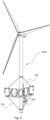
- FIG. 2 illustrates a floating wind turbine 1000 comprising a floating wind turbine platform 100, a tower 200 and a horizontal axis wind turbine 300.
- the floating wind turbine 1000 may comprise a vertical axis turbine (not illustrated).
- FIG. 4 shows that a floating wind turbine 1000 may comprise stay cables 500 connected between the tower 200 and the floating wind turbine platform 100.
- FIG. 5 shows that a central column 400 may be extended below the floating wind turbine platform 100.
- Said extended central column 400 may be connected to the floating wind turbine platform 100 by means of stay cables 500.
- These lower stay cables 500 will balance the force from the upper stay cables 52 and form an equilibrium by triangle of forces.
- FIG. 6 shows a schematic perspective view of a floating wind turbine platform 100.
- the floating wind turbine platform 100 may comprise elongated elements 110 of a double layered elongated element 110 configuration connected to a centre hub 120.
- Each double layered elongated element 110 configuration may comprise two layers of three buoyancy elements 114a, 114b.
- the three first buoyancy elements 114a arranged in an upper-layer may be arranged between a first elongated member 111 and a second elongated member 112.
- the three second buoyancy elements 114b arranged in a lower-layer may be arranged between the second elongated member 112 and a third elongated member 113.
- Said three upper-layer first buoyancy elements 114a may substantially coincide with the three lower-layer second buoyancy elements 114b in the horizontal plane, as shown in FIG. 6 .
- Stiffening means 115 may be connected to the first elongated member 111 and the second elongated member 112, between the first buoyancy elements 114a. Stiffening means 115 may be connected to the second elongated member 112 and the third elongated member 113, between the second buoyancy elements 114b.
- Said centre hub 120 may comprise a first flange 121, a second flange 122 and a third flange 123 which may connect to the first elongated member 111, the second elongated member 112 and the third elongated member 113, respectively, joining the elongated element 110 with the centre hub 110.
- Said centre hub 120 may comprise a body 124 connected to the first flange 121, the second flange 122 and the third flange 123.
- FIG. 7 shows a schematic perspective view of a floating wind turbine platform 100.
- the floating wind turbine platform 100 may comprise elongated elements 110 of a double layered elongated element 110 configuration which may be connected to a centre hub 120.
- Each double layered elongated element 110 configuration may comprise two layers of four buoyancy elements 114a, 114b.
- the four first buoyancy elements 114a arranged in an upper-layer may be arranged between a first elongated member 111 and a second elongated member 112.
- the four second buoyancy elements 114b arranged in a lower-layer may be arranged between the second elongated member 112 and a third elongated member 113.
- the inner second buoyancy element 114b may partly be arranged between the second elongated member 112 and a third elongated member 113, and partly arranged between a second flange 122 and a third flange 123 of the centre hub 120. Said four upper-layer first buoyancy elements 114a may substantially overlap the four lower-layer second buoyancy elements 114 in the horizontal plane, as shown in FIG. 7 .
- Said centre hub 120 may comprise a first flange 121, a second flange 122 and a third flange 123 which connects to the first elongated member 111, the second elongated member 112 and the third elongated member 113 of the elongated elements 110.
- the centre hub 120 may also comprise body 124 connected to the first flange 121 and the second flange 122.
- the floating wind turbine platform 100 may comprise a centre hub 120.
- Said centre hub 120 may comprise flanges 121, 122, 123 which may connect to the elongated members 111, 112, 113 of the elongated elements 110, and a body 124 substantially connected to a tower 200.
- Said body may accommodate any required equipment, ballast and buoyancy as well as power cable housing, power cable exit to sea and mooring supports. Said body ensures adequate load transfer between the wind turbine tower and the elongated elements 110.
- the elongated elements 110 are self-supporting structures, may comprise at least two buoyancy elements 114 which may be arranged between at least two elongated members 111, 112, 113.
- the buoyancy elements 114 may be welded to the elongated members 111, 112, 113.
- the disclosure provides an innovative design where the elongated element 110 balance structural continuity with transverse permeability in an automated manufacturing friendly design. This is achieved by alternating between buoyancy elements 114 and stiffened gaps along its longitudinal axis while strive for simple geometric forms such as cylinders, rectangular plates and rods in the design.
- the automated manufacturing friendly design due to simple geometry, favour existing serial production facilities.
- the floating wind turbine platform 100 may comprise at least three elongated elements 110.
- the elongated elements 110 may have a single layered elongated element 110 configuration.
- the elongated elements 110 may also have a multi layered elongated element 110 configuration, wherein a plurality of elongated elements 110 are stack on top of each other with common intermediate elongated members 111, 112, 113. Additional layers of elongated elements 110 will enhance scalability and reduce the need for stiffening means by overlapping the buoyancy elements 114 between the layers.
- the horizontal pattern formed by the individual horizontal arrangement of the buoyancy elements 114 in the elongated elements 110 may be one dimensional or two dimensional, regular or irregular. Regular patterns include the five 2D lattice types; square, rectangular, oblique, rhombic and hexagonal. FIG. 1 shows elongated elements 110 with a regular one-dimensional pattern.
- FIG. 8 shows a regular two-dimensional pattern of hexagonal lattice type. Irregular patterns can be found in embodiments where the repeatability of the regular patterns is replaced by an arbitrary or random gap between the buoyancy elements 114.
- the buoyancy elements 114 may have a dual purpose in providing buoyancy and piecewise structural strength for the elongated elements 110.
- the buoyancy elements 114 have simple geometries suited for automation on fabrication and assembly lines.
- the buoyancy elements 114 may be tailormade to fit the capacity of the fabricator and they can be adapted to the current raw material market by balancing the use of metal and concrete.
- the vertical cross section of a buoyancy element 114 may be straight, tapered or curved.
- the horizontal cross section shape of a buoyancy element 114 may be selected from the group comprising of circle, oval, ellipse, curvilinear triangle, triangle, rectangle, kite, rhombus, pentagon, hexagon, heptagon, octagon, nonagon or decagon.
- the buoyancy element 114 may be filled partially or fully with a ballast material.
- Said ballast material can comprise water, minerals and concrete.
- the vertical walls of the buoyancy elements 114 of the elongated element 110 may be steel cylinders.
- the vertical walls of the buoyancy elements 114 of the elongated element 110 may also be a sandwich construction with a grout annulus 119 between an outer liner 117 and an inner liner 118, preferably made of steel.
- the vertical walls of the buoyancy elements 114 of the elongated element 110 may be steel walls comprising transverse/ring and axial stiffeners.
- the first elongated member 111 and the second elongated member 112 may be joined with the buoyancy elements 114 to form a continuous structural element, namely the elongated element 110.
- the submerged elongated members 111, 112, 113 further introduce hydrodynamic loads on the system that can be tuned by changing the dimensions of said submerged elongated members 111, 112, 113 to aid in optimizing the overall motion characteristics of the floating wind turbine platform 110.
- Said elongated members 111, 112, 113 provide structural capacity in the radial direction that will balance radial forces and moments in substantially the vertical- radial plane.
- the elongated members 111, 112, 113 may have various embodiments.
- the elongated members 111, 112, 113 may e.g. be homogenous, sandwich constructions, unstiffened, stiffened, flat or curved.
- the shear stiffness of the elongated elements 110 is discontinuous in the gap between the buoyancy elements 114. Said discontinuity can be mitigated with stiffening means 115 and/or an in-plate stiffening system.
- Stiffening may be achieved by stiffening means 115 such as pre-tensioned cables, strands, rods, bars, tubulars or other beam cross sections connecting between the elongated members 111, 112, 113. Stiffening may also be achieved by additional stiffeners included in the elongated members 111, 112, 113.
- the floating wind turbine platform 100 may comprise thirty-six stiffening means 115.
- Said stiffening means may balance the discontinued vertical shear in the gap between the buoyancy elements 114.
- Said stiffening means 115 may be arranged such that they pairwise substantially form an X-shape.
- Said X-shaped pairwise stiffening means 115 will when pre-tensioned exercise forces on the elongated members 111, 112, 113 and buoyancy elements 114. Said forces will be balanced by compression in the first elongated member 111, the second elongated member 112 and buoyancy elements 114.
- the first principal stress tensor substantially normal to the weld can be designed to be compressive in most of the dynamic range and significantly improve fatigue performance.
- FIG. 9 shows that a single elongated element 110 may comprise seventy-two stiffening means 115 for a three radials configuration with a radially decreasing distribution in numbers. Such decrease in outward numbers may be favourable over constant numbers because member thickness can be kept uniform throughout the structure.
- FIG. 11a-c shows an isometric projection of three different embodiments of an elongated member 111, 112, 113.
- FIG. 11a shows that an elongated member 111, 112, 113 may be a plate with longitudinal flat stiffeners.
- FIG. 11b shows that an elongated member 111, 112, 113 may be a plate with longitudinal closed stiffeners.
- FIG. 11c shows that an elongated member 111, 112, 113 may be a composite sandwich element layered with concrete core and steel liners.
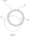
- FIG. 12 shows that a tubular sandwich construction may comprise an outer liner 117 and an inner liner 118.
- An annulus 119 may be formed between the outer liner 117 and the inner liner 118.
- the outer liner 117 is preferably concentric to the inner liner 118.
- the annulus 119 may be filled with concrete. In this way a sandwich element is formed which may be used in the buoyancy element 114 or the body 124 of the centre hub 120.
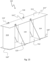
- FIG. 13 shows an isometric projection of the elongated element 110 with an alternative set of stiffening means 115.
- the stiffening means 115 may be arranged singly. By singly it is understood that two stiffening means 115 are not arranged such that they pairwise substantially form an X-shape, it may still be a plurality of stiffening means 115 arranged on the same elongated element 110.
- the stiffening means 115 may be arranged perpendicular to or inclined relative to the elongated members 111, 112, 113. When a plurality of stiffening means 115 are provided, they may be arranged in parallel or with an angle relative to each other.
- This alternative set of stiffening means 115 may be applicable for all elongated elements 110, independent of the number of buoyancy elements 114 and the number of layers.
- Stiffening means 115 may be connected to the edges of the elongated members 11, 112, 113.
- FIG. 14 shows an isometric projection of a floating wind turbine platform 100 comprising three elongated elements 110 (a first elongated element 110, a second elongated element 110 and a third elongated element 110) each comprising one buoyancy element 114.
- the elongated elements 110 may further comprise stiffening means 115.
- the stiffening means 115 may extend from the elongated element 110 to the centre hub 120. Alternatively, the stiffening means 115 may be arranged on the elongated element 110 only.
- FIG. 15 shows an isometric projection of a floating wind turbine platform 100 in a double layered elongated element configuration comprising three elongated elements 110 (a first elongated element 110, a second elongated element 110 and a third elongated element 110) each comprising one buoyancy element 114a,114b in each layer.
- the elongated elements 110 may further comprise stiffening means 115.
- the stiffening means 115 may extend from the elongated element 110 to the centre hub 120. Alternatively, the stiffening means 115 may be arranged on the elongated element 110 only.
- FIG. 16 shows an isometric projection of a double layered elongated element 110 in which the layers are of different lengths.
- the different layers of the elongated element 110 may comprise a different number of buoyancy elements 114a,114b.
- the different layers of the elongated element 110 may comprise a different number of stiffening means 115.
- the different elongated members 111, 112, 113 of the elongated element 110 may have different lengths.
- the stiffening means 115 may be pretensioned with anchor and shoe 116.
- the anchor and shoe 116 can be located inside or outside the elongated members 111, 112, 113.
- the shoe 116 may be located on the outside with the stiffening means 115 protruding the elongated member 111, 112, 113. Outside position of the shoe 116 lead to compressive stress between shoe 1116 and elongated member 111, 112, 113.
- This disclosure provides an innovative approach towards design suited to current wind farm developer requirements in that the simplicity of the geometrical elements enables a reduced set of structural parameters that will accelerate design iterations in a schedule driven environment.
- the gap between the buoyancy elements 114 provides an important parameter for tuning the water resistance versus structural stiffness.
- the diameter of the individual buoyancy elements 114 may be understood as the diameter of the minimum circumcised circle around the cross-sectional shape of said buoyancy elements 114.
- the diameter and height of the individual buoyancy elements 114 are parameters that can be varied in conjunction with the gap parameter to optimize the structural capacity and motion characteristics.
- the floating wind turbine platform 100 may comprise a system for station keeping.
- Said station keeping system may comprise components from the group comprising mooring system and thrusters.
- a mooring system may comprise components from the group comprising synthetic fibre rope, steel chain, steel cable, mass elements, buoyancy elements, damping elements.
- Said mooring system may be anchored to seabed by any type of anchors including suction anchors and torpedoes.
- Triangular and rectangular floating wind turbine platforms 100 may have a mooring system connected to one or several corners of the triangular or rectangular shape. If the tower 200 is arranged in one of the corners, the mooring system may preferably be connected at least to one of the other corners.
- the access systems may be selected from the group comprising sea ladder, boat bumpers, helicopter hoist station and helicopter lading pads.
- the floating wind turbine platform 100 may comprise corrosion protection. Said corrosion protection may be selected from the group comprising of sacrificial anodes, coating and impressed current.
- the floating wind turbine platform 100 may comprise ballast.
- the floating wind turbine platform 100 may comprise an active ballast system.
- Said active ballast system can have autonomous or manual control.
- Said active ballast system can displace ballast to change the trim and draft of the floating wind turbine platform 100.
- the ballast may be static and trim and draft may be changed using temporary ballast pumps.
- the floating wind turbine 1000 may comprise stay cables 500 between the wind turbine tower 200 and the floating wind turbine platform 100.
- the floating wind turbine 1000 may comprise an extension of the central column 400 to a draft below the elongated elements 110 of the floating wind turbine platform 100.
- the floating wind turbine 1000 may comprise stay cables 500 connecting the elongated elements 110 to the central column 400.
- the central column 400 may be utilized for larger water depths to include partly spar buoy effects.
- the material of the floating wind turbine platform 100 may be selected from the group comprising of metal, polymer, composite and ceramic including concrete.
- the floating wind turbine platform 100 may comprise a structural monitoring system.
- Said monitoring system may comprise home-base communication, continuously transmitting the state of all predefined characteristic structural parameters, enabling predictive maintenance, just-in-time operational decisions and detailed learning models for improved design optimization.
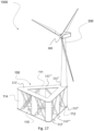
- FIG. 17 shows an isometric projection of a floating wind turbine 1000.
- the floating wind turbine 1000 may comprise a triangular floating wind turbine platform 100 and a horizontal axis turbine 300.
- the triangular floating wind turbine platform 100 may comprise three elongated elements 110 (a first elongated element 110, a second elongated element 110 and a third elongated element 110).
- the elongated elements 110 are illustrated as one layered but may also be multi layered.
- One or all the elongated member 111,112,113 of a triangular floating wind turbine platform 100 may be separate members that are connected during fabrication or made as one piece, e.g. one plate.
- FIG. 17 shows how a horizontal axis turbine 300 may be arranged on a tower 200 arranged on top of the triangular floating wind turbine platform 100.
- the tower 200 is preferably arranged in one of the corners of the triangular floating wind turbine platform 100. Alternatively, the tower may be arranged between two corners of the triangular floating wind turbine platform 100.
- the tower 200 may be arranged on the elongated member 111, at an opposite side of the buoyancy element 114.
- FIG. 17 shows how the tower 200 may extend substantially perpendicularly on the floating wind turbine platform 100. In this way the tower 200 will primarily extend vertically in use.
- FIG. 18 shows an isometric projection of a floating wind turbine 1000.
- the floating wind turbine 1000 may comprise a triangular floating wind turbine platform 100 and a plurality of horizontal axis turbines 300, e.g. two horizontal axis turbines 300.
- the horizontal axis turbines 300 may be arranged in respective corners of the triangular floating wind turbine platform 100.
- FIG. 18 and FIG. 20 show how the tower 200 may extend at an angle relative to the floating wind turbine platform different than 90 degrees.
- two horizontal axis turbines 300 are arranged on the floating wind turbine platform 100, and their towers 200 are angled away from each other, such that the horizontal distance between the horizontal axis turbines 300 are larger than the horizontal distance between the connection point of the towers 200 on the floating wind turbine platform 100.
- a triangular floating wind turbine platform 100 comprising one horizontal axis turbine 300 is illustrated with six buoyancy elements 114.
- a triangular floating wind turbine platform 100 comprising two horizontal axis turbines 300 is illustrated with nine buoyancy elements 114.
- a rectangular floating wind turbine platform 100 comprising one horizontal axis turbine 300 is illustrated with eight buoyancy elements 114.
- a rectangular floating wind turbine platform 100 comprising two horizontal axis turbines 300 is illustrated with twelve buoyancy elements 114.
- connected elongated elements 110 may share one buoyancy element 114.
- FIG. 19 shows an isometric projection of a floating wind turbine 1000 comprising a rectangular floating wind turbine platform 100 and a horizontal axis turbine 300.
- the rectangular floating wind turbine platform 100 comprises four elongated elements 110 (a first elongated element 110, a second elongated element 110, a third elongated element 110 and a fourth elongated element 110).
- the elongated elements 110 have equal lengths and are orthogonally arranged, i.e. as a square. However, the elongated elements 110 may have different lengths, e.g. two and two elongated elements 110 having equal lengths.
- the elongated elements 110 may not be orthogonally arranged, e.g. having two obtuse angles and two acute angles.
- FIG. 19 shows how a horizontal axis turbine 300 may be arranged on a tower 200 arranged on top of the rectangular floating wind turbine platform 100.
- the tower 200 is preferably arranged in one of the corners of the rectangular floating wind turbine platform 100. Alternatively, the tower may be arranged between two corners of the rectangular floating wind turbine platform 100.
- the tower 200 may be arranged on the elongated member 111, at an opposite side of the buoyancy element 114.
- FIG. 19 shows how the tower 200 may extend substantially perpendicularly on the floating wind turbine platform 100. In this way the tower 200 will primarily extend vertically in use.
- FIG. 20 shows an isometric projection of a floating wind turbine 1000.
- the floating wind turbine 1000 may comprise a rectangular floating wind turbine platform 100 and a plurality of horizontal axis turbines 300, e.g. two horizontal axis turbines 300.
- the horizontal axis turbines 300 may be arranged in respective corners of the rectangular floating wind turbine platform 100.
- each elongated element 110 may have a first end and an opposite second end.
- the elongated elements 110 may be arranged in the same plane.
- One of the first end or the second end of each of the elongated elements 110 may be connected to one of the first end or the second end of at least one of the other elongated elements 110, i.e. two and two of the elongated elements 110 may be connected to each other at one of their first or second ends.
- these are connected directly to each other.
- these can be connected to each other indirectly, e.g. via the central hub 120 as illustrated in FIG.3 .
- FIGS. 17 shows how the first elongated element 110 at its first end may be connected to the first end of the second elongated element 110.
- the first elongated element 110 may further be connected at its second end to the first end of a third elongated element 110.
- the second elongated element 110 may at its second end be connected to the second end of the third elongated element 110.
- FIGS. 17-18 it is shown how each of the elongated elements 110 at their ends are directly connected to all the other elongated elements 110.
- each of the elongated elements 110 are connected to another elongated element 110 in both their first and second ends.
- Coupled means any method or device for securing, binding, bonding, fastening, attaching, joining, inserting therein, forming thereon or therein, communicating, or otherwise associating, for example, mechanically, magnetically, electrically, chemically, operably, directly or indirectly with intermediate elements, one or more pieces of members together and may further include without limitation integrally forming one functional member with another in a unity fashion.
- the coupling may occur in any direction, including rotationally.
Landscapes
- Engineering & Computer Science (AREA)
- Combustion & Propulsion (AREA)
- Mechanical Engineering (AREA)
- Chemical & Material Sciences (AREA)
- Ocean & Marine Engineering (AREA)
- Sustainable Energy (AREA)
- Life Sciences & Earth Sciences (AREA)
- General Engineering & Computer Science (AREA)
- Physics & Mathematics (AREA)
- Fluid Mechanics (AREA)
- Sustainable Development (AREA)
- Architecture (AREA)
- Civil Engineering (AREA)
- Structural Engineering (AREA)
- Wind Motors (AREA)
Priority Applications (1)
| Application Number | Priority Date | Filing Date | Title |
|---|---|---|---|
| EP24175755.8A EP4410655A3 (en) | 2019-09-25 | 2020-09-23 | A floating metal platform |
Applications Claiming Priority (4)
| Application Number | Priority Date | Filing Date | Title |
|---|---|---|---|
| NO20191156 | 2019-09-25 | ||
| NO20191179 | 2019-10-02 | ||
| NO20200815A NO345641B2 (en) | 2019-09-25 | 2020-07-10 | Floating Wind Turbine Platform |
| PCT/EP2020/076517 WO2021058531A1 (en) | 2019-09-25 | 2020-09-23 | A floating metal platform |
Related Child Applications (2)
| Application Number | Title | Priority Date | Filing Date |
|---|---|---|---|
| EP24175755.8A Division EP4410655A3 (en) | 2019-09-25 | 2020-09-23 | A floating metal platform |
| EP24175755.8A Division-Into EP4410655A3 (en) | 2019-09-25 | 2020-09-23 | A floating metal platform |
Publications (3)
| Publication Number | Publication Date |
|---|---|
| EP4034455A1 EP4034455A1 (en) | 2022-08-03 |
| EP4034455B1 true EP4034455B1 (en) | 2025-03-05 |
| EP4034455C0 EP4034455C0 (en) | 2025-03-05 |
Family
ID=72644229
Family Applications (2)
| Application Number | Title | Priority Date | Filing Date |
|---|---|---|---|
| EP20780152.3A Active EP4034455B1 (en) | 2019-09-25 | 2020-09-23 | A floating metal platform |
| EP24175755.8A Pending EP4410655A3 (en) | 2019-09-25 | 2020-09-23 | A floating metal platform |
Family Applications After (1)
| Application Number | Title | Priority Date | Filing Date |
|---|---|---|---|
| EP24175755.8A Pending EP4410655A3 (en) | 2019-09-25 | 2020-09-23 | A floating metal platform |
Country Status (11)
| Country | Link |
|---|---|
| US (2) | US12187391B2 (pl) |
| EP (2) | EP4034455B1 (pl) |
| JP (2) | JP7615133B2 (pl) |
| CN (2) | CN114555459B (pl) |
| AU (2) | AU2020355578B2 (pl) |
| BR (1) | BR112022005555A2 (pl) |
| CA (1) | CA3150866A1 (pl) |
| ES (1) | ES3032085T3 (pl) |
| PH (1) | PH12022550618A1 (pl) |
| PL (1) | PL4034455T3 (pl) |
| WO (1) | WO2021058531A1 (pl) |
Families Citing this family (9)
| Publication number | Priority date | Publication date | Assignee | Title |
|---|---|---|---|---|
| KR20220138915A (ko) * | 2021-04-06 | 2022-10-14 | 주식회사 포스코 | 부유식 플랫폼 및 이를 구비하는 부유식 해상 풍력발전장치 |
| BR112023022321A2 (pt) * | 2021-04-29 | 2024-01-16 | Seatrium Sg Pte Ltd | Estrutura flutuante para implantação offshore |
| WO2022231511A1 (en) | 2021-04-29 | 2022-11-03 | Sembcorp Marine Integrated Yard Pte. Ltd. | A buoyant structure for receiving a tower of a wind turbine in offshore deployment |
| US12037092B2 (en) * | 2022-02-12 | 2024-07-16 | Vl Offshore, Llc | Floating offshore foundation including modular components, method for modular assembly of the floating offshore foundation, and a reconfigurable system for the floating offshore foundation |
| JP2024057389A (ja) * | 2022-10-12 | 2024-04-24 | 鹿島建設株式会社 | 浮体式洋上風力発電用下部構造、及び浮体式洋上風力発電用下部構造の施工方法 |
| EP4517084A1 (en) * | 2023-09-04 | 2025-03-05 | TotalEnergies OneTech | Float for offshore wind platforms |
| CN118450388B (zh) * | 2024-04-15 | 2024-12-13 | 中国联合网络通信有限公司广东省分公司 | 一种海洋风机网络全覆盖系统 |
| CN118238958B (zh) * | 2024-05-27 | 2024-08-30 | 南通泰胜蓝岛海洋工程有限公司 | 一种利用驳船合拢导管架与吸力筒的合拢建造工艺 |
| CN118992039A (zh) * | 2024-09-24 | 2024-11-22 | 南方电网电力科技股份有限公司 | 一种漂浮式风机基础平台 |
Family Cites Families (21)
| Publication number | Priority date | Publication date | Assignee | Title |
|---|---|---|---|---|
| GB2365385B (en) | 2000-08-07 | 2004-05-26 | John Michael Pemberton | Total energy extractor |
| GR1005565B (el) * | 2006-02-24 | 2007-06-19 | Ευσταθης πλωτη διαταξη με περιορισμενες ταλαντωσεις | |
| PL2727813T3 (pl) | 2008-04-23 | 2018-07-31 | Principle Power, Inc. | Stabilizowana za pomocą kolumn platforma morska z płytami tłumiącymi typu pułapka wodna i asymetrycznym systemem cumowniczym podtrzymująca morskie turbiny wiatrowe |
| US20120103244A1 (en) | 2010-10-28 | 2012-05-03 | Jin Wang | Truss Cable Semi-submersible Floater for Offshore Wind Turbines and Construction Methods |
| ES2727415T3 (es) | 2010-11-04 | 2019-10-16 | Univ Maine System | Sistema de plataforma y torre de turbina eólica de material compuesto híbrido flotante |
| DE102011052024B4 (de) | 2011-07-21 | 2016-06-23 | Jähnig GmbH Felssicherung und Zaunbau | Schimmendes Bauwerk |
| JP5809069B2 (ja) * | 2012-01-10 | 2015-11-10 | ジャパンマリンユナイテッド株式会社 | スパー型浮体構造物 |
| ES2728170T3 (es) * | 2012-04-13 | 2019-10-22 | Univ Maine System | Plataforma de turbina eólica flotante y método de montaje |
| NO334535B1 (no) * | 2012-08-23 | 2014-03-31 | Olav Olsen As Dr Techn | Flytende, halvt nedsenkbart skrog for opplagring av fortrinnsvis én eller flere vindturbiner |
| EP3382201B1 (en) * | 2013-04-01 | 2020-03-25 | Nippon Steel Corporation | Floating body structure |
| ES2728322T3 (es) | 2013-09-24 | 2019-10-23 | Univ Maine System | Sistema de soporte de turbina eólica flotante |
| PT3102822T (pt) * | 2014-02-06 | 2023-08-18 | Univ Maine System | Método de montagem de uma plataforma de turbina eólica flutuante |
| CN103818523B (zh) * | 2014-03-04 | 2016-09-14 | 新疆金风科技股份有限公司 | 外飘式张力腿浮动风机基础、海上风力发电机及施工方法 |
| ES2776798T3 (es) | 2015-02-24 | 2020-08-03 | Univ Maine System | Método de construcción, ensamblaje, y lanzamiento de una plataforma de turbina eólica flotante |
| CN107709151B (zh) | 2015-04-20 | 2019-12-31 | 缅因大学系统委员会 | 用于漂浮式风力涡轮机平台的壳体 |
| AU2016279059B2 (en) * | 2015-06-19 | 2021-02-04 | Principle Power, Inc | Floating wind turbine platform structure with optimized transfer of wave and wind loads |
| FR3074138B1 (fr) | 2017-11-29 | 2021-08-27 | Saipem Sa | Structure de support flottant pour eolienne offshore et procede d'installation d'une eolienne munie d'une telle structure de support |
| JP2019104420A (ja) | 2017-12-13 | 2019-06-27 | 三井E&S造船株式会社 | 洋上風力発電設備 |
| WO2019143283A1 (en) | 2018-01-19 | 2019-07-25 | Freia Offshore Ab | Floating wind power platform with tension leg device |
| CN108757336A (zh) | 2018-05-03 | 2018-11-06 | 明阳智慧能源集团股份公司 | 一种四立柱带压载半潜式漂浮风机基础 |
| CN109026551B (zh) | 2018-08-27 | 2020-04-14 | 浙江大学 | 基于调谐液柱振荡阻尼器的新型漂浮式风力机基础平台 |
-
2020
- 2020-09-23 CN CN202080067069.XA patent/CN114555459B/zh active Active
- 2020-09-23 AU AU2020355578A patent/AU2020355578B2/en active Active
- 2020-09-23 US US17/763,931 patent/US12187391B2/en active Active
- 2020-09-23 EP EP20780152.3A patent/EP4034455B1/en active Active
- 2020-09-23 JP JP2022518683A patent/JP7615133B2/ja active Active
- 2020-09-23 WO PCT/EP2020/076517 patent/WO2021058531A1/en not_active Ceased
- 2020-09-23 CN CN202410860981.0A patent/CN118579219A/zh active Pending
- 2020-09-23 CA CA3150866A patent/CA3150866A1/en active Pending
- 2020-09-23 ES ES20780152T patent/ES3032085T3/es active Active
- 2020-09-23 PH PH1/2022/550618A patent/PH12022550618A1/en unknown
- 2020-09-23 EP EP24175755.8A patent/EP4410655A3/en active Pending
- 2020-09-23 BR BR112022005555A patent/BR112022005555A2/pt unknown
- 2020-09-23 PL PL20780152.3T patent/PL4034455T3/pl unknown
-
2024
- 2024-10-15 AU AU2024227329A patent/AU2024227329A1/en active Pending
- 2024-11-26 US US18/960,930 patent/US20250083778A1/en active Pending
- 2024-12-27 JP JP2024231667A patent/JP2025036684A/ja active Pending
Also Published As
| Publication number | Publication date |
|---|---|
| JP7615133B2 (ja) | 2025-01-16 |
| CN118579219A (zh) | 2024-09-03 |
| KR20220078621A (ko) | 2022-06-10 |
| BR112022005555A2 (pt) | 2022-08-30 |
| US12187391B2 (en) | 2025-01-07 |
| EP4034455A1 (en) | 2022-08-03 |
| ES3032085T3 (en) | 2025-07-15 |
| JP2022549633A (ja) | 2022-11-28 |
| EP4410655A3 (en) | 2024-10-16 |
| CA3150866A1 (en) | 2021-04-01 |
| US20250083778A1 (en) | 2025-03-13 |
| US20220332395A1 (en) | 2022-10-20 |
| WO2021058531A1 (en) | 2021-04-01 |
| AU2020355578A1 (en) | 2022-05-12 |
| AU2024227329A1 (en) | 2024-10-31 |
| JP2025036684A (ja) | 2025-03-14 |
| EP4410655A2 (en) | 2024-08-07 |
| CN114555459A (zh) | 2022-05-27 |
| PL4034455T3 (pl) | 2025-06-23 |
| PH12022550618A1 (en) | 2022-11-21 |
| AU2020355578B2 (en) | 2024-07-25 |
| EP4034455C0 (en) | 2025-03-05 |
| CN114555459B (zh) | 2024-07-16 |
Similar Documents
| Publication | Publication Date | Title |
|---|---|---|
| AU2020355578B2 (en) | A floating metal platform | |
| US11014637B2 (en) | Motion-attenuated semi-submersible floating-type foundation for supporting a wind power generation system | |
| EP2993345B1 (en) | Floating structure | |
| KR101536959B1 (ko) | 강관주 구조물 및 그의 제조 방법 | |
| US12054228B2 (en) | Floating wind turbine support | |
| EP3960614A1 (en) | Motion-attenuated semi-submersible floating-type foundation for supporting a wind power generation system | |
| US20240309852A1 (en) | Semi-submersible floating platform for offshore wind turbine | |
| WO2019000066A1 (en) | HULL CONSTRUCTION METHODS FOR OFFSHORE STRUCTURES | |
| US12037092B2 (en) | Floating offshore foundation including modular components, method for modular assembly of the floating offshore foundation, and a reconfigurable system for the floating offshore foundation | |
| NO345641B1 (en) | Floating Wind Turbine Platform | |
| WO2023154536A1 (en) | Floating offshore foundation including modular components, method for modular assembly of the floating offshore foundation, and a reconfigurable system for the floating offshore foundation | |
| KR102967107B1 (ko) | 부유식 금속 플랫폼 | |
| CN210621737U (zh) | 一种组合式环筒导管架基础结构 | |
| CN213038418U (zh) | 一种新型海上风电全钢筒型基础结构 | |
| Pettersson | Telescopic tower facilitating installation of≥ 12 MW offshore wind turbines | |
| EP4563814A1 (en) | Semi-submersible platform for supporting wind turbines | |
| CN114348194B (zh) | 悬浮式frp混凝土组合牵索塔式减震平台及其施工方法 | |
| EP4440920A1 (en) | Floating foundation for an offshore wind turbine | |
| CN102897287A (zh) | 重力摆式垂直锚 |
Legal Events
| Date | Code | Title | Description |
|---|---|---|---|
| STAA | Information on the status of an ep patent application or granted ep patent |
Free format text: STATUS: UNKNOWN |
|
| STAA | Information on the status of an ep patent application or granted ep patent |
Free format text: STATUS: THE INTERNATIONAL PUBLICATION HAS BEEN MADE |
|
| TPAC | Observations filed by third parties |
Free format text: ORIGINAL CODE: EPIDOSNTIPA |
|
| PUAI | Public reference made under article 153(3) epc to a published international application that has entered the european phase |
Free format text: ORIGINAL CODE: 0009012 |
|
| STAA | Information on the status of an ep patent application or granted ep patent |
Free format text: STATUS: REQUEST FOR EXAMINATION WAS MADE |
|
| 17P | Request for examination filed |
Effective date: 20220425 |
|
| AK | Designated contracting states |
Kind code of ref document: A1 Designated state(s): AL AT BE BG CH CY CZ DE DK EE ES FI FR GB GR HR HU IE IS IT LI LT LU LV MC MK MT NL NO PL PT RO RS SE SI SK SM TR |
|
| DAV | Request for validation of the european patent (deleted) | ||
| DAX | Request for extension of the european patent (deleted) | ||
| STAA | Information on the status of an ep patent application or granted ep patent |
Free format text: STATUS: EXAMINATION IS IN PROGRESS |
|
| 17Q | First examination report despatched |
Effective date: 20231208 |
|
| GRAP | Despatch of communication of intention to grant a patent |
Free format text: ORIGINAL CODE: EPIDOSNIGR1 |
|
| STAA | Information on the status of an ep patent application or granted ep patent |
Free format text: STATUS: GRANT OF PATENT IS INTENDED |
|
| GRAJ | Information related to disapproval of communication of intention to grant by the applicant or resumption of examination proceedings by the epo deleted |
Free format text: ORIGINAL CODE: EPIDOSDIGR1 |
|
| GRAP | Despatch of communication of intention to grant a patent |
Free format text: ORIGINAL CODE: EPIDOSNIGR1 |
|
| INTG | Intention to grant announced |
Effective date: 20240510 |
|
| INTG | Intention to grant announced |
Effective date: 20240524 |
|
| GRAJ | Information related to disapproval of communication of intention to grant by the applicant or resumption of examination proceedings by the epo deleted |
Free format text: ORIGINAL CODE: EPIDOSDIGR1 |
|
| STAA | Information on the status of an ep patent application or granted ep patent |
Free format text: STATUS: EXAMINATION IS IN PROGRESS |
|
| GRAP | Despatch of communication of intention to grant a patent |
Free format text: ORIGINAL CODE: EPIDOSNIGR1 |
|
| STAA | Information on the status of an ep patent application or granted ep patent |
Free format text: STATUS: GRANT OF PATENT IS INTENDED |
|
| INTC | Intention to grant announced (deleted) | ||
| INTG | Intention to grant announced |
Effective date: 20241028 |
|
| RIN1 | Information on inventor provided before grant (corrected) |
Inventor name: SOENJU, EIVIND |
|
| GRAS | Grant fee paid |
Free format text: ORIGINAL CODE: EPIDOSNIGR3 |
|
| GRAA | (expected) grant |
Free format text: ORIGINAL CODE: 0009210 |
|
| STAA | Information on the status of an ep patent application or granted ep patent |
Free format text: STATUS: THE PATENT HAS BEEN GRANTED |
|
| AK | Designated contracting states |
Kind code of ref document: B1 Designated state(s): AL AT BE BG CH CY CZ DE DK EE ES FI FR GB GR HR HU IE IS IT LI LT LU LV MC MK MT NL NO PL PT RO RS SE SI SK SM TR |
|
| REG | Reference to a national code |
Ref country code: GB Ref legal event code: FG4D |
|
| REG | Reference to a national code |
Ref country code: CH Ref legal event code: EP |
|
| REG | Reference to a national code |
Ref country code: IE Ref legal event code: FG4D |
|
| REG | Reference to a national code |
Ref country code: DE Ref legal event code: R096 Ref document number: 602020047274 Country of ref document: DE |
|
| U01 | Request for unitary effect filed |
Effective date: 20250404 |
|
| U07 | Unitary effect registered |
Designated state(s): AT BE BG DE DK EE FI FR IT LT LU LV MT NL PT RO SE SI Effective date: 20250423 |
|
| PG25 | Lapsed in a contracting state [announced via postgrant information from national office to epo] |
Ref country code: RS Free format text: LAPSE BECAUSE OF FAILURE TO SUBMIT A TRANSLATION OF THE DESCRIPTION OR TO PAY THE FEE WITHIN THE PRESCRIBED TIME-LIMIT Effective date: 20250605 |
|
| PG25 | Lapsed in a contracting state [announced via postgrant information from national office to epo] |
Ref country code: NO Free format text: LAPSE BECAUSE OF FAILURE TO SUBMIT A TRANSLATION OF THE DESCRIPTION OR TO PAY THE FEE WITHIN THE PRESCRIBED TIME-LIMIT Effective date: 20250605 |
|
| REG | Reference to a national code |
Ref country code: ES Ref legal event code: FG2A Ref document number: 3032085 Country of ref document: ES Kind code of ref document: T3 Effective date: 20250715 |
|
| PG25 | Lapsed in a contracting state [announced via postgrant information from national office to epo] |
Ref country code: HR Free format text: LAPSE BECAUSE OF FAILURE TO SUBMIT A TRANSLATION OF THE DESCRIPTION OR TO PAY THE FEE WITHIN THE PRESCRIBED TIME-LIMIT Effective date: 20250305 |
|
| REG | Reference to a national code |
Ref country code: GR Ref legal event code: EP Ref document number: 20250401129 Country of ref document: GR Effective date: 20250707 |
|
| PG25 | Lapsed in a contracting state [announced via postgrant information from national office to epo] |
Ref country code: SM Free format text: LAPSE BECAUSE OF FAILURE TO SUBMIT A TRANSLATION OF THE DESCRIPTION OR TO PAY THE FEE WITHIN THE PRESCRIBED TIME-LIMIT Effective date: 20250305 |
|
| U20 | Renewal fee for the european patent with unitary effect paid |
Year of fee payment: 6 Effective date: 20250903 |
|
| PGFP | Annual fee paid to national office [announced via postgrant information from national office to epo] |
Ref country code: GR Payment date: 20250929 Year of fee payment: 6 |
|
| PGFP | Annual fee paid to national office [announced via postgrant information from national office to epo] |
Ref country code: PL Payment date: 20250905 Year of fee payment: 6 |
|
| PGFP | Annual fee paid to national office [announced via postgrant information from national office to epo] |
Ref country code: GB Payment date: 20250909 Year of fee payment: 6 |
|
| PG25 | Lapsed in a contracting state [announced via postgrant information from national office to epo] |
Ref country code: CZ Free format text: LAPSE BECAUSE OF FAILURE TO SUBMIT A TRANSLATION OF THE DESCRIPTION OR TO PAY THE FEE WITHIN THE PRESCRIBED TIME-LIMIT Effective date: 20250305 |
|
| PGFP | Annual fee paid to national office [announced via postgrant information from national office to epo] |
Ref country code: IE Payment date: 20250909 Year of fee payment: 6 |
|
| PG25 | Lapsed in a contracting state [announced via postgrant information from national office to epo] |
Ref country code: SK Free format text: LAPSE BECAUSE OF FAILURE TO SUBMIT A TRANSLATION OF THE DESCRIPTION OR TO PAY THE FEE WITHIN THE PRESCRIBED TIME-LIMIT Effective date: 20250305 |
|
| PG25 | Lapsed in a contracting state [announced via postgrant information from national office to epo] |
Ref country code: IS Free format text: LAPSE BECAUSE OF FAILURE TO SUBMIT A TRANSLATION OF THE DESCRIPTION OR TO PAY THE FEE WITHIN THE PRESCRIBED TIME-LIMIT Effective date: 20250705 |
|
| PLBE | No opposition filed within time limit |
Free format text: ORIGINAL CODE: 0009261 |
|
| STAA | Information on the status of an ep patent application or granted ep patent |
Free format text: STATUS: NO OPPOSITION FILED WITHIN TIME LIMIT |
|
| REG | Reference to a national code |
Ref country code: CH Ref legal event code: L10 Free format text: ST27 STATUS EVENT CODE: U-0-0-L10-L00 (AS PROVIDED BY THE NATIONAL OFFICE) Effective date: 20260114 |
|
| PGFP | Annual fee paid to national office [announced via postgrant information from national office to epo] |
Ref country code: ES Payment date: 20251010 Year of fee payment: 6 |
|
| 26N | No opposition filed |
Effective date: 20251208 |
|
| REG | Reference to a national code |
Ref country code: CH Ref legal event code: H13 Free format text: ST27 STATUS EVENT CODE: U-0-0-H10-H13 (AS PROVIDED BY THE NATIONAL OFFICE) Effective date: 20260425 |