EP4034426B1 - Improved tiltable footboard system for heavy vehicle - Google Patents
Improved tiltable footboard system for heavy vehicle Download PDFInfo
- Publication number
- EP4034426B1 EP4034426B1 EP20793799.6A EP20793799A EP4034426B1 EP 4034426 B1 EP4034426 B1 EP 4034426B1 EP 20793799 A EP20793799 A EP 20793799A EP 4034426 B1 EP4034426 B1 EP 4034426B1
- Authority
- EP
- European Patent Office
- Prior art keywords
- wall
- bumper
- footboard
- connection
- support
- Prior art date
- Legal status (The legal status is an assumption and is not a legal conclusion. Google has not performed a legal analysis and makes no representation as to the accuracy of the status listed.)
- Active
Links
Images

Classifications
-
- B—PERFORMING OPERATIONS; TRANSPORTING
- B60—VEHICLES IN GENERAL
- B60R—VEHICLES, VEHICLE FITTINGS, OR VEHICLE PARTS, NOT OTHERWISE PROVIDED FOR
- B60R3/00—Arrangements of steps or ladders facilitating access to or on the vehicle, e.g. running-boards
- B60R3/02—Retractable steps or ladders, e.g. movable under shock
-
- B—PERFORMING OPERATIONS; TRANSPORTING
- B60—VEHICLES IN GENERAL
- B60R—VEHICLES, VEHICLE FITTINGS, OR VEHICLE PARTS, NOT OTHERWISE PROVIDED FOR
- B60R19/00—Wheel guards; Radiator guards, e.g. grilles; Obstruction removers; Fittings damping bouncing force in collisions
- B60R19/02—Bumpers, i.e. impact receiving or absorbing members for protecting vehicles or fending off blows from other vehicles or objects
- B60R19/48—Bumpers, i.e. impact receiving or absorbing members for protecting vehicles or fending off blows from other vehicles or objects combined with, or convertible into, other devices or objects, e.g. bumpers combined with road brushes, bumpers convertible into beds
-
- B—PERFORMING OPERATIONS; TRANSPORTING
- B60—VEHICLES IN GENERAL
- B60R—VEHICLES, VEHICLE FITTINGS, OR VEHICLE PARTS, NOT OTHERWISE PROVIDED FOR
- B60R3/00—Arrangements of steps or ladders facilitating access to or on the vehicle, e.g. running-boards
- B60R3/002—Running boards
-
- B—PERFORMING OPERATIONS; TRANSPORTING
- B60—VEHICLES IN GENERAL
- B60R—VEHICLES, VEHICLE FITTINGS, OR VEHICLE PARTS, NOT OTHERWISE PROVIDED FOR
- B60R19/00—Wheel guards; Radiator guards, e.g. grilles; Obstruction removers; Fittings damping bouncing force in collisions
- B60R19/52—Radiator or grille guards ; Radiator grilles
- B60R2019/525—Radiator grilles
Definitions
- the invention relates to a footboard system for a heavy vehicle, in particular to a front tiltable footboard system for a heavy vehicle.
- Tiltable footboards are known, which are integrated in the front part of a heavy vehicle, for example a truck or a bus, and are configured to assume a first closed position, in which they are integrated in the profile of the front bumper of the vehicle, and a second open position, in which they define a step relative to the profile of the front bumper of the vehicle.
- Said step is normally used by the driver of the vehicle in order to access the upper front part of the vehicle, for example the windshield thereof.
- the tiltable footboard is hinged to the front bumper, so that it can move from the aforesaid first position to the aforesaid second position.
- tiltable footboards of this type are disclosed in patent applications IT 1107039 or EP 0885776 .
- footboards are hard to be moved, since they usually are large-sized and are at least partially made of a metal or high-density material.
- the object of the invention is to fulfil the needs discussed above in an economic and optimized fashion.
- Figures 1A and 1B show a front portion of a heavy vehicle 1, for example a truck, comprising, as it is known, a cabin 2 and provided with a front bumper 3.
- the front bumper 3 comprises a tiltable footboard system 4, which is configured to assume a first closed position, in which it is integrated in the front bumper 3, namely the profile of the footboard system 4 is continuous with the profile of the remaining portions of the bumper 3, and a second open position, in which it defines a step designed to support the weight of a driver of the vehicle.
- the tiltable footboard system 4 comprises first connection means 6 and second connection means 6 arranged on the sides, on the left and on the right, of the wall 5.
- first connection means 6 and second connection means 6 arranged on the sides, on the left and on the right, of the wall 5.
- second connection means 6 arranged on the sides, on the left and on the right, of the wall 5.
- connection means 6 comprise a support bracket 7, which is rigidly carried by the frame of the vehicle, for example by the front bumper 3, a connection arm 8, which comprises a first end 8a rigidly connected to the wall 5 and a second end 8b cooperating with the support bracket 7, and elastic means 9, which are interposed between the support bracket 7 and the connection arm 8 and are configured to transmit a return force to the connection arm and, hence, to the wall 5 so as to cause said wall 5 to return towards the bumper 2. Therefore, said force tends to keep the wall 5 closed in the bumper 2 in its closed configuration and to damp the opening thereof, as described more in detail below.
- connection arm 8 advantageously has a gooseneck development and comprises a first substantially rectilinear portion 8', which defines, at its end, the first end 8a fixed to the wall 5, for example by means of threaded elements (which are not shown), and a second substantially rectilinear portion 8'', which has a longitudinal axis perpendicular and skewed relative to the longitudinal axis of the first portion 8' and defines the second end 8b cooperating with the support bracket 7.
- connection arm 8 further comprises a third portion 8" ', which is configured to connect said first and second portions 8', 8'' to one another.
- the third portion 8′′′ has a curved shape, in the case described herein the shape of a quarter of a circle, configured to define the 90° angle between the first and the second portions 8', 8".
- the first portion 8' substantially has a greater longitudinal development than the second portion 8".
- the support bracket 7 comprises a lower portion 7a and an upper portion 7b, which are vertically spaced apart from one another.
- the lower portion 7a has a "C"-shaped cross section and is configured to wrap the second portion 8'' of the connection arm 8 on at least two sides, for example a rear side and a lateral side. At least the rear side is advantageously configured to cooperate in contact with the second portion 8", as better explained below.
- the shape and the distance of the lower portion 7a relative to the second portion 8" are such that, in the open position, it cooperates in contact with the latter in order to prevent the wall 5 from being moved any further relative to the bumper 3 and, when the wall 5 needs to be moved to the closed position, it does not forbid the movement of the third portion 8′′′ and of the first portion 8' relative to it.
- the elastic means 9 are interposed between the support bracket 7 and the connection element 8 and are configured to generate a relative force between the two of them, which allows the wall 5 to be opened in a damped manner and be held in the closed position.
- the elastic means 9 are interposed between the upper portion 7b of the support bracket 7 and the first portion 8', in particular at an end 8c of the first portion 8' opposite the first end 8a, namely close to the connection of the first portion to the third portion 8′′′.
- the elastic means 9 advantageously comprise an air spring 11, which is connected to the support 7 and to the arm 8 by means of a first and a second movable connections 12a, 12b.
- the air spring 11 comprises a cylinder 13 and a rod 14.
- the cylinder 13 is connected to the upper portion 7b of the support bracket 7 by means of the first movable connection 12a and the rod 14 is connected to the end 8c of the arm 8 by means of the second movable connection 12b.
- At least one of the movable connections 12a, 12b advantageously comprises a tolerance recovery device 15, which is configured to allow for the fitting of the air spring 11 in case there are differences from the design values during the mounting phase.
- the second movable connection 12b comprises a known hinge 16
- the first movable connection 12a comprises a known hinge 16 and a tolerance recovery device 15 as described above.
- the tolerance recovery device 15 comprises a slot 17, which is configured to house, on the inside, the pin of the hinge 16. In this way, if there are tolerance problems, the slot 16 allows the pin to be housed inside its entire extension, thus allowing possible tolerance differences due to the assembly to be compensated.
- the tolerance recovery device 15 comprises a pair of slots 17 obtained in a pair of walls 18 extending from the cylinder 13, in the direction of its longitudinal axis, towards the upper portion 7b of the support bracket 7 on both sides of a coupling portion 7c, which defines a hole (not shown) designed to house the pin of the hinge 16 so that it is free to rotate.
- the slots 17 preferably extend in length in the direction of the longitudinal axis of the spring 11 and, therefore, the pin of the hinge 16 can cooperate with the walls 18 in any point along said longitudinal extension of the slots 17, thus compensating, as mentioned above, possible tolerance differences due to the assembly of the footboard system 4.
- the wall 5 is open, the air spring 11 reaches it maximum extension, namely the rod 14 is in the maximum position outside the cylinder 13 and, given the point of connection in the end portion 8c, the weight of the wall 5 does not allow it to return, unless there is an external intervention. Therefore, the step defined by the footboard is stable in its position.
- the footboard system 4 shown herein allows the wall 5 integrated in the bumper 2 to be opened in a damped and safe manner and, at the same time, allows the wall 5 to be kept in the bumper 2 when it is in the closed position.
- the particular geometry described herein has the advantage of being particularly compact and, hence, of reducing the axial dimensions of the bumper 2.
- gas spring 11 as elastic means 9 ensures that a proper force is provided in a compact and economic fashion.
- the position of the fixing of the hinges 16, together with the geometry of the arms 8, allows the arms of the force provided by the elastic means 9 to be exploited, thus having to apply a low-value force in order to keep the wall 5 adherent to the bumper 2 and damp the downward movement thereof.
- footboard system 4 according to the invention can be subjected to changes and variants, which, though, do not go beyond the scope of protection set forth in the appended claims.
- the elastic means 9 or the tolerance recovery device 15 can be replaced by devices having the same functionality.
Landscapes
- Engineering & Computer Science (AREA)
- Mechanical Engineering (AREA)
- Vehicle Step Arrangements And Article Storage (AREA)
- Vehicle Body Suspensions (AREA)
Description
- The invention relates to a footboard system for a heavy vehicle, in particular to a front tiltable footboard system for a heavy vehicle.
- Tiltable footboards are known, which are integrated in the front part of a heavy vehicle, for example a truck or a bus, and are configured to assume a first closed position, in which they are integrated in the profile of the front bumper of the vehicle, and a second open position, in which they define a step relative to the profile of the front bumper of the vehicle.
- Said step is normally used by the driver of the vehicle in order to access the upper front part of the vehicle, for example the windshield thereof. In particular, the tiltable footboard is hinged to the front bumper, so that it can move from the aforesaid first position to the aforesaid second position.
- Examples of tiltable footboards of this type are disclosed in patent applications
IT 1107039 EP 0885776 . - However, these footboards are hard to be moved, since they usually are large-sized and are at least partially made of a metal or high-density material.
- Hence, operators must make a significant physical effort in order to open and close the footboard. Furthermore, if the footboard slips from the hands of the operator, the latter would risk being hit by the footboard itself.
- Other known footboards are known by documents
CN1663847 A , which shows the preamble ofclaim 1,US2013154229 A1 ,US2008231076 A1 ,CN201405813 Y ,US4159122 A orDE102016011627 A1 . - Therefore, known tiltable footboards need to be improved so as to increase the comfort perceived during their use as well as their safety.
- The object of the invention is to fulfil the needs discussed above in an economic and optimized fashion.
- The aforesaid object is reached by means of a tiltable footboard system and a vehicle according to the appended claims.
- The invention will be best understood upon perusal of the following detailed description of a preferred embodiment, which is provided by way of non-limiting example, with reference to the accompanying drawings, wherein:
-
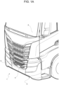
figure 1A is a perspective view showing a front portion, in particular a front bumper, of a heavy vehicle comprising a footboard system according to the invention in a first operating step, -
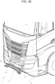
figure 1B is a perspective view showing the footboard system offigure 1A in a second operating step; -
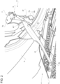
figure 2 is a perspective view showing a portion of the footboard system according to the invention; and -
figure 3 is an enlarged perspective view of a portion offigure 2 . -
Figures 1A and1B show a front portion of aheavy vehicle 1, for example a truck, comprising, as it is known, acabin 2 and provided with afront bumper 3. - The
front bumper 3 comprises atiltable footboard system 4, which is configured to assume a first closed position, in which it is integrated in thefront bumper 3, namely the profile of thefootboard system 4 is continuous with the profile of the remaining portions of thebumper 3, and a second open position, in which it defines a step designed to support the weight of a driver of the vehicle. - Therefore, in particular, the
tiltable footboard system 4 comprises awall 5 having an outer profile that, when it is in the closed position, is continuous with the profile of thefront bumper 3. Thewall 5 is preferably made of aluminium. In particular, in the case descrybed herein, thewall 5 is the central part of the bumper of thecabin 2. - The
tiltable footboard system 4 further comprises mechanical connection means 6 between thewall 5 and a portion that is fixed to a frame of thevehicle 1, for example thebumper 3. Said connection means 6 allow thewall 5 to shift between the aforesaid closed and open positions. - In the embodiment described herein, the
tiltable footboard system 4 comprises first connection means 6 and second connection means 6 arranged on the sides, on the left and on the right, of thewall 5. Hereinafter only one of them will be described for the sake of brevity, since they are identical. - According to the invention, the connection means 6 comprise a
support bracket 7, which is rigidly carried by the frame of the vehicle, for example by thefront bumper 3, aconnection arm 8, which comprises afirst end 8a rigidly connected to thewall 5 and asecond end 8b cooperating with thesupport bracket 7, andelastic means 9, which are interposed between thesupport bracket 7 and theconnection arm 8 and are configured to transmit a return force to the connection arm and, hence, to thewall 5 so as to cause saidwall 5 to return towards thebumper 2. Therefore, said force tends to keep thewall 5 closed in thebumper 2 in its closed configuration and to damp the opening thereof, as described more in detail below. - With reference to
figure 2 , theconnection arm 8 advantageously has a gooseneck development and comprises a first substantially rectilinear portion 8', which defines, at its end, thefirst end 8a fixed to thewall 5, for example by means of threaded elements (which are not shown), and a second substantially rectilinear portion 8'', which has a longitudinal axis perpendicular and skewed relative to the longitudinal axis of the first portion 8' and defines thesecond end 8b cooperating with thesupport bracket 7. - The
connection arm 8 further comprises athird portion 8" ', which is configured to connect said first and second portions 8', 8'' to one another. In particular, thethird portion 8‴ has a curved shape, in the case described herein the shape of a quarter of a circle, configured to define the 90° angle between the first and thesecond portions 8', 8". The first portion 8' substantially has a greater longitudinal development than thesecond portion 8". - The
support bracket 7 comprises alower portion 7a and anupper portion 7b, which are vertically spaced apart from one another. In particular, thelower portion 7a has a "C"-shaped cross section and is configured to wrap the second portion 8'' of theconnection arm 8 on at least two sides, for example a rear side and a lateral side. At least the rear side is advantageously configured to cooperate in contact with thesecond portion 8", as better explained below. - In particular, the shape and the distance of the
lower portion 7a relative to thesecond portion 8" are such that, in the open position, it cooperates in contact with the latter in order to prevent thewall 5 from being moved any further relative to thebumper 3 and, when thewall 5 needs to be moved to the closed position, it does not forbid the movement of thethird portion 8‴ and of the first portion 8' relative to it. - The elastic means 9, as mentioned above, are interposed between the
support bracket 7 and theconnection element 8 and are configured to generate a relative force between the two of them, which allows thewall 5 to be opened in a damped manner and be held in the closed position. As a consequence, in order to optimize the arms of action of the force, theelastic means 9 are interposed between theupper portion 7b of thesupport bracket 7 and the first portion 8', in particular at an end 8c of the first portion 8' opposite thefirst end 8a, namely close to the connection of the first portion to thethird portion 8‴. - The elastic means 9 advantageously comprise an
air spring 11, which is connected to thesupport 7 and to thearm 8 by means of a first and a secondmovable connections air spring 11 comprises acylinder 13 and arod 14. In the case described herein, thecylinder 13 is connected to theupper portion 7b of thesupport bracket 7 by means of the firstmovable connection 12a and therod 14 is connected to the end 8c of thearm 8 by means of the secondmovable connection 12b. - At least one of the
movable connections tolerance recovery device 15, which is configured to allow for the fitting of theair spring 11 in case there are differences from the design values during the mounting phase. In the case described herein, the secondmovable connection 12b comprises a knownhinge 16, whereas the firstmovable connection 12a comprises a knownhinge 16 and atolerance recovery device 15 as described above. - In particular, the
tolerance recovery device 15 comprises aslot 17, which is configured to house, on the inside, the pin of thehinge 16. In this way, if there are tolerance problems, theslot 16 allows the pin to be housed inside its entire extension, thus allowing possible tolerance differences due to the assembly to be compensated. - In the case described herein, the
tolerance recovery device 15 comprises a pair ofslots 17 obtained in a pair ofwalls 18 extending from thecylinder 13, in the direction of its longitudinal axis, towards theupper portion 7b of thesupport bracket 7 on both sides of acoupling portion 7c, which defines a hole (not shown) designed to house the pin of thehinge 16 so that it is free to rotate. - The
slots 17 preferably extend in length in the direction of the longitudinal axis of thespring 11 and, therefore, the pin of thehinge 16 can cooperate with thewalls 18 in any point along said longitudinal extension of theslots 17, thus compensating, as mentioned above, possible tolerance differences due to the assembly of thefootboard system 4. - The embodiment of the
footboard system 4 described above works as follows. - In the condition of
figure 1A , thewall 5 is enclosed in thebumper 3, in continuity with the shape defined by the latter. In this condition, theair spring 11 reaches its minimum extension, namely therod 14 is in the maximum retracted position inside thecylinder 13 and provides a return force suited to hold thearm 8 in the closed position. In particular, said return force is of approximately 110 N. Given the point of connection in the end portion 8c and the fact that thewall 5, when it is closed, is in a substantially vertical position, the force provided by theair spring 11 is sufficient to keep thewall 5 firmly closed in thebumper 3, unless there is an external intervention. - In the condition of
figure 1B , thewall 5 is open, theair spring 11 reaches it maximum extension, namely therod 14 is in the maximum position outside thecylinder 13 and, given the point of connection in the end portion 8c, the weight of thewall 5 does not allow it to return, unless there is an external intervention. Therefore, the step defined by the footboard is stable in its position. - When operators want to shift from the closed position to the open position, they simply need to apply a force along an upper edge of the
wall 5 towards the outside relative to thebumper 3. Given the extent of the closing force of thespring 11 and the fact that, by opening, the weight force of thewall 5 helps operators, the latter never excessively interferes with the opening of thewall 5, but simply damps the movement thereof. In this way, the opening is safe, namely sudden opening movements of thewall 5 are avoided. - On the contrary, when operators want to shift from the open position to the closed position, they simply need to apply a force along an upper edge of the
wall 5 towards thebumper 3. During this operation, on the one hand, there is a return force that causes therod 14 to return inside thecylinder 13 and, on the other hand, the weight force tends to decrease its arm of action and, therefore, decreases its tilting effect. In this way, the opening is facilitated by the return of theair spring 11. - Owing to the above, the advantages of a
footboard system 4 according to the invention are evident. - The
footboard system 4 shown herein allows thewall 5 integrated in thebumper 2 to be opened in a damped and safe manner and, at the same time, allows thewall 5 to be kept in thebumper 2 when it is in the closed position. - The use of a pair of
gooseneck arms 8, namely comprising theportions 8', 8" and 8‴ described above, with thesupport 7 allows users to obtain, without further hinges, the controlled rotation of thewall 5 relative to thebumper 2. - The particular geometry described herein has the advantage of being particularly compact and, hence, of reducing the axial dimensions of the
bumper 2. - The use of a
gas spring 11 aselastic means 9 ensures that a proper force is provided in a compact and economic fashion. - The
tolerance recovery device 15 allows for the compensation, during building or maintenance, of possible tolerances in the mounting of thegas spring 11. - In particular, the position of the fixing of the
hinges 16, together with the geometry of thearms 8, allows the arms of the force provided by theelastic means 9 to be exploited, thus having to apply a low-value force in order to keep thewall 5 adherent to thebumper 2 and damp the downward movement thereof. - Finally, the
footboard system 4 according to the invention can be subjected to changes and variants, which, though, do not go beyond the scope of protection set forth in the appended claims. - For instance, it is clear that the shape of
wall 5, of thesupport 7 or of thearms 8 can be different. Moreover, the number ofarms 8 can be changed. - Furthermore, the
elastic means 9 or thetolerance recovery device 15 can be replaced by devices having the same functionality.
Claims (12)
- A footboard system (4) for a bumper (2) of a heavy vehicle, said footboard system (4) comprising a wall (5) and at least one mechanical connection means (6) between said wall (5) and a support (7), which is fixed relative to said bumper, said mechanical connection means (6) being configured to move said wall (5) from a first condition, in which it defines a step, to a second position, in which it is integrated in said bumper (2), said footboard system (4) comprising elastic means (9), which are interposed between said support (7) and said wall (5) and are configured to provide a return force to cause said wall (5) to return towards said bumper (2),wherein said at least one mechanical connection means (6) comprises a connection arm (8) comprising a first end (8a) connected to said wall (5) and a second end (8b) cooperating in contact with said support (7),characterized in that said support comprises an upper portion (7b) and a lower portion (7a) spaced from each other, said lower portion (7a) cooperating in contact with said second end (8b), said lower portion (7b) wraps, at least at the back and on the side, said second end (8b), said second end (8b) cooperating in contact with at least said rear wrapping of said lower portion (7b).
- The system according to claim 1, wherein said connection arm (8) comprises a first rectilinear portion defining said first end (8a) and a second rectilinear portion (8') defining said second end (8b), said first portion having a greater longitudinal development than said second rectilinear portion (8").
- The system according to claim 2, wherein said connection arm (8) comprises a third portion (8‴) joining said first and second rectilinear portions (8', 8"), said third portion (8‴) and said first rectilinear portion (8') not cooperating in contact with said support (7) in any operating condition of said wall (5).
- The system according to claim 2 or 3, wherein the longitudinal axes of said first and said second rectilinear portions (8', 8") are perpendicular to each other and skewed.
- The system according to one of the preceding claims, wherein said elastic means (9) comprise a gas spring (11).
- The system according to claim 5, wherein one out of a rod (14) and a cylinder (13) of said gas spring (11) is connected to said mechanical connection means (6) by means of a first movable connection (12b) and the other of said rod (14) and said cylinder (13) is connected to said support (7) by means of a second movable connection (12a).
- The system according to claim 6, wherein said movable connections (12a 12b) comprise a hinge (16).
- The system according to claim 6 or 7, wherein at least one of said movable connections (12a, 12b) comprises a tolerance recovery device (15).
- The system according to claim 8, wherein said tolerance recovery device (15) comprises a slot (17) defined in a wall (18) integral to one out of said cylinder (13) and said rod (14) and defining a seat for said movable connections (12a, 12b).
- The system according to one of the claims from 7 to 9, when depending on one of the claims 3 to 5, wherein said movable connection (12b) between said gas spring (11) and said connection arm (8) is provided on said first portion (8') .
- The system according to one of the claims from 7 to 10, when depending on one of the claims 4 or 5, wherein said movable connection (12b) between said gas spring (11) and said connection arm (8) is provided on said first portion (8') in the vicinity of said third portion (8‴).
- A vehicle comprising a bumper (2) and a tiltable footboard system (4) according to one of the preceding claims.
Applications Claiming Priority (2)
| Application Number | Priority Date | Filing Date | Title |
|---|---|---|---|
| IT102019000017003A IT201900017003A1 (en) | 2019-09-23 | 2019-09-23 | IMPROVED TIPPING PLATFORM SYSTEM FOR HEAVY VEHICLE |
| PCT/IB2020/058884 WO2021059156A1 (en) | 2019-09-23 | 2020-09-23 | Improved tiltable footboard system for heavy vehicle |
Publications (3)
| Publication Number | Publication Date |
|---|---|
| EP4034426A1 EP4034426A1 (en) | 2022-08-03 |
| EP4034426C0 EP4034426C0 (en) | 2023-11-01 |
| EP4034426B1 true EP4034426B1 (en) | 2023-11-01 |
Family
ID=69469017
Family Applications (1)
| Application Number | Title | Priority Date | Filing Date |
|---|---|---|---|
| EP20793799.6A Active EP4034426B1 (en) | 2019-09-23 | 2020-09-23 | Improved tiltable footboard system for heavy vehicle |
Country Status (4)
| Country | Link |
|---|---|
| EP (1) | EP4034426B1 (en) |
| KR (1) | KR102836108B1 (en) |
| IT (1) | IT201900017003A1 (en) |
| WO (1) | WO2021059156A1 (en) |
Families Citing this family (2)
| Publication number | Priority date | Publication date | Assignee | Title |
|---|---|---|---|---|
| EP4177110B1 (en) * | 2021-11-03 | 2024-10-09 | Volvo Truck Corporation | A foldable front step and a vehicle |
| CN116572880A (en) * | 2023-05-29 | 2023-08-11 | 东风华神汽车有限公司 | Reversible middle net assembly and vehicle |
Citations (10)
| Publication number | Priority date | Publication date | Assignee | Title |
|---|---|---|---|---|
| US3980319A (en) | 1975-07-23 | 1976-09-14 | R And L Accessories, Inc. | Folding step for high ground clearance vehicles |
| US4159122A (en) | 1978-04-03 | 1979-06-26 | Stevens Kenneth E | Folding step for vehicle |
| JPS6011850U (en) | 1983-07-05 | 1985-01-26 | 三菱自動車工業株式会社 | Cabover vehicle front step device |
| US4750753A (en) | 1984-08-15 | 1988-06-14 | Dezern Morris L | Bumper mounted folding step assembly |
| SE505097C2 (en) | 1993-12-29 | 1997-06-23 | Scania Cv Ab | Foot step arrangement for vehicle door |
| CN1663847A (en) | 2005-03-30 | 2005-09-07 | 三一汽车制造有限公司 | Automobile bumper with turning pedal mechanism |
| JP2007176186A (en) * | 2005-12-26 | 2007-07-12 | Mitsubishi Fuso Truck & Bus Corp | Vehicular step device |
| US20130154229A1 (en) | 2011-12-14 | 2013-06-20 | Hyundai Motor Company | Bumper step for heavy-duty truck |
| DE202017001312U1 (en) | 2017-03-10 | 2017-11-16 | Alphadynamik GmbH & Co. KG | Sprung rear step with customizable kinetics for commercial vehicles of the automotive industry |
| DE102018007969A1 (en) | 2018-10-09 | 2019-03-28 | Daimler Ag | Boss central unit and vehicle with a bumper central unit |
Family Cites Families (6)
| Publication number | Priority date | Publication date | Assignee | Title |
|---|---|---|---|---|
| DE2705849C2 (en) | 1977-02-11 | 1985-11-14 | Karl Kässbohrer Fahrzeugwerke GmbH, 7900 Ulm | Front area of a vehicle with a bumper |
| JPH0558509U (en) * | 1992-01-17 | 1993-08-03 | 日野自動車工業株式会社 | Vehicle bumper |
| DE69715164T2 (en) | 1997-06-19 | 2003-01-09 | Volvo Lastvagnar Ab, Gothenburg | Bumper with step |
| US7703784B2 (en) * | 2007-03-21 | 2010-04-27 | Nissan Technical Center North America, Inc. | Vehicle structure |
| CN201405813Y (en) * | 2009-05-27 | 2010-02-17 | 安徽华菱汽车股份有限公司 | Bumper assembly of heavy truck |
| SE540077C2 (en) * | 2015-10-08 | 2018-03-13 | Scania Cv Ab | Front hatch with integrated foot step |
-
2019
- 2019-09-23 IT IT102019000017003A patent/IT201900017003A1/en unknown
-
2020
- 2020-09-23 KR KR1020227013648A patent/KR102836108B1/en active Active
- 2020-09-23 EP EP20793799.6A patent/EP4034426B1/en active Active
- 2020-09-23 WO PCT/IB2020/058884 patent/WO2021059156A1/en not_active Ceased
Patent Citations (10)
| Publication number | Priority date | Publication date | Assignee | Title |
|---|---|---|---|---|
| US3980319A (en) | 1975-07-23 | 1976-09-14 | R And L Accessories, Inc. | Folding step for high ground clearance vehicles |
| US4159122A (en) | 1978-04-03 | 1979-06-26 | Stevens Kenneth E | Folding step for vehicle |
| JPS6011850U (en) | 1983-07-05 | 1985-01-26 | 三菱自動車工業株式会社 | Cabover vehicle front step device |
| US4750753A (en) | 1984-08-15 | 1988-06-14 | Dezern Morris L | Bumper mounted folding step assembly |
| SE505097C2 (en) | 1993-12-29 | 1997-06-23 | Scania Cv Ab | Foot step arrangement for vehicle door |
| CN1663847A (en) | 2005-03-30 | 2005-09-07 | 三一汽车制造有限公司 | Automobile bumper with turning pedal mechanism |
| JP2007176186A (en) * | 2005-12-26 | 2007-07-12 | Mitsubishi Fuso Truck & Bus Corp | Vehicular step device |
| US20130154229A1 (en) | 2011-12-14 | 2013-06-20 | Hyundai Motor Company | Bumper step for heavy-duty truck |
| DE202017001312U1 (en) | 2017-03-10 | 2017-11-16 | Alphadynamik GmbH & Co. KG | Sprung rear step with customizable kinetics for commercial vehicles of the automotive industry |
| DE102018007969A1 (en) | 2018-10-09 | 2019-03-28 | Daimler Ag | Boss central unit and vehicle with a bumper central unit |
Also Published As
| Publication number | Publication date |
|---|---|
| EP4034426C0 (en) | 2023-11-01 |
| IT201900017003A1 (en) | 2021-03-23 |
| EP4034426A1 (en) | 2022-08-03 |
| KR20220069072A (en) | 2022-05-26 |
| BR112022005328A2 (en) | 2022-06-14 |
| WO2021059156A1 (en) | 2021-04-01 |
| KR102836108B1 (en) | 2025-07-18 |
Similar Documents
| Publication | Publication Date | Title |
|---|---|---|
| EP4034426B1 (en) | Improved tiltable footboard system for heavy vehicle | |
| US5988679A (en) | Device for adjusting the length, and/or height, and/or tilt of a steering column of a motor vehicle | |
| US11585133B2 (en) | Hinge device | |
| WO2017074741A1 (en) | Truck bed extension apparatus | |
| US6419293B1 (en) | Torsion bar for a door lid | |
| US6447043B1 (en) | Vehicle closure assembly with hinge | |
| EP3406834A1 (en) | Hinge mechanism and furniture | |
| CN112211519A (en) | Closure panel balancing mechanism with threaded connection | |
| US20130000941A1 (en) | Power feeding wiring structure | |
| US20170241179A1 (en) | Door support structure of automotive vehicle | |
| KR102900140B1 (en) | Glovebox | |
| KR100595847B1 (en) | Inner wall cover of the gangway bellows between two articulated vehicle or vehicle parts | |
| KR20180094557A (en) | Apparatus for covering load box in truck | |
| CN114150957A (en) | hood hinge structure | |
| EP2289721B1 (en) | Door for a cabin of an industrial vehicle and cabin comprising such door | |
| WO2007123447A1 (en) | An access system for a vehicle | |
| KR102032239B1 (en) | Armrest hinge of car | |
| KR101802639B1 (en) | A Stopper hinge for heavy equipment | |
| EP3872287B1 (en) | Door opening/closing device and hinge | |
| KR102390644B1 (en) | Door system for protecting finger | |
| EP4034425B1 (en) | Improved tiltable footboard system for heavy vehicle | |
| BR112022005328B1 (en) | Enhanced tilting running board system for heavy vehicles. | |
| WO2009018866A1 (en) | Hinge structure for the articulation of a tiltable shutter to a load-bearing side wall of the body of a furniture piece | |
| KR102752853B1 (en) | Active hood hinge for vehicle | |
| JP4868137B2 (en) | Opening and closing mechanism for vehicle door |
Legal Events
| Date | Code | Title | Description |
|---|---|---|---|
| STAA | Information on the status of an ep patent application or granted ep patent |
Free format text: STATUS: UNKNOWN |
|
| STAA | Information on the status of an ep patent application or granted ep patent |
Free format text: STATUS: THE INTERNATIONAL PUBLICATION HAS BEEN MADE |
|
| PUAI | Public reference made under article 153(3) epc to a published international application that has entered the european phase |
Free format text: ORIGINAL CODE: 0009012 |
|
| STAA | Information on the status of an ep patent application or granted ep patent |
Free format text: STATUS: REQUEST FOR EXAMINATION WAS MADE |
|
| 17P | Request for examination filed |
Effective date: 20220317 |
|
| AK | Designated contracting states |
Kind code of ref document: A1 Designated state(s): AL AT BE BG CH CY CZ DE DK EE ES FI FR GB GR HR HU IE IS IT LI LT LU LV MC MK MT NL NO PL PT RO RS SE SI SK SM TR |
|
| DAV | Request for validation of the european patent (deleted) | ||
| DAX | Request for extension of the european patent (deleted) | ||
| GRAP | Despatch of communication of intention to grant a patent |
Free format text: ORIGINAL CODE: EPIDOSNIGR1 |
|
| STAA | Information on the status of an ep patent application or granted ep patent |
Free format text: STATUS: GRANT OF PATENT IS INTENDED |
|
| INTG | Intention to grant announced |
Effective date: 20230428 |
|
| GRAS | Grant fee paid |
Free format text: ORIGINAL CODE: EPIDOSNIGR3 |
|
| GRAA | (expected) grant |
Free format text: ORIGINAL CODE: 0009210 |
|
| STAA | Information on the status of an ep patent application or granted ep patent |
Free format text: STATUS: THE PATENT HAS BEEN GRANTED |
|
| AK | Designated contracting states |
Kind code of ref document: B1 Designated state(s): AL AT BE BG CH CY CZ DE DK EE ES FI FR GB GR HR HU IE IS IT LI LT LU LV MC MK MT NL NO PL PT RO RS SE SI SK SM TR |
|
| REG | Reference to a national code |
Ref country code: GB Ref legal event code: FG4D |
|
| REG | Reference to a national code |
Ref country code: CH Ref legal event code: EP |
|
| REG | Reference to a national code |
Ref country code: IE Ref legal event code: FG4D |
|
| REG | Reference to a national code |
Ref country code: DE Ref legal event code: R096 Ref document number: 602020020387 Country of ref document: DE |
|
| U01 | Request for unitary effect filed |
Effective date: 20231116 |
|
| U07 | Unitary effect registered |
Designated state(s): AT BE BG DE DK EE FI FR IT LT LU LV MT NL PT SE SI Effective date: 20231122 |
|
| PG25 | Lapsed in a contracting state [announced via postgrant information from national office to epo] |
Ref country code: GR Free format text: LAPSE BECAUSE OF FAILURE TO SUBMIT A TRANSLATION OF THE DESCRIPTION OR TO PAY THE FEE WITHIN THE PRESCRIBED TIME-LIMIT Effective date: 20240202 |
|
| PG25 | Lapsed in a contracting state [announced via postgrant information from national office to epo] |
Ref country code: IS Free format text: LAPSE BECAUSE OF FAILURE TO SUBMIT A TRANSLATION OF THE DESCRIPTION OR TO PAY THE FEE WITHIN THE PRESCRIBED TIME-LIMIT Effective date: 20240301 |
|
| PG25 | Lapsed in a contracting state [announced via postgrant information from national office to epo] |
Ref country code: ES Free format text: LAPSE BECAUSE OF FAILURE TO SUBMIT A TRANSLATION OF THE DESCRIPTION OR TO PAY THE FEE WITHIN THE PRESCRIBED TIME-LIMIT Effective date: 20231101 |
|
| PG25 | Lapsed in a contracting state [announced via postgrant information from national office to epo] |
Ref country code: IS Free format text: LAPSE BECAUSE OF FAILURE TO SUBMIT A TRANSLATION OF THE DESCRIPTION OR TO PAY THE FEE WITHIN THE PRESCRIBED TIME-LIMIT Effective date: 20240301 Ref country code: GR Free format text: LAPSE BECAUSE OF FAILURE TO SUBMIT A TRANSLATION OF THE DESCRIPTION OR TO PAY THE FEE WITHIN THE PRESCRIBED TIME-LIMIT Effective date: 20240202 Ref country code: ES Free format text: LAPSE BECAUSE OF FAILURE TO SUBMIT A TRANSLATION OF THE DESCRIPTION OR TO PAY THE FEE WITHIN THE PRESCRIBED TIME-LIMIT Effective date: 20231101 |
|
| PG25 | Lapsed in a contracting state [announced via postgrant information from national office to epo] |
Ref country code: RS Free format text: LAPSE BECAUSE OF FAILURE TO SUBMIT A TRANSLATION OF THE DESCRIPTION OR TO PAY THE FEE WITHIN THE PRESCRIBED TIME-LIMIT Effective date: 20231101 Ref country code: PL Free format text: LAPSE BECAUSE OF FAILURE TO SUBMIT A TRANSLATION OF THE DESCRIPTION OR TO PAY THE FEE WITHIN THE PRESCRIBED TIME-LIMIT Effective date: 20231101 Ref country code: NO Free format text: LAPSE BECAUSE OF FAILURE TO SUBMIT A TRANSLATION OF THE DESCRIPTION OR TO PAY THE FEE WITHIN THE PRESCRIBED TIME-LIMIT Effective date: 20240201 Ref country code: HR Free format text: LAPSE BECAUSE OF FAILURE TO SUBMIT A TRANSLATION OF THE DESCRIPTION OR TO PAY THE FEE WITHIN THE PRESCRIBED TIME-LIMIT Effective date: 20231101 |
|
| PG25 | Lapsed in a contracting state [announced via postgrant information from national office to epo] |
Ref country code: CZ Free format text: LAPSE BECAUSE OF FAILURE TO SUBMIT A TRANSLATION OF THE DESCRIPTION OR TO PAY THE FEE WITHIN THE PRESCRIBED TIME-LIMIT Effective date: 20231101 |
|
| REG | Reference to a national code |
Ref country code: DE Ref legal event code: R026 Ref document number: 602020020387 Country of ref document: DE |
|
| PLBI | Opposition filed |
Free format text: ORIGINAL CODE: 0009260 |
|
| PG25 | Lapsed in a contracting state [announced via postgrant information from national office to epo] |
Ref country code: SK Free format text: LAPSE BECAUSE OF FAILURE TO SUBMIT A TRANSLATION OF THE DESCRIPTION OR TO PAY THE FEE WITHIN THE PRESCRIBED TIME-LIMIT Effective date: 20231101 |
|
| PG25 | Lapsed in a contracting state [announced via postgrant information from national office to epo] |
Ref country code: SM Free format text: LAPSE BECAUSE OF FAILURE TO SUBMIT A TRANSLATION OF THE DESCRIPTION OR TO PAY THE FEE WITHIN THE PRESCRIBED TIME-LIMIT Effective date: 20231101 Ref country code: SK Free format text: LAPSE BECAUSE OF FAILURE TO SUBMIT A TRANSLATION OF THE DESCRIPTION OR TO PAY THE FEE WITHIN THE PRESCRIBED TIME-LIMIT Effective date: 20231101 Ref country code: CZ Free format text: LAPSE BECAUSE OF FAILURE TO SUBMIT A TRANSLATION OF THE DESCRIPTION OR TO PAY THE FEE WITHIN THE PRESCRIBED TIME-LIMIT Effective date: 20231101 |
|
| 26 | Opposition filed |
Opponent name: SCANIA CV AB Effective date: 20240723 |
|
| PLAX | Notice of opposition and request to file observation + time limit sent |
Free format text: ORIGINAL CODE: EPIDOSNOBS2 |
|
| U20 | Renewal fee for the european patent with unitary effect paid |
Year of fee payment: 5 Effective date: 20240913 |
|
| PLBB | Reply of patent proprietor to notice(s) of opposition received |
Free format text: ORIGINAL CODE: EPIDOSNOBS3 |
|
| PG25 | Lapsed in a contracting state [announced via postgrant information from national office to epo] |
Ref country code: MC Free format text: LAPSE BECAUSE OF FAILURE TO SUBMIT A TRANSLATION OF THE DESCRIPTION OR TO PAY THE FEE WITHIN THE PRESCRIBED TIME-LIMIT Effective date: 20231101 |
|
| REG | Reference to a national code |
Ref country code: CH Ref legal event code: PL |
|
| GBPC | Gb: european patent ceased through non-payment of renewal fee |
Effective date: 20240923 |
|
| PG25 | Lapsed in a contracting state [announced via postgrant information from national office to epo] |
Ref country code: GB Free format text: LAPSE BECAUSE OF NON-PAYMENT OF DUE FEES Effective date: 20240923 |
|
| PG25 | Lapsed in a contracting state [announced via postgrant information from national office to epo] |
Ref country code: CH Free format text: LAPSE BECAUSE OF NON-PAYMENT OF DUE FEES Effective date: 20240930 |
|
| PG25 | Lapsed in a contracting state [announced via postgrant information from national office to epo] |
Ref country code: IE Free format text: LAPSE BECAUSE OF NON-PAYMENT OF DUE FEES Effective date: 20240923 |
|
| U20 | Renewal fee for the european patent with unitary effect paid |
Year of fee payment: 6 Effective date: 20250812 |
|
| PG25 | Lapsed in a contracting state [announced via postgrant information from national office to epo] |
Ref country code: RO Free format text: LAPSE BECAUSE OF FAILURE TO SUBMIT A TRANSLATION OF THE DESCRIPTION OR TO PAY THE FEE WITHIN THE PRESCRIBED TIME-LIMIT Effective date: 20231101 |
|
| PG25 | Lapsed in a contracting state [announced via postgrant information from national office to epo] |
Ref country code: CY Free format text: LAPSE BECAUSE OF FAILURE TO SUBMIT A TRANSLATION OF THE DESCRIPTION OR TO PAY THE FEE WITHIN THE PRESCRIBED TIME-LIMIT; INVALID AB INITIO Effective date: 20200923 |