EP4034397B1 - Wärmebehandlungssystem für ein kraftfahrzeug - Google Patents
Wärmebehandlungssystem für ein kraftfahrzeug Download PDFInfo
- Publication number
- EP4034397B1 EP4034397B1 EP20789653.1A EP20789653A EP4034397B1 EP 4034397 B1 EP4034397 B1 EP 4034397B1 EP 20789653 A EP20789653 A EP 20789653A EP 4034397 B1 EP4034397 B1 EP 4034397B1
- Authority
- EP
- European Patent Office
- Prior art keywords
- transfer fluid
- heat
- heat transfer
- heat exchanger
- fluid circuit
- Prior art date
- Legal status (The legal status is an assumption and is not a legal conclusion. Google has not performed a legal analysis and makes no representation as to the accuracy of the status listed.)
- Active
Links
Images







Classifications
-
- B—PERFORMING OPERATIONS; TRANSPORTING
- B60—VEHICLES IN GENERAL
- B60H—ARRANGEMENTS OF HEATING, COOLING, VENTILATING OR OTHER AIR-TREATING DEVICES SPECIALLY ADAPTED FOR PASSENGER OR GOODS SPACES OF VEHICLES
- B60H1/00—Heating, cooling or ventilating devices
- B60H1/00271—HVAC devices specially adapted for particular vehicle parts or components and being connected to the vehicle HVAC unit
- B60H1/00278—HVAC devices specially adapted for particular vehicle parts or components and being connected to the vehicle HVAC unit for the battery
-
- B—PERFORMING OPERATIONS; TRANSPORTING
- B60—VEHICLES IN GENERAL
- B60H—ARRANGEMENTS OF HEATING, COOLING, VENTILATING OR OTHER AIR-TREATING DEVICES SPECIALLY ADAPTED FOR PASSENGER OR GOODS SPACES OF VEHICLES
- B60H1/00—Heating, cooling or ventilating devices
- B60H1/00357—Air-conditioning arrangements specially adapted for particular vehicles
- B60H1/00385—Air-conditioning arrangements specially adapted for particular vehicles for vehicles having an electrical drive, e.g. hybrid or fuel cell
- B60H1/00392—Air-conditioning arrangements specially adapted for particular vehicles for vehicles having an electrical drive, e.g. hybrid or fuel cell for electric vehicles having only electric drive means
-
- B—PERFORMING OPERATIONS; TRANSPORTING
- B60—VEHICLES IN GENERAL
- B60H—ARRANGEMENTS OF HEATING, COOLING, VENTILATING OR OTHER AIR-TREATING DEVICES SPECIALLY ADAPTED FOR PASSENGER OR GOODS SPACES OF VEHICLES
- B60H1/00—Heating, cooling or ventilating devices
- B60H1/02—Heating, cooling or ventilating devices the heat being derived from the propulsion plant
- B60H1/14—Heating, cooling or ventilating devices the heat being derived from the propulsion plant other than from cooling liquid of the plant
- B60H1/143—Heating, cooling or ventilating devices the heat being derived from the propulsion plant other than from cooling liquid of the plant the heat being derived from cooling an electric component, e.g. electric motors, electric circuits, fuel cells or batteries
-
- B—PERFORMING OPERATIONS; TRANSPORTING
- B60—VEHICLES IN GENERAL
- B60H—ARRANGEMENTS OF HEATING, COOLING, VENTILATING OR OTHER AIR-TREATING DEVICES SPECIALLY ADAPTED FOR PASSENGER OR GOODS SPACES OF VEHICLES
- B60H1/00—Heating, cooling or ventilating devices
- B60H1/32—Cooling devices
- B60H1/3204—Cooling devices using compression
- B60H1/3205—Control means therefor
- B60H1/3211—Control means therefor for increasing the efficiency of a vehicle refrigeration cycle
-
- B—PERFORMING OPERATIONS; TRANSPORTING
- B60—VEHICLES IN GENERAL
- B60H—ARRANGEMENTS OF HEATING, COOLING, VENTILATING OR OTHER AIR-TREATING DEVICES SPECIALLY ADAPTED FOR PASSENGER OR GOODS SPACES OF VEHICLES
- B60H1/00—Heating, cooling or ventilating devices
- B60H1/32—Cooling devices
- B60H1/3204—Cooling devices using compression
- B60H1/3205—Control means therefor
- B60H1/3213—Control means therefor for increasing the efficiency in a vehicle heat pump
-
- B—PERFORMING OPERATIONS; TRANSPORTING
- B60—VEHICLES IN GENERAL
- B60H—ARRANGEMENTS OF HEATING, COOLING, VENTILATING OR OTHER AIR-TREATING DEVICES SPECIALLY ADAPTED FOR PASSENGER OR GOODS SPACES OF VEHICLES
- B60H1/00—Heating, cooling or ventilating devices
- B60H1/32—Cooling devices
- B60H1/3204—Cooling devices using compression
- B60H1/3228—Cooling devices using compression characterised by refrigerant circuit configurations
- B60H1/32284—Cooling devices using compression characterised by refrigerant circuit configurations comprising two or more secondary circuits, e.g. at evaporator and condenser side
-
- B—PERFORMING OPERATIONS; TRANSPORTING
- B60—VEHICLES IN GENERAL
- B60H—ARRANGEMENTS OF HEATING, COOLING, VENTILATING OR OTHER AIR-TREATING DEVICES SPECIALLY ADAPTED FOR PASSENGER OR GOODS SPACES OF VEHICLES
- B60H1/00—Heating, cooling or ventilating devices
- B60H1/32—Cooling devices
- B60H1/3204—Cooling devices using compression
- B60H1/323—Cooling devices using compression characterised by comprising auxiliary or multiple systems, e.g. plurality of evaporators, or by involving auxiliary cooling devices
-
- B—PERFORMING OPERATIONS; TRANSPORTING
- B60—VEHICLES IN GENERAL
- B60L—PROPULSION OF ELECTRICALLY-PROPELLED VEHICLES; SUPPLYING ELECTRIC POWER FOR AUXILIARY EQUIPMENT OF ELECTRICALLY-PROPELLED VEHICLES; ELECTRODYNAMIC BRAKE SYSTEMS FOR VEHICLES IN GENERAL; MAGNETIC SUSPENSION OR LEVITATION FOR VEHICLES; MONITORING OPERATING VARIABLES OF ELECTRICALLY-PROPELLED VEHICLES; ELECTRIC SAFETY DEVICES FOR ELECTRICALLY-PROPELLED VEHICLES
- B60L58/00—Methods or circuit arrangements for monitoring or controlling batteries or fuel cells, specially adapted for electric vehicles
- B60L58/10—Methods or circuit arrangements for monitoring or controlling batteries or fuel cells, specially adapted for electric vehicles for monitoring or controlling batteries
- B60L58/24—Methods or circuit arrangements for monitoring or controlling batteries or fuel cells, specially adapted for electric vehicles for monitoring or controlling batteries for controlling the temperature of batteries
- B60L58/26—Methods or circuit arrangements for monitoring or controlling batteries or fuel cells, specially adapted for electric vehicles for monitoring or controlling batteries for controlling the temperature of batteries by cooling
-
- B—PERFORMING OPERATIONS; TRANSPORTING
- B60—VEHICLES IN GENERAL
- B60H—ARRANGEMENTS OF HEATING, COOLING, VENTILATING OR OTHER AIR-TREATING DEVICES SPECIALLY ADAPTED FOR PASSENGER OR GOODS SPACES OF VEHICLES
- B60H1/00—Heating, cooling or ventilating devices
- B60H1/00271—HVAC devices specially adapted for particular vehicle parts or components and being connected to the vehicle HVAC unit
- B60H2001/00307—Component temperature regulation using a liquid flow
-
- B—PERFORMING OPERATIONS; TRANSPORTING
- B60—VEHICLES IN GENERAL
- B60H—ARRANGEMENTS OF HEATING, COOLING, VENTILATING OR OTHER AIR-TREATING DEVICES SPECIALLY ADAPTED FOR PASSENGER OR GOODS SPACES OF VEHICLES
- B60H1/00—Heating, cooling or ventilating devices
- B60H1/32—Cooling devices
- B60H2001/3286—Constructional features
- B60H2001/3288—Additional heat source
-
- Y—GENERAL TAGGING OF NEW TECHNOLOGICAL DEVELOPMENTS; GENERAL TAGGING OF CROSS-SECTIONAL TECHNOLOGIES SPANNING OVER SEVERAL SECTIONS OF THE IPC; TECHNICAL SUBJECTS COVERED BY FORMER USPC CROSS-REFERENCE ART COLLECTIONS [XRACs] AND DIGESTS
- Y02—TECHNOLOGIES OR APPLICATIONS FOR MITIGATION OR ADAPTATION AGAINST CLIMATE CHANGE
- Y02T—CLIMATE CHANGE MITIGATION TECHNOLOGIES RELATED TO TRANSPORTATION
- Y02T10/00—Road transport of goods or passengers
- Y02T10/60—Other road transportation technologies with climate change mitigation effect
- Y02T10/70—Energy storage systems for electromobility, e.g. batteries
Definitions
- the present invention relates to the field of heat transfer fluid loops operating with a refrigerant fluid loop.
- the invention relates to a heat treatment system comprising at least two heat transfer fluid circuits and a refrigerant fluid loop.
- a refrigerant loop is generally associated with a ventilation, heating and/or air conditioning system for a vehicle passenger compartment to thermally treat an air flow from outside the vehicle heading towards the passenger compartment. Indeed, such a loop makes it possible, using changes in the state of the refrigerant, to heat and/or cool the air flow sent inside the ventilation, heating and/or air conditioning system.
- this refrigerant loop In another application of this refrigerant loop, it is known to use it to cool an electrical storage device of the vehicle, the latter being used to supply energy to an electric motor capable of setting the vehicle in motion.
- the refrigerant loop thus supplies the energy capable of cooling the electrical storage device during its use in driving phases.
- the refrigerant loop is thus sized to cool this electrical storage device.
- the refrigerant loop can be subjected to high stresses which bring it to the limits of its capacities.
- Rapid charging consists of charging the electrical storage device at a high voltage and amperage so as to charge the electrical storage device in a short time of a few tens of minutes. This rapid charging involves heating of the electrical storage device that must be addressed.
- the refrigerant loop may be required to simultaneously provide thermal treatment of the passenger compartment and thermal treatment of the storage device.
- Such operation of the refrigerant loop may be observed either because the occupants of the vehicle remain inside the vehicle for all or part of the charging time mentioned above, or to anticipate the return of these occupants and avoid any thermal inconvenience.
- At least one heat exchanger configured to allow the subcooling of the refrigerant by heat exchange with a heat transfer fluid circulating in a heat transfer fluid circuit.
- Conventional architectures of such a heat transfer fluid circuit conventionally comprise at least one radiator configured to implement a heat exchange between the heat transfer fluid and an interior air flow intended to be sent into the passenger compartment.
- a disadvantage of such architectures is that, by sending the interior air flow into the closed and restricted environment of the passenger compartment, the heat treatment system is subject to constraints which limit its capacities and more particularly its capacity to sub-cool the refrigerant fluid after its condensation phase.
- the present invention falls within this context and aims to improve the performance, in particular the subcooling performance, of the heat treatment system which is configured to dissipate the calories generated by the electrical storage device when it is subjected to high stresses, for example during a rapid charging phase, and to cool the passenger compartment, while limiting the consumption and/or the size of a system capable of simultaneously fulfilling these two functions.
- the present invention relates to a heat treatment system for a vehicle comprising at least one refrigerant fluid loop, a first heat transfer fluid circuit and a second heat transfer fluid circuit, according to all the characteristics of claim 1.
- the secondary radiator is arranged upstream of the second heat exchanger in a direction of circulation of the heat transfer fluid in the second heat transfer fluid circuit, the second heat exchanger being configured to be able to provide subcooling of the refrigerant circulating in the refrigerant loop after its condensation phase.
- This condensation phase is carried out within the first heat exchanger, by transferring calories from the refrigerant to the heat transfer fluid of the first circuit, then by discharging these calories into the outside air flow via the primary radiator.
- subcooling is meant the lowering of the temperature of the refrigerant fluid below its condensation temperature.
- the calories released by the heat transfer fluid circulating at the secondary radiator of the second refrigerant fluid circuit advantageously allow the cooling of this heat transfer fluid to a temperature adapted to the subcooling of the refrigerant fluid circulating in the second heat exchanger.
- Such an arrangement contributes in particular to improving the thermal efficiency of the heat treatment system.
- such subcooling is implemented when the refrigerant fluid circuit operates in passenger compartment cooling mode, that is to say when the refrigerant fluid is first condensed in the first heat exchanger and then brought to the liquid state in the second heat exchanger.
- first heat exchanger and the second heat exchanger may be combined to form a single twin heat exchanger.
- the refrigerant fluid loop is a closed loop which comprises at least one main branch on which are successively arranged at least one compression device, the first heat exchanger, the second heat exchanger, at least one expansion member, called the primary expansion member, and at least the third heat exchanger.
- the primary expansion organ may be an electronically or thermostatically controlled expansion valve.
- the refrigerant fluid loop comprises a bottle and/or an additional expansion member arranged between the first heat exchanger and the second heat exchanger.
- the refrigerant fluid loop comprises a secondary branch which extends from a first point of divergence, arranged between the second heat exchanger and the primary expansion member, and a first point of convergence arranged between the third heat exchanger and the compression device, the secondary branch comprising at least one secondary expansion member and a fourth heat exchanger thermally coupled to an electrical storage device of the vehicle.
- Thermal coupled means that the fourth heat exchanger is configured to capture calories from the heat transfer fluid circulating in a third heat transfer fluid circuit comprising the electrical storage device so as to ensure cooling of the latter.
- the term "secondary" is here associated with the location of the so-called “secondary” element(s) on the secondary branch of the circuit.
- the secondary branch can allow, depending on the operating mode implemented by the refrigerant loop, to bypass the third heat exchanger and send the refrigerant fluid exiting the second heat exchanger to the fourth heat exchanger without the refrigerant fluid circulating through the second heat exchanger. This bypass can be carried out in particular when the heat treatment system is operating in heating mode, i.e. when it is necessary to send a flow of hot air into the passenger compartment of the vehicle.
- the second heat transfer fluid circuit may comprise at least a first pipe comprising at least the secondary radiator, an element for circulating the heat transfer fluid in the second circuit and the second heat exchanger, the second heat transfer fluid circuit comprising at least a second pipe branching off from the first pipe, the second pipe comprising a heat exchanger thermally coupled to at least one element of the electric powertrain of the vehicle.
- the circulation element may consist of a pump.
- thermoally coupled means that the second heat exchanger is configured to capture the calories from the heat transfer fluid circulating in the second fluid circuit so as to ensure the cooling of the latter.
- the second pipe may diverge and converge from the first pipe on either side of the secondary radiator respectively.
- the second heat transfer fluid circuit may comprise at least one element for regulating the flow rate of heat transfer fluid, for example a three-way valve.
- the second heat transfer fluid circuit may comprise at least two elements for regulating the flow rate of the heat transfer fluid, such as two-way valves, respectively arranged in the first pipe and the second pipe.
- the first heat transfer fluid circuit comprises at least a first line on which are arranged at least the primary radiator, the first heat exchanger and a member for circulating the heat transfer fluid in the first heat transfer fluid circuit.
- the heat transfer fluid circulation device may consist of a pump.
- the first heat transfer fluid circuit and the second heat transfer fluid circuit are distinct.
- the first heat transfer fluid circuit comprises at least one bypass line which comprises an air heater configured to implement a heat exchange between the heat transfer fluid and the interior air flow sent into the passenger compartment of the vehicle, the bypass line extending between a separation point and a junction point, the separation point being downstream of the first heat exchanger in the direction of circulation of the heat transfer fluid in the first heat transfer fluid circuit and the separation point being arranged between the first heat exchanger and the primary radiator, the junction point being upstream of the first heat exchanger in the direction of circulation of the heat transfer fluid in the first heat transfer fluid circuit and the junction point being arranged between the primary radiator and the first heat exchanger.
- the first heat transfer fluid circuit may comprise at least one means for regulating the flow rate of the heat transfer fluid.
- the first heat transfer fluid circuit may comprise a three-way valve arranged at the separation point or the junction point.
- the first heat transfer fluid circuit may comprise a plurality of flow rate regulating means, for example two-way valves, arranged on the first line and the bypass line.
- the bypass line allows in particular the circulation of the heat transfer fluid in the air heater, either in order to bypass the primary radiator, or in combination with said primary radiator.
- the first heat transfer fluid circuit and the second heat transfer fluid circuit are interconnected.
- interconnected we mean that the first heat transfer fluid circuit and the second heat transfer fluid circuit are fluidically connected to each other, so that the heat transfer fluid circulating within them can successively circulate in one of the lines of the first heat transfer fluid circuit and in one of the lines of the second heat transfer fluid circuit.
- the first heat transfer fluid circuit comprises at least one bypass line comprising an air heater configured to implement a heat exchange between the heat transfer fluid and the interior air flow sent into the passenger compartment of the vehicle, the bypass line extending between a separation point and a junction point, the separation point being downstream of the first heat exchanger in the direction of circulation of the heat transfer fluid in the first heat transfer fluid circuit and the separation point being arranged between the first heat exchanger and the primary radiator, the junction point being arranged on the second heat transfer fluid circuit, upstream of the second heat exchanger in the direction of circulation of the heat transfer fluid in the second heat transfer fluid circuit, the junction point being arranged between the secondary radiator and the second heat exchanger.
- the bypass line of the first heat transfer fluid circuit brings the heat transfer fluid leaving the air heater to the first pipe of the second heat transfer fluid circuit, upstream of the second heat exchanger in the direction of circulation of the heat transfer fluid in this same first pipe.
- bypass line may include at least one device for electrically heating the heat transfer fluid.
- the second heat transfer fluid circuit extends between a bifurcation point and a connection point, the connection point being arranged on the first heat transfer fluid circuit, upstream of the first heat exchanger in the direction of circulation of the heat transfer fluid in the first heat transfer fluid circuit, the connection point being arranged between the primary radiator and the first heat exchanger, and the bifurcation point being arranged on the first heat transfer fluid circuit either upstream of the primary radiator in the direction of circulation of the heat transfer fluid in the first heat transfer fluid circuit, the bifurcation point being arranged between the first heat exchanger and the primary radiator, or downstream of the radiator primary according to the direction of circulation of the heat transfer fluid in the first heat transfer fluid circuit, the bifurcation point being arranged between the primary radiator and the first heat exchanger.
- the bifurcation point is arranged on the first heat transfer fluid circuit upstream of the primary radiator according to the direction of circulation of the heat transfer fluid in the first heat transfer fluid circuit.
- the heat transfer fluid can simultaneously circulate through the primary radiator and/or the secondary radiator.
- the heat transfer fluid circulates in said radiators according to the same direction of circulation.
- the bifurcation point is arranged on the first heat transfer fluid circuit downstream of the primary radiator according to the direction of circulation of the heat transfer fluid in the first heat transfer fluid circuit.
- at least a portion of the heat transfer fluid circulates successively through the primary radiator then the secondary radiator.
- the treatment system comprises at least one heat transfer fluid flow regulating member arranged at the bifurcation point or at the connection point.
- the heat transfer fluid flow regulating member may be a three-way valve. It is understood that these heat transfer fluid flow regulating members make it possible to selectively direct the heat transfer fluid to the primary radiator, included in the first heat transfer fluid circuit, and/or to the secondary radiator, included in the second heat transfer fluid circuit.
- the heat treatment system may further comprise an internal heat exchanger arranged between two separate portions of the refrigerant loop, in particular between a first portion of the refrigerant loop, comprised between the compression device and the primary expansion member, downstream of the compression device and at which the refrigerant has a high pressure, and a second portion of the refrigerant loop, comprised between the expansion member primary and the compression device, downstream of the expansion device and in which the refrigerant fluid has a low pressure.
- this internal heat exchanger makes it possible on the one hand to heat the refrigerant fluid upstream of the compression device so that this refrigerant fluid is exclusively, or almost exclusively, in gaseous form when it reaches an inlet of the compression device and on the other hand to cool the refrigerant fluid upstream of the primary expansion member so that the pressure drop operated by this expansion member is facilitated.
- An object of the present invention also relates to a motor vehicle comprising at least one heat treatment system as previously described.
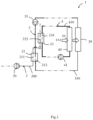
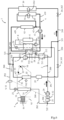
- FIG 1 and the figure 2 schematically illustrate a heat treatment system 1 for several functions of a motor vehicle, among which there is at least one ventilation, heating and/or air conditioning system for the passenger compartment, an electrical storage device and at least one element of an electric drive chain of the vehicle.
- the figure 1 partly represents the heat treatment system 1, while the figure 2 represents the entire heat treatment system 1 when it is produced according to a first embodiment.
- the heat treatment system 1 comprises a refrigerant loop 2, which is intended in particular for the heat treatment of a vehicle interior, a first heat transfer fluid circuit 3 and a second heat transfer fluid circuit 4.
- the heat transfer fluid is in particular a heat transfer liquid such as glycolated water.
- upstream refers to a direction of circulation S1 of the refrigerant fluid in the refrigerant loop 2, to a direction of circulation S2 of the heat transfer fluid in the first circuit 3 of heat transfer fluid, to a direction of circulation S3 of the heat transfer fluid in the second circuit 4 of heat transfer fluid or to a direction of circulation S4 of an external air flow FA1 to the passenger compartment of the vehicle.
- the refrigerant loop 2 successively comprises, according to the direction of circulation S1 of the refrigerant in the refrigerant loop 2, a compression device 20, a first heat exchanger 21 and a second heat exchanger 22, the first heat exchanger 21 and the second heat exchanger 22 being configured to implement a heat exchange between the refrigerant and the heat transfer fluid circulating in one and the other of the heat transfer fluid circuits of the heat treatment system 1.
- the first heat transfer fluid circuit 3 comprises the first heat exchanger 21 while the second heat transfer fluid circuit 4 comprises the second heat exchanger 22.
- the first heat transfer fluid circuit 3 also comprises at least one primary radiator 30, configured to implement a heat exchange between the heat transfer fluid and the flow of air outside FA1 to the passenger compartment of the vehicle, the primary radiator 30 being arranged downstream of the first heat exchanger 21 in the direction of circulation S2 of the heat transfer fluid in the first heat transfer fluid circuit 3.
- the first heat transfer fluid circuit 3 may comprise a member 31 for circulating the heat transfer fluid, for example a pump.
- the second heat transfer fluid circuit 4 further comprises at least one secondary radiator 40 configured to implement a heat exchange between the heat transfer fluid and the flow of air outside FA1 to the passenger compartment, the secondary radiator 40 being arranged upstream of the second heat exchanger 22 in the direction of circulation S3 of the heat transfer fluid in the second heat transfer fluid circuit 4.
- the second heat transfer fluid circuit 4 comprises at least one element 41 for circulating the refrigerant fluid in the second circuit, for example a pump.
- the primary radiator 30 and the secondary radiator 40 are exposed to the flow of outside air FA1 to the passenger compartment, the primary radiator 30 being arranged downstream of the secondary radiator 40 in the direction of circulation S4 of the flow of outside air FA1 through said radiators 30, 40. It is therefore understood that the secondary radiator 40 is crossed by the flow of outside air FA1 to the passenger compartment before the latter crosses the primary radiator 30.
- the primary radiator 30 and the secondary radiator 40 are arranged on the front of the vehicle, but they could also be installed on a roof of the vehicle, in a rear wing and generally in all areas of the vehicle that can be swept by the flow of outside air FA1.
- the refrigerant loop 2 consists of a closed loop which comprises at least one main branch 200 on which are arranged the compression device 20, intended to raise the pressure of the refrigerant, the first heat exchanger 21, the second heat exchanger 22, at least one expansion member, called primary expansion member 23, intended to reduce the pressure of the refrigerant, and at least one third heat exchanger 24, intended to thermally treat an interior air flow FA2, distinct from the exterior air flow FA1, and which is intended to be sent into the passenger compartment of the vehicle.
- the second heat exchanger 22 can be used as a subcooler or as a condenser as required.
- the second heat exchanger 22 is arranged between the first heat exchanger 21 and the primary expansion member 23, downstream of the first heat exchanger 21 in the direction of circulation S1 of the refrigerant fluid in the refrigerant loop 2. It should be noted that the different fluids circulating in the second heat exchanger 22 do not mix and that the heat exchange between these two fluids is done by conduction.
- the refrigerant loop 2 thus comprises a first portion 201, between the compression device 20 and the primary expansion member 23, in which the refrigerant is subjected to a high pressure, and a second portion 202, between the primary expansion member 23 and the compression device 20, in which the refrigerant is subjected to a low pressure, lower than the high pressure.
- the refrigerant loop 2 comprises an internal heat exchanger 5.
- This internal heat exchanger 5 makes it possible to recover calories from the refrigerant circulating in the first portion 201 to exchange them with the refrigerant circulating at another point in the refrigerant loop 2, in particular at the level of the second portion 202.
- the internal heat exchanger 5 contributes to reducing the power consumed by the compression device 20 and overall increasing the coefficient of performance of the refrigerant circuit.
- a first part 51 of the internal heat exchanger 5 may be arranged on a first tube 203, called high pressure and high temperature, of the main branch 200 of the refrigerant loop 2 while a second part 52 of the internal heat exchanger 5 is arranged at a second tube 204 of the main branch 200, called low pressure and low temperature.
- the refrigerant at low temperature being colder than the refrigerant at higher pressure, it is understood that the internal heat exchanger 5 allows an exchange of heat between its two parts 51, 52 and therefore between the two tubes 203, 204 of the refrigerant loop 2 on which these parts 51, 52 are arranged.
- the first part 51 of the internal heat exchanger 5 is arranged between the second heat exchanger 22 and the primary expansion member 23 and the second part 52 of this internal heat exchanger 5 is arranged between the third heat exchanger 24 and the compression device 20.
- the internal heat exchanger 5 allows the refrigerant fluid to be heated upstream of the compression device 20 so that this refrigerant fluid arrives in this compression device 20 in the gaseous state.
- the heat exchange implemented between the first part 51 of the internal heat exchanger 5 and the second part 52 of the internal heat exchanger 5 is schematically represented by the dotted line 500.
- the main branch 200 of the refrigerant circuit may also comprise an accumulation device 25 arranged between the third heat exchanger 24 and the second part 52 of the internal heat exchanger 5, upstream of the compression device 20.
- the accumulation device 25 makes it possible to accumulate a liquid phase of the refrigerant so as to guarantee that only a gaseous phase of the refrigerant flows towards the compression device 20. Also, the accumulation device 25 makes it possible to manage the quantity of refrigerant circulating in the refrigerant loop 2.
- the refrigerant loop 2 comprises a secondary branch 220 which diverges from the main branch 200 at a point of divergence 221, located between the second heat exchanger 22 and the primary expansion member 23, and which joins the main branch 200 at a point of convergence 222 located between the third heat exchanger 24 and the compression device 20.
- the secondary branch 220 successively comprises, according to the direction of circulation S1 of the refrigerant fluid in the refrigerant fluid loop 2, a secondary expansion member 29 and a fourth heat exchanger 27 thermally coupled to an electrical storage device 6 of the vehicle configured to electrically power at least one element of the electric powertrain of said vehicle.
- the electrical storage device 6 is included on a third heat transfer fluid circuit 8, which further comprises at least one circulator 81 intended to circulate the heat transfer fluid.
- the fourth heat exchanger 27 is thus arranged in parallel with the third heat exchanger 24, from the point of view of the refrigerant fluid. It is understood that the fourth heat exchanger 27 is configured to implement a heat exchange between the refrigerant fluid circulating in the secondary branch 220 and the heat transfer fluid circulating in the third heat transfer fluid circuit 8.
- the refrigerant loop 2 may comprise a bottle 26 and/or an additional expansion member, not shown, arranged between the first heat exchanger 21 and the second heat exchanger 22.
- the refrigerant loop 2 comprises at least one bottle 26 installed between the first heat exchanger 21 and the second heat exchanger 22.
- the first heat transfer fluid circuit 3 consists of a closed circuit which comprises a first line 310 on which are successively arranged, according to the direction of circulation S2 of the heat transfer fluid in the first heat transfer fluid circuit 3, at least the heat transfer fluid circulation member 31, the first heat exchanger 21 and the primary radiator 30.
- the first heat transfer fluid circuit 3 further comprises a branch line 320 which diverges from the first line 310 at a separation point 321 between the first heat exchanger 21 and the primary radiator 30 and which joins it at a junction point 322 located between the primary radiator 30 and the heat transfer fluid circulation member 31.
- the branch line 320 comprises an air heater 32 configured to implement a heat exchange between the heat transfer fluid and the interior air flow FA2 sent into the passenger compartment.
- the air heater 32 of the first heat transfer fluid circuit 3 and the third heat exchanger 24 are also included in an installation 9 for air conditioning, heating and/or ventilation of the passenger compartment of the vehicle.
- said installation 9 comprises at least one housing 91 for air conditioning, heating and/or ventilation, or housing 91, made of a heat-resistant synthetic material, in which the air heater 32 and the second heat exchanger 22 are arranged.
- the housing 91 comprises at least one inlet vent 92, intended to bring the interior air flow FA2 into the housing 91, and a plurality of outlet vents 93, intended to send the interior air flow FA2 thermally treated by the installation 9 to different zones of the passenger compartment of the vehicle.
- the installation 9 also comprises at least one fan 94 and a plurality of flaps and/or dampers 95 intended to direct the interior air flow FA2 within the housing 91, for example so that it passes through the air heater 32 or not, and into the various outlet nozzles 93.
- the first heat transfer fluid circuit 3 may comprise at least one electric heating device 33 for the heat transfer fluid arranged upstream of the air heater 32 in the direction of circulation S2 of the heat transfer fluid in the first heat transfer fluid circuit 3.
- the bypass line 320 ensures the bypass of the primary radiator 30.
- the first heat transfer fluid circuit 3 comprises at least one means for regulating the flow rate 34 of heat transfer fluid.
- the first heat transfer fluid circuit 3 may comprise two two-way valves, a first valve 341 being arranged on the bypass line 320, between the first heat exchanger 21 and the electric heating device 33 of the heat transfer fluid, and a second valve 342 being arranged on the first line 310, between the first heat exchanger 21 and the primary radiator 30.
- the first heat transfer fluid circuit 3 may comprise a three-way valve arranged at the separation point 321 or the junction point 322.
- the second heat transfer fluid circuit 4 consists of a closed circuit which comprises a first pipe 410 on which are successively arranged, according to the direction of circulation S3 of the heat transfer fluid in the second heat transfer fluid circuit 4, at least the heat transfer fluid circulation element 41, the second heat exchanger 22 and the secondary radiator 40.
- the second heat transfer fluid circuit 4 further comprises a second pipe 420 branching off from the first pipe 410, the second pipe 420 diverging and converging from the first pipe 410 on either side of the secondary radiator 40 respectively.
- the second heat transfer fluid circuit 4 further comprises a third pipe 430 which allows the heat transfer fluid to bypass either the secondary radiator 40 or a heat exchanger 43 thermally coupled to at least one element of the electric powertrain of the motor vehicle other than the electrical storage device 6.
- the third pipe 430 is devoid of a heat exchanger and thus behaves as a bypass line.
- the circulation of the heat transfer fluid along the second pipe 420 and/or the first pipe 410 and/or the third pipe 430 is, for example, controlled by a heat transfer fluid flow rate regulating element 42 such as a three-way valve or, alternatively, by a plurality of heat transfer fluid flow rate regulating elements 42, not shown.
- the second pipe 420 comprises the heat exchanger 43 thermally coupled to at least one element of the electric powertrain of the motor vehicle, for example an electric motor and/or a control module of this electric motor, and is arranged in order, for example, to carry out a heat exchange between the heat transfer fluid circulating in the second pipe 420 and the air flow FA1 outside the passenger compartment of the vehicle.
- the external air flow FA1 can ensure the cooling of the heat transfer fluid which can then capture via the heat exchanger 43 calories emitted by the element of the traction chain thermally.
- the first heat transfer fluid circuit 3 and the second heat transfer fluid circuit 4 of the heat treatment system 1 are distinct, the first heat transfer fluid circuit 3 and the second heat transfer fluid circuit 4 being two closed circuits independent of each other.
- FIGS. 3 to 5 represent different examples of operation of the heat treatment system 1 according to the first embodiment as shown in figure 2 .
- the solid lines represent pipes, lines or branches of the heat treatment system 1 in which the refrigerant fluid or the heat transfer fluid circulates
- the dotted lines represent pipes, lines or branches of the heat treatment system 1 in which neither the refrigerant nor the heat transfer fluid circulates.
- the indoor air flow FA2, the outdoor air flow FA1 and its circulation direction S4, a circulation direction S2 of the heat transfer fluid in the first heat transfer fluid circuit 3, a circulation direction S3 of the heat transfer fluid in the second heat transfer fluid circuit 4 and a circulation direction S1 of the refrigerant in the refrigerant loop 2 are also schematically represented on the various Figures 1 to 13
- the flow regulation elements or means 34, 42 of the heat transfer fluid or the refrigerant fluid are shown as solid when they block the circulation of the fluid concerned, and hollowed out when they allow said circulation.
- FIG. 3 thus illustrates a first example of operation of the heat treatment system 1 in which the refrigerant circuit 3 is configured to operate in passenger compartment cooling mode, i.e. air conditioning mode.
- the refrigerant circulates in the main branch 200, while the secondary branch 220 is not traversed by the refrigerant.
- the circulation of the refrigerant can be hindered by the closing of the secondary expansion member 29.
- the refrigerant fluid leaves the compression device 20 under high pressure, at high temperature and in the gaseous state towards the first heat exchanger 21 which functions as a condenser.
- the refrigerant fluid enters a first pass 211 of the first heat exchanger 21 in the gaseous state and at a temperature higher than the temperature of the heat transfer fluid circulating in a second pass 212 of the first heat exchanger 21 and transfers its calories to the heat transfer fluid.
- the refrigerant fluid thus cooled leaves the first heat exchanger 21 at least predominantly in the liquid state.
- the refrigerant is then brought to the level of the bottle 26, the liquid phase and the gas phase are separated and only the liquid phase is sent to the second heat exchanger 22.
- the refrigerant fluid then circulates in a first pass 223 of the second heat exchanger 22, this refrigerant fluid having a temperature higher than that of the heat transfer fluid circulating in a second pass 224 of the second heat exchanger 22, the fluid refrigerant gives off calories to the heat transfer fluid.
- the second heat exchanger 22 is configured to ensure the subcooling of the refrigerant, that is to say that the temperature difference between the refrigerant in the liquid state and the heat transfer fluid allows cooling of the refrigerant to a temperature lower than its condensation temperature.
- the refrigerant fluid leaving the second heat exchanger 22, in the liquid state, is sent to the first part 51 of the internal heat exchanger 5 where it is involved in a heat exchange as previously described, then the refrigerant fluid is brought to the primary expansion member 23 in which it undergoes a reduction in its pressure.
- the refrigerant joins the third heat exchanger 24, used as an evaporator, in which it is evaporated by capturing calories from the interior air flow FA2.
- the interior air flow FA2 is cooled and sent to the passenger compartment of the vehicle while the refrigerant leaves the third heat exchanger 24.
- the refrigerant then joins the accumulation device 25 in which the liquid phase and the gas phase are separated and the gas phase is sent to the second part 52 of the internal heat exchanger 5 then, again, to the compression device 20.
- the heat transfer fluid does not circulate in the bypass line 320 and the circulation of the heat transfer fluid takes place essentially at the level of the first line 310, such circulation being ensured by the selective opening and closing of the different means for regulating the flow rate 34 of the heat transfer fluid included in the first heat transfer fluid circuit 3, here the closing of the first two-way valve 341 and the opening of the second two-way valve 342.
- the heat transfer fluid is circulated in the first heat transfer fluid circuit 3 by the circulation member 31.
- the heat transfer fluid is brought to the first heat exchanger 21 and circulates in the second pass 212 of the first heat exchanger 21.
- the heat transfer fluid colder than the refrigerant fluid circulating in the first pass 211 of the first heat exchanger 21, is heated by the heat exchange carried out with the refrigerant fluid.
- the heat transfer fluid then circulates along the first line 310, passes through the separation point 321 and is then sent to the primary radiator 30.
- the heat transfer fluid entering the primary radiator 30 being at a temperature higher than the temperature of the outside air flow FA1, the heat transfer fluid gives off calories to the flows outside air FA1 and the latter is heated.
- the heat transfer fluid leaving the primary radiator 30, cooled, is then returned to the circulation member 31.
- the heat transfer fluid flows through the first pipe 410 and the second pipe 420, the partial closure of the heat transfer fluid flow regulating element 42 preventing the circulation of the heat transfer fluid in the third pipe 430.
- the heat transfer fluid is circulated in the second heat transfer fluid circuit 4 by the circulation element 41.
- the heat transfer fluid is brought into the second heat exchanger 22. As previously explained, it circulates in the second pass 224 of the second heat exchanger 22.
- the heat transfer fluid being colder than the liquid refrigerant fluid circulating in the first pass 223 of the second heat exchanger 22, the heat transfer fluid captures the calories from the refrigerant fluid, thus ensuring the subcooling of the latter.
- the heat transfer fluid leaves the second heat exchanger 22 heated and is brought to the secondary radiator 40.
- the secondary radiator 40 is arranged upstream of the primary radiator 30 in the direction of circulation of the outside air flow FA1 through the primary radiator 30 and secondary radiator 40.
- the outside air flow FA1 colder than the heat transfer fluid entering the secondary radiator 40 and then the primary radiator 30 respectively, thus initially passes through the secondary radiator 40, captures the calories of the heat transfer fluid circulating in the secondary radiator 40, then the heated outside air flow FA1 passes through the primary radiator 30 at which it captures the calories of the heat transfer fluid circulating in the primary radiator 30.
- the cooled heat transfer fluid leaving the secondary radiator 40 is then returned to the circulation element 41 and then to the second heat exchanger 22.
- the cooled heat transfer fluid leaving the secondary radiator 40 can also circulate in the second pipe 420 and thus capture the calories present in the heat exchanger 43 thermally coupled to at least one element of the electric powertrain of the motor vehicle.
- the second heat transfer fluid circuit 4 is therefore configured so that the secondary radiator 40 discharges into the exterior air flow FA1 the calories captured at the level of the first heat exchanger 21 and at the level of the heat exchanger 43 thermally coupled to at least one element of the electric drive chain of the motor vehicle.
- the secondary radiator 40 involved in the first heat exchange with the outside air flow FA1, is arranged in series with the second heat exchanger 22 which is configured to provide subcooling of the refrigerant fluid after its condensation phase.
- the primary radiator 30, involved in the second heat exchange with the outside air flow FA1 which has been heated a first time by heat exchange by passing through the secondary radiator 40, is arranged in series with the first heat exchanger 21, which is configured to condense the refrigerant fluid and therefore requires a smaller temperature difference between the heat transfer fluid and the refrigerant fluid than the second heat exchanger 22 used as a subcooler.
- the heat treatment system 1 operates in passenger compartment cooling mode, i.e. it allows fresh air to be sent into the passenger compartment of the vehicle.
- FIG 4 illustrates a second example of operation of the heat treatment system 1 according to the first embodiment implementing a passenger compartment cooling mode and a cooling mode of the electrical storage device 6, which can, for example, be implemented during a rapid charging phase of said electrical storage device 6.
- This second mode of operation differs from the first mode of operation in that, in the refrigerant loop 2, the refrigerant leaving the second heat exchanger 22, subcooled, is separated into two refrigerant flows at the point of divergence 221.
- a first refrigerant flow continues to circulate on the main branch 200 and follows a path identical to that previously described with reference to the figure 3 .
- a second flow of refrigerant fluid is sent to the secondary branch 220.
- the secondary expansion member 29 is partially open and allows the circulation of the refrigerant fluid in said secondary branch 220, causing a expansion thereof.
- the second flow of refrigerant fluid is directed towards the secondary expansion member 29 in which it undergoes expansion before joining the fourth heat exchanger 27.
- the refrigerant fluid circulating in a first pass 271 of the fourth heat exchanger 27 captures calories from the heat transfer fluid circulating in a second pass 272 of the fourth heat exchanger 27.
- the refrigerant leaves the fourth heat exchanger 27 in predominantly gaseous form and reaches the convergence point 222 at which the first refrigerant flow and the second refrigerant flow are combined in order to be directed to the accumulation device 25.
- the heat transfer fluid which has been cooled in the fourth heat exchanger 27 circulates in the third heat transfer fluid circuit 8 so as to cool the electrical storage device 6.
- FIG. 5 schematically represents a third example of operation of the heat treatment system 1 according to which the refrigerant loop 2 operates in passenger compartment heating mode, that is to say it operates the heating of the interior air flow FA2 before it is sent into the passenger compartment of the vehicle, and according to a heat recovery mode on the electrical storage device 6.
- the third heat exchanger 24 is inactive, in the sense that it is not crossed by the refrigerant.
- the refrigerant fluid leaves the compression device 20 in a gaseous state, at high pressure and at high temperature, and is supplied to the first heat exchanger 21.
- the first heat exchanger 21 is used as a condenser and the refrigerant fluid circulating in the first pass 211 of the first heat exchanger 21 is cooled by heat exchange with the heat transfer fluid circulating in the second pass 212 of the first heat exchanger 21.
- the cooled refrigerant fluid is sent to the bottle 26 then the liquid portion of the refrigerant fluid is sent to the second heat exchanger 22 for its subcooling by heat exchange with the heat transfer fluid circulating in the second pass 224 of the second heat exchanger 22.
- the refrigerant fluid leaving the second heat exchanger 22, subcooled, is then brought to the divergence point 221.
- the primary expansion member 23, included in the main branch 200 is closed, while the secondary expansion member 29, included in the secondary branch 220, is open.
- the circulation of the refrigerant fluid in the remainder of the main branch 200 is hindered and the refrigerant fluid is sent into the secondary branch 220 so as to bypass the third heat exchanger 24.
- the refrigerant fluid is sent to the secondary expansion member 29, in which it is expanded, then the low pressure and low temperature fluid is brought to the fourth heat exchanger 27, thermally coupled to the third heat transfer fluid circuit 8 and therefore to the electrical storage device 6.
- the third heat exchanger 24 operates as an evaporator, a temperature of this refrigerant fluid being lower than a temperature of the heat transfer fluid which circulates in the second pass 272 of the fourth heat exchanger 27, the refrigerant fluid captures the calories of the heat transfer fluid circulating in the third heat transfer fluid circuit 8, said heat transfer fluid then ensuring the cooling of the electrical storage device 6 of the vehicle.
- the calories transferred by the electrical storage device 6 to the heat transfer fluid of the third heat transfer fluid circuit 8 are recovered and make it possible to heat the refrigerant fluid of the refrigerant fluid loop 2 upstream of the compression device 20.
- the refrigerant fluid thus leaves the fourth heat exchanger 27 in an at least partially gaseous state and then joins the convergence point 222 then the accumulation device 25 on the main branch 200.
- the heat transfer fluid is circulated by the circulation member 31, then is sent to the first heat exchanger 21 in which it captures the calories from the refrigerant fluid circulating in the first pass 211 of the first heat exchanger 21, the heat transfer fluid is then brought to the separation point 321 of the first heat transfer fluid circuit 3.
- the flow rate regulation means 34 of the heat transfer fluid are configured to hinder the circulation of the heat transfer fluid in the remainder of the first line 310 and to send the heat transfer fluid to the bypass line 320.
- the first valve 341 two-way valve is open while the second two-way valve 342 is closed and the heat transfer fluid bypasses the primary radiator 30 which is then inactive.
- the heated heat transfer fluid circulates in the bypass line 320 to the electric heating device 33 which will ensure the heating of said heat transfer fluid.
- the heated heat transfer fluid is then sent to the air heater 32 in which it implements a heat exchange with the interior air flow FA2.
- the heat transfer fluid hotter than the interior air flow FA2, gives up calories to the interior air flow FA2 which is thus heated then sent to the passenger compartment via at least one of the outlet nozzles of the housing 91.
- the cooled heat transfer fluid then leaves the air heater 32 and is returned to the first line 310 of the first heat transfer fluid circuit 3, towards the circulation member 31.
- the path of the heat transfer fluid is substantially identical to that previously described with reference to the figure 4 , that is to say that the heat transfer fluid is circulated by the circulation element 41 then passes through the second heat exchanger 22, and possibly the heat exchanger 43 thermally coupled to at least one element of the electric drive chain of the motor vehicle.
- FIG. 6 represents a second embodiment of the heat treatment system 1 in which the first heat transfer fluid circuit 3 and second heat transfer fluid circuit 4 are identical to what has previously been explained with reference to Figures 1 to 5 , the first heat transfer fluid circuit 3 and the second heat transfer fluid circuit 4 being distinct and independent of each other.
- the refrigerant loop 2 is substantially identical to what was previously explained with reference to the first embodiment, it nevertheless differs from the latter in that it comprises an additional expansion member 28 in place of, or in addition to, the bottle 26 arranged between the first heat exchanger 21 and the second heat exchanger 22, on the main branch 200 of the refrigerant loop 2.
- the refrigerant fluid loop 2 successively comprises, according to the direction of circulation S1 of the refrigerant fluid in the refrigerant fluid loop 2, the compression device 20, the first heat exchanger 21, the additional expansion member 28 and the second heat exchanger 22.
- the refrigerant loop 2 can successively comprise, according to the direction of circulation S1 of the refrigerant in the refrigerant loop 2, the compression device 20, the first heat exchanger 21, the bottle 26, the additional expansion member 28 and the second heat exchanger 22, so as to ensure that only a liquid portion of the refrigerant leaving the first heat exchanger 21 is sent to the additional expansion member 28.
- the heat treatment system 1 When the heat treatment system 1 is produced according to this second embodiment, it can be used to implement a mode of cooling the passenger compartment or a mode of cooling the passenger compartment and cooling the electrical storage device 6, not shown, as they have been previously explained for the first embodiment with reference to figures 4 And 5 respectively.
- the descriptions made with reference to these figures are transposable to the heat treatment system 1 produced according to the present embodiment with the difference that instead of, or in addition to, the bottle 26, the refrigerant loop 2 comprises the additional expansion member 28.
- the additional expansion member 28 is then open and allows the refrigerant fluid to pass towards the second heat exchanger 22 without ensuring its expansion so that the path and the changes of state of the refrigerant fluid in the refrigerant loop 2 are strictly identical to those previously explained.
- the heat treatment system 1 When the heat treatment system 1 according to the present embodiment implements the heating and heat recovery mode, it can also implement the cooling of at least one of the elements of the chain of the electric traction chain. Such an operating mode is shown in figure 7 .
- the refrigerant leaves the compression device 20 under high pressure, at high temperature and in the gaseous state towards the first heat exchanger 21 which functions as a condenser.
- the refrigerant gives up calories to the heat transfer fluid circulating in the second pass 212 of the first heat exchanger 21 and leaves the first heat exchanger 21 in the essentially liquid state, or even entirely liquid.
- the cooled refrigerant is brought to the additional expansion member 28 at the level of which it undergoes a first expansion.
- the outgoing refrigerant, at low pressure and low temperature, is then sent to the second heat exchanger 22.
- the second heat exchanger 22 operates as an evaporator.
- the refrigerant fluid, colder than the heat transfer fluid circulating in the second pass 224 of the second heat exchanger 22, captures the calories from the latter, and leaves the second heat exchanger 22 heated and in an at least partially gaseous or two-phase state.
- the second heat transfer fluid circuit 4 makes it possible to cool at least one of the elements of the drive chain arranged on the second pipe 420, by means of the heat exchanger 43 thermally coupled to at least one element of the electric drive chain of the motor vehicle.
- the refrigerant leaving the second heat exchanger 22 is then brought to the level of the divergence point 221.
- the primary expansion member 23 is closed so as to hinder the circulation of the refrigerant in the remainder of the main branch 200, while the secondary expansion member 29 is partially open so as to allow the circulation of the refrigerant in the secondary branch 220 and to ensure the expansion of said fluid.
- the refrigerant fluid is thus directed on the secondary branch 220 to the secondary expansion member 29 at which it undergoes a second expansion, at a lower level than the first expansion implemented by the additional expansion member 28.
- the refrigerant fluid leaves the secondary expansion member 29 at low pressure and in the liquid state and is brought to the fourth heat exchanger 27 in which, as previously explained, it captures the calories from the heat transfer fluid circulating in the second pass 272 of the fourth heat exchanger 27 so as to allow the cooling of the electrical storage device 6.
- the calories released by the electrical storage device 6 make it possible to heat the refrigerant fluid of the refrigerant loop 2 upstream of the compression device 20.
- the refrigerant fluid thus leaves the fourth heat exchanger 27 in an at least partially gaseous state and then joins the convergence point 222, then the accumulation device 25 on the main branch 200.
- the secondary expansion member 29 can be completely open so as to allow the circulation of the refrigerant fluid along the secondary branch 220 without expanding it.
- FIGs 8 to 13 illustrate a third embodiment and a fourth embodiment of the heat treatment system 1 in which the first heat transfer fluid circuit 3 and the second heat transfer fluid circuit 4 are interconnected.
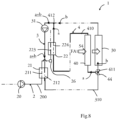
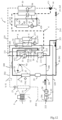
- figure 8 partly illustrates the heat treatment system 1 according to the third embodiment, while the figure 9 represents the whole of this same heat treatment system 1.
- the portion of heat treatment system 1 shown in figure 8 is substantially identical to that previously described with reference to the figure 1 , it is nevertheless distinguished from the latter by the arrangement of the second circuit 4 of heat transfer fluid in the heat treatment system 1.
- FIG 8 shows that the circulation member 31 draws in a flow of heat transfer fluid illustrated by a+b and pushes this flow a+b into the first line 310 of the first heat transfer fluid circuit 3.
- the heat transfer fluid splits into a first flow a which enters the second heat transfer fluid circuit 4 and a second flow b which continues its path in the first heat transfer fluid circuit 3.
- the first flow a and the second flow b are joined at the connection point 412, before returning to the circulation member 31.
- the second heat transfer fluid circuit 4 extends between a bifurcation point 411 and a connection point 412.
- the bifurcation point 411 is arranged on the first heat transfer fluid circuit 3 upstream of the primary radiator 30 in the direction of circulation S2 of the heat transfer fluid in the first heat transfer fluid circuit 3. More specifically, the bifurcation point 411 is arranged between the first heat exchanger 21 and the primary radiator 30.
- the connection point 412 is arranged on the first heat transfer fluid circuit 3, upstream of the first heat exchanger 21 in the direction of circulation S2 of the heat transfer fluid in the first heat transfer fluid circuit 3. More specifically, the connection point 412 is arranged between the primary radiator 30 and the first heat exchanger 21.
- the heat treatment system 1 comprises at least one heat transfer fluid flow rate regulating member 44 arranged at the bifurcation point 411, as illustrated, or at the connection point 412.
- the refrigerant fluid flow rate regulating member 44 may be a three-way valve.
- the heat treatment system 1 may comprise a plurality of flow regulating members 44 of the heat transfer fluid, for example two-way valves, respectively arranged on the first line 310 of the first heat transfer fluid circuit 3 and on the first pipe 410 of the second heat transfer fluid circuit 4.
- the heat treatment system 1 comprises the heat transfer fluid circulation member 31, arranged on the first line 310 of the first heat transfer fluid circuit 3, but may be devoid of the circulation element 41 of the second heat transfer fluid circuit 4 as previously described.
- FIG 9 represents the heat treatment system 1 as a whole, when it is produced according to the third embodiment as described with reference to the figure 8 .
- the refrigerant fluid loop 2 is identical to that previously described with reference to the Figures 1 to 7 for the first and second embodiments of the present invention.
- the heat transfer fluid loop 6 may comprise the bottle 26 and/or the additional expansion member as previously described.
- the refrigerant fluid loop 2 will comprise only the bottle 26.
- the first line 310 is identical to that previously described for the first and second embodiments.
- the bypass line 320 comprises the air heater 32, configured to implement a heat exchange between the heat transfer fluid and the interior air flow FA2 sent into the passenger compartment of the vehicle, and the bypass line 320 extends between the separation point 321 and the junction point 322.
- the separation point 321 is arranged downstream of the first heat exchanger 21 in the direction of circulation S2 of the heat transfer fluid in the first heat transfer fluid circuit 3, more specifically between the first heat exchanger 21 and the primary radiator 30.
- the third embodiment differs from the first and second embodiments in that the junction point 322 of the bypass line 320 is arranged on the second heat transfer fluid circuit 4, upstream of the second heat exchanger 22 in the direction of circulation S3 of the heat transfer fluid in the second heat transfer fluid circuit 4, the junction point 322 being arranged between the secondary radiator 40 and the second heat exchanger 22.
- the second pipe 420 comprises, as previously explained, the heat exchanger 43 thermally coupled to at least one of the elements of the electric powertrain of the motor vehicle and the second pipe 420 diverges and converges from the first pipe 410 on either side of the secondary radiator 40 respectively.
- the third pipe 430 is placed in parallel with this heat exchanger 43 thermally coupled to at least one of the elements of the electric powertrain and in parallel with the secondary radiator 40, so that the heat transfer fluid can bypass these components depending on the position taken by the flow control member 42.
- FIG. 10 represents the heat treatment system 1 according to the third embodiment when it operates in a passenger compartment cooling mode.
- the architecture of the refrigerant loop 2 and the path of the refrigerant in said loop 2 are identical to what was previously described for the heat treatment system 1 produced according to the first embodiment.
- the description of the refrigerant loop 2 made for the passenger compartment cooling mode with reference to the figure 3 is transposable to the present embodiment.
- the heat transfer fluid is circulated in the first heat transfer fluid circuit 3 by the circulation member 31, the heat transfer fluid is sent to the first heat exchanger 21 where it circulates in the second pass 212 of the first heat exchanger 21 and captures the calories of the refrigerant fluid, hotter, circulating in the first pass 211 of the first heat exchanger 21.
- the heat transfer fluid leaving the first heat exchanger 21, reheated, is then brought to the separation point 321.
- the means for regulating the flow rate 34 of the heat transfer fluid are configured to hinder the circulation of the heat transfer fluid towards the bypass line 320.
- the first two-way valve 341 is thus closed while the second two-way valve 342 is open.
- the heat transfer fluid thus circulates along the first line 310 of the first circuit 3 of heat transfer fluid up to the bifurcation point 411.
- the flow rate regulating member 44 of the heat transfer fluid is open so as to allow the simultaneous circulation of a first flow of heat transfer fluid in the first line 310 of the first heat transfer fluid circuit 3 and a second heat transfer fluid flow in the first pipe 410 of the second heat transfer fluid circuit 4.
- the heat transfer fluid thus circulates in parallel in the primary radiator 30 and in the secondary radiator 40.
- the first flow of heat transfer fluid which continues to circulate along the first line 310 of the first circuit 3 of heat transfer fluid, is sent to the primary radiator 30.
- the heat transfer fluid hotter than the flow of outside air FA1 in the passenger compartment, gives up calories to the flow of outside air FA1 and is cooled.
- This first flow of heat transfer fluid then circulates along the first line 310 of the first circuit 3 of heat transfer fluid to the circulation member 31.
- the second heat transfer fluid flow sent into the first pipe 410 of the second heat transfer fluid circuit 4, circulates to the secondary radiator 40.
- the heat transfer fluid hotter than the outside air flow FA1 gives up calories to this outside air flow FA1.
- the cooled heat transfer fluid circulates in the first pipe 410 of the second heat transfer fluid circuit 4 to the second heat exchanger 22. Similar to what was previously explained for the first and second embodiments, the heat transfer fluid circulating in the second pass 224 of the second heat exchanger 22 captures the calories from the refrigerant fluid circulating in the first pass 223 of the second heat exchanger 22 and ensures the subcooling of the latter.
- the heat transfer fluid leaving the second heat exchanger 22 is then brought to the connection point 412 at which it joins the first line 310 of the first heat transfer fluid circuit 3, is combined with the first flow of heat transfer fluid, then is returned to the heat transfer fluid circulation member 31.
- the heat transfer fluid circulating in the secondary radiator is thus crossed by the flow of outside air subjected to the ambient temperature, that is to say the lowest available in the air outside the passenger compartment.
- the subcooling which takes place in the second heat exchanger 22 is therefore ensured with the coldest air available.
- the air flow FA1 heated by the secondary radiator 40 passes through the primary radiator 30 at a temperature which nevertheless allows the condensation of the refrigerant fluid at the heart of the first heat exchanger 21.
- the heat transfer fluid flow regulating element 42 is placed in a position where the second pipe 420 is isolated from the second heat transfer fluid circuit 4. Circulation can nevertheless take place in a loop formed by the third pipe 430 and by the second pipe 420, by operating the heat transfer fluid circulation element 41.
- the heat transfer fluid flow regulating element 42 is placed in a position where the calories captured at the heat exchanger 43 thermally coupled to at least one of the elements of the electric drive chain are discharged into the outside air flow FA1 via the secondary radiator 40.
- the heat treatment system 1 does not, in the present operating mode, support the cooling of the electrical storage device 6.
- FIG 11 represents an example of a second mode of operation of the heat treatment system 1 according to the third embodiment when the latter implements a passenger compartment cooling mode and a cooling mode of the electrical storage device 6, for example implemented during a rapid charging phase of said electrical storage device 6.
- the path of the heat transfer fluid in the first heat transfer fluid circuit 3 and in the second heat transfer fluid circuit 4 is identical to that previously explained with reference to the figure 10 for the cooling mode of the passenger compartment of the heat treatment system 1 according to the third embodiment, the description given of the path of the heat transfer fluid in these two circuits 3, 4 is thus transposable to the present operating mode.
- This second operating mode is distinguished from the first operating mode of the heat treatment system 1 according to the third embodiment in that the refrigerant fluid leaving the second heat exchanger 22, subcooled, is separated into two flows of refrigerant fluid at the level of the point of divergence 221.
- the first flow of refrigerant fluid continues to circulate on the main branch 200 while the second flow of refrigerant fluid is sent on the secondary branch 220, towards the secondary expansion member 29.
- the second flow of liquid refrigerant fluid is expanded in the secondary expansion member 29 and is then brought into the fourth heat exchanger 27 in which it captures calories from the heat transfer fluid circulating in the second pass 272 of the fourth heat exchanger 27.
- the refrigerant fluid leaves the fourth exchanger in an at least partially gaseous state and reaches the convergence point 222 in order to be directed towards the accumulation device 25.
- the heat transfer fluid which has been cooled in the fourth heat exchanger 27 circulates in the third heat transfer fluid circuit 8 so as to cool the electrical storage device 6.
- FIG 12 illustrates an example of a third operating mode in which the heat treatment system 1 according to the third embodiment simultaneously implements a heating mode of the interior air flow FA2 sent to the passenger compartment and a heat recovery mode.
- the present operating mode is substantially identical to the heating and calorie recovery mode previously described for the first embodiment with reference to the figure 5 , the description of the refrigerant loop 2 and the path of the refrigerant in said loop 2 is therefore transposable to the present embodiment.
- the heat transfer fluid is successively circulated by the circulation member 31, sent into the first heat exchanger 21, in which it captures the calories from the refrigerant fluid circulating in the first pass 211 of the first heat exchanger 21, then is brought to the separation point 321 of the first heat transfer fluid circuit 3.
- the first two-way valve 341 When the heat treatment system 1 operates in heating and heat recovery mode, the first two-way valve 341 is open while the second two-way valve 342 is closed, these means for regulating the flow rate 34 of the heat transfer fluid hinder the circulation of the heat transfer fluid in the remainder of the first line 310 and send the heat transfer fluid to the bypass line 320 of the first refrigerant circuit so as to bypass the primary radiator 30 which is then inactive.
- the heated heat transfer fluid circulates in the bypass line 320 to the electric heating device 33 which will provide additional heating of said heat transfer fluid, then the heat transfer fluid is brought into the air heater 32.
- the heat transfer fluid hotter than the interior air flow FA2, gives off calories to the interior air flow FA2 which is thus heated then sent to the passenger compartment via at least one of the outlet nozzles of the housing 91.
- the cooled heat transfer fluid then leaves the air heater 32 and circulates along the bypass line 320 to the junction point 322.
- the heat transfer fluid is then brought to the first pipe 410 of the second heat transfer fluid circuit 4, between the secondary radiator 40 and the second heat exchanger 22.
- the heat transfer fluid circulates in the second pass 224 of the second heat exchanger 22 within which it implements a heat exchange with the refrigerant fluid circulating in the first pass 223 of the second heat exchanger 22.
- the heat transfer fluid captures the calories of said refrigerant fluid so as to allow the subcooling of the latter and then the heat transfer fluid circulates along the first pipe 410 to the connection point 412 and is returned on the first line 310 of the first heat transfer fluid circuit 3 to the circulation member 31.
- the heat transfer fluid flow regulating element 42 is placed in a position where the second pipe 420 is isolated from the second heat transfer fluid circuit 4. Circulation can nevertheless take place in a loop formed by the third pipe 430 and by the second pipe 420, by operating the heat transfer fluid circulation element 41.
- the heat transfer fluid flow regulating element 42 is placed in a position where the calories captured at the heat exchanger 43 thermally coupled to at least one of the elements of the electric drive chain are discharged into the outside air flow FA1 via the secondary radiator 40.
- FIG 13 represents the processing system when it is implemented according to the fourth embodiment of the present invention.
- This fourth embodiment is substantially identical to the third embodiment, shown in Figures 8 to 12 .
- the description of the heat treatment system 1 according to the third embodiment, made with reference to the figure 9 is transposable to the present embodiment.
- This fourth embodiment is distinguished from the third embodiment by the positioning of the bifurcation point 411 of the first pipe 410 of the second circuit 4 of heat transfer fluid.
- the bifurcation point 411 is arranged downstream of the primary radiator 30 in the direction of circulation S2 of the heat transfer fluid in the first heat transfer fluid circuit 3, the bifurcation point 411 being arranged between the primary radiator 30 and the first heat exchanger 21.
- the control of the circulation of the heat transfer fluid in the first line 310 of the first heat transfer fluid circuit 3 and/or in the first pipe 410 of the second heat transfer fluid circuit 4 is implemented by at least one heat transfer fluid flow rate regulating member 44, such as a three-way valve, which may, for example, be arranged at the bifurcation point 411 or the connection point 412.
- the heat treatment system 1 may comprise a plurality of heat transfer fluid flow rate regulating members 44 arranged on the first pipe 410 and on the first line 310.
- FIG 14 illustrates an example of operation of the heat treatment system 1 according to the fourth embodiment when the latter implements a passenger compartment cooling mode.
- the architecture of the refrigerant fluid loop 2 and the path of the refrigerant fluid in said circuit are identical to what was previously described for the heat treatment system 1 produced according to the third embodiment operating according to the cooling mode, thus, the description made with reference to the figure 10 is transposable to the present embodiment.
- the path of the heat transfer fluid is also identical between the circulation member 31 and the separation point 321.
- the means for regulating the flow rate 34 of the heat transfer fluid are configured to hinder the circulation of the heat transfer fluid to the bypass line 320.
- the first two-way valve 341 is thus closed while the second two-way valve 342 is open.
- the heat transfer fluid circulates along the first line 310 of the first heat transfer fluid circuit 3 to the primary radiator 30 at which the heat transfer fluid, hotter than the outside air flow FA1 to the passenger compartment, gives off calories to the outside air flow FA1.
- the outgoing heat transfer fluid, cooled, then circulates along the first line 310 of the first heat transfer fluid circuit 3 to the bifurcation point 411.
- the flow regulating member 44 of heat transfer fluid is open so as to simultaneously allow the circulation of the fluid heat transfer fluid along the remainder of the first line 310 of the first heat transfer fluid circuit 3 and along the first pipe 410 of the second heat transfer fluid circuit 4.
- the first heat transfer fluid flow continues to circulate along the first line 310 of the first heat transfer fluid circuit 3 towards the circulation member 31 while the second heat transfer fluid flow is sent to the first pipe 410 of the second heat transfer fluid circuit 4, towards the secondary radiator 40.
- the second flow of heat transfer fluid is advantageously involved in two successive heat exchanges with the flow of external air FA1, respectively in the primary radiator 30 then in the secondary radiator 40.
- the heat transfer fluid flow rate regulating member 44 can be configured so that the second heat transfer fluid flow circulates at a lower flow rate in the first pipe 410, and therefore in the secondary radiator 40.
- the second cooled heat transfer fluid flow is then, as previously explained, sent along the first pipe 410 to the second heat exchanger 22, in which it allows the subcooling of the refrigerant circulating in the first pass 223 of the second heat exchanger 22.
- the second heat transfer fluid flow then joins, as previously explained, the first heat transfer fluid flow at the connection point 412 arranged in the first line 310 of the first heat transfer fluid circuit 3 and is then returned to the circulation member 31.
- this fourth embodiment makes it possible to maximize the subcooling of the refrigerant fluid while minimizing the operating costs of the heat treatment system 1, and in particular the utility requirements of the second heat exchanger 22.
- the heat treatment system 1 according to the fourth embodiment can also implement the mode of cooling the passenger compartment and cooling the electrical storage device 6, not shown, as previously explained for the third embodiment with reference to the figure 10 .
- the refrigerant loop 2 operates in a similar manner to what has been explained for the third operating mode. Also, the description of the refrigerant loop 2 and of the path of the refrigerant in said loop 2 made with reference to the figure 10 can be transposed to the present fourth embodiment. Similarly, the circulation of the heat transfer fluid in the first heat transfer fluid circuit 3 and in the second heat transfer fluid circuit 4 is identical to what has been described in the passenger compartment cooling mode of the fourth embodiment, with reference to the figure 14 of this document.
- the heat treatment system 1 according to the fourth embodiment can also implement the heating and calorie recovery mode, not shown, as set out above for the third embodiment with reference to the figure 12 .
- the refrigerant fluid loop 2, the first heat transfer fluid circuit 3 and the second heat transfer fluid circuit 4 operating in a similar manner to that set out for the third operating mode, the description made with reference to the figure 12 and the third embodiment can be fully transposed to the present fourth embodiment.
- the present invention thus proposes a heat treatment system comprising a refrigerant loop, a first heat transfer fluid circuit and a second heat transfer fluid circuit, the first heat transfer fluid loop comprising a primary radiator and the second heat transfer fluid circuit comprising a secondary radiator, the primary radiator being arranged downstream of the secondary radiator in a direction of circulation of the outside air flow through said radiators.
- the first heat transfer fluid circuit comprises in particular at least one first heat exchanger configured to operate as a condenser of the refrigerant circulating in the refrigerant loop while the second heat transfer fluid circuit comprises at least one second heat exchanger configured to implement the subcooling of the refrigerant circulating in this same refrigerant loop.
- the present invention cannot, however, be limited to the means and configurations described and illustrated here and it also extends to any technically operative combination of such means.
- the architecture of the refrigerant fluid loop and the architecture of the first heat transfer fluid circuit and/or the second heat transfer fluid circuit may be modified without harming the invention to the extent that they make it possible to fulfill the functionalities of the heat treatment system 1 described and illustrated in this document.
Landscapes
- Engineering & Computer Science (AREA)
- Mechanical Engineering (AREA)
- Thermal Sciences (AREA)
- Physics & Mathematics (AREA)
- Life Sciences & Earth Sciences (AREA)
- Sustainable Development (AREA)
- Sustainable Energy (AREA)
- Combustion & Propulsion (AREA)
- Chemical & Material Sciences (AREA)
- Power Engineering (AREA)
- Transportation (AREA)
- Air-Conditioning For Vehicles (AREA)
- Cooling, Air Intake And Gas Exhaust, And Fuel Tank Arrangements In Propulsion Units (AREA)
Claims (10)
- Wärmebehandlungssystem (1) für ein Fahrzeug, das mindestens eine Kühlmittelschleife (2), einen ersten Wärmeübertragungsmediumkreislauf (3) und einen zweiten Wärmeübertragungsmediumkreislauf (4) umfasst,- wobei die Kühlmittelschleife (2) mindestens einen ersten Wärmetauscher (21) und einen zweiten Wärmetauscher (22) umfasst, die beide dazu ausgestaltet sind, einen Wärmetausch zwischen dem Kühlmittel und dem Wärmeübertragungsmedium, die in dem ersten Wärmeübertragungsmediumkreislauf (3) bzw. in dem zweiten Wärmeübertragungsmediumkreislauf (4) umlaufen, zu realisieren, wobei die Kühlmittelschleife (2) einen dritten Wärmetauscher (24) umfasst, der dazu ausgestaltet ist, einen Wärmeaustausch zwischen dem Kühlmittel und einem inneren Luftstrom (FA2), der in den Fahrgastraum des Fahrzeugs geleitet wird, zu realisieren,- wobei der erste Wärmeübertragungsmediumkreislauf (3) den ersten Wärmetauscher (21) und mindestens einen Primärkühler (30) umfasst, der dazu ausgestaltet ist, einen Wärmeaustausch zwischen einem Luftstrom (FA1) außerhalb des Fahrgastraums des Fahrzeugs und dem Wärmeübertragungsmedium zu realisieren,- wobei der zweite Wärmeübertragungsmediumkreislauf (4) den zweiten Wärmetauscher (22) und mindestens einen Sekundärkühler (40) umfasst, der dazu ausgestaltet ist, einen Wärmeaustausch zwischen dem Außenluftstrom (FA1) und dem Wärmeübertragungsmedium zu realisieren,wobei der Primärkühler (30) stromabwärts von dem Sekundärkühler (40) in einer Umlaufrichtung (S4) des Außenluftstroms (FA1) durch diese Kühler (30, 40) angeordnet ist,wobei bei dem Wärmebehandlungssystem (1) die Kühlmittelschleife (2) eine Schleife ohne Ausgang ist, dadurch gekennzeichnet, dass die Schleife ohne Ausgang mindestens einen Hauptzweig (200) umfasst, an dem nacheinander mindestens eine Verdichtungsvorrichtung (20), der erste Wärmetauscher (21), der zweite Wärmetauscher (22), mindestens ein Expansionselement, das primäres Expansionselement (23) genannt wird, und mindestens der dritte Wärmetauscher (24) angeordnet sind.
- Wärmebehandlungssystem (1) nach dem vorhergehenden Anspruch, wobei die Kühlmittelschleife (2) eine Flasche (26) und/oder ein zusätzliches Expansionselement (28) umfasst, das bzw. die zwischen dem ersten Wärmetauscher (21) und dem zweiten Wärmetauscher (22) angeordnet ist.
- Wärmebehandlungssystem (1) nach Anspruch 1 oder 2, wobei die Kühlmittelschleife (2) einen Sekundärzweig (220) umfasst, der sich zwischen einem ersten Divergenzpunkt (221), der zwischen dem zweiten Wärmetauscher (22) und dem primären Expansionselement (23) angeordnet ist, und einem ersten Konvergenzpunkt (222), der zwischen dem dritten Wärmetauscher (24) und der Verdichtungsvorrichtung (20) angeordnet ist, erstreckt, wobei der Sekundärzweig (220) mindestens ein sekundäres Expansionselement (223) und einen vierten Wärmetauscher (27) umfasst, der thermisch an eine elektrische Speichervorrichtung (6) des Fahrzeugs gekoppelt ist.
- Wärmebehandlungssystem (1) nach einem der vorhergehenden Ansprüche, wobei der zweite Wärmeübertragungsmediumkreislauf (4) mindestens eine erstes Rohr (410), das mindestens den Sekundärkühler (40) aufweist, ein Element (41) zum Zirkulieren des Wärmeübertragungsmediums in dem zweiten Kreislauf und den zweiten Wärmetauscher (22) umfasst, wobei der zweite Wärmeübertragungsmediumkreislauf (4) mindestens ein zweites Rohr (420) umfasst, das von dem ersten Kanal (410) abzweigt, wobei das zweite Rohr (420) einen Wärmetauscher (43) umfasst, der an mindestens ein Element des elektrischen Antriebsstrangs des Fahrzeugs thermisch gekoppelt ist.
- Wärmebehandlungssystem (1) nach einem der vorhergehenden Ansprüche, wobei der erste Wärmeübertragungsmediumkreislauf (3) mindestens eine erste Leitung (310) umfasst, auf der mindestens der Primärkühler (30), der erste Wärmetauscher (21) und ein Element (31) zum Zirkulieren des Wärmeübertragungsmediums in dem ersten Wärmeübertragungsmediumkreislauf (3) angeordnet sind.
- Wärmebehandlungssystem (1) nach Anspruch 5, wobei der erste Wärmeübertragungsmediumkreislauf (3) und der zweite Wärmeübertragungsmediumkreislauf (4) separat sind.
- Wärmebehandlungssystem (1) nach Anspruch 6, wobei der erste Wärmeübertragungsmediumkreislauf (3) mindestens eine Abzweigleitung (320) umfasst, die einen Thermoblock (32) umfasst, der dazu ausgestaltet ist, den Wärmeaustausch zwischen dem Wärmeübertragungsmedium und dem in den Fahrgastraum des Fahrzeugs geleiteten internen Luftstrom (FA2) zu realisieren, wobei sich die Abzweigleitung (320) zwischen einer Trennstelle (321) und einer Anschlussstelle (322) erstreckt, wobei die Trennstelle (321) in Umlaufrichtung (S2) des Wärmeübertragungsmediums in dem ersten Wärmeübertragungsmediumkreislauf (3) stromabwärts von dem ersten Wärmetauscher (21) liegt, und die Trennstelle (321) zwischen dem ersten Wärmetauscher (21) und dem Primärkühler (30) angeordnet ist, wobei die Anschlussstelle (322) in Umlaufrichtung (S2) des Wärmeübertragungsmediums in dem ersten Wärmeübertragungsmediumkreislauf (3) stromaufwärts von dem ersten Wärmetauscher (21) liegt, und die Anschlussstelle (322) zwischen dem Primärkühler (30) und dem ersten Wärmetauscher (21) angeordnet ist.
- Wärmebehandlungssystem (1) nach Anspruch 5, wobei der erste Wärmeübertragungsmediumkreislauf (3) und der zweite Wärmeübertragungsmediumkreislauf (4) verbunden sind.
- Wärmebehandlungssystem (1) nach dem vorhergehenden Anspruch, wobei der erste Wärmeübertragungsmediumkreislauf (3) mindestens eine Abzweigleitung (320) umfasst, die einen Thermoblock (32) aufweist, der dazu ausgestaltet ist, einen Wärmeaustausch zwischen dem Wärmeübertragungsmedium und dem in den Fahrgastraum des Fahrzeugs geleiteten internen Luftstrom (FA2) zu realisieren, wobei sich die Abzweigleitung (320) zwischen einer Trennstelle (321) und einer Anschlussstelle (322) erstreckt, wobei die Trennstelle (321)in Umlaufrichtung (S2) des Wärmeübertragungsmediums in dem ersten Wärmeübertragungsmediumkreislauf (3) stromabwärts von dem ersten Wärmetauscher (21) liegt, und die Trennstelle (321) zwischen dem ersten Wärmetauscher (21) und dem Primärkühler (30) angeordnet ist, wobei die Anschlussstelle (322) in Umlaufrichtung (S3) des Wärmeübertragungsmediums in dem zweiten Wärmeübertragungsmediumkreislauf (4) stromaufwärts von dem zweiten Wärmetauscher (22) liegt, wobei die Anschlussstelle (322) zwischen dem Sekundärkühler (40) und dem zweiten Wärmetauscher (22) angeordnet ist.
- Wärmebehandlungssystem (1) nach Anspruch 8 oder 9, wobei sich der zweite Wärmeübertragungsmediumkreislauf (4) zwischen einer Gabelungsstelle (411) und einer Verbindungsstelle (412) erstreckt, wobei die Verbindungsstelle (412) in Umlaufrichtung (S2) des Wärmeübertragungsmediums in dem ersten Wärmeübertragungsmediumkreislauf (3) stromaufwärts von dem ersten Wärmetauscher (21) auf dem ersten Wärmeübertragungsmediumkreislauf (3) angeordnet ist, wobei die Verbindungsstelle (412) zwischen dem Primärkühler (30) und dem ersten Wärmetauscher (21) angeordnet ist, und die Gabelungsstelle (411) auf dem ersten Wärmeübertragungsmediumkreislauf (3) entweder in Umlaufrichtung (S2) des Wärmeübertragungsmediums in dem ersten Wärmeübertragungsmediumkreislauf (3) stromaufwärts von dem Primärkühler (30) angeordnet ist, wobei die Gabelungsstelle (411) zwischen dem ersten Wärmetauscher (21) und dem Primärkühler (30) angeordnet ist, oder in Umlaufrichtung (S2) des Wärmeübertragungsmediums in dem ersten Wärmeübertragungsmediumkreislauf (3) stromabwärts von dem Primärkühler (30) angeordnet ist, wobei die Gabelungsstelle (411) zwischen dem Primärkühler (30) und dem ersten Wärmetauscher (21) angeordnet ist.
Applications Claiming Priority (2)
| Application Number | Priority Date | Filing Date | Title |
|---|---|---|---|
| FR1910672A FR3101281B1 (fr) | 2019-09-26 | 2019-09-26 | Systeme de traitement thermique destine a un vehicule automobile |
| PCT/FR2020/051645 WO2021058902A1 (fr) | 2019-09-26 | 2020-09-22 | Systeme de traitement thermique destine a un vehicule automobile |
Publications (2)
| Publication Number | Publication Date |
|---|---|
| EP4034397A1 EP4034397A1 (de) | 2022-08-03 |
| EP4034397B1 true EP4034397B1 (de) | 2025-02-26 |
Family
ID=68501845
Family Applications (1)
| Application Number | Title | Priority Date | Filing Date |
|---|---|---|---|
| EP20789653.1A Active EP4034397B1 (de) | 2019-09-26 | 2020-09-22 | Wärmebehandlungssystem für ein kraftfahrzeug |
Country Status (4)
| Country | Link |
|---|---|
| EP (1) | EP4034397B1 (de) |
| CN (1) | CN114514128B (de) |
| FR (1) | FR3101281B1 (de) |
| WO (1) | WO2021058902A1 (de) |
Families Citing this family (1)
| Publication number | Priority date | Publication date | Assignee | Title |
|---|---|---|---|---|
| US20210394587A1 (en) * | 2020-06-19 | 2021-12-23 | Carrier Corporation | Integrated cooling system and method for transportion refrigeration unit |
Family Cites Families (12)
| Publication number | Priority date | Publication date | Assignee | Title |
|---|---|---|---|---|
| FR2976653B1 (fr) * | 2011-06-16 | 2018-05-25 | Valeo Systemes Thermiques | Circuit de fluide refrigerant et procede de controle d'un tel circuit. |
| FR2982355A1 (fr) * | 2011-11-03 | 2013-05-10 | Valeo Systemes Thermiques | Boucle de climatisation pour une installation de chauffage, ventilation et/ou climatisation |
| FR2984471B1 (fr) * | 2011-12-15 | 2013-11-29 | Valeo Systemes Thermiques | Dispositif de conditionnement thermique d'une chaine de traction et d'un habitacle de vehicule |
| FR3013268B1 (fr) * | 2013-11-18 | 2017-02-17 | Valeo Systemes Thermiques | Systeme de conditionnement thermique pour vehicule automobile et installation de chauffage, ventilation et/ou climatisation correspondante |
| GB2529162B (en) * | 2014-08-11 | 2017-11-08 | Jaguar Land Rover Ltd | A vehicle arrangement |
| EP3012133B1 (de) * | 2014-10-21 | 2017-10-25 | Atieva, Inc. | Ev-mehrfachmodus-wärmeregelungssystem |
| US10279647B2 (en) * | 2016-03-23 | 2019-05-07 | Hanon Systems | Integrated thermal management system |
| FR3056289B1 (fr) * | 2016-09-16 | 2018-09-28 | Valeo Systemes Thermiques | Circuit de gestion thermique pour vehicule automobile |
| US11021037B2 (en) * | 2017-11-07 | 2021-06-01 | Hanon Systems | Thermal management system |
| KR102496797B1 (ko) * | 2017-12-11 | 2023-02-06 | 현대자동차 주식회사 | 차량용 히트 펌프 시스템 |
| DE102018104410A1 (de) * | 2018-02-27 | 2019-08-29 | Hanon Systems | Klimatisierungssystem eines Kraftfahrzeugs und Verfahren zum Betreiben des Klimatisierungssystems |
| CN108638787B (zh) * | 2018-05-09 | 2022-01-04 | 贾宏涛 | 一种用于电动汽车的水循环式热能综合利用热管理系统 |
-
2019
- 2019-09-26 FR FR1910672A patent/FR3101281B1/fr active Active
-
2020
- 2020-09-22 EP EP20789653.1A patent/EP4034397B1/de active Active
- 2020-09-22 WO PCT/FR2020/051645 patent/WO2021058902A1/fr not_active Ceased
- 2020-09-22 CN CN202080067815.5A patent/CN114514128B/zh active Active
Also Published As
| Publication number | Publication date |
|---|---|
| FR3101281A1 (fr) | 2021-04-02 |
| WO2021058902A1 (fr) | 2021-04-01 |
| CN114514128A (zh) | 2022-05-17 |
| CN114514128B (zh) | 2024-08-16 |
| EP4034397A1 (de) | 2022-08-03 |
| FR3101281B1 (fr) | 2022-06-24 |
Similar Documents
| Publication | Publication Date | Title |
|---|---|---|
| FR3074272B1 (fr) | Circuit de gestion thermique d'un vehicule hybride ou electrique | |
| EP2791596B1 (de) | Vorrichtung zur klimatisierung eines antriebsstrangs und eines fahrzeuginnenraums | |
| EP2263894B1 (de) | Wärmemanagmentsystem mit einem Klimaanlagenkreislauf und einem Kältemittelkreislauf | |
| EP2817163B1 (de) | Vorrichtung zum wärmemanagement einer kabine und des antriebsstrangs eines fahrzeugs | |
| EP2643643B1 (de) | Vorrichtung zur wärmeregelung eines insassenraums eines fahrzeuges | |
| EP2258571B1 (de) | Wärmetauschvorrichtung und Wärmeregelungssystem | |
| FR2834778A1 (fr) | Dispositif de gestion thermique, notamment pour vehicule automobile equipe d'une pile a combustible | |
| EP4072876B1 (de) | Heissbehandlungssystem für ein kraftfahrzeug | |
| EP2601063A1 (de) | Klimaanlagensystem, insbesondere für ein kraftfahrzeug, bestehend aus einer klimaanlagenschleife und einer mit der klimaanlagenschleife zusammenarbeitenden sekundären schleife | |
| FR3004387A1 (fr) | Systeme de regulation thermique de l'habitacle d'un vehicule electrique | |
| EP4034397B1 (de) | Wärmebehandlungssystem für ein kraftfahrzeug | |
| WO2019186077A1 (fr) | Système de conditionnement thermique d'un dispositif de stockage électrique équipant un véhicule | |
| FR3101282A1 (fr) | Dispositif de gestion thermique d’un véhicule automobile électrique ou hybride comportant un circuit de fluide caloporteur | |
| WO2021058891A1 (fr) | Systeme de traitement thermique destine a un vehicule automobile | |
| EP4255746B1 (de) | Kältemittelkreislauf mit einem speicherbypasszweig | |
| WO2025078398A1 (fr) | Dispositif et procede de thermoregulation, notamment pour vehicule automobile | |
| FR3162391A1 (fr) | Dispositif de gestion thermique des batteries pour véhicule électrique ou hybride | |
| WO2025153649A1 (fr) | Dispositif de gestion thermique des batteries pour véhicule électrique ou hybride | |
| FR3164948A1 (fr) | Système de régulation thermique pour habitacle et batterie d’un véhicule électrique comprenant un circuit de pompe à chaleur à injection de gaz | |
| WO2024079237A1 (fr) | Dispositif de gestion thermique d'un vehicule automobile electrique ou hybride comprenant un circuit de fluide refrigerant | |
| WO2026052268A1 (fr) | Système de conditionnement thermique | |
| EP4601895A1 (de) | Wärmeverwaltungssystem für ein hybrid- oder elektrofahrzeug |
Legal Events
| Date | Code | Title | Description |
|---|---|---|---|
| STAA | Information on the status of an ep patent application or granted ep patent |
Free format text: STATUS: UNKNOWN |
|
| STAA | Information on the status of an ep patent application or granted ep patent |
Free format text: STATUS: THE INTERNATIONAL PUBLICATION HAS BEEN MADE |
|
| PUAI | Public reference made under article 153(3) epc to a published international application that has entered the european phase |
Free format text: ORIGINAL CODE: 0009012 |
|
| STAA | Information on the status of an ep patent application or granted ep patent |
Free format text: STATUS: REQUEST FOR EXAMINATION WAS MADE |
|
| 17P | Request for examination filed |
Effective date: 20220422 |
|
| AK | Designated contracting states |
Kind code of ref document: A1 Designated state(s): AL AT BE BG CH CY CZ DE DK EE ES FI FR GB GR HR HU IE IS IT LI LT LU LV MC MK MT NL NO PL PT RO RS SE SI SK SM TR |
|
| DAV | Request for validation of the european patent (deleted) | ||
| DAX | Request for extension of the european patent (deleted) | ||
| P01 | Opt-out of the competence of the unified patent court (upc) registered |
Effective date: 20230528 |
|
| GRAP | Despatch of communication of intention to grant a patent |
Free format text: ORIGINAL CODE: EPIDOSNIGR1 |
|
| STAA | Information on the status of an ep patent application or granted ep patent |
Free format text: STATUS: GRANT OF PATENT IS INTENDED |
|
| INTG | Intention to grant announced |
Effective date: 20240923 |
|
| GRAS | Grant fee paid |
Free format text: ORIGINAL CODE: EPIDOSNIGR3 |
|
| GRAA | (expected) grant |
Free format text: ORIGINAL CODE: 0009210 |
|
| STAA | Information on the status of an ep patent application or granted ep patent |
Free format text: STATUS: THE PATENT HAS BEEN GRANTED |
|
| AK | Designated contracting states |
Kind code of ref document: B1 Designated state(s): AL AT BE BG CH CY CZ DE DK EE ES FI FR GB GR HR HU IE IS IT LI LT LU LV MC MK MT NL NO PL PT RO RS SE SI SK SM TR |
|
| REG | Reference to a national code |
Ref country code: GB Ref legal event code: FG4D Free format text: NOT ENGLISH |
|
| REG | Reference to a national code |
Ref country code: CH Ref legal event code: EP |
|
| REG | Reference to a national code |
Ref country code: DE Ref legal event code: R096 Ref document number: 602020046836 Country of ref document: DE |
|
| REG | Reference to a national code |
Ref country code: IE Ref legal event code: FG4D Free format text: LANGUAGE OF EP DOCUMENT: FRENCH |
|
| REG | Reference to a national code |
Ref country code: NL Ref legal event code: MP Effective date: 20250226 |
|
| PG25 | Lapsed in a contracting state [announced via postgrant information from national office to epo] |
Ref country code: RS Free format text: LAPSE BECAUSE OF FAILURE TO SUBMIT A TRANSLATION OF THE DESCRIPTION OR TO PAY THE FEE WITHIN THE PRESCRIBED TIME-LIMIT Effective date: 20250526 |
|
| PG25 | Lapsed in a contracting state [announced via postgrant information from national office to epo] |
Ref country code: FI Free format text: LAPSE BECAUSE OF FAILURE TO SUBMIT A TRANSLATION OF THE DESCRIPTION OR TO PAY THE FEE WITHIN THE PRESCRIBED TIME-LIMIT Effective date: 20250226 |
|
| PG25 | Lapsed in a contracting state [announced via postgrant information from national office to epo] |
Ref country code: PL Free format text: LAPSE BECAUSE OF FAILURE TO SUBMIT A TRANSLATION OF THE DESCRIPTION OR TO PAY THE FEE WITHIN THE PRESCRIBED TIME-LIMIT Effective date: 20250226 |
|
| PG25 | Lapsed in a contracting state [announced via postgrant information from national office to epo] |
Ref country code: ES Free format text: LAPSE BECAUSE OF FAILURE TO SUBMIT A TRANSLATION OF THE DESCRIPTION OR TO PAY THE FEE WITHIN THE PRESCRIBED TIME-LIMIT Effective date: 20250226 |
|
| REG | Reference to a national code |
Ref country code: LT Ref legal event code: MG9D |
|
| PG25 | Lapsed in a contracting state [announced via postgrant information from national office to epo] |
Ref country code: IS Free format text: LAPSE BECAUSE OF FAILURE TO SUBMIT A TRANSLATION OF THE DESCRIPTION OR TO PAY THE FEE WITHIN THE PRESCRIBED TIME-LIMIT Effective date: 20250626 Ref country code: NO Free format text: LAPSE BECAUSE OF FAILURE TO SUBMIT A TRANSLATION OF THE DESCRIPTION OR TO PAY THE FEE WITHIN THE PRESCRIBED TIME-LIMIT Effective date: 20250526 |
|
| PG25 | Lapsed in a contracting state [announced via postgrant information from national office to epo] |
Ref country code: NL Free format text: LAPSE BECAUSE OF FAILURE TO SUBMIT A TRANSLATION OF THE DESCRIPTION OR TO PAY THE FEE WITHIN THE PRESCRIBED TIME-LIMIT Effective date: 20250226 |
|
| PG25 | Lapsed in a contracting state [announced via postgrant information from national office to epo] |
Ref country code: HR Free format text: LAPSE BECAUSE OF FAILURE TO SUBMIT A TRANSLATION OF THE DESCRIPTION OR TO PAY THE FEE WITHIN THE PRESCRIBED TIME-LIMIT Effective date: 20250226 |
|
| PG25 | Lapsed in a contracting state [announced via postgrant information from national office to epo] |
Ref country code: PT Free format text: LAPSE BECAUSE OF FAILURE TO SUBMIT A TRANSLATION OF THE DESCRIPTION OR TO PAY THE FEE WITHIN THE PRESCRIBED TIME-LIMIT Effective date: 20250626 Ref country code: LV Free format text: LAPSE BECAUSE OF FAILURE TO SUBMIT A TRANSLATION OF THE DESCRIPTION OR TO PAY THE FEE WITHIN THE PRESCRIBED TIME-LIMIT Effective date: 20250226 |
|
| PG25 | Lapsed in a contracting state [announced via postgrant information from national office to epo] |
Ref country code: GR Free format text: LAPSE BECAUSE OF FAILURE TO SUBMIT A TRANSLATION OF THE DESCRIPTION OR TO PAY THE FEE WITHIN THE PRESCRIBED TIME-LIMIT Effective date: 20250527 Ref country code: BG Free format text: LAPSE BECAUSE OF FAILURE TO SUBMIT A TRANSLATION OF THE DESCRIPTION OR TO PAY THE FEE WITHIN THE PRESCRIBED TIME-LIMIT Effective date: 20250226 |
|
| REG | Reference to a national code |
Ref country code: AT Ref legal event code: MK05 Ref document number: 1770309 Country of ref document: AT Kind code of ref document: T Effective date: 20250226 |
|
| PG25 | Lapsed in a contracting state [announced via postgrant information from national office to epo] |
Ref country code: SE Free format text: LAPSE BECAUSE OF FAILURE TO SUBMIT A TRANSLATION OF THE DESCRIPTION OR TO PAY THE FEE WITHIN THE PRESCRIBED TIME-LIMIT Effective date: 20250226 |
|
| PG25 | Lapsed in a contracting state [announced via postgrant information from national office to epo] |
Ref country code: SM Free format text: LAPSE BECAUSE OF FAILURE TO SUBMIT A TRANSLATION OF THE DESCRIPTION OR TO PAY THE FEE WITHIN THE PRESCRIBED TIME-LIMIT Effective date: 20250226 |
|
| PG25 | Lapsed in a contracting state [announced via postgrant information from national office to epo] |
Ref country code: DK Free format text: LAPSE BECAUSE OF FAILURE TO SUBMIT A TRANSLATION OF THE DESCRIPTION OR TO PAY THE FEE WITHIN THE PRESCRIBED TIME-LIMIT Effective date: 20250226 |
|
| PGFP | Annual fee paid to national office [announced via postgrant information from national office to epo] |
Ref country code: DE Payment date: 20250916 Year of fee payment: 6 |
|
| PG25 | Lapsed in a contracting state [announced via postgrant information from national office to epo] |
Ref country code: IT Free format text: LAPSE BECAUSE OF FAILURE TO SUBMIT A TRANSLATION OF THE DESCRIPTION OR TO PAY THE FEE WITHIN THE PRESCRIBED TIME-LIMIT Effective date: 20250226 |
|
| PG25 | Lapsed in a contracting state [announced via postgrant information from national office to epo] |
Ref country code: AT Free format text: LAPSE BECAUSE OF FAILURE TO SUBMIT A TRANSLATION OF THE DESCRIPTION OR TO PAY THE FEE WITHIN THE PRESCRIBED TIME-LIMIT Effective date: 20250226 |
|
| PGFP | Annual fee paid to national office [announced via postgrant information from national office to epo] |
Ref country code: FR Payment date: 20250929 Year of fee payment: 6 |
|
| PG25 | Lapsed in a contracting state [announced via postgrant information from national office to epo] |
Ref country code: CZ Free format text: LAPSE BECAUSE OF FAILURE TO SUBMIT A TRANSLATION OF THE DESCRIPTION OR TO PAY THE FEE WITHIN THE PRESCRIBED TIME-LIMIT Effective date: 20250226 Ref country code: EE Free format text: LAPSE BECAUSE OF FAILURE TO SUBMIT A TRANSLATION OF THE DESCRIPTION OR TO PAY THE FEE WITHIN THE PRESCRIBED TIME-LIMIT Effective date: 20250226 |
|
| PG25 | Lapsed in a contracting state [announced via postgrant information from national office to epo] |
Ref country code: RO Free format text: LAPSE BECAUSE OF FAILURE TO SUBMIT A TRANSLATION OF THE DESCRIPTION OR TO PAY THE FEE WITHIN THE PRESCRIBED TIME-LIMIT Effective date: 20250226 |
|
| PG25 | Lapsed in a contracting state [announced via postgrant information from national office to epo] |
Ref country code: SK Free format text: LAPSE BECAUSE OF FAILURE TO SUBMIT A TRANSLATION OF THE DESCRIPTION OR TO PAY THE FEE WITHIN THE PRESCRIBED TIME-LIMIT Effective date: 20250226 |
|
| REG | Reference to a national code |
Ref country code: DE Ref legal event code: R097 Ref document number: 602020046836 Country of ref document: DE |
|
| PLBE | No opposition filed within time limit |
Free format text: ORIGINAL CODE: 0009261 |
|
| STAA | Information on the status of an ep patent application or granted ep patent |
Free format text: STATUS: NO OPPOSITION FILED WITHIN TIME LIMIT |
|
| 26N | No opposition filed |
Effective date: 20251127 |