EP4034372B1 - Additives herstellungsverfahren - Google Patents
Additives herstellungsverfahren Download PDFInfo
- Publication number
- EP4034372B1 EP4034372B1 EP20790379.0A EP20790379A EP4034372B1 EP 4034372 B1 EP4034372 B1 EP 4034372B1 EP 20790379 A EP20790379 A EP 20790379A EP 4034372 B1 EP4034372 B1 EP 4034372B1
- Authority
- EP
- European Patent Office
- Prior art keywords
- zone
- additive manufacturing
- manufacture
- breakable
- support
- Prior art date
- Legal status (The legal status is an assumption and is not a legal conclusion. Google has not performed a legal analysis and makes no representation as to the accuracy of the status listed.)
- Active
Links
Images

Classifications
-
- B—PERFORMING OPERATIONS; TRANSPORTING
- B22—CASTING; POWDER METALLURGY
- B22F—WORKING METALLIC POWDER; MANUFACTURE OF ARTICLES FROM METALLIC POWDER; MAKING METALLIC POWDER; APPARATUS OR DEVICES SPECIALLY ADAPTED FOR METALLIC POWDER
- B22F3/00—Manufacture of workpieces or articles from metallic powder characterised by the manner of compacting or sintering; Apparatus specially adapted therefor ; Presses and furnaces
- B22F3/10—Sintering only
- B22F3/11—Making porous workpieces or articles
- B22F3/1103—Making porous workpieces or articles with particular physical characteristics
-
- B—PERFORMING OPERATIONS; TRANSPORTING
- B29—WORKING OF PLASTICS; WORKING OF SUBSTANCES IN A PLASTIC STATE IN GENERAL
- B29C—SHAPING OR JOINING OF PLASTICS; SHAPING OF MATERIAL IN A PLASTIC STATE, NOT OTHERWISE PROVIDED FOR; AFTER-TREATMENT OF THE SHAPED PRODUCTS, e.g. REPAIRING
- B29C64/00—Additive manufacturing, i.e. manufacturing of three-dimensional [3D] objects by additive deposition, additive agglomeration or additive layering, e.g. by 3D printing, stereolithography or selective laser sintering
- B29C64/40—Structures for supporting 3D objects during manufacture and intended to be sacrificed after completion thereof
-
- B—PERFORMING OPERATIONS; TRANSPORTING
- B22—CASTING; POWDER METALLURGY
- B22F—WORKING METALLIC POWDER; MANUFACTURE OF ARTICLES FROM METALLIC POWDER; MAKING METALLIC POWDER; APPARATUS OR DEVICES SPECIALLY ADAPTED FOR METALLIC POWDER
- B22F10/00—Additive manufacturing of workpieces or articles from metallic powder
- B22F10/40—Structures for supporting workpieces or articles during manufacture and removed afterwards
- B22F10/47—Structures for supporting workpieces or articles during manufacture and removed afterwards characterised by structural features
-
- B—PERFORMING OPERATIONS; TRANSPORTING
- B22—CASTING; POWDER METALLURGY
- B22F—WORKING METALLIC POWDER; MANUFACTURE OF ARTICLES FROM METALLIC POWDER; MAKING METALLIC POWDER; APPARATUS OR DEVICES SPECIALLY ADAPTED FOR METALLIC POWDER
- B22F10/00—Additive manufacturing of workpieces or articles from metallic powder
- B22F10/20—Direct sintering or melting
- B22F10/28—Powder bed fusion, e.g. selective laser melting [SLM] or electron beam melting [EBM]
-
- B—PERFORMING OPERATIONS; TRANSPORTING
- B22—CASTING; POWDER METALLURGY
- B22F—WORKING METALLIC POWDER; MANUFACTURE OF ARTICLES FROM METALLIC POWDER; MAKING METALLIC POWDER; APPARATUS OR DEVICES SPECIALLY ADAPTED FOR METALLIC POWDER
- B22F10/00—Additive manufacturing of workpieces or articles from metallic powder
- B22F10/30—Process control
- B22F10/38—Process control to achieve specific product aspects, e.g. surface smoothness, density, porosity or hollow structures
-
- B—PERFORMING OPERATIONS; TRANSPORTING
- B28—WORKING CEMENT, CLAY, OR STONE
- B28B—SHAPING CLAY OR OTHER CERAMIC COMPOSITIONS; SHAPING SLAG; SHAPING MIXTURES CONTAINING CEMENTITIOUS MATERIAL, e.g. PLASTER
- B28B1/00—Producing shaped prefabricated articles from the material
- B28B1/001—Rapid manufacturing of 3D objects by additive depositing, agglomerating or laminating of material
-
- B—PERFORMING OPERATIONS; TRANSPORTING
- B33—ADDITIVE MANUFACTURING TECHNOLOGY
- B33Y—ADDITIVE MANUFACTURING, i.e. MANUFACTURING OF THREE-DIMENSIONAL [3D] OBJECTS BY ADDITIVE DEPOSITION, ADDITIVE AGGLOMERATION OR ADDITIVE LAYERING, e.g. BY 3D PRINTING, STEREOLITHOGRAPHY OR SELECTIVE LASER SINTERING
- B33Y10/00—Processes of additive manufacturing
-
- B—PERFORMING OPERATIONS; TRANSPORTING
- B33—ADDITIVE MANUFACTURING TECHNOLOGY
- B33Y—ADDITIVE MANUFACTURING, i.e. MANUFACTURING OF THREE-DIMENSIONAL [3D] OBJECTS BY ADDITIVE DEPOSITION, ADDITIVE AGGLOMERATION OR ADDITIVE LAYERING, e.g. BY 3D PRINTING, STEREOLITHOGRAPHY OR SELECTIVE LASER SINTERING
- B33Y30/00—Apparatus for additive manufacturing; Details thereof or accessories therefor
-
- B—PERFORMING OPERATIONS; TRANSPORTING
- B22—CASTING; POWDER METALLURGY
- B22F—WORKING METALLIC POWDER; MANUFACTURE OF ARTICLES FROM METALLIC POWDER; MAKING METALLIC POWDER; APPARATUS OR DEVICES SPECIALLY ADAPTED FOR METALLIC POWDER
- B22F2207/00—Aspects of the compositions, gradients
- B22F2207/11—Gradients other than composition gradients, e.g. size gradients
- B22F2207/17—Gradients other than composition gradients, e.g. size gradients density or porosity gradients
-
- B—PERFORMING OPERATIONS; TRANSPORTING
- B22—CASTING; POWDER METALLURGY
- B22F—WORKING METALLIC POWDER; MANUFACTURE OF ARTICLES FROM METALLIC POWDER; MAKING METALLIC POWDER; APPARATUS OR DEVICES SPECIALLY ADAPTED FOR METALLIC POWDER
- B22F2999/00—Aspects linked to processes or compositions used in powder metallurgy
-
- B—PERFORMING OPERATIONS; TRANSPORTING
- B33—ADDITIVE MANUFACTURING TECHNOLOGY
- B33Y—ADDITIVE MANUFACTURING, i.e. MANUFACTURING OF THREE-DIMENSIONAL [3D] OBJECTS BY ADDITIVE DEPOSITION, ADDITIVE AGGLOMERATION OR ADDITIVE LAYERING, e.g. BY 3D PRINTING, STEREOLITHOGRAPHY OR SELECTIVE LASER SINTERING
- B33Y80/00—Products made by additive manufacturing
-
- Y—GENERAL TAGGING OF NEW TECHNOLOGICAL DEVELOPMENTS; GENERAL TAGGING OF CROSS-SECTIONAL TECHNOLOGIES SPANNING OVER SEVERAL SECTIONS OF THE IPC; TECHNICAL SUBJECTS COVERED BY FORMER USPC CROSS-REFERENCE ART COLLECTIONS [XRACs] AND DIGESTS
- Y02—TECHNOLOGIES OR APPLICATIONS FOR MITIGATION OR ADAPTATION AGAINST CLIMATE CHANGE
- Y02P—CLIMATE CHANGE MITIGATION TECHNOLOGIES IN THE PRODUCTION OR PROCESSING OF GOODS
- Y02P10/00—Technologies related to metal processing
- Y02P10/25—Process efficiency
Definitions
- the present invention relates to the field of additive manufacturing and more particularly to the additive manufacturing of parts having a return.
- additive manufacturing consists of manufacturing a part by successive superposition of layers of powder which are melted locally.
- additive manufacturing consists of producing three-dimensional objects by consolidating selected zones on successive layers of powdery material (metallic powder, ceramic powder, etc.).
- the consolidated areas correspond to successive sections of the three-dimensional object.
- the consolidation is done, for example, layer by layer, by a selective total or partial fusion carried out with a consolidation source (high-power laser beam, electron beam, etc.).
- This manufacturing method makes it possible to create structures that are impossible to manufacture with traditional methods (machining, molding).
- additive manufacturing allows the production of parts with undercuts and undercuts, that is to say parts with contrary convex geometric shapes, impossible to produce by molding and very difficult to produce by machining.
- Additive manufacturing also makes it possible to create lattice structures that cannot be manufactured otherwise.
- this manufacturing method can be quick and relatively inexpensive, which allows it to be used in the context of rapid prototyping, instead of, for example, high-speed machining which remains complex.
- the part is made by successively stacking layers. Depending on the orientation of the geometry, it is sometimes necessary to start manufacturing by creating a support on which the part is manufactured. In the case where the part includes a return, that is to say a part overhanging the rest of the part, it is necessary to provide a support under this return. However, manufacturing a support is a time-consuming operation.
- US 2018/0250745 A1 And EP 3 278 908 A1 disclose a support structure for a powder bed manufacturing process and a corresponding method for producing this support structure.
- the present invention aims to provide additive manufacturing support that can be produced quickly and at lower cost.
- the intermediate zone may have a porosity of between 0.5 and 5%, preferably between 1 and 2%.
- the support may further comprise an anchoring zone, adapted to be hung on a manufacturing plate.
- the anchoring zone may have a density greater than the density of the porous intermediate zone and/or the breakable zone.
- the breakable zone may have a thickness less than 15% of the total thickness of the support.
- the intermediate zone may have a thickness of between 60% and 95% of the total thickness of the support.
- the anchoring zone may have a thickness less than or equal to 30% of the total thickness of the support.
- the breakable zone is a zone with a lamellar structure produced with an energy density of between 10% and 25%, preferably 14 and 20%, of the volume energy density during the manufacture of the part.
- the intervector space during the manufacture of the breakable zone can be between 300 and 500% of the intervector space during the manufacture of the part.
- the porous intermediate zone can be produced with a volume energy density of between 15% and 60%, preferably 22 and 50%, of the volume energy density of the volume energy density during the manufacture of the part. .
- the intervector space during the manufacturing of the porous zone can be between 130 and 190% of the intervector space during the manufacturing of the part.
- the volume energy density during the manufacture of the anchoring zone can be between 90% and 110% of the volume energy density used during the manufacture of the part.
- the invention relates to an additive manufacturing support 1 comprising a stack of several zones produced by additive manufacturing, at least at least one zone having a breakable structure and at least one zone having a porous structure.
- the support 1 comprises three distinct structures: a breakable zone 10, an intermediate zone 20 manufactured with a low energy density and an anchoring zone 30.
- the stack which constitutes the support 1 is produced by additive manufacturing by deposition of successive powder beds from an additive manufacturing machine plate and consolidation (sintering and/or fusion) of selected zones on the layers of powder material successively filed.
- the different zones which follow one another along the manufacturing axis are strata of consolidated material which extend transversely in relation to said axis and which present, from one zone to another, structures different.
- the support 1 successively comprises, starting from the plate of an additive manufacturing machine: the anchoring zone 30, then the porous zone 20, then the breakable zone 10.
- the support 1 can only include, starting from the plate of an additive manufacturing machine: the porous zone 20 with low energy density and the breakable zone 10.
- the breakable zone 10 has a lamellar structure (from a macroscopic point of view)
- lamellar structure is meant a structure composed of a plurality of lamellae substantially parallel to each other.
- the lamellar structure of said zone 10 is ventilated and has a large specific surface area. It has gaps between the slats, which allows the structure to have a reduced density.
- the breakable zone 10 has a structure similar to a foam, that is to say a structure comprising cavities (ie bubbles) separated by a rigid mass.
- the lamellar structure comprises a plurality of solid portions spaced from each other.
- solid portions are a definition of lamellar structure. These solid portions correspond to discrete conglomerates of melted powder.
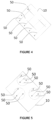
- a consolidation source of an additive manufacturing machine will discontinuously melt the powder along its path (as shown in the figures 2 to 5 ).
- the breakable zone therefore includes a multitude of solid portions which do not belong to the same block, as opposed to a porous part made in one piece.
- the solid portions of the breakable zone 10 have a polygonal section and/or a curvilinear section.
- the solid portions can be triangular or rectangular, or circular lamellae.
- these slats can be straight or wave-shaped.
- Each solid portion of the breakable zone 10 can have an area less than 10%, and preferably between 1% and 5%, of an area of the breakable zone 10. This arrangement makes it possible to guarantee optimal maintenance of the part during its manufacturing and optimal breakability during extraction of the part.
- a sum of the areas of the solid portions can be between 30% and 75% of the area of the breakable zone 10.
- the gap between lamella is the result of an increase between 300 and 500% in the vector difference between two scans of the beam of the energy source compared to that used to produce the reference structure which is the zone of anchoring. This arrangement does not allow overlap between the melting/sintering baths.
- the result obtained is for example in the form of independent strips.
- This arrangement allows the breakable zone 10 to present a structure sufficiently resistant to the forces generated during manufacturing, while presenting a fragility linked to its fine structure making it possible to easily separate the part 100 manually and thus facilitate the separation between the part 100. and the porous zone 20.
- the breakable zone 10 has for example a thickness E10 less than 15% of a total thickness E1 of the support 1.
- the thickness E10 is less than or equal to 10% of the total thickness E1.
- the thickness E10 is between 5% and 10% of the total thickness E1.
- Zone 20 is produced using a reduced volume energy density during melting or sintering by the beam scans of the energy source of the additive manufacturing machine.
- zone 20 is porous.
- This porous structure 20 provides sufficient strength to withstand the forces associated with manufacturing.
- zone 20 has a porous structure whose porosity is between 0.5 and 5%, preferably between 1 and 2%. It is recalled that the percentage of porosity of a structure is the ratio between the volume of voids and the total volume of the porous structure.
- the intermediate zone 20 has a thickness E20 of between 60% and 95% of the total thickness E1 of the support 1.
- the thickness E20 is between 70% and 90% of the total thickness E1 of the support 1.
- the support 1 has an anchoring zone 30. This is an advantageous arrangement, according to other embodiments, the support 1 could only have a breakable zone 10 and a zone intermediate 20.
- the anchoring zone 30 is intended to ensure good grip of the support 1 on a manufacturing plate of an additive manufacturing machine.
- the anchoring zone 30 is produced with a volume energy density substantially similar to that used to produce the part 100. This arrangement allows the anchoring zone 30 to be particularly resistant and to hang on a plate of an additive manufacturing machine.
- the anchoring zone 30 has a thickness E30 less than 30% of a total thickness E1 of the support 1.
- the thickness E30 is less than or equal to 20% of the total thickness E1.
- the invention proposes a process for additive manufacturing of a part 100.
- additive manufacturing we mean, for example, a manufacturing process by deposition of a powder bed in which layers of powder are superimposed. Then, each layer of powder is melted locally according to the plane of the part 100 to be manufactured (in a conventional manner the fusion can be carried out by an electron beam or a laser). The part 100 is thus manufactured by incrementation, that is to say a superposition, of different layers.
- additive manufacturing by powder bed deposition consists of producing three-dimensional objects by consolidating selected zones on successive layers of powder material (metal powder, ceramic powder, etc.).
- the consolidated areas correspond to successive sections of the three-dimensional object.
- the consolidation is done, for example, layer by layer, by a selective total or partial fusion carried out with a consolidation source (high-power laser beam, electron beam, etc.).
- the process begins with the manufacture of the support 1 and possibly the part 100
- the stacked areas of support 1 are made in the following order: anchoring area 30 (if applicable), then intermediate area 20 and breakable area 10.
- the intervector space for creating the anchoring zone is between 30 and 100 ⁇ m.
- this parameter can be increased between 130 and 200%.
- this same parameter can be increased between 300 and 500%.
- the volume energy density is modified by varying the intervector space.
- the intervector space parameter corresponds to the gap between two successive scans, and can be easily increased without prejudice to the production time of the part 100
- the volume energy density of energy necessary to manufacture the breakable zone 10 is between 10% of the density of volume energy necessary to manufacture the part and 25% of the volume energy density necessary to manufacture part 100.
- the volume energy density necessary to manufacture the breakable zone 10 is between 14% of the volume energy density necessary to manufacture the part and 20% of the volume energy density necessary to manufacture the part. piece 1.
- the consolidation source intermittently emits an energy beam.
- the vectors 50 represent the paths on which the consolidation source emits a beam (and therefore melts the powder).
- FIG 4 represents a stack of crossed lamellae which are orthogonally oriented. Thus the paths of the vectors 50 are intersecting in a plane representation.
- the volume energy density necessary to manufacture the intermediate zone 20 can be between 15% of the volume energy density necessary to manufacture the part and 60% of the volume energy density necessary to manufacture the part. piece 100.
- the volume energy density necessary to manufacture the intermediate zone 20 can be between 22% of the volume energy density necessary to manufacture the part and 50% of the volume energy density necessary to manufacture part 100.
- the volume energy density necessary to manufacture the anchoring zone 30 is substantially equal to the volume energy density necessary to manufacture the part 100 (within plus or minus 10%).
Landscapes
- Engineering & Computer Science (AREA)
- Manufacturing & Machinery (AREA)
- Chemical & Material Sciences (AREA)
- Materials Engineering (AREA)
- Mechanical Engineering (AREA)
- Physics & Mathematics (AREA)
- Plasma & Fusion (AREA)
- Optics & Photonics (AREA)
- Automation & Control Theory (AREA)
- Ceramic Engineering (AREA)
- Powder Metallurgy (AREA)
- Handling Of Sheets (AREA)
Claims (14)
- Stützstruktur (1) für die additive Fertigung, welche auf einer Platte einer Maschine zur additiven Fertigung einen durch additive Fertigung hergestellten Stapel umfasst, welcher aufweist:- einerseits einen trennbaren Bereich (10) mit lamellarer Struktur, der mehrere voneinander beabstandete massive Abschnitte umfasst, die nicht zum gleichen Block gehören, wobei der trennbare Bereich (10) zum Halten eines Teils (100), das durch additive Fertigung hergestellt werden soll, während dessen Fertigung eingerichtet ist, und- andererseits zwischen der Platte und dem Bereich mit trennbarer Struktur (10) einen einstückigen Zwischenbereich mit poröser Struktur (20).
- Stützstruktur (1) für die additive Fertigung nach Anspruch 1, wobei die massiven Abschnitte des trennbaren Bereichs (10) einen polygonalen Querschnitt und/oder einen gekrümmten Querschnitt aufweisen.
- Stützstruktur (1) für die additive Fertigung nach einem der Ansprüche 1 oder 2, wobei jeder massive Abschnitt des trennbaren Bereichs (10) eine Fläche aufweist, die weniger als 10 % und vorzugsweise zwischen 1 % und 5 % einer Fläche des trennbaren Bereichs (10) beträgt.
- Stützstruktur (1) für die additive Fertigung nach Anspruch 3, wobei eine Summe der Flächen der massiven Abschnitte zwischen 30 und 75 % der Fläche des trennbaren Bereichs (10) beträgt.
- Stützstruktur (1) für die additive Fertigung nach einem der vorhergehenden Ansprüche, wobei der Zwischenbereich eine Porosität zwischen 0,5 und 5 %, vorzugsweise zwischen 1 und 2 % aufweist.
- Stützstruktur (1) für die additive Fertigung nach einem der vorhergehenden Ansprüche, welche außerdem einen Verankerungsbereich (30) umfasst, der dazu eingerichtet ist, auf einer Fertigungsplatte angehängt zu werden, wobei der Verankerungsbereich (30) eine Dichte aufweist, die größer als die Dichte des porösen Zwischenbereichs (20) und/oder des trennbaren Bereichs (10) ist.
- Stützstruktur (1) für die additive Fertigung nach einem der vorhergehenden Ansprüche, wobei der trennbare Bereich eine Dicke aufweist, die kleiner als 15 % einer Gesamtdicke der Stützstruktur ist.
- Stützstruktur (1) für die additive Fertigung nach einem der vorhergehenden Ansprüche, wobei der Zwischenbereich (20) eine Dicke aufweist, die zwischen 60 % und 95 % einer Gesamtdicke der Stützstruktur (1) beträgt.
- Stützstruktur (1) für die additive Fertigung nach einem der vorhergehenden Ansprüche in Kombination mit Anspruch 3, wobei der Verankerungsbereich (30) eine Dicke aufweist, die kleiner oder gleich 30 % einer Gesamtdicke der Stützstruktur ist.
- Verfahren zur additiven Fertigung eines Teils (100) durch Verfestigung ausgewählter Bereiche auf aufeinander folgenden Schichten eines pulverförmigen Materials durch eine Verfestigungsquelle, wobei zuvor eine Stützstruktur (1) für die additive Fertigung durch additive Fertigung, auf einer Platte einer Maschine zur additiven Fertigung, eines Stapels hergestellt wird, welcher aufweist:- einerseits einen trennbaren Bereich mit lamellarer Struktur, der mehrere voneinander beabstandete massive Abschnitte umfasst, die nicht zum gleichen Block gehören, wobei der trennbare Bereich zum Halten eines Teils (100), das durch additive Fertigung hergestellt werden soll, während dessen Fertigung eingerichtet ist und mit einer Energiedichte hergestellt wird, die zwischen 10 % und 25 %, vorzugsweise zwischen 14 und 20 %, der Volumenenergiedichte bei der Fertigung des Teils (100) beträgt, und- andererseits zwischen der Platte und dem Bereich mit trennbarer Struktur einen einstückigen Zwischenbereich mit poröser Struktur.
- Verfahren nach Anspruch 10, wobei, wenn ein Vektorzwischenraum einem Abstand zwischen zwei Vektoren der Trajektorie eines Strahls der Verfestigungsquelle entspricht, der Vektorzwischenraum bei der Fertigung des trennbaren Bereichs zwischen 300 und 500 % des Vektorzwischenraumes bei der Fertigung des Teils beträgt.
- Verfahren nach einem der Ansprüche 10 und 11, wobei der poröse Zwischenbereich (20) mit eine Volumenenergiedichte hergestellt wird, die zwischen 15 % und 60 %, vorzugsweise 22 und 50 %, der Volumenenergiedichte bei der Fertigung des Teils (100) beträgt.
- Verfahren nach Anspruch 12, wobei der Vektorzwischenraum bei der Fertigung des porösen Bereichs zwischen 130 und 190 % des Vektorzwischenraumes bei der Fertigung des Teils beträgt.
- Verfahren nach einem der Ansprüche 10 bis 13, wobei die Volumenenergiedichte bei der Fertigung des Verankerungsbereichs (30) zwischen 90 % und 110 % der Volumenenergiedichte beträgt, die bei der Fertigung des Teils (100) verwendet wird.
Applications Claiming Priority (2)
| Application Number | Priority Date | Filing Date | Title |
|---|---|---|---|
| FR1910687A FR3101275B1 (fr) | 2019-09-27 | 2019-09-27 | Procédé de fabrication additive |
| PCT/FR2020/051674 WO2021058920A1 (fr) | 2019-09-27 | 2020-09-25 | Procede de fabrication additive |
Publications (2)
| Publication Number | Publication Date |
|---|---|
| EP4034372A1 EP4034372A1 (de) | 2022-08-03 |
| EP4034372B1 true EP4034372B1 (de) | 2024-05-29 |
Family
ID=69024393
Family Applications (1)
| Application Number | Title | Priority Date | Filing Date |
|---|---|---|---|
| EP20790379.0A Active EP4034372B1 (de) | 2019-09-27 | 2020-09-25 | Additives herstellungsverfahren |
Country Status (7)
| Country | Link |
|---|---|
| US (1) | US20220324028A1 (de) |
| EP (1) | EP4034372B1 (de) |
| JP (1) | JP2022550341A (de) |
| KR (1) | KR20220070272A (de) |
| CN (1) | CN114521159A (de) |
| FR (1) | FR3101275B1 (de) |
| WO (1) | WO2021058920A1 (de) |
Families Citing this family (2)
| Publication number | Priority date | Publication date | Assignee | Title |
|---|---|---|---|---|
| IT202100015218A1 (it) * | 2021-06-10 | 2022-12-10 | Torino Politecnico | Procedimento di fabbricazione additiva e prodotto ottenibile tramite il procedimento |
| CN119703086B (zh) * | 2024-12-30 | 2025-11-18 | 华中科技大学 | 一种多孔金属零件的间断扫描式激光选区熔化成形方法 |
Family Cites Families (7)
| Publication number | Priority date | Publication date | Assignee | Title |
|---|---|---|---|---|
| CN107000321A (zh) * | 2014-10-01 | 2017-08-01 | 瑞尼斯豪公司 | 增材制造设备和方法 |
| EP3278908B1 (de) * | 2016-08-02 | 2020-01-08 | Siemens Aktiengesellschaft | Stützstruktur, verfahren zur bereitstellung davon und verfahren zur additiven fertigung |
| FR3055564B1 (fr) * | 2016-09-08 | 2020-07-31 | Safran | Procede de fabrication d'une piece en materiau electroconducteur par fabrication additive |
| CN106807944B (zh) * | 2017-01-17 | 2018-11-30 | 华中科技大学 | 一种基于粉末床的倾斜结构增材制造工艺方法 |
| CN106825567B (zh) * | 2017-01-22 | 2018-12-11 | 清华大学 | 电子束选区熔化与电子束切割复合的增材制造方法 |
| WO2018160807A1 (en) * | 2017-03-02 | 2018-09-07 | Velo3D, Inc. | Three-dimensional printing of three dimensional objects |
| US20190047222A1 (en) * | 2017-08-14 | 2019-02-14 | Formlabs, Inc. | Techniques for producing thermal support structures in additive fabrication and related systems and methods |
-
2019
- 2019-09-27 FR FR1910687A patent/FR3101275B1/fr not_active Expired - Fee Related
-
2020
- 2020-09-25 WO PCT/FR2020/051674 patent/WO2021058920A1/fr not_active Ceased
- 2020-09-25 EP EP20790379.0A patent/EP4034372B1/de active Active
- 2020-09-25 US US17/763,951 patent/US20220324028A1/en not_active Abandoned
- 2020-09-25 JP JP2022519186A patent/JP2022550341A/ja active Pending
- 2020-09-25 KR KR1020227013992A patent/KR20220070272A/ko not_active Withdrawn
- 2020-09-25 CN CN202080067391.2A patent/CN114521159A/zh active Pending
Also Published As
| Publication number | Publication date |
|---|---|
| FR3101275B1 (fr) | 2022-07-08 |
| KR20220070272A (ko) | 2022-05-30 |
| JP2022550341A (ja) | 2022-12-01 |
| FR3101275A1 (fr) | 2021-04-02 |
| CN114521159A (zh) | 2022-05-20 |
| WO2021058920A1 (fr) | 2021-04-01 |
| US20220324028A1 (en) | 2022-10-13 |
| EP4034372A1 (de) | 2022-08-03 |
Similar Documents
| Publication | Publication Date | Title |
|---|---|---|
| EP3370901B1 (de) | Verfahren zur generativen fertigung eines teils, insbesondere eines verkleidungselement für eine reifenform, unter verwendung von pulver | |
| EP2879818B1 (de) | Verfahren zur herstellung eines dreidimensionalen objekts | |
| EP3174653B1 (de) | Verfahren zur pulverbasierten generativen fertigung einer komponente, insbesondere einer formenden formungsreifenformauskleidung, mit einem zugehörigen verstärkungselement | |
| EP2909019B1 (de) | Formelement einer form für einen reifen mit mehreren löchern | |
| WO2021058920A1 (fr) | Procede de fabrication additive | |
| EP3509774B1 (de) | Verfahren zur herstellung eines teils aus elektrisch leitendem material durch generative fertigung | |
| FR2996800A1 (fr) | Element moulant d'un moule pour pneumatique comportant une zone poreuse | |
| EP3969213B1 (de) | Generatives herstellungsverfahren für ein metallwerkstück | |
| FR3030321B1 (fr) | Fabrication par fusion laser d'une piece telle qu'un boitier d'un dispositif optronique ou avionique et pieces associees | |
| EP3484683A1 (de) | Hybridlamelle zur auskleidung einer reifenform | |
| FR2984786A1 (fr) | Procede de fabrication d'une aube creuse | |
| EP3715024B1 (de) | Additives herstellungsverfahren eines bauteils | |
| EP0820821B1 (de) | Verfahren zum Ausschneiden eines Zuschnittteils aus einer Blechplatte | |
| EP3445515B1 (de) | Generatives herstellungsverfahren eines mehrstufigen werkstücks mit variablem querschnitt umfassend einen überhängenden teil | |
| WO2020240128A1 (fr) | Procédé de fabrication additive d'une pièce comprenant une étape de fabrication d'un support mixte | |
| EP3481570A2 (de) | Verfahren zur generativen fertigung mit materialentfernung zwischen zwei schichten | |
| FR3026034A1 (fr) | Procede de fabrication d'une piece creuse par fusion selective de poudre | |
| FR3017142A1 (fr) | Element de construction comportant au moins deux blocs | |
| BE1005424A6 (fr) | Element de construction presentant une structure cellulaire et procede de fabrication de cet element de construction. | |
| FR3099402A1 (fr) | Prefiliere de coextrusion multi-voies possedant un raidisseur traversant monolithique pouvant etre obtenu par fabrication additive | |
| EP3924122A1 (de) | Verfahren zur generativen fertigung mit trennung über eine zerbrechliche zone | |
| FR3158459A1 (fr) | Support pour fabrication additive d’une pièce par fusion laser sur lit de poudre | |
| FR3167062A1 (fr) | Piece pour aeronef comprenant une surface en plafond autosupportée | |
| EP4444495A2 (de) | Werkzeugelektrode zur herstellung von dichtungsschlitzen in einem cmc-material mittels edm | |
| EP2546427A1 (de) | Blockbaustein |
Legal Events
| Date | Code | Title | Description |
|---|---|---|---|
| STAA | Information on the status of an ep patent application or granted ep patent |
Free format text: STATUS: UNKNOWN |
|
| STAA | Information on the status of an ep patent application or granted ep patent |
Free format text: STATUS: THE INTERNATIONAL PUBLICATION HAS BEEN MADE |
|
| PUAI | Public reference made under article 153(3) epc to a published international application that has entered the european phase |
Free format text: ORIGINAL CODE: 0009012 |
|
| STAA | Information on the status of an ep patent application or granted ep patent |
Free format text: STATUS: REQUEST FOR EXAMINATION WAS MADE |
|
| 17P | Request for examination filed |
Effective date: 20220415 |
|
| AK | Designated contracting states |
Kind code of ref document: A1 Designated state(s): AL AT BE BG CH CY CZ DE DK EE ES FI FR GB GR HR HU IE IS IT LI LT LU LV MC MK MT NL NO PL PT RO RS SE SI SK SM TR |
|
| DAV | Request for validation of the european patent (deleted) | ||
| DAX | Request for extension of the european patent (deleted) | ||
| GRAP | Despatch of communication of intention to grant a patent |
Free format text: ORIGINAL CODE: EPIDOSNIGR1 |
|
| STAA | Information on the status of an ep patent application or granted ep patent |
Free format text: STATUS: GRANT OF PATENT IS INTENDED |
|
| RIC1 | Information provided on ipc code assigned before grant |
Ipc: B22F 3/105 20060101ALI20231031BHEP Ipc: B33Y 30/00 20150101ALI20231031BHEP Ipc: B33Y 10/00 20150101ALI20231031BHEP Ipc: B22F 10/47 20210101ALI20231031BHEP Ipc: B22F 10/28 20210101ALI20231031BHEP Ipc: B22F 3/11 20060101ALI20231031BHEP Ipc: B29C 64/40 20170101AFI20231031BHEP |
|
| INTG | Intention to grant announced |
Effective date: 20231204 |
|
| RIN1 | Information on inventor provided before grant (corrected) |
Inventor name: AUBRUN, ANTHONY Inventor name: PICARD, ALEXIS Inventor name: RUIZ, MICHEL |
|
| GRAJ | Information related to disapproval of communication of intention to grant by the applicant or resumption of examination proceedings by the epo deleted |
Free format text: ORIGINAL CODE: EPIDOSDIGR1 |
|
| STAA | Information on the status of an ep patent application or granted ep patent |
Free format text: STATUS: REQUEST FOR EXAMINATION WAS MADE |
|
| GRAP | Despatch of communication of intention to grant a patent |
Free format text: ORIGINAL CODE: EPIDOSNIGR1 |
|
| STAA | Information on the status of an ep patent application or granted ep patent |
Free format text: STATUS: GRANT OF PATENT IS INTENDED |
|
| INTC | Intention to grant announced (deleted) | ||
| INTG | Intention to grant announced |
Effective date: 20240221 |
|
| RIN1 | Information on inventor provided before grant (corrected) |
Inventor name: AUBRUN, ANTHONY Inventor name: PICARD, ALEXIS Inventor name: RUIZ, MICHEL |
|
| GRAS | Grant fee paid |
Free format text: ORIGINAL CODE: EPIDOSNIGR3 |
|
| GRAA | (expected) grant |
Free format text: ORIGINAL CODE: 0009210 |
|
| STAA | Information on the status of an ep patent application or granted ep patent |
Free format text: STATUS: THE PATENT HAS BEEN GRANTED |
|
| AK | Designated contracting states |
Kind code of ref document: B1 Designated state(s): AL AT BE BG CH CY CZ DE DK EE ES FI FR GB GR HR HU IE IS IT LI LT LU LV MC MK MT NL NO PL PT RO RS SE SI SK SM TR |
|
| REG | Reference to a national code |
Ref country code: CH Ref legal event code: EP |
|
| REG | Reference to a national code |
Ref country code: IE Ref legal event code: FG4D Free format text: LANGUAGE OF EP DOCUMENT: FRENCH |
|
| REG | Reference to a national code |
Ref country code: DE Ref legal event code: R096 Ref document number: 602020031724 Country of ref document: DE |
|
| REG | Reference to a national code |
Ref country code: NL Ref legal event code: FP |
|
| REG | Reference to a national code |
Ref country code: LT Ref legal event code: MG9D |
|
| PG25 | Lapsed in a contracting state [announced via postgrant information from national office to epo] |
Ref country code: IS Free format text: LAPSE BECAUSE OF FAILURE TO SUBMIT A TRANSLATION OF THE DESCRIPTION OR TO PAY THE FEE WITHIN THE PRESCRIBED TIME-LIMIT Effective date: 20240929 |
|
| PG25 | Lapsed in a contracting state [announced via postgrant information from national office to epo] |
Ref country code: BG Free format text: LAPSE BECAUSE OF FAILURE TO SUBMIT A TRANSLATION OF THE DESCRIPTION OR TO PAY THE FEE WITHIN THE PRESCRIBED TIME-LIMIT Effective date: 20240529 |
|
| PG25 | Lapsed in a contracting state [announced via postgrant information from national office to epo] |
Ref country code: HR Free format text: LAPSE BECAUSE OF FAILURE TO SUBMIT A TRANSLATION OF THE DESCRIPTION OR TO PAY THE FEE WITHIN THE PRESCRIBED TIME-LIMIT Effective date: 20240529 Ref country code: FI Free format text: LAPSE BECAUSE OF FAILURE TO SUBMIT A TRANSLATION OF THE DESCRIPTION OR TO PAY THE FEE WITHIN THE PRESCRIBED TIME-LIMIT Effective date: 20240529 |
|
| PG25 | Lapsed in a contracting state [announced via postgrant information from national office to epo] |
Ref country code: GR Free format text: LAPSE BECAUSE OF FAILURE TO SUBMIT A TRANSLATION OF THE DESCRIPTION OR TO PAY THE FEE WITHIN THE PRESCRIBED TIME-LIMIT Effective date: 20240830 |
|
| REG | Reference to a national code |
Ref country code: AT Ref legal event code: MK05 Ref document number: 1690288 Country of ref document: AT Kind code of ref document: T Effective date: 20240529 |
|
| PG25 | Lapsed in a contracting state [announced via postgrant information from national office to epo] |
Ref country code: ES Free format text: LAPSE BECAUSE OF FAILURE TO SUBMIT A TRANSLATION OF THE DESCRIPTION OR TO PAY THE FEE WITHIN THE PRESCRIBED TIME-LIMIT Effective date: 20240529 |
|
| PG25 | Lapsed in a contracting state [announced via postgrant information from national office to epo] |
Ref country code: AT Free format text: LAPSE BECAUSE OF FAILURE TO SUBMIT A TRANSLATION OF THE DESCRIPTION OR TO PAY THE FEE WITHIN THE PRESCRIBED TIME-LIMIT Effective date: 20240529 |
|
| PG25 | Lapsed in a contracting state [announced via postgrant information from national office to epo] |
Ref country code: PL Free format text: LAPSE BECAUSE OF FAILURE TO SUBMIT A TRANSLATION OF THE DESCRIPTION OR TO PAY THE FEE WITHIN THE PRESCRIBED TIME-LIMIT Effective date: 20240529 |
|
| PG25 | Lapsed in a contracting state [announced via postgrant information from national office to epo] |
Ref country code: LV Free format text: LAPSE BECAUSE OF FAILURE TO SUBMIT A TRANSLATION OF THE DESCRIPTION OR TO PAY THE FEE WITHIN THE PRESCRIBED TIME-LIMIT Effective date: 20240529 |
|
| PG25 | Lapsed in a contracting state [announced via postgrant information from national office to epo] |
Ref country code: PL Free format text: LAPSE BECAUSE OF FAILURE TO SUBMIT A TRANSLATION OF THE DESCRIPTION OR TO PAY THE FEE WITHIN THE PRESCRIBED TIME-LIMIT Effective date: 20240529 Ref country code: NO Free format text: LAPSE BECAUSE OF FAILURE TO SUBMIT A TRANSLATION OF THE DESCRIPTION OR TO PAY THE FEE WITHIN THE PRESCRIBED TIME-LIMIT Effective date: 20240829 Ref country code: LV Free format text: LAPSE BECAUSE OF FAILURE TO SUBMIT A TRANSLATION OF THE DESCRIPTION OR TO PAY THE FEE WITHIN THE PRESCRIBED TIME-LIMIT Effective date: 20240529 Ref country code: IS Free format text: LAPSE BECAUSE OF FAILURE TO SUBMIT A TRANSLATION OF THE DESCRIPTION OR TO PAY THE FEE WITHIN THE PRESCRIBED TIME-LIMIT Effective date: 20240929 Ref country code: HR Free format text: LAPSE BECAUSE OF FAILURE TO SUBMIT A TRANSLATION OF THE DESCRIPTION OR TO PAY THE FEE WITHIN THE PRESCRIBED TIME-LIMIT Effective date: 20240529 Ref country code: GR Free format text: LAPSE BECAUSE OF FAILURE TO SUBMIT A TRANSLATION OF THE DESCRIPTION OR TO PAY THE FEE WITHIN THE PRESCRIBED TIME-LIMIT Effective date: 20240830 Ref country code: FI Free format text: LAPSE BECAUSE OF FAILURE TO SUBMIT A TRANSLATION OF THE DESCRIPTION OR TO PAY THE FEE WITHIN THE PRESCRIBED TIME-LIMIT Effective date: 20240529 Ref country code: ES Free format text: LAPSE BECAUSE OF FAILURE TO SUBMIT A TRANSLATION OF THE DESCRIPTION OR TO PAY THE FEE WITHIN THE PRESCRIBED TIME-LIMIT Effective date: 20240529 Ref country code: BG Free format text: LAPSE BECAUSE OF FAILURE TO SUBMIT A TRANSLATION OF THE DESCRIPTION OR TO PAY THE FEE WITHIN THE PRESCRIBED TIME-LIMIT Effective date: 20240529 Ref country code: AT Free format text: LAPSE BECAUSE OF FAILURE TO SUBMIT A TRANSLATION OF THE DESCRIPTION OR TO PAY THE FEE WITHIN THE PRESCRIBED TIME-LIMIT Effective date: 20240529 Ref country code: RS Free format text: LAPSE BECAUSE OF FAILURE TO SUBMIT A TRANSLATION OF THE DESCRIPTION OR TO PAY THE FEE WITHIN THE PRESCRIBED TIME-LIMIT Effective date: 20240829 |
|
| PG25 | Lapsed in a contracting state [announced via postgrant information from national office to epo] |
Ref country code: DK Free format text: LAPSE BECAUSE OF FAILURE TO SUBMIT A TRANSLATION OF THE DESCRIPTION OR TO PAY THE FEE WITHIN THE PRESCRIBED TIME-LIMIT Effective date: 20240529 |
|
| PG25 | Lapsed in a contracting state [announced via postgrant information from national office to epo] |
Ref country code: EE Free format text: LAPSE BECAUSE OF FAILURE TO SUBMIT A TRANSLATION OF THE DESCRIPTION OR TO PAY THE FEE WITHIN THE PRESCRIBED TIME-LIMIT Effective date: 20240529 |
|
| PG25 | Lapsed in a contracting state [announced via postgrant information from national office to epo] |
Ref country code: CZ Free format text: LAPSE BECAUSE OF FAILURE TO SUBMIT A TRANSLATION OF THE DESCRIPTION OR TO PAY THE FEE WITHIN THE PRESCRIBED TIME-LIMIT Effective date: 20240529 |
|
| PG25 | Lapsed in a contracting state [announced via postgrant information from national office to epo] |
Ref country code: RO Free format text: LAPSE BECAUSE OF FAILURE TO SUBMIT A TRANSLATION OF THE DESCRIPTION OR TO PAY THE FEE WITHIN THE PRESCRIBED TIME-LIMIT Effective date: 20240529 Ref country code: SK Free format text: LAPSE BECAUSE OF FAILURE TO SUBMIT A TRANSLATION OF THE DESCRIPTION OR TO PAY THE FEE WITHIN THE PRESCRIBED TIME-LIMIT Effective date: 20240529 |
|
| PG25 | Lapsed in a contracting state [announced via postgrant information from national office to epo] |
Ref country code: SM Free format text: LAPSE BECAUSE OF FAILURE TO SUBMIT A TRANSLATION OF THE DESCRIPTION OR TO PAY THE FEE WITHIN THE PRESCRIBED TIME-LIMIT Effective date: 20240529 |
|
| PG25 | Lapsed in a contracting state [announced via postgrant information from national office to epo] |
Ref country code: RO Free format text: LAPSE BECAUSE OF FAILURE TO SUBMIT A TRANSLATION OF THE DESCRIPTION OR TO PAY THE FEE WITHIN THE PRESCRIBED TIME-LIMIT Effective date: 20240529 Ref country code: EE Free format text: LAPSE BECAUSE OF FAILURE TO SUBMIT A TRANSLATION OF THE DESCRIPTION OR TO PAY THE FEE WITHIN THE PRESCRIBED TIME-LIMIT Effective date: 20240529 Ref country code: DK Free format text: LAPSE BECAUSE OF FAILURE TO SUBMIT A TRANSLATION OF THE DESCRIPTION OR TO PAY THE FEE WITHIN THE PRESCRIBED TIME-LIMIT Effective date: 20240529 Ref country code: CZ Free format text: LAPSE BECAUSE OF FAILURE TO SUBMIT A TRANSLATION OF THE DESCRIPTION OR TO PAY THE FEE WITHIN THE PRESCRIBED TIME-LIMIT Effective date: 20240529 Ref country code: SM Free format text: LAPSE BECAUSE OF FAILURE TO SUBMIT A TRANSLATION OF THE DESCRIPTION OR TO PAY THE FEE WITHIN THE PRESCRIBED TIME-LIMIT Effective date: 20240529 Ref country code: SK Free format text: LAPSE BECAUSE OF FAILURE TO SUBMIT A TRANSLATION OF THE DESCRIPTION OR TO PAY THE FEE WITHIN THE PRESCRIBED TIME-LIMIT Effective date: 20240529 |
|
| REG | Reference to a national code |
Ref country code: DE Ref legal event code: R097 Ref document number: 602020031724 Country of ref document: DE |
|
| REG | Reference to a national code |
Ref country code: DE Ref legal event code: R119 Ref document number: 602020031724 Country of ref document: DE |
|
| PLBE | No opposition filed within time limit |
Free format text: ORIGINAL CODE: 0009261 |
|
| STAA | Information on the status of an ep patent application or granted ep patent |
Free format text: STATUS: NO OPPOSITION FILED WITHIN TIME LIMIT |
|
| PG25 | Lapsed in a contracting state [announced via postgrant information from national office to epo] |
Ref country code: SI Free format text: LAPSE BECAUSE OF FAILURE TO SUBMIT A TRANSLATION OF THE DESCRIPTION OR TO PAY THE FEE WITHIN THE PRESCRIBED TIME-LIMIT Effective date: 20240529 Ref country code: MC Free format text: LAPSE BECAUSE OF FAILURE TO SUBMIT A TRANSLATION OF THE DESCRIPTION OR TO PAY THE FEE WITHIN THE PRESCRIBED TIME-LIMIT Effective date: 20240529 |
|
| REG | Reference to a national code |
Ref country code: CH Ref legal event code: PL |
|
| 26N | No opposition filed |
Effective date: 20250303 |
|
| REG | Reference to a national code |
Ref country code: NL Ref legal event code: MM Effective date: 20241001 |
|
| PG25 | Lapsed in a contracting state [announced via postgrant information from national office to epo] |
Ref country code: LU Free format text: LAPSE BECAUSE OF NON-PAYMENT OF DUE FEES Effective date: 20240925 |
|
| GBPC | Gb: european patent ceased through non-payment of renewal fee |
Effective date: 20240925 |
|
| PG25 | Lapsed in a contracting state [announced via postgrant information from national office to epo] |
Ref country code: NL Free format text: LAPSE BECAUSE OF NON-PAYMENT OF DUE FEES Effective date: 20241001 |
|
| PG25 | Lapsed in a contracting state [announced via postgrant information from national office to epo] |
Ref country code: DE Free format text: LAPSE BECAUSE OF NON-PAYMENT OF DUE FEES Effective date: 20250401 |
|
| PG25 | Lapsed in a contracting state [announced via postgrant information from national office to epo] |
Ref country code: GB Free format text: LAPSE BECAUSE OF NON-PAYMENT OF DUE FEES Effective date: 20240925 |
|
| REG | Reference to a national code |
Ref country code: BE Ref legal event code: MM Effective date: 20240930 |
|
| PG25 | Lapsed in a contracting state [announced via postgrant information from national office to epo] |
Ref country code: BE Free format text: LAPSE BECAUSE OF NON-PAYMENT OF DUE FEES Effective date: 20240930 Ref country code: IT Free format text: LAPSE BECAUSE OF NON-PAYMENT OF DUE FEES Effective date: 20240925 |
|
| PG25 | Lapsed in a contracting state [announced via postgrant information from national office to epo] |
Ref country code: CH Free format text: LAPSE BECAUSE OF NON-PAYMENT OF DUE FEES Effective date: 20240930 |
|
| PG25 | Lapsed in a contracting state [announced via postgrant information from national office to epo] |
Ref country code: IE Free format text: LAPSE BECAUSE OF NON-PAYMENT OF DUE FEES Effective date: 20240925 |
|
| PG25 | Lapsed in a contracting state [announced via postgrant information from national office to epo] |
Ref country code: SE Free format text: LAPSE BECAUSE OF FAILURE TO SUBMIT A TRANSLATION OF THE DESCRIPTION OR TO PAY THE FEE WITHIN THE PRESCRIBED TIME-LIMIT Effective date: 20240529 |
|
| PGFP | Annual fee paid to national office [announced via postgrant information from national office to epo] |
Ref country code: FR Payment date: 20250820 Year of fee payment: 6 |
|
| PG25 | Lapsed in a contracting state [announced via postgrant information from national office to epo] |
Ref country code: PT Free format text: LAPSE BECAUSE OF NON-PAYMENT OF DUE FEES Effective date: 20240529 |
|
| PG25 | Lapsed in a contracting state [announced via postgrant information from national office to epo] |
Ref country code: CY Free format text: LAPSE BECAUSE OF FAILURE TO SUBMIT A TRANSLATION OF THE DESCRIPTION OR TO PAY THE FEE WITHIN THE PRESCRIBED TIME-LIMIT; INVALID AB INITIO Effective date: 20200925 |
|
| PG25 | Lapsed in a contracting state [announced via postgrant information from national office to epo] |
Ref country code: HU Free format text: LAPSE BECAUSE OF FAILURE TO SUBMIT A TRANSLATION OF THE DESCRIPTION OR TO PAY THE FEE WITHIN THE PRESCRIBED TIME-LIMIT; INVALID AB INITIO Effective date: 20200925 |