EP4033744B1 - Apparatus and method for improving the reproducibility of images - Google Patents
Apparatus and method for improving the reproducibility of images Download PDFInfo
- Publication number
- EP4033744B1 EP4033744B1 EP21152490.5A EP21152490A EP4033744B1 EP 4033744 B1 EP4033744 B1 EP 4033744B1 EP 21152490 A EP21152490 A EP 21152490A EP 4033744 B1 EP4033744 B1 EP 4033744B1
- Authority
- EP
- European Patent Office
- Prior art keywords
- pixel
- line
- pixels
- light
- pixel array
- Prior art date
- Legal status (The legal status is an assumption and is not a legal conclusion. Google has not performed a legal analysis and makes no representation as to the accuracy of the status listed.)
- Active
Links
Images


Classifications
-
- H—ELECTRICITY
- H04—ELECTRIC COMMUNICATION TECHNIQUE
- H04N—PICTORIAL COMMUNICATION, e.g. TELEVISION
- H04N1/00—Scanning, transmission or reproduction of documents or the like, e.g. facsimile transmission; Details thereof
- H04N1/024—Details of scanning heads ; Means for illuminating the original
- H04N1/028—Details of scanning heads ; Means for illuminating the original for picture information pick-up
- H04N1/03—Details of scanning heads ; Means for illuminating the original for picture information pick-up with photodetectors arranged in a substantially linear array
- H04N1/031—Details of scanning heads ; Means for illuminating the original for picture information pick-up with photodetectors arranged in a substantially linear array the photodetectors having a one-to-one and optically positive correspondence with the scanned picture elements, e.g. linear contact sensors
-
- H—ELECTRICITY
- H04—ELECTRIC COMMUNICATION TECHNIQUE
- H04N—PICTORIAL COMMUNICATION, e.g. TELEVISION
- H04N1/00—Scanning, transmission or reproduction of documents or the like, e.g. facsimile transmission; Details thereof
- H04N1/04—Scanning arrangements, i.e. arrangements for the displacement of active reading or reproducing elements relative to the original or reproducing medium, or vice versa
- H04N1/19—Scanning arrangements, i.e. arrangements for the displacement of active reading or reproducing elements relative to the original or reproducing medium, or vice versa using multi-element arrays
- H04N1/191—Scanning arrangements, i.e. arrangements for the displacement of active reading or reproducing elements relative to the original or reproducing medium, or vice versa using multi-element arrays the array comprising a one-dimensional [1D] array
- H04N1/1911—Simultaneously or substantially simultaneously scanning picture elements on more than one main scanning line, e.g. scanning in swaths
- H04N1/1912—Scanning main scanning lines which are spaced apart from one another in the sub-scanning direction
-
- H—ELECTRICITY
- H04—ELECTRIC COMMUNICATION TECHNIQUE
- H04N—PICTORIAL COMMUNICATION, e.g. TELEVISION
- H04N1/00—Scanning, transmission or reproduction of documents or the like, e.g. facsimile transmission; Details thereof
- H04N1/024—Details of scanning heads ; Means for illuminating the original
- H04N1/028—Details of scanning heads ; Means for illuminating the original for picture information pick-up
- H04N1/02815—Means for illuminating the original, not specific to a particular type of pick-up head
- H04N1/02895—Additional elements in the illumination means or cooperating with the illumination means, e.g. filters
-
- H—ELECTRICITY
- H04—ELECTRIC COMMUNICATION TECHNIQUE
- H04N—PICTORIAL COMMUNICATION, e.g. TELEVISION
- H04N1/00—Scanning, transmission or reproduction of documents or the like, e.g. facsimile transmission; Details thereof
- H04N1/04—Scanning arrangements, i.e. arrangements for the displacement of active reading or reproducing elements relative to the original or reproducing medium, or vice versa
- H04N1/0402—Scanning different formats; Scanning with different densities of dots per unit length, e.g. different numbers of dots per inch (dpi); Conversion of scanning standards
- H04N1/0408—Different densities of dots per unit length
- H04N1/0414—Different densities of dots per unit length in the sub scanning direction
-
- H—ELECTRICITY
- H04—ELECTRIC COMMUNICATION TECHNIQUE
- H04N—PICTORIAL COMMUNICATION, e.g. TELEVISION
- H04N2201/00—Indexing scheme relating to scanning, transmission or reproduction of documents or the like, and to details thereof
- H04N2201/0077—Types of the still picture apparatus
- H04N2201/0081—Image reader
Definitions
- the invention relates to a device and a method for improving the reproducibility of recordings, by means of which a reduction or removal of the moiré effect is made possible.
- the moiré effect is an optical effect in which the superimposition of regular grids or patterns creates a periodic grid or pattern that has special structures that are not present in any of the individual grids and that vary when the way they are superimposed is changed. This effect can occur when at least two grids that can be relatively finely designed overlap. It is a type of optical interference that can create certain grids that usually appear quite coarse in their design.
- the moiré effect can be compared to an optical illusion.
- the moiré effect can occur in image processing whenever two or more grids overlap, for example when at least one banknote is captured using at least one image sensor, when motifs with a regular structure are recorded. An image sensor can also record individual pixels using a specific grid. When processing banknotes, three regular grids can occur.
- a banknote can have locally parallel lines.
- regular scanning can take place in the transport direction.
- regular scanning in the line direction can also take place.
- the locally parallel lines and the regular scanning in the transport direction can cause a moiré effect if, for example, a scan has gaps.
- the locally parallel lines and the regular scanning in the line direction mean that, for example, no moiré effect is generated if a scan in the line direction has no gaps or only small, negligible gaps.
- FIG. 1A, FIG. 1B and FIG. 1C Each of these images shows a (always the same) 50-euro banknote 100, which was recorded or captured in three different positions using an image sensor, for example a conventional contact image sensor.
- a 50-euro banknote 100 has a bridge arch below it, see the arrows 102a and 102b in the FIG. 1A, FIG. 1B, FIG. 1C , a plurality of line structures running in one direction.
- the moiré effect can arise in very different patterns as an interaction between the structures on the motif and the scanning structure, which at least one image sensor, for example a conventional contact image sensor of a scanner, has (see, for example, the arrows 102a and 102b in the FIG. 1A, FIG. 1B and FIG. 1C ). Due to the different angles or small shifts in the scanning at which the 50-euro banknote is recorded by the image sensor, different unwanted moiré effect patterns are formed. If the 50-euro banknote is recorded with a fine pattern, the grid of the image sensor and the grid created by the fine pattern of the banknote affect each other.
- FIG. 1A, FIG. 1B and FIG. 1C occur mainly due to the different slant of banknotes that often occurs in practice and/or the different phase position of the scanning grid to the periodic lines and a pixel area that is too small compared to the scanning step. In principle, pixels that are too large compared to the scanning step can also lead to moiré effects.
- RGB color values may not be able to be measured at the same position due to time-multiplexing at, for example, 100 dots per inch (dpi), which can lead to reduced accuracy of color tone measurements, for example to spotting in the recorded image.
- a Nyquist criterion may also not be met in a transport direction of a banknote, for example at a resolution of 50 dpi, which is recorded at different slant angles, which can lead to low accuracy in the printing area. Consequently, reproducibility of image recordings, for example of banknotes, cannot be guaranteed.
- WO 99/35618 A1 discloses a currency validator for evaluating banknotes comprising a housing combining an inlet for receiving banknotes, a scanning path along which a received banknote is moved for evaluation, and a drive arrangement associated with the scanning path. Scanners of different types are provided in removable modules, whereby the scanners and their position can be varied by replacing the module with another module.
- the US 2005/045809 A1 discloses a photosensor assembly having multiple rows of photosensors sharing a charge transfer register. Charges from one row of photosensors are transferred to the charge transfer register through another row of photosensors, and charges from both rows of photosensors are optionally added in the charge transfer register.
- the photosensors in the two rows may have different light collection areas
- the device and the method are intended to enable a moiré-free image of, for example, banknotes.
- the device and the method described here are intended to enable a moiré-free image of banknotes by adapting a scan in the transport direction.
- the device and the method described here are intended to improve image reproducibility.
- the device and the method described here are intended to make the images of a banknote independent of different diagonal lines and/or different scanning locations.
- a plurality of recording types can be set using the device and the method described here.
- a larger scanning area can be achieved using the device and the method described here.
- the reproducibility of the images of a banknote can be improved using the device and the method described here.
- a signal-to-noise ratio can be improved by means of the device and the method described herein.
- the light source may be on the same (incident light measurement) and/or the opposite (transmitted light measurement) side as the image plane with respect to the object plane.
- the transmitted light measurement may be a bright field and/or dark field configuration.
- the light-sensitive line pixel array may comprise at least one photodiode line pixel array.
- a number of row pixel arrays may be less than a number of pixels in each row pixel array.
- a contact image sensor may have a line pixel array with, for example, about 800 pixels in a line and may have, for example, two lines.
- the object may be a security, such as a banknote or a check.
- the device may be a securities reader, for example a banknote and/or check reader.
- the drive device can have a plurality of rollers and at least one drive motor.
- the drive motor can be set up to drive at least one roller, for example a drive roller, such that at least one object can be driven along the transport direction on the guide device in the object plane and transported by means of guide rollers.
- the at least one light source can be a light-emitting diode (LED) light source, for example a monochrome LED or an RGB LED for color illumination of an object in the object plane.
- the light source can have a plurality of light sources in a direction perpendicular or transverse to a transport direction.
- the at least one light source can have at least one diode rod with light output.
- the at least one light source can be configured as a light guide with light output, which can be fed laterally with LEDs of different wavelengths.
- a rod lens can be, for example, a cylindrical lens.
- At least one rod lens can be designed as a gradient index lens. In various embodiments, at least one rod lens can be designed as a gradient index rod lens.
- the at least one rod lens can have a cylindrical shape in which the two end surfaces are polished and the lateral surface can be optically irrelevant.
- a rod lens can be available with different optical materials, for example with glasses such as quartz glass, but also with crystalline materials or plastic.
- the rod lenses can have a diameter in a value range of about 0.1 millimeters to 2 millimeters and, for example, a length range of 2 millimeters to 50 millimeters.
- a rod lens can have at least a simple structure and enable easy handling and can be coated using various coatings.
- At least one rod lens can be configured as a SELFOC ® microlens, for example as a flat gradient index lens.
- the refractive index change in the material can be generated by ion exchange.
- at least one lens can be configured as a linear array of gradient index lenses or as multiple parallel arrays.
- a rod lens can image an object strip in the object plane onto an image strip in the image plane.
- a one-dimensional line pixel array may be a photosensitive CMOS array.
- a one-dimensional line pixel array may be a photosensitive CCD array.
- the contact image sensor and/or the light-sensitive line pixel array may have a compact design with a resolution of up to about 600 dpi.
- a resolution of a line array may be determined by means of a pixel pitch.
- the device may further comprise a housing.
- the at least one light source can be operated by means of time-multiplexed illumination.
- the color blue can be illuminated
- the color green can be illuminated
- the color red can be illuminated
- the color infrared can be illuminated.
- a row for example a CMOS row or a CCD row
- CMOS row or a CCD row can measure at least one pixel value and export received data in analog or digital form, for example to a control device and/or to a memory.
- the contact image sensor and/or the light-sensitive line pixel array may comprise at least two light-sensitive lines.
- the two lines may be independent of each other or jointly, for example by means of a Control device.
- the control device can supply and operate a first row with a supply voltage or current.
- the control device can supply and operate a second row with a supply voltage or current.
- the control device can operate the first and second rows individually.
- the control device can, for example, switch off a row or set it to a ground potential in order to save energy, for example.
- three rows, four rows, five rows or even more rows can also be provided.
- the contact image sensor and/or the light-sensitive line pixel array may have a resolution of approximately 50 dpi or 100 dpi or 200 dpi and may be operated at the different resolutions.
- a device can have at least a plurality of contact image sensors, for example at least one pair of contact image sensors.
- the contact image sensors can be arranged adjacently along a transport direction of an object.
- the contact image sensors can each have a width such that they each completely detect or cover an object to be examined, for example a check or a banknote.
- the at least one pair of contact image sensors can be operable by means of incident light operation.
- the contact image sensor and/or the light-sensitive line pixel array may have a resolution of approximately 100 dpi or 200 dpi or 300 dpi or 600 dpi and may be operated at the different resolutions.
- the contact image sensor and/or the light-sensitive line pixel array can be operated using an analog binning method.
- an analog binning method a charge that is collected in the potential wells can be physically combined by a plurality of pixels.
- capacitances can be connected in parallel and read out, for example, by a control device.
- the analog binning method is preferably used in the devices and methods described herein. Using the analog binning method, a data reduction can be achieved because fewer pixels have to be read out. Furthermore, using the analog Binning can shorten line readout time and reduce the amount of data, which can reduce the need for memory and computing power. Analog binning also improves the signal-to-noise ratio.
- the contact image sensor and/or the light-sensitive line pixel array can be operated using a digital binning method.
- a digital binning method pixel values can be read out from the pixels, digitized, added and, for example, optimally averaged.
- the contact image sensor and/or the light-sensitive line pixel array can be operated using a physical binning method to achieve data reduction, for example.
- a physical binning method With the physical binning method, fewer pixels have to be read out, which can shorten the line readout time and reduce the amount of data, which can reduce the need for memory and computing power.
- a readout time for a line can typically be three times shorter and banknotes can therefore be transported more quickly in a device described herein.
- a resolution of 200 dpi may be required for check processing according to regulations.
- control device can read each line individually or several lines approximately simultaneously.
- a line can be configured as a CMOS line scan camera.
- moiré-free images can be made possible by means of a 200 dots per inch contact image sensor and/or a light-sensitive line pixel array if a line is binned in 100 dpi mode and scanning in the transport direction also takes place at a resolution of 100 dpi.
- a binning process results in a resolution of 300 dpi, 200 dpi, 100 dpi, etc. in a line
- moiré-free scanning with the same resolution as in the line may be possible.
- control device may comprise a memory in which at least one pixel value of a plurality of pixel values of at least one row and/or both rows can be stored.
- the plurality of one-dimensional line pixel arrays may be fixedly positioned, for example on a housing of the device, and the object, for example a check or a banknote, may be transported in a narrow gap, for example in a value range of about 0.1 mm to about 5 mm, for example in a value range of about 0.15 mm to about 3 mm, for example in a value range of about 0.2 mm to about 1.5 mm.
- a depth of field of a contact image sensor and/or a light-sensitive line pixel array can be in a value range of about 0.05 millimeters to about 5 millimeters, for example in a value range of about 0.075 millimeters to about 3 millimeters, for example in a value range of about 0.1 millimeters to about 1.6 millimeters.
- each line pixel array comprises a plurality of pixels, and each pixel comprises at least one photodiode, for example a light-sensitive photodiode, in CMOS construction for detecting a pixel value of the light emitted from the light source.
- the contact image sensor and/or the light-sensitive line pixel array may be configured to have two lines or one-dimensional line pixel arrays, each having a plurality of pixels.
- control device may be configured to read out at least one pixel value by controlling at least one pixel in a one-dimensional pixel array.
- control device may comprise at least one processor and/or a field programmable gate array (FPGA).
- FPGA field programmable gate array
- the contact image sensor and/or the light-sensitive line pixel array can be configured to comprise a two-dimensional pixel array line, each pixel of which can be individually controlled by the control device.
- Various embodiments provide a device for improving the reproducibility of recordings, in which at least a first line pixel array and a second line pixel array of the plurality of line pixel arrays are constructed identically.
- the first line pixel array and the second line pixel array can have the same number of pixels.
- the pixel size of the pixels of the first line pixel array and the second line pixel array can be approximately the same size, for example the same size.
- Various embodiments provide a device for improving the reproducibility of recordings, in which at least a second line pixel array of the plurality of line pixel arrays in the transport direction of the object is longer, for example by 10% percent up to a factor of 10 longer, for example up to a factor of 7.5, than a first line pixel array of the plurality of line pixel arrays in the transport direction of the object.
- a first line can have a plurality of pixels of the same size.
- An adjacent line can have pixels of different widths, for example pixels that are twice as wide as pixels in the first line.
- a second line can have a pixel sequence of: pixels with pixel width of two pixels, pixels with a pixel width of one pixel, pixels with a pixel width of one pixel, pixels with a pixel width of two pixels. This sequence can repeat in the second row.
- a pixel in a third row, can have a pixel width of: pixels with a pixel width of three pixels. This pixel width can repeat in the third row.
- a pixel in a fourth row, can have a pixel width of six pixels. This width can repeat in the fourth row.
- a device for improving the reproducibility of recordings in which at least one pixel in at least one line pixel array can be wider than a pixel in at least one further line pixel array.
- a pixel in a first line pixel array can be wider, for example by a factor of about 1.5 to about a factor of 3.5, for example by a factor of 2, relative to a corresponding pixel in a second line pixel array.
- a pixel width in a first line can be twice as wide relative to a pixel width in a second line.
- Various embodiments provide a device for improving the reproducibility of recordings, in which a sensitivity over the transport path can be approximately constant, for example constant.
- control device is further configured to operate the first line pixel array and the second line pixel array independently of one another, and in which the control device is configured to connect the second line pixel array to the first line pixel array and vice versa.
- Various embodiments provide an apparatus for improving the reproducibility of recordings, in which the majority of the line pixel arrays have a resolution in the direction transverse to the transport direction of 200 dpi.
- Various embodiments provide a device for improving the reproducibility of recordings, in which a line pixel array (7a) has a resolution in the direction transverse to the transport direction (8) of 200 dpi and a second line pixel array (7b) has a resolution in the direction transverse to the transport direction (8) of 100 dpi.
- a pixel of the plurality of line pixel arrays has a size in a value range of about 150 micrometers by about 150 micrometers, for example in a value range of about 130 micrometers by about 130 micrometers, for example in a value range of about 127 micrometers by 127 micrometers.
- control device is further configured, in a case where the object is at least a check, to set a resolution of the first line pixel array to 200 dpi, to deactivate the second line pixel array, to control the first line pixel array, and to read out the pixel values of the first line pixel array.
- control device is further configured, in the case where the object is at least one check, to reduce a speed of at least one check in the transport direction by means of a transport device, so that a check can be transported more slowly in the transport direction, for example to achieve a 200 dpi resolution in the transport direction.
- control device is further configured, in a case where the object is at least one banknote, to set a resolution of the first line pixel array and the second line pixel array to 100 dpi, to activate the first and the second line pixel array, to physically combine at least one charge collected in potential wells of two neighboring pixels in the first line pixel array and to read out pixel values, at least one charge collected in potential wells of two neighboring pixels in the second line pixel array corresponding to the two neighboring pixels in the first line pixel array, physically summarize and read pixel values, and provide a pixel value based on the read pixel values for further processing.
- control device is configured to set a resolution of the first line pixel array and the second line pixel array to a value between about 90 dpi to about 130 dpi, for example about 100 dpi.
- control device configured to combine pixel values of two adjacent pixels of a first line pixel array and at least one pixel value of an adjacent pixel of a second line pixel array by means of an analog binning method, and to provide a pixel value based on the combined pixel values for further processing.
- control device configured to combine two pixel values of two adjacent pixels of a first line pixel array and one pixel value of an adjacent pixel of a second line pixel array by means of an analog 3-binning method, and to provide a pixel value based on the combined pixel values for further processing.
- control device is further configured to combine pixel values of two adjacent pixels of the first line pixel array and pixel values of two adjacent pixels of the second line pixel array, which correspond to the two adjacent pixels of the first line pixel array, by means of an analog 2x2 binning method, and to provide at least one pixel value based on the combined pixel values for further processing.
- Various embodiments provide a device for improving the reproducibility of recordings, in which a higher light sensitivity per virtual pixel can be achieved and a signal-to-noise ratio can be improved.
- control device is further configured to activate the first and the second line pixel array, to read out at least a first pixel value of a first pixel of the first line pixel array and a first pixel value of a first pixel of the second line pixel array, to read out at least a second pixel value of the second pixel of the first line pixel array and a second pixel value of the second pixel of the second line pixel array, and to calculate a mean value from the first pixel values and the second pixel values using a line averaging acquisition method and to provide a pixel value for further processing.
- control device can be configured to switch during operation between a 100 dots per inch resolution and a 200 dots per inch resolution by means of software.
- Various embodiments provide a device for improving the reproducibility of recordings, in which the device has at least a second light source for illuminating the object, wherein the second light source is arranged on a side opposite the light source with respect to the plurality of rod lenses, and/or the rod lenses are gradient index rod lenses.
- the light source can illuminate an object, for example, from an angle of approximately 50 degrees to the transport plane, and the second light source can illuminate the object, for example, from an angle of approximately 60 degrees to the transport plane.
- the second light source can be arranged symmetrically to the light source with respect to the plurality of rod lenses, for example at the same angle, in an angle range of approximately 50 to approximately 60 degrees, to the transport direction.
- a device for improving the reproducibility of images which can have a plurality of light sources.
- the device can be operated, for example, in a reflected light mode, in which at least one light source or several light sources is/are positioned on the side as the image plane and is/are operated to illuminate at least one object that can be transported in the device.
- the device can be operated, for example, in a transmitted light mode, in which at least one light source is on one side, which is positioned and operated on an opposite side of the image plane with respect to the object in order to illuminate the object.
- the light source and/or can be operated, for example, in a brightfield transmitted light mode.
- the light source can be operated, for example, in a darkfield transmitted light mode.
- at least one light source can be arranged on the same side (incident light measurement) as the image plane with respect to the object plane and/or at least one light source can be arranged on the opposite side (transmitted light measurement) as the image plane.
- Various embodiments provide an apparatus for improving the reproducibility of recordings in which the rod lenses may be gradient index rod lenses.
- Various embodiments provide a device for improving the reproducibility of recordings, in which the device has a plurality of rows of rod lenses arranged in series, in which the rows of rod lenses are arranged parallel to one another, and in which the rows are each arranged transversely to the transport device.
- Various embodiments provide a device for improving the reproducibility of recordings, in which at least a first row of the plurality of rows of rod lenses is arranged adjacent to at least one further row of the plurality of rod lenses, in which the first row of rod lenses and the further row of rod lenses are arranged in a direction transverse to the transport direction of the object at a predefined distance from one another, for example in a value range of approximately 1 micrometer to 10 micrometers, for example at a distance of 2 micrometers, for example 4 micrometers, for example 7 micrometers, for example 9 micrometers, and are arranged displaced from one another transversely to the transport direction by a predefined distance, for example by approximately half a diameter of a rod lens, for example in a value range of approximately 100 micrometers to approximately 200 micrometers, for example 130 micrometers to approximately 170 micrometers, for example at a distance of approximately 150 micrometers, and/or at least one intermediate space between a rod lens and an adjacent rod lens with at least a filling material,
- Various embodiments provide a device for improving the reproducibility of recordings, in which a distance of a rod lens of a first row to a rod lens of a second row has a value range of about 0 millimeters to about 5 millimeters.
- Various embodiments provide a method for improving the reproducibility of recordings.
- the method comprises guiding at least one object in an object plane by means of a guide device.
- the method comprises transporting the object in the object plane in a transport direction by means of at least one drive device.
- the method comprises illuminating the object by means of at least one light source of a contact image sensor.
- the method comprises at least partially scattering a light emitted by the light source from the object to a plurality of rod lenses of the contact image sensor.
- the method comprises imaging at least a portion of the light scattered by the object by means of the plurality of rod lenses arranged between the object plane and an image plane and in a row along a direction transverse to the transport direction of the object to at least one light-sensitive line pixel array of the contact image sensor.
- the method comprises controlling at least the light source and/or the light-sensitive line pixel array by means of a control device, wherein the light-sensitive line pixel array comprises a plurality of one-dimensional line pixel arrays, each of which extends along the direction transverse to the transport direction of the object, is arranged parallel to one another and adjacent to one another, and wherein each line pixel array has a length transverse to the transport direction of the object that completely covers the object to be detected.
- the method comprises detecting the light imaged by the rod lenses by means of at least one region of a light-sensitive line pixel array that is arranged in the image plane.
- the method comprises merging at least individual pixel values of the plurality of one-dimensional line pixel arrays.
- the method comprises providing a pixel value for further processing by means of the control device.
- the method for improving the reproducibility of recordings can be designed to operate the light source in a time-division multiplex method.
- the method for improving the reproducibility of images may be arranged to illuminate the object sequentially with a plurality of colors and/or infrared and/or ultraviolet.
- the merging of at least individual pixel values of the method can, for example, comprise merging by means of an analog binning method.
- the merging by means of an analog binning method can, for example, comprise 2x2 binning, in which two pixel values from a first line pixel array and two pixel values from a second line pixel array are merged.
- the merging by means of an analog binning method can, for example, comprise a 3-binning method, in which pixel values of two adjacent pixels are merged in a first line pixel array and a pixel value of a corresponding pixel is merged in a second line pixel array.
- the merging of at least individual pixel values of the method can, for example, comprise digital merging, for example digital binning.
- the method for improving the reproducibility of recordings may comprise, in a case where the object is at least a check, setting a resolution of the first line pixel array to 200 dpi by means of a control device, deactivating the second line pixel array by means of a control device, controlling the first line pixel array by means of a control device, and reading out the pixel values of the first line pixel array by means of a control device.
- the method for improving the reproducibility of images may, in a case where an object is at least one banknote, set a resolution of the first line pixel array and the second line pixel array to 100 dpi by means of the control device, activate the first and the second line pixel array by means of the control device, physically combine at least one charge which is stored in potential wells of two adjacent pixels in the first row pixel array and reading out pixel values by means of the control device, physically combining at least one charge which is collected in potential wells of two adjacent pixels in the second row pixel array corresponding to the two adjacent pixels in the first row pixel array and reading out pixel values by means of the control device, and providing a pixel value based on the read out pixel values for further processing by means of the control device.
- the method for improving the reproducibility of recordings can comprise merging pixel values of two adjacent pixels of the first line pixel array and at least one pixel value of an adjacent pixel of the second line pixel array by means of an analog or digital binning method by means of a control device, and providing a pixel value based on the combined pixel values for further processing by means of a control device.
- the method for improving the reproducibility of recordings can comprise activating the first and second line pixel arrays by means of a control device, reading out at least a first pixel value of a first pixel of the first line pixel array and a first pixel value of a first pixel of the second line pixel array by means of a control device, reading out at least a second pixel value of the second pixel (7a_2) of the first line pixel array (7a) and a second pixel value of the second pixel (7b_2) of the second line pixel array (7b) by means of a control device, and calculating a mean value by means of a line averaging acquisition method from the first pixel values and the second pixel values by means of a control device and providing a pixel value for further processing by means of a control device, and/or switching during operation between a 100 dots per inch resolution and a 200 dots per inch resolution by means of software and/or by means of a control device.
- analog binning refers to a process in which charge, which can be collected in potential wells, from two or more pixels is physically combined. With analog binning, the readout speed for a line can be shortened.
- digital binning refers to a process in which individual pixel values are read out, digitized, added and possibly averaged.
- Line Averaging Acquisition Mode refers, for example, to an operating mode of a control device described herein and of a device and/or method described herein.
- a line acquisition can be carried out when both a first and a second line of a contact image sensor are exposed.
- pixel values of the first line and pixel values of the second line can be averaged or an average value can be formed.
- the averaging can proceed as follows: The value of pixel 1 in a first line A is added to the value of pixel 1 in a second line B and the sum of the pixel values is divided by the number 2. The result can be rounded up.
- the value of pixel 2 in the first line A is added to the value of pixel 2 in the second line B and the sum of the pixel values is divided by the number 2.
- the result can be rounded up.
- the value of pixel 3 in the first row A is added to the value of pixel 3 in the second row B and the sum of the pixel values is divided by the number 2.
- the result can be rounded up, and so on.
- the averaged values can then be transmitted by the Contact Image Sensor for further processing as if they came from a single row.
- the devices and methods described herein can provide moiré-free sensor data, which is a basis for reliable detection of stains, graffiti and other defacements. Graffiti are scribbles on banknotes. Because the reproducibility of the measurement is improved by the method described herein, even fine structures on the banknote can be better detected, such as a serial number, see-through register, barcode, clear text, micro-perforation, micro-printing, Omron rings, thin cracks and the color tone measurements become more accurate.
- CMOS or Complementary Metal Oxide Semiconductor refers to semiconductor devices in which both p-channel and n-channel MOSFETs can be used on a common substrate.
- a charge-coupled device array (CCD array) can also be used.
- contact image sensor or contact imaging sensor (CIS) used here refers to a cost-effective, CMOS-based technology for image sensors.
- a contact image sensor is usually a line sensor in which a number of light-sensitive points or pixels are arranged in a row. A tiny plastic lens can be located above each of these points. One lens can cover several pixels and/or one pixel can collect light from several lenses.
- the object to be detected can usually be illuminated using light source LEDs arranged parallel to the sensors - in the case of color scanners, using light source RGB LEDs. To capture the image, the sensor can require almost direct contact with the original.
- FIG. 1A, FIG. 1B and FIG. 1C show a schematic representation of moiré effects on one and the same 50-euro banknote 100 with different diagonal pull in the transport direction using a banknote reader.
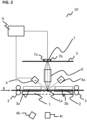
- FIG. 2 is a schematic representation of a device 10 for improving the reproducibility of recordings according to various embodiments.
- the device 10 for improving the reproducibility of recordings comprises a guide device 1 which is set up to guide at least one object 2 in the object plane 1a, at least one drive device 3 which is set up to transport the object 2 on the guide device 1 in the object plane 1a in a transport direction 8, at least one light source 4 for illuminating the object 2, an image plane 5, a plurality of rod lenses 6 which are arranged between the object plane 1a and the image plane 5 and in a row along a direction transverse to the transport direction 8 of the object 2, at least one light-sensitive line pixel array 7 of a contact image sensor which is arranged in the image plane 5, a control device 9 which is set up to control at least the light source 4 and/or the line pixel array 7 and to detect a signal generated by the line pixel array, wherein a light emitted by the light source 4 is at least partially scattered from the object 2 towards the rod lenses 6.
- each line pixel array 7a, 7b has a length transverse to the transport direction 8 of the object 2 which completely covers the object 2 to be detected.
- An object 2, for example a check or a banknote, can be transported from a first side by means of the drive device 3 along the object plane 1a or also in the opposite direction (bidirectional).
- the drive device 3 can have a plurality of rollers that can transport an object 2 in or against the transport direction 8. At least one roller can be driven by a motor.
- the device 10 can have a plurality of light sources 4, 4a, 4b, 4c, 4d. At least one light source can be used for incident light operation, for example the light sources 4 and 4a. At least one light source can be used for transmitted light operation, for example the light sources 4b and 4c. While the object 2 moves along the transport direction 8 at a predefined speed, the light sources 4, 4a emit at least one light with one or more defined wavelengths.
- the emitted light is partially absorbed by the object 2 located underneath and partially scattered or reflected in a direction towards the rod lenses 6.
- the light sources 4, 4a can be rod-shaped so that the light illuminates a strip of the object almost simultaneously.
- a portion of the scattered or reflected light is Rod lenses 6 are optically imaged onto the image plane 5 and a part falls onto the two adjacently arranged one-dimensional line pixel arrays 7a, 7b, as is exemplified in the FIG. 2 is shown.
- the device 10 shown may comprise a light source 4.
- at least one light source 4, 4a can be arranged at different angles to the object plane.
- the light source 4, 4a can be positioned at an angle to the object plane 1a in a value range of about 10 degrees to about 80 degrees, for example in a value range of about 15 degrees to about 75 degrees, for example at an angle of about 45 degrees to the object plane 1a.
- the light source 4 can be arranged at an angle of about 50 degrees and the second light source 4a at an angle of about 60 degrees to the object plane 1a.
- the light sources 4 and 4a can be arranged symmetrically with respect to the plurality of rod lenses.
- Simultaneous illumination can make the illumination more diffuse, or angle-dependent scattering can be evaluated by time multiplexing.
- the device 10 can be operated by means of incident light using at least the light source 4 and/or 4a.
- the device 10 can also be operated by means of a transmitted light mode, for example a bright field mode and/or a dark field mode.
- the device 10 can, for example, operate a light source 4b in a dark field transmitted light mode.
- the device 10 can, for example, operate a light source 4c in a bright field transmitted light mode.
- the light sources 4b, 4c can be arranged on a different side in relation to the object plane 1a compared to at least one of the light sources 4, 4a.
- the light source 4c can, for example, when operated as a bright field light source, be arranged on an optical axis of a rod lens 6, for example approximately below the FIG. 2
- the light source 4b can be arranged adjacent to the light source 4c and on the same side with respect to the object plane 1a.
- At least one of the light sources 4, 4a, 4b, 4c can be operated by means of time-multiplex illumination.
- the time-multiplex illumination method can be carried out with respect to a wavelength of illumination and/or between incident and transmitted light and/or with respect to an illumination angle.
- the control device 9 can operate the light sources 4 and 4a for a 940 nanometer (nm) incident light line simultaneously.
- the control device can, for example, also operate the light source 4c for a 940 nm transmitted light line
- the object can be illuminated with the color blue
- the object can be illuminated with green
- the object can be illuminated with red
- the object can be irradiated with infrared.
- the two rows 7a, 7b of the light-sensitive line pixel array 7, for example CMOS rows can measure at least one pixel value and the control device 9 can receive and export data in analog or digital form.
- the control device 9 can be housed in the device 10 or arranged decentrally.
- the guide device 1 can be transparent in a partial area, for example translucent, for example in a transmitted light operation of the device 10.
- the device 10 can further comprise guides 3a and 3b for guiding an object 2.
- the guides 3a and 3b can be arranged opposite to the guide device 1 in relation to an object 2.
- the guides 3a can be transparent in at least a partial area, for example translucent, for example in a transmitted light operation of the device 10, as shown schematically in the FIG. 2 In the area of the illumination and/or the optical imaging, parts of the guide device may be missing in order to enable the illumination and/or the optical imaging.
- the control device 9 is designed to operate the first line pixel array 7a and the second line pixel array 7b independently of one another and to connect the second line pixel array 7b to the first line pixel array 7a and vice versa.
- the majority of the line pixel arrays 7a, 7b have, for example, a resolution in the direction transverse to the transport direction 8 of 200 dpi.
- a pixel of the majority of line pixel arrays 7a, 7b can have a size of 127 micrometers by 127 micrometers.
- the control device 9 is configured, in a case where the object 2 is at least a check, to set a resolution of the first line pixel array 7a to 200 dpi, to deactivate the second line pixel array 7b, to control the first line pixel array 7a, and to read out the pixel values of the first line pixel array 7a.
- the control device 9 is further configured, in a case where the object 2 is at least one banknote, to set a resolution of the first line pixel array 7a and the second line pixel array 7b to 100 dpi, to activate the first and the second line pixel array 7a, 7b, to read out and summarize at least two pixel values of neighboring pixels 7a_1, 7a_2 in the first line pixel array 7a, to read out and summarize at least two pixel values of neighboring pixels 7b_1, 7b_2 corresponding to the two neighboring pixels 7a_1, 7a_2 in the first line pixel array 7a in the second line pixel array 7b, to summarize the two summarized neighboring pixels 7a_1, 7a_2 in the first line pixel array 7a and the two summarized neighboring pixels 7b_1, 7b_2 in the second line pixel array 7b, and provide a pixel value based on the aggregated pixel values for further processing.
- the control device 9 is further configured to combine pixel values of two adjacent pixels 7a_1, 7a_2 of the first line pixel array 7a and pixel values of two adjacent pixels 7b_1, 7b_2 of the second line pixel array 7b, which correspond to the two adjacent pixels 7a_1, 7a_2 of the first line pixel array 7a, by means of an analog 2x2 binning method, and to provide a pixel value based on the combined pixel values for further processing.
- the control device 9 is further configured to activate the first and second line pixel arrays 7a, 7b, to read out at least a first pixel value of a first pixel 7a_1 of the first line pixel array 7a and a first pixel value of a first pixel 7b_1 of the second line pixel array 7b, to read out at least a second pixel value of the second pixel 7a_2 of the first line pixel array 7a and a second pixel value of the second pixel 7b_2 of the second line pixel array 7b, and to calculate a mean value from the first pixel values and the second pixel values using a line averaging acquisition method and to provide a pixel value for further processing.
- the second light source 4a can be arranged as a reflected light source to the light source 4 in a mirrored manner with respect to a plane that runs perpendicular to the object plane 1, parallel to the rod lenses 6 and runs through a central optical axis of the rod lenses 6.
- the reflected light source 4a can be provided in such a way that it can be positioned at different angles to an object guide 1, for example in a value range of approximately 30 degrees to approximately 60 degrees, for example at an angle of approximately 45 degrees.
- at least a transmitted light source 4b, 4c can be provided.
- at least one light source can be operated as a transmitted light source.
- the transmitted light source can be arranged on an opposite side to the image plane with respect to a guide device 1.
- the device 10 has a row of rod lenses 6 or a plurality of rows of rod lenses 6 arranged in a row, wherein the rows of rod lenses 6 are arranged parallel to one another, and wherein the rows are each arranged transversely to the transport device 8.
- At least a first row of the plurality of rows of rod lenses 6 can be arranged adjacent to at least one further row of the plurality of rod lenses, wherein the first row of rod lenses 6 and the further row of rod lenses can be arranged in a direction transverse to the transport direction of the object 2 at a predefined distance from one another, for example in a value range of approximately 1 micrometer to 10 micrometers, for example at a distance of 2 micrometers, for example 4 micrometers, for example 7 micrometers, for example 9 micrometers, and can be arranged displaced from one another by a predefined distance, for example in a value range of approximately 0 micrometers to approximately 400 micrometers, for example 130 micrometers to approximately 340 micrometers, for example at a distance of approximately 190 micrometers, transverse to the transport direction 8, and/or at least one gap between a rod lens 6 and an adjacent rod lens can be filled with at least one filling material, for example black silicon wax or black silicon resin. be filled up.
- at least one filling material
- the device described herein can be operated by means of a method described herein for improving the reproducibility of recordings.
- the method can comprise: at least one of guiding at least one object 2 on a guide device 1 in an object plane 1a by means of the guide device 1, transporting the object 2 on the guide device 1 in the object plane 1a in a transport direction 8 by means of at least one drive device 3, illuminating the object 2 by means of at least one light source 4, at least partially scattering a light emitted by the light source 4 from the object 2 to the rod lenses 6, forwarding at least a portion of the light scattered by the object 2 by means of a plurality of rod lenses 6 which are arranged between the object plane 1a and an image plane 5 and are arranged in a row along a direction transverse to the transport direction 8 of the object 2, to form a light-sensitive line pixel array 7, controlling at least the light source 4 and/or the light-sensitive line pixel array 7 by means of a control device 9, wherein the light-sensitive line pixel array 7 has a plurality
- the transport direction 8 can also be in a direction to that in FIG. 2
- the device 10 can also be configured to transport the object 2 both in a first transport direction 8 and in a second transport direction that is opposite to the first transport direction.
- FIG. 3 is a schematic representation of a device 20 for improving the reproducibility of recordings according to various embodiments.
- the information relating to the FIG. 3 Device 20 described may have at least one feature or all features of the device described with respect to the FIG. 2 described device 10.
- the device described in the FIG. 3 illustrated reference numerals corresponding reference numerals which, in relation to the FIG. 2 be used.
- the device 20 in FIG. 3 has a plurality of light sources 4, 4a, 4b, 4c and 4d.
- a banknote or a check can be transported, for example, by means of a plurality of belts, as is shown for example in the FIG. 3
- the device 20 can be operated, for example, in a reflected light mode, in which at least one light source 4, 4a is operated to illuminate at least one object 2 which is in the Device 20 can be transported.
- the device 20 can be operated, for example, in a transmitted light mode, in which at least one light source 4b, 4c, 4d is operated to illuminate the object 2.
- the light source 4b and/or 4d can be operated, for example, in a dark field transmitted light mode.
- the light source 4c can be operated, for example, in a bright field transmitted light mode.
- at least one light source 4, 4a can be arranged on the same side (incident light measurement) with respect to the object plane and/or at least one light source 4b, 4c, 4d can be on the opposite side (transmitted light measurement) as the image plane.
- the arrangements of the light sources 4, 4a, 4b, 4c, 4d in the FIG. 3 illustrate a possible arrangement.
- the light sources 4, 4a, 4b, 4c, 4d can have other positions.
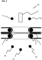
- FIG. 4A, FIG. 4B, FIG. 4C, FIG. 4D are schematic representations of a portion of a device and a method for improving the reproducibility of recordings according to various embodiments.
- the FIG. 4A, FIG. 4B, FIG. 4C and FIG. 4D each show a diagram that schematically illustrates a contact image sensor 10 with two one-dimensional line pixel arrays 7a, 7b according to various embodiments.
- the first line pixel array 7a has a plurality of pixels 7a_1, 7a_2.
- the second line pixel array 7b has a A plurality of pixels 7b_1, 7b_2.
- Each pixel of the plurality of pixels 7a_1, 7a_2, 7b_1, 7b_2 can be read out, for example, by means of the control device 9.
- FIG.4A shows a resting state of the contact image sensor 10 with two one-dimensional line pixel arrays 7a, 7b according to various embodiments.
- the Fig. 4B shows a first operating state (check operation) of the contact image sensor 10 with two one-dimensional line pixel arrays 7a, 7b according to various embodiments.
- the control device 9 is set up to set a resolution of the first line pixel array 7a to 200 dpi in a case where the object 2 is at least a check. Furthermore, the control device 9 deactivates the second line pixel array 7b.
- the control device 9 controls the first line pixel array 7a and reads out the pixel values of the first line pixel array 7a, for example in an intrinsic resolution.
- the FIG. 4C shows a second operating state (banknote operation) of the contact image sensor 10 with two one-dimensional line pixel arrays 7a, 7b according to various embodiments.
- the control device 9 is set up to set a resolution of the first line pixel array 7a and the second line pixel array 7b to 100 dpi in a case where the object 2 is at least one banknote.
- the control device 9 activates the first and the second line pixel array 7a, 7b and reads out at least two pixel values of neighboring pixels 7a_1, 7a_2 in the first line pixel array 7a and summarizes them.
- the control device 9 is further set up to read out and summarize at least two pixel values of neighboring pixels 7b_1, 7b_2 in the second line pixel array 7b that correspond to the two neighboring pixels 7a_1, 7a_2 in the first line pixel array 7a.
- the control device 9 is further configured to combine the two combined adjacent pixels 7a_1, 7a_2 in the first line pixel array 7a and the two combined adjacent pixels 7b_1, 7b_2 in the second line pixel array 7b, for example by means of a binning method, and to provide a pixel value based on the combined pixel values for further processing.
- control device 9 is further configured to combine pixel values of two adjacent pixels 7a_1, 7a_2 of the first line pixel array 7a and pixel values of two adjacent pixels 7b_1, 7b_2 of the second line pixel array 7b, which correspond to the two adjacent pixels 7a_1, 7a_2 of the first line pixel array 7a, using a 2x2 binning method and to provide a pixel value based on the combined pixel values for further processing.
- the control device operates the two lines at half resolution.
- the binning method enables a higher light sensitivity per virtual pixel and a signal-to-noise ratio can be improved and a line can be read out more quickly.
- control device 9 is further configured to activate the first and the second line pixel array 7a, 7b, to read out at least a first pixel value of a first pixel 7a_1 of the first line pixel array 7a and a first pixel value of a first pixel 7b_1 of the second line pixel array 7b.
- the control device 9 is further configured to read out at least a second pixel value of the second pixel 7a_2 of the first line pixel array 7a and a second pixel value of the second pixel 7b_2 of the second line pixel array 7b and to calculate an average value by means of a Line averaging acquisition method to calculate from the first pixel values and the second pixel values and to provide one pixel value each for further processing.
- the device and method for improving the reproducibility of images can enable one and the same contact image sensor with different resolutions to be operated with the same performance as a contact image sensor specifically designed for that resolution, without a significant increase in manufacturing costs due to higher quantities of that model.
- the resolution can be configured during operation without a loss of performance compared to a contact image sensor which is only designed for the corresponding resolution or with two differently designed contact image sensors, which increases the costs, space requirements and risk of jams. Such switching is necessary if the banknote reader must also be used for check operation and/or if color channels with different resolutions are operated in the lighting sequence.
- the control device 9 can switch between the Figures 4B and 4C described operating modes. For example, it can be determined that the object is a check. The control device 9 can then switch to the operating mode described in relation to the FIG. 4B described operating mode. For example, it can be determined that the object is at least one banknote. The control device 9 can then switch to the operating mode described with respect to the FIG. 4C described operating mode.
- the operating modes can also change within the color sequence.
- the individual pixel values can be read out and converted by means of an analog-digital converter 11, as described in the FIG. 4A to FIG. 4D is shown schematically.
- FIG.4D shows a further operating state of a contact image sensor with two one-dimensional line pixel arrays 7a, 7b according to various embodiments.
- at least one pixel in at least one line pixel array can be wider transversely to the transport direction than a pixel in at least one further line pixel array.
- a pixel in a first line pixel array can be wider in relation to a corresponding pixel in a second line pixel array by, for example, about a factor of 1.5 to about a factor of 3.5, for example by a factor of 2.
- a pixel width transversely to the transport direction of an object in a first line can be twice as wide in relation to a pixel width in a second line.
- a first pixel of a line can have a width transversely to the transport direction of an object that two pixels in an adjacent line together have transversely to the transport direction.
- a width transversely to the transport direction of a pixel in a first line pixel array 7a and of a pixel in a second line pixel array 7b can be, for example, 127 micrometers.
- a width transverse to the transport direction of a pixel in a first line pixel array 7a can be, for example, 127 micrometers and a width transverse to the transport direction of a pixel in a second line pixel array 7b can be, for example, 254 micrometers.
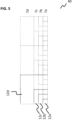
- FIG. 5 is a schematic representation of a partial region 40 of a device for improving the reproducibility of recordings according to various embodiments.
- FIG. 5 illustrates, by way of example, a partial area 40 of a moiré-free contact image sensor in 100, 200, 300 and 600 dots per inch resolution.
- a device 10, 20 for improving the reproducibility of recordings at least one pixel in at least one line pixel array can be made wider than a pixel in at least one further line pixel array.
- a first line has a plurality of pixels of the same size (see pixel sequence in line 7a in FIG. 5 ).
- An adjacent line has pixels of different widths, namely pixels that are twice as wide as pixels of the first line.
- a second line has a pixel sequence of: pixels with a pixel width of two pixels, pixels with a pixel width of one pixel of the first line, pixels with a pixel width of one pixel, pixels with a pixel width of two pixels (see pixel sequence in line 7b in FIG. 5 ).
- This sequence repeats in the second line.
- a pixel has a pixel width of: Pixel with pixel width of three pixels in the first line. This pixel width can repeat in the third line (see pixel sequence in line 7c in FIG. 5 ).
- a pixel can have a pixel width of six pixels of the first line. This width can be repeated in the fourth line (see pixel sequence in line 7d in FIG. 5 ).
- the height of the pixels in the fourth row can be three pixel heights of the pixels in the first row.
- a lower row 7a can be designed for 600 dots per inch, see 12a. If a resolution of 300 dots per inch is to be recorded, a pixel area can be enlarged to the pixel area 12b by means of an analog binning. If a resolution of 200 dots per inch is to be recorded, a pixel area can be enlarged to a pixel area 12c by means of an analog binning. If a resolution of 100 dots per inch is to be recorded, a pixel area can be enlarged to a pixel area 12d by means of an analog binning. In other words, pixels can be combined in such a way that at least one larger pixel can be created.
- a plurality of pixels in at least one row or in a plurality of rows can be combined in such a way that a respective resolution, for example 100 dots per inch, can be realized.
- a respective resolution for example 100 dots per inch
- two adjacent pixels can be connected together in a first row and corresponding pixels can be connected together in a second row (see 12b), which in turn can be connected together as shown schematically in the FIG. 5
- the pixel area 12b, 12c, 12d shown can be individually connected or combined using an analog binning process.
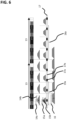
- FIG. 6 is a schematic representation of a portion of a device and a method for improving the reproducibility of recordings according to various embodiments.
- the FIG. 6 illustrates an illumination sequence in which a contact image sensor can be designed for a resolution of 200 dpi, for example.
- the FIG. 6 Contact Image Sensor illustrated may be, for example, a Contact Image Sensor described herein.
- the paths 13 in the FIG. 6 can have a length of about 1016 micrometers.
- a pitch, ie a step size between neighboring pixels transverse to the transport direction can be, for example, about 127 micrometers in the one-dimensional pixel array 7a, 7b.
- An extension of a pixel in the transport direction 8 cannot then exceed 127 micrometers, otherwise the resolution in the transport direction would become worse. This means that in the transport direction 8 the pixel 7a instantly captures 127 micrometers if the rod lens 6 could image perfectly.
- the distance 14a for example with a length of about 127 micrometers, represents a distance at a time when at least one of the light sources 4, 4a, 4b, 4c, 4d, for example an LED, is switched on.
- the object 2 moves in the transport direction 8.
- the recording location is shifted by approximately 1016 micrometers divided by 12 (see the line 14b in FIG. 6 ).
- the sensitivity of an ideal contact image sensor 10 and/or a line pixel array 7 in the transport direction 8 is given by the trapezoids A in the FIG. 6
- the pixel size in the transport direction 8 in a contact image sensor and/or in a light-sensitive line pixel array can effectively be only about 99 micrometers. Therefore, the distances 15a, 15b in FIG. 6 shorter.
- duty cycle is understood to be a ratio between the illumination duration and the inverse line rate.
- An inverse line rate can be understood as a line time, for example as 1,016 micrometers/(12*v), where v indicates a speed. Therefore, the sections 15a and 15b cover a smaller area than desired, or the flanks of the trapezoid B are steeper.
- the real sensitivity of, for example, a green channel in the transport direction 8 is determined by the trapezoids B in the FIG.
- a sensitivity of, for example, a green channel in the transport direction 8 as indicated by the trapezoids C in the FIG. 6 The gaps in sensitivity, as in trapezoids A and B in the FIG. 6 observed, have now practically disappeared.
- the second pixel in the transport direction 8 is somewhat longer than the first pixel in the transport direction 8, for example by a factor in a range from about 1.5 to about 1.7, for example by a factor of about 1.57, the sensitivity over the transport path 8 (or over the banknote) can be approximately constant. This means that a moiré effect can no longer occur.
- FIG. 7 is a flow chart schematically illustrating a method for improving the reproducibility of recordings according to various embodiments.
- the method for improving the reproducibility of recordings can comprise at least one of the following: guiding at least one object in an object plane by means of a guide device (S701); transporting the object in the object plane in a transport direction by means of at least one drive device (S702); illuminating the object by means of at least one light source of a contact image sensor (S703); at least partially scattering a light emitted by the light source from the object to a plurality of rod lenses of the contact image sensor (S704); imaging at least a portion of the light scattered by the object by means of the plurality of rod lenses arranged between the object plane and an image plane and in a row along a direction transverse to the transport direction of the object to at least one light-sensitive line pixel array of the contact image sensor (S705); controlling at least the light source and/or the light-sensitive line pixel array by means of a control device (S706), wherein the light-sensitive line pixel array has a plurality of one-dimensional line pixel arrays, each of
- the method may further comprise features relating to the FIG. 1 , FIG. 2 , FIG. 3 , FIG. 4 , FIG. 5 and or FIG. 6
- the advantages described in relation to the embodiments of the device described herein also relate to the embodiments of the method described herein and vice versa.
Landscapes
- Engineering & Computer Science (AREA)
- Multimedia (AREA)
- Signal Processing (AREA)
- Inspection Of Paper Currency And Valuable Securities (AREA)
- Investigating Or Analysing Materials By Optical Means (AREA)
- Investigating Materials By The Use Of Optical Means Adapted For Particular Applications (AREA)
- Image Input (AREA)
- Analysing Materials By The Use Of Radiation (AREA)
Description
Die Erfindung betrifft eine Vorrichtung und ein Verfahren zum Verbessern der Reproduzierbarkeit von Aufnahmen, mittels denen ein Reduzieren oder Entfernen des Moiré-Effektes ermöglicht wird.The invention relates to a device and a method for improving the reproducibility of recordings, by means of which a reduction or removal of the moiré effect is made possible.
Der Moiré-Effekt ist ein optischer Effekt, bei dem durch Überlagerung von regelmäßigen Rastern bzw. Mustern ein wiederum periodisches Raster bzw. Muster entsteht, das spezielle Strukturen aufweist, die in keinem der Einzel-Raster vorhanden sind und bei Veränderung der Überlagerungsweise variieren. Dieser Effekt kann entstehen, wenn sich zumindest zwei Raster überlagern, die relativ fein ausgeführt sein können. Es handelt sich um eine Art optische Interferenz, durch die bestimmte Raster entstehen können, die in der Regel recht grob in ihrer Ausführung wirken. Der Moiré-Effekt kann mit einer optischen Täuschung verglichen werden. Der Moiré-Effekt kann in der Bildverarbeitung immer dann auftreten, wenn sich zwei oder mehr Raster überlagern, beispielsweise bei einem Erfassen zumindest einer Banknote mittels zumindest eines Bildsensors, wenn Motive mit einer regelmäßigen Struktur aufgenommen werden. Ein Bildsensor kann einzelne Bildpunkte ebenfalls anhand eines bestimmten Rasters aufzeichnen. Bei der Verarbeitung von Banknoten können drei regelmäßige Raster auftreten. Eine Banknote kann beispielsweise lokal parallele Linien aufweisen. Bei der Verarbeitung von Banknoten kann beispielsweise eine regelmäßige Abtastung in Transportrichtung stattfinden. Bei der Verarbeitung von Banknoten kann ferner beispielsweise eine regelmäßige Abtastung in Zeilenrichtung stattfinden. Durch die lokal parallelen Linien und die regelmäßige Abtastung in Transportrichtung kann ein Moiré-Effekt auftreten, wenn beispielsweise eine Abtastung lückenhaft ist. Durch die lokalen parallelen Linien und die regelmäßige Abtastung in Zeilenrichtung wird beispielsweise kein Moiré-Effekt erzeugt, wenn eine Abtastung in Zeilenrichtung keine, bzw. nur kleine, vernachlässigbare Lücken haben.The moiré effect is an optical effect in which the superimposition of regular grids or patterns creates a periodic grid or pattern that has special structures that are not present in any of the individual grids and that vary when the way they are superimposed is changed. This effect can occur when at least two grids that can be relatively finely designed overlap. It is a type of optical interference that can create certain grids that usually appear quite coarse in their design. The moiré effect can be compared to an optical illusion. The moiré effect can occur in image processing whenever two or more grids overlap, for example when at least one banknote is captured using at least one image sensor, when motifs with a regular structure are recorded. An image sensor can also record individual pixels using a specific grid. When processing banknotes, three regular grids can occur. For example, a banknote can have locally parallel lines. When processing banknotes, for example, regular scanning can take place in the transport direction. When processing banknotes, for example, regular scanning in the line direction can also take place. The locally parallel lines and the regular scanning in the transport direction can cause a moiré effect if, for example, a scan has gaps. The locally parallel lines and the regular scanning in the line direction mean that, for example, no moiré effect is generated if a scan in the line direction has no gaps or only small, negligible gaps.
In den
Die Unterschiede in den
Dies hat zu Folge, dass die Messungen nicht reproduzierbar sind, denn in bestimmten Regionen des aufgenommenen Bildes kann ein Punkt einmal als dunkel und ein anderes Mal als hell gemessen werden, selbst wenn sich die Aufnahmebedienungen wie Schrägzug oder unterschiedlichen Phasenlage des Abtastraster zu den periodischen Linien nur wenig ändern und somit nicht kontrolliert werden können. Ferner kann es passieren, dass RGB-Farbwerte nicht an derselben Position aufgrund eines Zeit-Multiplexverfahrens bei, beispielsweise 100 dots per inch (dpi, Punkte pro Inch) gemessen werden können, was zu einer verringerten Genauigkeit von Farbtonmessungen, beispielsweise zu Fleckenbildung im aufgenommenen Bild, führen kann. Auch kann ein Nyquist-Kriterium in eine Transportrichtung einer Banknote nicht erfüllt sein, beispielsweise bei einer Auflösung von 50 dpi, die bei verschiedenen Schrägzügen aufgenommen werden, was zu einer geringen Genauigkeit im Druckbereich führen kann. Folglich kann eine Reproduzierbarkeit von Bildaufnahmen, beispielsweise von Banknoten, nicht gewährleistet sein.This means that the measurements are not reproducible because in certain regions of the recorded image a point can be measured as dark at one time and light at another, even if the recording conditions such as slant or different phase position of the scanning grid to the periodic lines change only slightly and thus cannot be controlled. Furthermore, RGB color values may not be able to be measured at the same position due to time-multiplexing at, for example, 100 dots per inch (dpi), which can lead to reduced accuracy of color tone measurements, for example to spotting in the recorded image. A Nyquist criterion may also not be met in a transport direction of a banknote, for example at a resolution of 50 dpi, which is recorded at different slant angles, which can lead to low accuracy in the printing area. Consequently, reproducibility of image recordings, for example of banknotes, cannot be guaranteed.
Hierzu wird verwiesen auf die
Es besteht daher eine Nachfrage an einer Vorrichtung und an einem Verfahren zum Verbessern der Reproduzierbarkeit von Aufnahmen, welche in der Lage sind, einen ungewollten Moiré-Effekt beim Erfassen beispielsweise zumindest einer Banknote zu reduzieren oder sogar zu entfernen. Insbesondere soll mittels der Vorrichtung und des Verfahrens eine Moiré-freie Aufnahme beispielsweise von Banknoten ermöglicht werden. Ferner soll mittels der hierin beschriebenen Vorrichtung und des hierin beschriebenen Verfahrens durch eine Anpassung einer Abtastung in Transportrichtung eine Moiré-freie Aufnahme von Banknoten ermöglicht werden. Mittels der hierin beschriebenen Vorrichtung und des hierin beschriebenen Verfahrens soll eine Bildreproduzierbarkeit verbessert werden. Mittels der hierin beschriebenen Vorrichtung und des hierin beschriebenen Verfahrens soll eine Unabhängigkeit der Aufnahmebilder einer Banknote von unterschiedlichen Schrägzügen und/oder von unterschiedlichen Abtastorten erreicht werden. Mittels der hierin beschriebenen Vorrichtung und des hierin beschriebenen Verfahrens kann eine Mehrzahl von Aufnahmearten eingestellt werden. Mittels der hierin beschriebenen Vorrichtung und des hierin beschriebenen Verfahrens kann eine größere Abtastfläche erreicht werden. Mittels der hierin beschriebenen Vorrichtung und des hierin beschriebenen Verfahrens kann die Reproduzierbarkeit der Aufnahmen einer Banknote verbessert werden. Ferner kann mittels der hierin beschriebenen Vorrichtung und des hierin beschriebenen Verfahrens ein Signal-Rauschabstand verbessert werden.There is therefore a demand for a device and a method for improving the reproducibility of images that are able to reduce or even remove an unwanted moiré effect when capturing, for example, at least one banknote. In particular, the device and the method are intended to enable a moiré-free image of, for example, banknotes. Furthermore, the device and the method described here are intended to enable a moiré-free image of banknotes by adapting a scan in the transport direction. The device and the method described here are intended to improve image reproducibility. The device and the method described here are intended to make the images of a banknote independent of different diagonal lines and/or different scanning locations. A plurality of recording types can be set using the device and the method described here. A larger scanning area can be achieved using the device and the method described here. The reproducibility of the images of a banknote can be improved using the device and the method described here. Furthermore, a signal-to-noise ratio can be improved by means of the device and the method described herein.
Verschiedene erfindungsgemäße Ausführungsbeispiele stellen eine Vorrichtung und ein Verfahren zum Verbessern der Reproduzierbarkeit von Aufnahmen bereit. Die wichtigsten erfindungsgemäßen Ausführungsbeispiele und deren Weiterbildungen sind in den beigefügten unabhängigen Ansprüchen angegeben, von denen verschiedene Aspekte in den Figuren veranschaulicht sind. Sofern nicht ausdrücklich als erfindungsgemäße Ausführungsform angegeben, kann jede Ausführungsform in der Beschreibung einige, aber nicht notwendigerweise alle, Aspekte aufweisen, die sich in den Ansprüchen wiederfinden, und dient der Veranschaulichung.Various embodiments of the invention provide a device and a method for improving the reproducibility of recordings. The most important embodiments of the invention and their further developments are specified in the appended independent claims, various aspects of which are illustrated in the figures. Unless expressly stated as an embodiment of the invention, each embodiment in the description may have some, but not necessarily all, aspects that are found in the claims and is for illustrative purposes.
In verschiedenen Ausführungsbeispielen kann die Lichtquelle in Bezug auf die Objektebene auf der gleichen (Auflichtmessung) und/oder der gegenüberliegenden (Durchlichtmessung) Seite wie die Bildebene sein. Die Durchlichtmessung kann eine Hell- und/oder Dunkelfeld-Konfiguration sein.In various embodiments, the light source may be on the same (incident light measurement) and/or the opposite (transmitted light measurement) side as the image plane with respect to the object plane. The transmitted light measurement may be a bright field and/or dark field configuration.
In verschiedenen Ausführungsbeispielen kann der lichtsensitive Zeilenpixel-Array zumindest einen Fotodioden-Zeilenpixel-Array aufweisen.In various embodiments, the light-sensitive line pixel array may comprise at least one photodiode line pixel array.
In verschiedenen Ausführungsbeispielen kann eine Anzahl von Zeilenpixel-Arrays kleiner als eine Anzahl von Pixel in jedem Zeilenpixel-Array sein.In various embodiments, a number of row pixel arrays may be less than a number of pixels in each row pixel array.
In verschiedenen Ausführungsbeispielen kann ein Contact Image Sensor einen Zeilenpixel-Array mit beispielsweise etwa 800 Pixel in einer Zeile aufweisen und beispielsweise zwei Zeilen aufweisen.In various embodiments, a contact image sensor may have a line pixel array with, for example, about 800 pixels in a line and may have, for example, two lines.
In verschiedenen Ausführungsbeispielen kann das Objekt ein Wertpapier, beispielsweise eine Banknote oder ein Scheck sein.In various embodiments, the object may be a security, such as a banknote or a check.
In verschiedenen Ausführungsbeispielen kann die Vorrichtung ein Wertpapier-Leser, beispielsweise ein Banknoten- und/oder Scheck-Leser sein.In various embodiments, the device may be a securities reader, for example a banknote and/or check reader.
In verschiedenen Ausführungsbeispielen kann die Antriebsvorrichtung eine Mehrzahl von Rollen und zumindest einen Antriebsmotor aufweisen. Der Antriebsmotor kann eingerichtet sein, zumindest eine Rolle, beispielsweise eine Antriebsrolle, so anzutreiben, dass zumindest ein Objekt entlang der Transportrichtung auf der Führungsvorrichtung in der Objektebene angetrieben und mittels Führungsrollen transportiert werden kann.In various embodiments, the drive device can have a plurality of rollers and at least one drive motor. The drive motor can be set up to drive at least one roller, for example a drive roller, such that at least one object can be driven along the transport direction on the guide device in the object plane and transported by means of guide rollers.
In verschiedenen Ausführungsbeispielen kann die zumindest eine Lichtquelle eine lichtemittierende Diode (LED)-Lichtquelle sein, beispielsweise eine Monochrom-LED oder eine RGB-LED zur Farbausleuchtung eines Objektes in der Objektebene. In verschiedenen Ausführungsbeispielen kann die Lichtquelle eine Mehrzahl von Lichtquellen in einer Richtung senkrecht bzw. quer zu einer Transportrichtung aufweisen. In verschiedenen Ausführungsbeispielen kann die zumindest eine Lichtquelle zumindest einen Diodenstab mit Lichtauskopplung aufweisen.In various embodiments, the at least one light source can be a light-emitting diode (LED) light source, for example a monochrome LED or an RGB LED for color illumination of an object in the object plane. In various embodiments, the light source can have a plurality of light sources in a direction perpendicular or transverse to a transport direction. In various embodiments, the at least one light source can have at least one diode rod with light output.
In verschiedenen Ausführungsbeispielen kann die zumindest eine Lichtquelle als Lichtleiter mit Lichtauskopplung eingerichtet sein, der seitlich mit LEDs von verschiedener Wellenlänge gespeist werden kann.In various embodiments, the at least one light source can be configured as a light guide with light output, which can be fed laterally with LEDs of different wavelengths.
In verschiedenen Ausführungsbeispielen kann eine Stablinse beispielsweise eine Zylinderlinse sein.In various embodiments, a rod lens can be, for example, a cylindrical lens.
In verschiedenen Ausführungsbeispielen kann zumindest eine Stablinse als eine Gradienten-Index-Linse ausgebildet sein. In verschiedenen Ausführungsbeispielen kann zumindest eine Stablinse als eine Gradienten-Index-Stablinse ausgebildet sein. Die zumindest eine Stablinse kann eine zylindrische Form aufweisen, bei der die beiden Endflächen poliert und die Mantelfläche optisch nicht relevant sein kann.In various embodiments, at least one rod lens can be designed as a gradient index lens. In various embodiments, at least one rod lens can be designed as a gradient index rod lens. The at least one rod lens can have a cylindrical shape in which the two end surfaces are polished and the lateral surface can be optically irrelevant.
In verschiedenen Ausführungsbeispielen kann eine Stablinse mit verschiedenen optischen Materialien erhältlich sein, beispielsweise mit Gläsern wie Quarzglas, aber auch mit kristallinen Materialien oder Plastik. Die Stablinsen können einen Durchmesser in einem Wertebereich von etwa 0,1 Millimetern bis 2 Millimetern und beispielsweise einen Längenbereich von 2 Millimetern bis 50 Millimetern, aufweisen. In verschiedenen Ausführungsbeispielen kann eine Stablinse zumindest einen einfachen Aufbau haben und eine einfache Handhabung ermöglichen und mittels verschiedener Beschichtungen beschichtet werden.In various embodiments, a rod lens can be available with different optical materials, for example with glasses such as quartz glass, but also with crystalline materials or plastic. The rod lenses can have a diameter in a value range of about 0.1 millimeters to 2 millimeters and, for example, a length range of 2 millimeters to 50 millimeters. In various embodiments, a rod lens can have at least a simple structure and enable easy handling and can be coated using various coatings.
In verschiedenen Ausführungsbeispielen kann zumindest eine Stablinse als eine SELFOC®-Mikrolinse eingerichtet sein, beispielsweise als eine flache Gradienten-Index-Linse. Die Brechungsindexänderung im Material kann herbei durch einen Ionenaustausch erzeugt werden. In verschiedenen Ausführungsbeispielen kann zumindest eine Linse als lineares angeordnetes Array von Gradienten-Index-Linsen oder als mehrere parallele Arrays eingerichtet seinIn various embodiments, at least one rod lens can be configured as a SELFOC ® microlens, for example as a flat gradient index lens. The refractive index change in the material can be generated by ion exchange. In various embodiments, at least one lens can be configured as a linear array of gradient index lenses or as multiple parallel arrays.
In verschiedenen Ausführungsbeispielen kann eine Stablinse einen Objekt-Streifen in der Objektebene auf einen Bild-Streifen in der Bildebene abbilden.In various embodiments, a rod lens can image an object strip in the object plane onto an image strip in the image plane.
In verschiedenen Ausführungsbeispielen kann ein eindimensionaler Zeilenpixel-Array ein fotosensitiver CMOS-Array sein.In various embodiments, a one-dimensional line pixel array may be a photosensitive CMOS array.
In verschiedenen Ausführungsbeispielen kann ein eindimensionaler Zeilenpixel-Array ein fotosensitiver CCD-Array sein.In various embodiments, a one-dimensional line pixel array may be a photosensitive CCD array.
In verschiedenen Ausführungsbeispielen kann der Contact Image Sensor und/oder der lichtempfindliche Zeilenpixel-Array ein kompaktes Design aufweisen mit einer Auflösung von bis zu etwa 600 dpi. Eine Auflösung eines Zeilenarrays kann mittels eines Pixel-Pitches ermittelt werden.In various embodiments, the contact image sensor and/or the light-sensitive line pixel array may have a compact design with a resolution of up to about 600 dpi. A resolution of a line array may be determined by means of a pixel pitch.
In verschiedenen Ausführungsbeispielen kann die Vorrichtung ferner ein Gehäuse aufweisen.In various embodiments, the device may further comprise a housing.
In verschiedenen Ausführungsbeispielen kann die zumindest eine Lichtquelle mittels einer Zeit-Multiplex-Beleuchtung betrieben werden. Anders ausgedrückt kann beispielsweise während eines ersten Zeitschritts mit der Farbe Blau beleuchtet werden, während eines zweiten Zeitschritts mit der Farbe Grün beleuchtet werden, während eines dritten Zeitschritts mit der Farbe Rot beleuchtet werden und während eines vierten Zeitschrittes mit Infrarot beleuchtet werden. Bei jedem Beleuchtungsschritt kann eine Zeile, beispielsweise eine CMOS-Zeile oder eine CCD-Zeile, zumindest einen Pixelwert messen und empfangene Daten analog oder digital beispielsweise zu einer Steuerungsvorrichtung und/oder in einen Speicher exportieren.In various embodiments, the at least one light source can be operated by means of time-multiplexed illumination. In other words, for example, during a first time step, the color blue can be illuminated, during a second time step, the color green can be illuminated, during a third time step, the color red can be illuminated, and during a fourth time step, the color infrared can be illuminated. During each illumination step, a row, for example a CMOS row or a CCD row, can measure at least one pixel value and export received data in analog or digital form, for example to a control device and/or to a memory.
In verschiedenen Ausführungsbeispielen kann der Contact Image Sensor und/oder der lichtempfindliche Zeilenpixel-Array zumindest zwei lichtempfindlichen Zeilen aufweisen. Die zwei Zeilen können unabhängig voneinander oder gemeinsam, beispielsweise mittels einer Steuerungsvorrichtung, betrieben werden. Anders ausgedrückt, kann die Steuerungsvorrichtung eine erste Zeile mit einer Versorgungsspannung oder -strom versorgen und betreiben. Die Steuerungsvorrichtung kann eine zweite Zeile mit einer Versorgungsspannung oder -strom versorgen und betrieben. Die Steuerungsvorrichtung kann die erste und die zweite Zeile individuell betreiben. Die Steuerungsvorrichtung kann beispielsweise eine Zeile ausschalten bzw. auf ein Massepotential legen, um beispielsweise Energie einzusparen. Es können aber auch drei Zeilen, vier Zeilen, fünf Zeilen oder noch mehr Zeilen vorgesehen sein.In various embodiments, the contact image sensor and/or the light-sensitive line pixel array may comprise at least two light-sensitive lines. The two lines may be independent of each other or jointly, for example by means of a Control device. In other words, the control device can supply and operate a first row with a supply voltage or current. The control device can supply and operate a second row with a supply voltage or current. The control device can operate the first and second rows individually. The control device can, for example, switch off a row or set it to a ground potential in order to save energy, for example. However, three rows, four rows, five rows or even more rows can also be provided.
In verschiedenen Ausführungsbeispielen kann der Contact Image Sensor und/oder der lichtempfindliche Zeilenpixel-Array eine Auflösung von etwa 50 dpi oder 100 dpi oder 200 dpi aufweisen und in den unterschiedlichen Auflösungen betrieben werden.In various embodiments, the contact image sensor and/or the light-sensitive line pixel array may have a resolution of approximately 50 dpi or 100 dpi or 200 dpi and may be operated at the different resolutions.
In verschiedenen Ausführungsbeispielen kann eine Vorrichtung zumindest eine Mehrzahl von Contact Image Sensoren aufweisen, beispielsweise zumindest ein Paar von Contact Image Sensoren. Die Contact Image Sensoren können entlang einer Transportrichtung eines Objektes benachbart angeordnet sein. Die Contact Image Sensoren können jeweils eine derartige Breite aufweisen, dass sie jeweils ein zu untersuchendes Objekt, beispielsweise ein Scheck oder eine Banknote, vollständig erfassen bzw. abdecken. Das zumindest eine Paar von Contact Image Sensoren kann bei mittels eines Auflicht-Betriebs betreibbar sein.In various embodiments, a device can have at least a plurality of contact image sensors, for example at least one pair of contact image sensors. The contact image sensors can be arranged adjacently along a transport direction of an object. The contact image sensors can each have a width such that they each completely detect or cover an object to be examined, for example a check or a banknote. The at least one pair of contact image sensors can be operable by means of incident light operation.
In verschiedenen Ausführungsbeispielen kann der Contact Image Sensor und/oder der lichtempfindliche Zeilenpixel-Array eine Auflösung von etwa 100 dpi oder 200 dpi oder 300 dpi oder 600 dpi aufweisen und in den unterschiedlichen Auflösungen betrieben werden.In various embodiments, the contact image sensor and/or the light-sensitive line pixel array may have a resolution of approximately 100 dpi or 200 dpi or 300 dpi or 600 dpi and may be operated at the different resolutions.
In verschiedenen Ausführungsbeispielen kann der Contact Image Sensor und/oder der lichtempfindliche Zeilenpixel-Array mittels eines analogen Binning-Verfahrens betrieben werden. Bei einem analogen Binning-Verfahren kann eine Ladung, welche in den Potentialtöpfen gesammelt ist, von einer Mehrzahl von Pixeln physikalisch zusammengefasst werden. Bei einem analogen Binning-Verfahren können Kapazitäten parallel geschaltet werden und beispielsweise von einer Steuerungsvorrichtung ausgelesen werden. In den hierin beschriebenen Vorrichtungen und Verfahren wird bevorzugt das analoge Binning-Verfahren verwendet. Mittels des analogen Binning-Verfahrens kann eine Datenreduktion erreicht werden, denn es müssen weniger Pixel ausgelesen werden. Ferner kann mittels des analogen Binning-Verfahrens eine Zeilen-Auslesezeit verkürzt und die Datenmenge reduziert werden, was einen Bedarf an Speicher und eine Rechenleistung reduzieren kann. Zudem wird durch das analoge Binning das Signal zu Rauschverhältnis verbessert.In various embodiments, the contact image sensor and/or the light-sensitive line pixel array can be operated using an analog binning method. In an analog binning method, a charge that is collected in the potential wells can be physically combined by a plurality of pixels. In an analog binning method, capacitances can be connected in parallel and read out, for example, by a control device. The analog binning method is preferably used in the devices and methods described herein. Using the analog binning method, a data reduction can be achieved because fewer pixels have to be read out. Furthermore, using the analog Binning can shorten line readout time and reduce the amount of data, which can reduce the need for memory and computing power. Analog binning also improves the signal-to-noise ratio.
In verschiedenen Ausführungsbeispielen kann der Contact Image Sensor und/oder der lichtempfindliche Zeilenpixel-Array mittels eines digitalen Binning-Verfahrens betrieben werden. Bei einem digitalen Binning-Verfahren können Pixelwerte aus den Pixeln ausgelesen werden, digitalisiert werden, addiert werden und beispielsweise optimal gemittelt werden.In various embodiments, the contact image sensor and/or the light-sensitive line pixel array can be operated using a digital binning method. In a digital binning method, pixel values can be read out from the pixels, digitized, added and, for example, optimally averaged.
In verschiedenen Ausführungsbeispielen kann der Contact Image Sensor und/oder der lichtempfindliche Zeilenpixel-Array mittels eines physikalischen Binning-Verfahrens betrieben werden, um beispielsweise eine Datenreduktion zu erreichen. Bei dem physikalischen Binning-Verfahren müssen weniger Pixel ausgelesen werden, welches die Zeilen-Auslesezeit verkürzen kann und die Datenmenge reduzieren kann, was den Bedarf an Speicher und Rechenleistung reduziert kann.In various embodiments, the contact image sensor and/or the light-sensitive line pixel array can be operated using a physical binning method to achieve data reduction, for example. With the physical binning method, fewer pixels have to be read out, which can shorten the line readout time and reduce the amount of data, which can reduce the need for memory and computing power.
In verschiedenen Ausführungsbeispielen können beispielsweise bei einem 600 dpi Contact Image Sensor und/oder einem lichtempfindlichen Zeilenpixel-Array in einem 200 dpi Modus drei Pixel zusammengefasst werden. Dadurch kann eine Auslesezeit für eine Zeile typisch dreimal kürzer werden und dadurch können Banknoten in einer hierin beschriebenen Vorrichtung schneller transportiert werden.In various embodiments, for example, in a 600 dpi contact image sensor and/or a light-sensitive line pixel array in a 200 dpi mode, three pixels can be combined. As a result, a readout time for a line can typically be three times shorter and banknotes can therefore be transported more quickly in a device described herein.
In verschiedenen Ausführungsbeispielen kann für eine Scheck-Verarbeitung gemäß Regelwerken eine Auflösung von 200 dpi verlangt werden.In various embodiments, a resolution of 200 dpi may be required for check processing according to regulations.
In verschiedenen Ausführungsbeispielen kann die Steuerungsvorrichtung jede Zeile einzeln oder mehrere Zeilen annähernd gleichzeitig auslesen.In various embodiments, the control device can read each line individually or several lines approximately simultaneously.
In verschiedenen Ausführungsbeispielen kann eine Zeile als CMOS-Line-Scan-Camera eingerichtet sein.In various embodiments, a line can be configured as a CMOS line scan camera.
In verschiedenen Ausführungsbeispielen können mittels eines 200 dots per inch Contact Image Sensor und/oder eines lichtempfindlichen Zeilenpixel-Arrays Moiré-freie Aufnahmen ermöglicht werden, wenn eine Zeile mittels eines Binning-Verfahrens im 100 dpi-Modus betrieben wird und eine Abtastung in Transportrichtung ebenfalls in einer Auflösung von 100 dpi erfolgt.In various embodiments, moiré-free images can be made possible by means of a 200 dots per inch contact image sensor and/or a light-sensitive line pixel array if a line is binned in 100 dpi mode and scanning in the transport direction also takes place at a resolution of 100 dpi.
In verschiedenen Ausführungsbeispielen kann mittels eines 600 dpi Contact Image Sensors und/oder eines Zeilenpixel-Arrays, wenn mittels eines Binning-Verfahrens in einer Zeile eine Auflösung von 300 dpi, 200 dpi, 100 dpi, usw., resultiert, eine Moiré-freie Abtastung mit derselben Auflösung wie in der Zeile möglich sein.In various embodiments, using a 600 dpi contact image sensor and/or a line pixel array, if a binning process results in a resolution of 300 dpi, 200 dpi, 100 dpi, etc. in a line, moiré-free scanning with the same resolution as in the line may be possible.
In verschiedenen Ausführungsbeispielen kann die Steuerungsvorrichtung einen Speicher aufweisen, in dem zumindest ein Pixelwert einer Mehrzahl von Pixelwerten zumindest einer Zeile und/oder beider Zeilen gespeichert werden können.In various embodiments, the control device may comprise a memory in which at least one pixel value of a plurality of pixel values of at least one row and/or both rows can be stored.
In verschiedenen Ausführungsbeispielen kann die Mehrzahl von eindimensionalen Zeilenpixel-Arrays fest, beispielsweise an einem Gehäuse der Vorrichtung, positioniert sein und das Objekt, beispielsweise ein Scheck oder eine Banknote, kann in einem schmalen Spalt, beispielsweise in einem Wertebereich von etwa 0,1 mm bis etwa 5 mm, beispielsweise in einem Wertebereich von etwa 0,15 mm bis etwa 3 mm, beispielsweise in einem Wertebereich von etwa 0,2 mm bis etwa 1,5 mm, transportiert werden.In various embodiments, the plurality of one-dimensional line pixel arrays may be fixedly positioned, for example on a housing of the device, and the object, for example a check or a banknote, may be transported in a narrow gap, for example in a value range of about 0.1 mm to about 5 mm, for example in a value range of about 0.15 mm to about 3 mm, for example in a value range of about 0.2 mm to about 1.5 mm.
In verschiedenen Ausführungsbeispielen kann eine Tiefenschärfe eines Contact Image Sensors und/oder eines lichtempfindlichen Zeilenpixel-Arrays in einem Wertebereich von etwa 0,05 Millimetern bis etwa 5 Millimetern, beispielsweise in einem Wertebereich von etwa 0,075 Millimetern bis etwa 3 Millimetern, beispielsweise in einem Wertebereich von etwa 0,1 Millimetern bis etwa 1,6 Millimetern liegen.In various embodiments, a depth of field of a contact image sensor and/or a light-sensitive line pixel array can be in a value range of about 0.05 millimeters to about 5 millimeters, for example in a value range of about 0.075 millimeters to about 3 millimeters, for example in a value range of about 0.1 millimeters to about 1.6 millimeters.
Verschiedene Ausführungsbeispiele stellen eine Vorrichtung zum Verbessern der Reproduzierbarkeit von Aufnahmen bereit, bei der jedes Zeilenpixel-Array eine Mehrzahl von Pixel aufweist, und jeder Pixel zumindest eine Fotodiode, beispielsweise eine lichtempfindliche Fotodiode, in CMOS-Bauweise zum Erfassen eines Pixelwertes des aus der Lichtquelle emittierten Lichts aufweist.Various embodiments provide an apparatus for improving the reproducibility of recordings, in which each line pixel array comprises a plurality of pixels, and each pixel comprises at least one photodiode, for example a light-sensitive photodiode, in CMOS construction for detecting a pixel value of the light emitted from the light source.
In verschiedenen Ausführungsbeispielen kann der Contact Image Sensor und/oder der lichtempfindliche Zeilenpixel-Array so eingerichtet sein, dass er zwei Zeilen bzw. eindimensionale Zeilenpixel-Arrays mit jeweils einer Mehrzahl von Pixel aufweist.In various embodiments, the contact image sensor and/or the light-sensitive line pixel array may be configured to have two lines or one-dimensional line pixel arrays, each having a plurality of pixels.
In verschiedenen Ausführungsbeispielen kann die Steuerungsvorrichtung eingerichtet sein, zumindest einen Pixelwert durch Ansteuern zumindest eines Pixels in einem eindimensionalen Pixel-Array auszulesen.In various embodiments, the control device may be configured to read out at least one pixel value by controlling at least one pixel in a one-dimensional pixel array.
In verschiedenen Ausführungsbeispielen kann die Steuerungsvorrichtung zumindest einen Prozessor und/oder ein Field Programmable Gate Array (FPGA) aufweisen.In various embodiments, the control device may comprise at least one processor and/or a field programmable gate array (FPGA).
In verschiedenen Ausführungsbeispielen kann der Contact Image Sensor und/oder der lichtempfindliche Zeilenpixel-Array so eingerichtet sein, dass er eine zweidimensionale Pixel-Arrayzeile aufweist, von der jeder Pixel individuell mittels der Steuerungsvorrichtung ansteuerbar ist.In various embodiments, the contact image sensor and/or the light-sensitive line pixel array can be configured to comprise a two-dimensional pixel array line, each pixel of which can be individually controlled by the control device.
Verschiedene Ausführungsbeispiele stellen eine Vorrichtung zum Verbessern der Reproduzierbarkeit von Aufnahmen bereit, bei der zumindest ein erster Zeilenpixel-Array und ein zweiter Zeilenpixel-Array der Mehrzahl von Zeilenpixel-Arrays identisch aufgebaut sind. Der erste Zeilenpixel-Array und der zweite Zeilenpixel-Array können dieselbe Anzahl von Pixel aufweisen. Die Pixelgröße der Pixel des ersten Zeilenpixel-Arrays und des zweiten Zeilenpixel-Arrays können annähernd gleich groß, beispielsweise gleich groß, sein.Various embodiments provide a device for improving the reproducibility of recordings, in which at least a first line pixel array and a second line pixel array of the plurality of line pixel arrays are constructed identically. The first line pixel array and the second line pixel array can have the same number of pixels. The pixel size of the pixels of the first line pixel array and the second line pixel array can be approximately the same size, for example the same size.
Verschiedene Ausführungsbeispiele stellen eine Vorrichtung zum Verbessern der Reproduzierbarkeit von Aufnahmen bereit, bei der zumindest ein zweiter Zeilenpixel-Array der Mehrzahl von Zeilenpixel-Arrays in der Transportrichtung des Objektes länger, beispielsweise um 10% Prozent bis zu einem Faktor 10 länger, beispielsweise bis zu einem Faktor 7,5, ausgeführt ist als ein erster Zeilenpixel-Array der Mehrzahl von Zeilenpixel-Arrays in der Transportrichtung des Objektes.Various embodiments provide a device for improving the reproducibility of recordings, in which at least a second line pixel array of the plurality of line pixel arrays in the transport direction of the object is longer, for example by 10% percent up to a factor of 10 longer, for example up to a factor of 7.5, than a first line pixel array of the plurality of line pixel arrays in the transport direction of the object.
Verschiedene Ausführungsbeispiele stellen eine Vorrichtung zum Verbessern der Reproduzierbarkeit von Aufnahmen bereit, bei der zumindest ein Pixel in zumindest einem Zeilenpixel-Array quer zur Transportrichtung breiter als ein Pixel in zumindest einem weiteren Zeilenpixel-Array ausgebildet ist. Beispielsweise kann eine erste Zeile eine Mehrzahl von Pixel der gleichen Größe aufweisen. Eine benachbarte Zeilen kann Pixel unterschiedlicher Breite aufweisen, beispielsweise Pixel, die doppelt so breit sind wie Pixel der ersten Zeile. Beispielsweise kann eine zweite Zeilen eine Pixelfolge aufweisen von: Pixel mit Pixelbreite von zwei Pixeln, Pixel mit Pixelbreite von einem Pixel, Pixel mit Pixelbreite von einem Pixel, Pixel mit Pixelbreite von zwei Pixeln. Diese Folge kann sich in der zweiten Zeile wiederholen. In einer dritten Zeile kann ein Pixel eine Pixelbreite aufweisen von: Pixel mit Pixelbreite von drei Pixeln. Diese Pixelbreite kann sich in der dritten Zeile wiederholen. In einer vierten Zeile kann ein Pixel eine Pixelbreite von sechs Pixeln aufweisen. Diese Breite kann sich in der vierten Zeile wiederholen.Various embodiments provide a device for improving the reproducibility of recordings, in which at least one pixel in at least one line pixel array is wider transversely to the transport direction than a pixel in at least one further line pixel array. For example, a first line can have a plurality of pixels of the same size. An adjacent line can have pixels of different widths, for example pixels that are twice as wide as pixels in the first line. For example, a second line can have a pixel sequence of: pixels with pixel width of two pixels, pixels with a pixel width of one pixel, pixels with a pixel width of one pixel, pixels with a pixel width of two pixels. This sequence can repeat in the second row. In a third row, a pixel can have a pixel width of: pixels with a pixel width of three pixels. This pixel width can repeat in the third row. In a fourth row, a pixel can have a pixel width of six pixels. This width can repeat in the fourth row.
Verschiedene Ausführungsbeispiele stellen eine Vorrichtung zum Verbessern der Reproduzierbarkeit von Aufnahmen bereit, bei der zumindest ein Pixel in zumindest einem Zeilenpixel-Array breiter als ein Pixel in zumindest einem weiteren Zeilenpixel-Array ausgeführt sein kann. Beispielsweise kann ein Pixel in einem ersten Zeilenpixel-Array in Bezug auf einen entsprechenden Pixel in einem zweiten Zeilenpixel-Array um beispielsweise etwa den Faktor 1,5 bis etwa den Faktor 3,5, beispielsweise um einen Faktor 2 breiter sein. Anders ausgedrückt, kann eine Pixelbreite in einer ersten Zeile doppelt so breit ausgeführt sein in Bezug auf eine Pixelbreite in einer zweiten Zeilen.Various embodiments provide a device for improving the reproducibility of recordings, in which at least one pixel in at least one line pixel array can be wider than a pixel in at least one further line pixel array. For example, a pixel in a first line pixel array can be wider, for example by a factor of about 1.5 to about a factor of 3.5, for example by a factor of 2, relative to a corresponding pixel in a second line pixel array. In other words, a pixel width in a first line can be twice as wide relative to a pixel width in a second line.
Verschiedene Ausführungsbeispiele stellen eine Vorrichtung zum Verbessern der Reproduzierbarkeit von Aufnahmen bereit, bei der eine Sensitivität über die Transportstrecke annähernd konstant, beispielsweise konstant, sein kann.Various embodiments provide a device for improving the reproducibility of recordings, in which a sensitivity over the transport path can be approximately constant, for example constant.
Verschiedene Ausführungsbeispiele stellen eine Vorrichtung zum Verbessern der Reproduzierbarkeit von Aufnahmen bereit, bei der die Steuerungsvorrichtung ferner eingerichtet ist, den ersten Zeilenpixel-Array und den zweiten Zeilenpixel-Array voneinander unabhängig zu betreiben, und, bei der die Steuerungsvorrichtung eingerichtet ist, den zweiten Zeilenpixel-Array zu dem ersten Zeilenpixel-Array zuzuschalten und umgekehrt.Various embodiments provide a device for improving the reproducibility of recordings, in which the control device is further configured to operate the first line pixel array and the second line pixel array independently of one another, and in which the control device is configured to connect the second line pixel array to the first line pixel array and vice versa.
Verschiedene Ausführungsbeispiele stellen eine Vorrichtung zum Verbessern der Reproduzierbarkeit von Aufnahmen bereit, bei der die Mehrzahl der Zeilenpixel-Arrays eine Auflösung in der Richtung quer zu der Transportrichtung von 200 dpi aufweist.Various embodiments provide an apparatus for improving the reproducibility of recordings, in which the majority of the line pixel arrays have a resolution in the direction transverse to the transport direction of 200 dpi.
Verschiedene Ausführungsbeispiele stellen eine Vorrichtung zum Verbessern der Reproduzierbarkeit von Aufnahmen bereit, bei der ein Zeilenpixel-Array (7a) eine Auflösung in der Richtung quer zu der Transportrichtung (8) von 200 dpi und ein zweiter Zeilenpixel-Array (7b) eine Auflösung in der Richtung quer zu der Transportrichtung (8) von 100 dpi aufweist.Various embodiments provide a device for improving the reproducibility of recordings, in which a line pixel array (7a) has a resolution in the direction transverse to the transport direction (8) of 200 dpi and a second line pixel array (7b) has a resolution in the direction transverse to the transport direction (8) of 100 dpi.
Verschiedene Ausführungsbeispiele stellen eine Vorrichtung zum Verbessern der Reproduzierbarkeit von Aufnahmen bereit, bei der ein Pixel der Mehrzahl von Zeilenpixel-Arrays eine Größe in einem Wertebereich von etwa 150 Mikrometern mal etwa 150 Mikrometern, beispielsweise in einem Wertebereich von etwa 130 Mikrometern mal etwa 130 Mikrometern, beispielsweise in einem Wertebereich von etwa 127 Mikrometern mal 127 Mikrometern aufweist.Various embodiments provide an apparatus for improving the reproducibility of recordings, in which a pixel of the plurality of line pixel arrays has a size in a value range of about 150 micrometers by about 150 micrometers, for example in a value range of about 130 micrometers by about 130 micrometers, for example in a value range of about 127 micrometers by 127 micrometers.
Verschiedene Ausführungsbeispiele stellen eine Vorrichtung zum Verbessern der Reproduzierbarkeit von Aufnahmen bereit, bei der die Steuerungsvorrichtung ferner eingerichtet ist, in einem Fall, bei dem das Objekt zumindest ein Scheck ist, eine Auflösung des ersten Zeilenpixel-Arrays auf 200 dpi einzustellen, das zweite Zeilenpixel-Array zu deaktivieren, das erste Zeilenpixel-Array anzusteuern, und die Pixelwerte des ersten Zeilenpixel-Arrays auszulesen.Various embodiments provide a device for improving the reproducibility of recordings, in which the control device is further configured, in a case where the object is at least a check, to set a resolution of the first line pixel array to 200 dpi, to deactivate the second line pixel array, to control the first line pixel array, and to read out the pixel values of the first line pixel array.
Verschiedene Ausführungsbeispiele stellen eine Vorrichtung zum Verbessern der Reproduzierbarkeit von Aufnahmen bereit, bei der die Steuerungsvorrichtung ferner eingerichtet ist, in dem Fall, bei dem das Objekt zumindest ein Scheck ist, eine Geschwindigkeit zumindest eines Schecks in Transportrichtung mittels einer Transportvorrichtung zu reduzieren, so dass ein Scheck in Transportrichtung langsamer transportiert werden kann, um beispielsweise eine 200 dpi-Auflösung in Transportrichtung zu erreichen.Various embodiments provide a device for improving the reproducibility of recordings, in which the control device is further configured, in the case where the object is at least one check, to reduce a speed of at least one check in the transport direction by means of a transport device, so that a check can be transported more slowly in the transport direction, for example to achieve a 200 dpi resolution in the transport direction.
Verschiedene Ausführungsbeispiele stellen eine Vorrichtung zum Verbessern der Reproduzierbarkeit von Aufnahmen bereit, bei der die Steuerungsvorrichtung ferner eingerichtet ist, in einem Fall, bei dem das Objekt zumindest eine Banknote ist, eine Auflösung des ersten Zeilenpixel-Arrays und des zweiten Zeilenpixel-Arrays auf 100 dpi einzustellen, das erste und das zweite Zeilenpixel-Array zu aktivieren, zumindest eine Ladung, welche in Potentialtöpfen zweier benachbarter Pixel in dem ersten Zeilenpixel-Array gesammelt ist, physikalisch zusammenzufassen und Pixelwerte auszulesen, zumindest eine Ladung, welche in Potentialtöpfen zweier von zu den zwei benachbarten Pixel in dem ersten Zeilenpixel-Array korrespondierenden benachbarten Pixel in dem zweiten Zeilenpixel-Array gesammelt ist, physikalisch zusammenzufassen und Pixelwerte auszulesen, und einen Pixelwert basierend auf den ausgelesenen Pixelwerten zur Weiterverarbeitung bereitzustellen.Various embodiments provide a device for improving the reproducibility of recordings, in which the control device is further configured, in a case where the object is at least one banknote, to set a resolution of the first line pixel array and the second line pixel array to 100 dpi, to activate the first and the second line pixel array, to physically combine at least one charge collected in potential wells of two neighboring pixels in the first line pixel array and to read out pixel values, at least one charge collected in potential wells of two neighboring pixels in the second line pixel array corresponding to the two neighboring pixels in the first line pixel array, physically summarize and read pixel values, and provide a pixel value based on the read pixel values for further processing.
Verschiedene Ausführungsbeispiele stellen eine Vorrichtung zum Verbessern der Reproduzierbarkeit von Aufnahmen bereit, bei der die Steuerungsvorrichtung eingerichtet ist, eine Auflösung des ersten Zeilenpixel-Arrays und des zweiten Zeilenpixel-Arrays auf einen Wert zwischen etwa 90 dpi bis etwa 130 dpi, beispielsweise etwa 100 dpi einzustellen.Various embodiments provide a device for improving the reproducibility of recordings, in which the control device is configured to set a resolution of the first line pixel array and the second line pixel array to a value between about 90 dpi to about 130 dpi, for example about 100 dpi.
Verschiedene Ausführungsbeispiele stellen eine Vorrichtung zum Verbessern der Reproduzierbarkeit von Aufnahmen bereit, bei der die Steuerungsvorrichtung eingerichtet ist, Pixelwerte zweier benachbarter Pixel eines ersten Zeilenpixel-Arrays und zumindest ein Pixelwert eines benachbarten Pixel eines zweiten Zeilenpixel-Arrays mittels eines analogen Binning-Verfahrens zusammenzufassen, und einen Pixelwert basierend auf den zusammengefassten Pixelwerten zur Weiterverarbeitung bereitzustellen.Various embodiments provide a device for improving the reproducibility of recordings, in which the control device is configured to combine pixel values of two adjacent pixels of a first line pixel array and at least one pixel value of an adjacent pixel of a second line pixel array by means of an analog binning method, and to provide a pixel value based on the combined pixel values for further processing.
Verschiedene Ausführungsbeispiele stellen eine Vorrichtung zum Verbessern der Reproduzierbarkeit von Aufnahmen bereit, bei der die Steuerungsvorrichtung eingerichtet ist, zwei Pixelwerte zweier benachbarter Pixel eines ersten Zeilenpixel-Arrays und ein Pixelwert eines benachbarten Pixel eines zweiten Zeilenpixel-Arrays mittels eines analogen 3er-Binning-Verfahrens zusammenzufassen, und einen Pixelwert basierend auf den zusammengefassten Pixelwerten zur Weiterverarbeitung bereitzustellen.Various embodiments provide a device for improving the reproducibility of recordings, in which the control device is configured to combine two pixel values of two adjacent pixels of a first line pixel array and one pixel value of an adjacent pixel of a second line pixel array by means of an analog 3-binning method, and to provide a pixel value based on the combined pixel values for further processing.
Verschiedene Ausführungsbeispiele stellen eine Vorrichtung zum Verbessern der Reproduzierbarkeit von Aufnahmen bereit, bei der die Steuerungsvorrichtung ferner eingerichtet ist, Pixelwerte zweier benachbarter Pixel des ersten Zeilenpixel-Arrays und Pixelwerte zweier benachbarte Pixel des zweiten Zeilenpixel-Arrays, die zu den zwei benachbarten Pixel des ersten Zeilenpixel-Arrays korrespondieren, mittels eines analogen 2x2-Binning-Verfahrens zusammenzufassen, und zumindest einen Pixelwert basierend auf den zusammengefassten Pixelwerten zur Weiterverarbeitung bereitzustellen.Various embodiments provide a device for improving the reproducibility of recordings, in which the control device is further configured to combine pixel values of two adjacent pixels of the first line pixel array and pixel values of two adjacent pixels of the second line pixel array, which correspond to the two adjacent pixels of the first line pixel array, by means of an analog 2x2 binning method, and to provide at least one pixel value based on the combined pixel values for further processing.
Verschiedene Ausführungsbeispiele stellen eine Vorrichtung zum Verbessern der Reproduzierbarkeit von Aufnahmen bereit, bei der eine höhere Lichtempfindlichkeit pro virtuellem Bildpunkt erreicht werden kann und ein Signal-Rauschabstand verbessert werden kann.Various embodiments provide a device for improving the reproducibility of recordings, in which a higher light sensitivity per virtual pixel can be achieved and a signal-to-noise ratio can be improved.
Verschiedene Ausführungsbeispiele stellen eine Vorrichtung zum Verbessern der Reproduzierbarkeit von Aufnahmen bereit, bei der die Steuerungsvorrichtung ferner eingerichtet ist, das erste und das zweite Zeilenpixel-Array zu aktivieren, zumindest einen ersten Pixelwert eines ersten Pixels des ersten Zeilenpixel-Arrays und einen ersten Pixelwert eines erstes Pixels des zweiten Zeilenpixel-Arrays auszulesen, zumindest einen zweiten Pixelwert des zweiten Pixels des ersten Zeilenpixel-Arrays und einen zweiten Pixelwert des zweiten Pixels des zweiten Zeilenpixel-Arrays auszulesen, und jeweils einen Mittelwert mittels eines Line-Averaging-Aquisition-Verfahrens aus den ersten Pixelwerten und den zweiten Pixelwerten zu berechnen und jeweils einen Pixelwert zur Weiterverarbeitung bereitzustellen.Various embodiments provide a device for improving the reproducibility of recordings, in which the control device is further configured to activate the first and the second line pixel array, to read out at least a first pixel value of a first pixel of the first line pixel array and a first pixel value of a first pixel of the second line pixel array, to read out at least a second pixel value of the second pixel of the first line pixel array and a second pixel value of the second pixel of the second line pixel array, and to calculate a mean value from the first pixel values and the second pixel values using a line averaging acquisition method and to provide a pixel value for further processing.
Verschiedene Ausführungsbeispiele stellen eine Vorrichtung zum Verbessern der Reproduzierbarkeit von Aufnahmen bereit, bei der die Steuerungsvorrichtung eingerichtet sein kann, um im Betrieb zwischen einer 100 dots per inch Auflösung und einer 200 dots per inch Auflösung mittels Software umzuschalten.Various embodiments provide an apparatus for improving the reproducibility of recordings, in which the control device can be configured to switch during operation between a 100 dots per inch resolution and a 200 dots per inch resolution by means of software.
Verschiedene Ausführungsbeispiele stellen eine Vorrichtung zum Verbessern der Reproduzierbarkeit von Aufnahmen bereit, bei der die Vorrichtung zumindest eine zweite Lichtquelle zum Beleuchten des Objektes aufweist, wobei die zweite Lichtquelle zu der Lichtquelle auf einer in Bezug auf die Mehrzahl von Stablinsen entgegengesetzten Seite angeordnet ist, und/oder die Stablinsen Gradienten-Index-Stablinsen sind. Die Lichtquelle kann ein Objekt beispielsweise von einem Winkel von etwa 50 Grad zur Transportebene beleuchten und die zweite Lichtquelle kann das Objekt beispielsweise von einem Winkel von etwa 60 Grad zur Transportebene beleuchten. Die zweite Lichtquelle kann in Bezug auf die Mehrzahl von Stablinsen symmetrisch zu der Lichtquelle angeordnet sein, beispielsweise in demselben Winkel, in einem Winkelbereich von etwa 50 bis etwa 60 Grad, zur Transportrichtung.Various embodiments provide a device for improving the reproducibility of recordings, in which the device has at least a second light source for illuminating the object, wherein the second light source is arranged on a side opposite the light source with respect to the plurality of rod lenses, and/or the rod lenses are gradient index rod lenses. The light source can illuminate an object, for example, from an angle of approximately 50 degrees to the transport plane, and the second light source can illuminate the object, for example, from an angle of approximately 60 degrees to the transport plane. The second light source can be arranged symmetrically to the light source with respect to the plurality of rod lenses, for example at the same angle, in an angle range of approximately 50 to approximately 60 degrees, to the transport direction.
Verschiedene Ausführungsbeispiele stellen eine Vorrichtung zum Verbessern der Reproduzierbarkeit von Aufnahmen bereit, die eine Mehrzahl von Lichtquellen aufweisen kann. Die Vorrichtung kann beispielsweise in einem Auflicht-Betrieb betrieben werden, bei dem zumindest eine Lichtquelle oder mehrere Lichtquellen auf der Seite wie die Bildebene positioniert ist/sind und betrieben wird/werden, um zumindest ein Objekt zu beleuchten, welches in der Vorrichtung transportiert werden kann. Die Vorrichtung kann beispielsweise in einem Durchlicht-Betrieb betrieben werden, bei dem zumindest eine Lichtquelle auf einer Seite, die auf einer in Bezug auf das Objekt gegenüberliegenden Seite der Bildebene positioniert und betrieben wird, um das Objekt zu durchleuchten. Die Lichtquelle und/oder kann/können beispielsweise in einem Hellfeld-Durchlichtbetrieb betrieben werden. Die Lichtquelle kann beispielsweise in einem Dunkelfeld-Durchlichtbetrieb betrieben werden. Anders ausgedrückt kann zumindest eine Lichtquelle in Bezug auf die Objektebene auf der gleichen Seite (Auflichtmessung) wie die Bildebene angeordnet sein und/oder zumindest eine Lichtquelle auf der gegenüberliegenden Seite (Durchlichtmessung) wie die Bildebene angeordnet sein.Various embodiments provide a device for improving the reproducibility of images, which can have a plurality of light sources. The device can be operated, for example, in a reflected light mode, in which at least one light source or several light sources is/are positioned on the side as the image plane and is/are operated to illuminate at least one object that can be transported in the device. The device can be operated, for example, in a transmitted light mode, in which at least one light source is on one side, which is positioned and operated on an opposite side of the image plane with respect to the object in order to illuminate the object. The light source and/or can be operated, for example, in a brightfield transmitted light mode. The light source can be operated, for example, in a darkfield transmitted light mode. In other words, at least one light source can be arranged on the same side (incident light measurement) as the image plane with respect to the object plane and/or at least one light source can be arranged on the opposite side (transmitted light measurement) as the image plane.
Verschiedene Ausführungsbeispiele stellen eine Vorrichtung zum Verbessern der Reproduzierbarkeit von Aufnahmen bereit, bei der die Stablinsen Gradienten-Index-Stablinsen sein können.Various embodiments provide an apparatus for improving the reproducibility of recordings in which the rod lenses may be gradient index rod lenses.
Verschiedene Ausführungsbeispiele stellen eine Vorrichtung zum Verbessern der Reproduzierbarkeit von Aufnahmen bereit, bei der die Vorrichtung eine Mehrzahl von Reihen von in Reihe angeordneten Stablinsen aufweist, bei der die Reihen von Stablinsen parallel zueinander angeordnet sind, und bei der die Reihen jeweils quer zu der Transportvorrichtung angeordnet sind.Various embodiments provide a device for improving the reproducibility of recordings, in which the device has a plurality of rows of rod lenses arranged in series, in which the rows of rod lenses are arranged parallel to one another, and in which the rows are each arranged transversely to the transport device.
Verschiedene Ausführungsbeispiele stellen eine Vorrichtung zum Verbessern der Reproduzierbarkeit von Aufnahmen bereit, bei der zumindest eine erste Reihe der Mehrzahl von Reihen von Stablinsen zu zumindest einer weiteren Reihe der Mehrzahl von Stablinsen benachbart angeordnet ist, bei der die erste Reihe von Stablinsen und die weitere Reihe von Stablinsen in einer Richtung quer zur Transportrichtung des Objekts in einem vordefinierten Abstand, beispielsweise in einem Wertebereich von etwa 1 Mikrometer bis 10 Mikrometern, beispielsweise in einem Abstand von 2 Mikrometern, beispielsweise von 4 Mikrometern, beispielsweise von 7 Mikrometern, beispielsweise von 9 Mikrometern, voneinander angeordnet sind und um einen vordefinierten Abstand, beispielsweise um etwa einen halben Durchmesser einer Stablinse, beispielsweise in einem Wertebereich von etwa 100 Mikrometern bis etwa 200 Mikrometern, beispielsweise von 130 Mikrometern bis etwa 170 Mikrometern, beispielsweise in einem Abstand von etwa 150 Mikrometern, quer zu der Transportrichtung voneinander verschoben angeordnet ist, und/oder zumindest ein Zwischenraum zwischen einer Stablinse und einer benachbarten Stablinse mit zumindest einem Füllmaterial, beispielsweise schwarzes Silikonwachs bzw. black silicone resin, aufgefüllt ist, bei dem die schwarze Farbe verhindern kann, dass Licht vom Objekt durch die Spalten auf den Pixel-Array fällt oder Licht von einer Stablinse in eine benachbarte Stablinse eindringt.Various embodiments provide a device for improving the reproducibility of recordings, in which at least a first row of the plurality of rows of rod lenses is arranged adjacent to at least one further row of the plurality of rod lenses, in which the first row of rod lenses and the further row of rod lenses are arranged in a direction transverse to the transport direction of the object at a predefined distance from one another, for example in a value range of approximately 1 micrometer to 10 micrometers, for example at a distance of 2 micrometers, for example 4 micrometers, for example 7 micrometers, for example 9 micrometers, and are arranged displaced from one another transversely to the transport direction by a predefined distance, for example by approximately half a diameter of a rod lens, for example in a value range of approximately 100 micrometers to approximately 200 micrometers, for example 130 micrometers to approximately 170 micrometers, for example at a distance of approximately 150 micrometers, and/or at least one intermediate space between a rod lens and an adjacent rod lens with at least a filling material, such as black silicone wax or black silicone resin, where the black color prevents Light from the object can pass through the columns onto the pixel array, or light from one rod lens can pass into an adjacent rod lens.
Verschiedene Ausführungsbeispiele stellen eine Vorrichtung zum Verbessern der Reproduzierbarkeit von Aufnahmen bereit, bei der ein Abstand einer Stablinse einer ersten Reihe zu einer Stablinse einer zweiten Reihe in einem Wertebereich von etwa 0 Millimeter bis etwa 5 Millimeter aufweisen.Various embodiments provide a device for improving the reproducibility of recordings, in which a distance of a rod lens of a first row to a rod lens of a second row has a value range of about 0 millimeters to about 5 millimeters.
Verschiedene Ausführungsbeispiele stellen ein Verfahren zum Verbessern der Reproduzierbarkeit von Aufnahmen bereit.Various embodiments provide a method for improving the reproducibility of recordings.
Verschiedene Ausführungsbeispiele stellen ein Verfahren zum Verbessern der Reproduzierbarkeit von Aufnahmen bereit. Das Verfahren weist ein Führen zumindest eines Objektes in einer Objektebene mittels einer Führungsvorrichtung auf. Das Verfahren weist ein Transportieren des Objekts in der Objektebene in einer Transportrichtung mittels zumindest einer Antriebsvorrichtung auf. Das Verfahren weist ein Beleuchten des Objektes mittels zumindest einer Lichtquelle eines Contact Image Sensors auf. Das Verfahren weist ein zumindest teilweises Streuen eines von der Lichtquelle emittierten Lichts von dem Objekt hin zu einer Mehrzahl von Stablinsen des Contact Image Sensors auf. Das Verfahren weist ein Abbilden zumindest eines Teils des Licht, das von dem Objekt gestreut wird, mittels der Mehrzahl von Stablinsen, die zwischen der Objektebene und einer Bildebene und in einer Reihe entlang einer Richtung quer zu der Transportrichtung des Objektes angeordnet sind, zu zumindest einem lichtempfindlichen Zeilenpixel-Array des Contact Image Sensors auf. Das Verfahren weist ein Steuern zumindest der Lichtquelle und/oder des lichtempfindlichen Zeilenpixel-Arrays mittels einer Steuerungsvorrichtung auf, wobei der lichtempfindliche Zeilenpixel-Array eine Mehrzahl von eindimensionalen Zeilenpixel-Arrays aufweist, die sich jeweils entlang der Richtung quer zu der Transportrichtung des Objektes erstrecken, parallel zueinander und benachbart angeordnet sind, und wobei jedes Zeilenpixel-Array eine Länge quer zu der Transportrichtung des Objektes aufweist, die das zu erfassende Objekt vollständig abdeckt. Das Verfahren weist ein Erfassen des durch die Stablinsen abgebildeten Lichts mittels zumindest eines Bereiches eines lichtempfindlichen Zeilenpixel-Arrays, der in der Bildebene angeordnet ist auf. Das Verfahren weist ein Zusammenführen zumindest einzelner Pixelwerte der Mehrzahl von eindimensionalen Zeilenpixel-Arrays auf. Das Verfahren weist ein Bereitstellen eines Pixelwertes zur Weiterverarbeitung mittels der Steuerungsvorrichtung auf.Various embodiments provide a method for improving the reproducibility of recordings. The method comprises guiding at least one object in an object plane by means of a guide device. The method comprises transporting the object in the object plane in a transport direction by means of at least one drive device. The method comprises illuminating the object by means of at least one light source of a contact image sensor. The method comprises at least partially scattering a light emitted by the light source from the object to a plurality of rod lenses of the contact image sensor. The method comprises imaging at least a portion of the light scattered by the object by means of the plurality of rod lenses arranged between the object plane and an image plane and in a row along a direction transverse to the transport direction of the object to at least one light-sensitive line pixel array of the contact image sensor. The method comprises controlling at least the light source and/or the light-sensitive line pixel array by means of a control device, wherein the light-sensitive line pixel array comprises a plurality of one-dimensional line pixel arrays, each of which extends along the direction transverse to the transport direction of the object, is arranged parallel to one another and adjacent to one another, and wherein each line pixel array has a length transverse to the transport direction of the object that completely covers the object to be detected. The method comprises detecting the light imaged by the rod lenses by means of at least one region of a light-sensitive line pixel array that is arranged in the image plane. The method comprises merging at least individual pixel values of the plurality of one-dimensional line pixel arrays. The method comprises providing a pixel value for further processing by means of the control device.
Das Verfahren zum Verbessern der Reproduzierbarkeit von Aufnahmen kann eingerichtet sein, die Lichtquelle in einem Zeitmultiplex-Verfahren zu betrieben.The method for improving the reproducibility of recordings can be designed to operate the light source in a time-division multiplex method.
Das Verfahren zum Verbessern der Reproduzierbarkeit von Aufnahmen kann eingerichtet sein, das Objekt der Reihe nach mit einer Mehrzahl von Farben und/oder Infrarot und/oder Ultraviolett zu beleuchten.The method for improving the reproducibility of images may be arranged to illuminate the object sequentially with a plurality of colors and/or infrared and/or ultraviolet.
Das Zusammenführen zumindest einzelner Pixelwerte des Verfahrens kann beispielsweise ein Zusammenführen mittels eines analogen Binning-Verfahrens aufweisen. Das Zusammenführen mittels eines analogen Binning-Verfahrens kann beispielsweise ein 2x2-Binning aufweisen, bei dem zwei Pixelwerte aus einem ersten Zeilenpixel-Array und zwei Pixelwerte aus einem zweiten Zeilenpixel-Array zusammengeführt werden. Das Zusammenführen mittels eines analogen Binning-Verfahrens kann beispielsweise ein 3er-Binning-Verfahren aufweisen, bei dem Pixelwerte zweier benachbarter Pixel in einem ersten Zeilenpixel-Array und ein Pixelwert eines korrespondierenden Pixel in einem zweiten Zeilenpixel-Array zusammengeführt werden. Das Zusammenführen zumindest einzelner Pixelwerte des Verfahrens kann beispielsweise ein digitales Zusammenführen, beispielsweise ein digitales Binning aufweisen.The merging of at least individual pixel values of the method can, for example, comprise merging by means of an analog binning method. The merging by means of an analog binning method can, for example, comprise 2x2 binning, in which two pixel values from a first line pixel array and two pixel values from a second line pixel array are merged. The merging by means of an analog binning method can, for example, comprise a 3-binning method, in which pixel values of two adjacent pixels are merged in a first line pixel array and a pixel value of a corresponding pixel is merged in a second line pixel array. The merging of at least individual pixel values of the method can, for example, comprise digital merging, for example digital binning.
Das Verfahren zum Verbessern der Reproduzierbarkeit von Aufnahmen kann in einem Fall, bei dem das Objekt zumindest ein Scheck ist, Einstellen einer Auflösung des ersten Zeilenpixel-Arrays auf 200 dpi mittels einer Steuerungsvorrichtung, Deaktivieren des zweiten Zeilenpixel-Arrays mittels einer Steuerungsvorrichtung, Ansteuern des ersten Zeilenpixel-Arrays mittels einer Steuerungsvorrichtung, und Auslesen der Pixelwerte des ersten Zeilenpixel-Arrays mittels einer Steuerungsvorrichtung, umfassen.The method for improving the reproducibility of recordings may comprise, in a case where the object is at least a check, setting a resolution of the first line pixel array to 200 dpi by means of a control device, deactivating the second line pixel array by means of a control device, controlling the first line pixel array by means of a control device, and reading out the pixel values of the first line pixel array by means of a control device.
Das Verfahren zum Verbessern der Reproduzierbarkeit von Aufnahmen kann in einem Fall, bei dem ein Objekt zumindest eine Banknote ist, Einstellen einer Auflösung des ersten Zeilenpixel-Arrays und des zweiten Zeilenpixel-Arrays auf 100 dpi mittels der Steuerungsvorrichtung, Aktivieren des ersten und des zweiten Zeilenpixel-Arrays mittels der Steuerungsvorrichtung, physikalisch Zusammenzufassen zumindest einer Ladung, welche in Potentialtöpfen zweier benachbarter Pixel in dem ersten Zeilenpixel-Array gesammelt ist, und Auslesen von Pixelwerten mittels der Steuerungsvorrichtung, physikalisch Zusammenzufassen zumindest einer Ladung, welche in Potentialtöpfen zweier von zu den zwei benachbarten Pixel in dem ersten Zeilenpixel-Array korrespondierenden benachbarten Pixel in dem zweiten Zeilenpixel-Array gesammelt ist, und Auszulesen von Pixelwerten mittels der Steuerungsvorrichtung, und Bereitstellen eines Pixelwerts basierend auf den ausgelesenen Pixelwerten zur Weiterverarbeitung mittels der Steuerungsvorrichtung, umfassen.The method for improving the reproducibility of images may, in a case where an object is at least one banknote, set a resolution of the first line pixel array and the second line pixel array to 100 dpi by means of the control device, activate the first and the second line pixel array by means of the control device, physically combine at least one charge which is stored in potential wells of two adjacent pixels in the first row pixel array and reading out pixel values by means of the control device, physically combining at least one charge which is collected in potential wells of two adjacent pixels in the second row pixel array corresponding to the two adjacent pixels in the first row pixel array and reading out pixel values by means of the control device, and providing a pixel value based on the read out pixel values for further processing by means of the control device.
Das Verfahren zum Verbessern der Reproduzierbarkeit von Aufnahmen kann ein Zusammenführen von Pixelwerten zweier benachbarter Pixel des ersten Zeilenpixel-Arrays und zumindest eines Pixelwerts eines benachbarten Pixel des zweiten Zeilenpixel-Arrays mittels eines analogen oder digitalen Binning-Verfahrens mittels einer Steuerungsvorrichtung, und Bereitstellen eines Pixelwerts basierend auf den zusammengefassten Pixelwerten zur Weiterverarbeitung mittels einer Steuerungsvorrichtung, umfassen.The method for improving the reproducibility of recordings can comprise merging pixel values of two adjacent pixels of the first line pixel array and at least one pixel value of an adjacent pixel of the second line pixel array by means of an analog or digital binning method by means of a control device, and providing a pixel value based on the combined pixel values for further processing by means of a control device.
Das Verfahren zum Verbessern der Reproduzierbarkeit von Aufnahmen kann umfassen ein Aktivieren des ersten und des zweiten Zeilenpixel-Arrays mittels einer Steuerungsvorrichtung, Auslesen zumindest eines ersten Pixelwerts eines ersten Pixels des ersten Zeilenpixel-Arrays und eines ersten Pixelwerts eines erstes Pixels des zweiten Zeilenpixel-Arrays mittels einer Steuerungsvorrichtung, Auslesen zumindest eines zweiten Pixelwerts des zweiten Pixels (7a_2) des ersten Zeilenpixel-Arrays (7a) und eines zweiten Pixelwerts des zweiten Pixels (7b_2) des zweiten Zeilenpixel-Arrays (7b) mittels einer Steuerungsvorrichtung, und Berechnen jeweils eines Mittelwerts mittels eines Line-Averaging-Aquisition-Verfahrens aus den ersten Pixelwerten und den zweiten Pixelwerten mittels einer Steuerungsvorrichtung und Bereitstellen jeweils eines Pixelwerts zur Weiterverarbeitung mittels einer Steuerungsvorrichtung, und/oder Umschalten im Betrieb zwischen einer 100 dots per inch Auflösung und einer 200 dots per inch Auflösung mittels Software und/oder mittels einer Steuerungsvorrichtung.The method for improving the reproducibility of recordings can comprise activating the first and second line pixel arrays by means of a control device, reading out at least a first pixel value of a first pixel of the first line pixel array and a first pixel value of a first pixel of the second line pixel array by means of a control device, reading out at least a second pixel value of the second pixel (7a_2) of the first line pixel array (7a) and a second pixel value of the second pixel (7b_2) of the second line pixel array (7b) by means of a control device, and calculating a mean value by means of a line averaging acquisition method from the first pixel values and the second pixel values by means of a control device and providing a pixel value for further processing by means of a control device, and/or switching during operation between a 100 dots per inch resolution and a 200 dots per inch resolution by means of software and/or by means of a control device.
Unter dem hierin verwendeten Begriff analoges Binning wird ein Verfahren verstanden, bei dem Ladung, welche in Potentialtöpfen gesammelt werden kann, von zwei oder mehreren Pixel, physikalisch zusammengefasst wird. Bei einem analogen Binning kann die Auslesegeschwindigkeit für eine Zeile verkürzt werden.The term analog binning used here refers to a process in which charge, which can be collected in potential wells, from two or more pixels is physically combined. With analog binning, the readout speed for a line can be shortened.
Unter dem hierin verwendeten Begriff digitales Binning wird ein Verfahren verstanden, bei dem einzelne Pixelwerte ausgelesen werden, digitalisiert werden, addiert werden und eventuell gemittelt werden.The term digital binning used here refers to a process in which individual pixel values are read out, digitized, added and possibly averaged.
Mit dem hierin verwendeten Begriff Line Averaging Aquisition Mode wird beispielsweise eine Betriebsart einer hierin beschriebenen Steuerungsvorrichtung und einer hierin beschriebenen Vorrichtung und/oder Verfahren, bezeichnet. Bei einem Line Averaging Aquisition Mode kann eine Linien-Erfassung ausgeführt werden, wenn sowohl eine erste als auch eine zweite Zeile eines Contact Image Sensors belichtet wird. Wenn eine Erfassung einer ersten und zweiten Zeile abgeschlossen ist, können Pixelwerte der ersten Zeile und Pixelwerte der zweiten Zeile gemittelt werden bzw. ein Mittelwert gebildet werden. Die Mittelwertbildung kann wie folgt ablaufen: Der Wert des Pixel 1 in einer erste Zeile A wird zu dem Wert des Pixels 1 in einer zweiten Zeile B addiert und die Summe der Pixelwerte wird durch die Zahl 2 geteilt. Das Ergebnis kann aufgerundet werden. Der Wert des Pixel 2 in der ersten Zeile A wird zu dem Wert des Pixels 2 in der zweiten Zeile B addiert und die Summe der Pixelwerte wird durch die Zahl 2 geteilt. Das Ergebnis kann aufgerundet werden. Der Wert des Pixel 3 in der ersten Zeile A wird zu dem Wert des Pixels 3 in der zweiten Zeile B addiert und die Summe der Pixelwerte wird durch die Zahl 2 geteilt. Das Ergebnis kann aufgerundet werden usw. Die gemittelten Werte können dann von dem Contact Image Sensor zur Weiterverarbeitung derart übermittelt werden, als ob sie von einer einzigen Zeile stammten.The term Line Averaging Acquisition Mode used herein refers, for example, to an operating mode of a control device described herein and of a device and/or method described herein. In a Line Averaging Acquisition Mode, a line acquisition can be carried out when both a first and a second line of a contact image sensor are exposed. When an acquisition of a first and second line is completed, pixel values of the first line and pixel values of the second line can be averaged or an average value can be formed. The averaging can proceed as follows: The value of
Mit den hierin beschriebenen Vorrichtungen und den hierin beschriebenen Verfahren können moiré-freie Sensordaten geliefert werden, was eine Grundlage für eine zuverlässige Erkennung von Flecken, Graffiti und weiteren Verunstaltungen ist. Graffiti sind Kritzeleien auf Banknoten. Weil die Reproduzierbarkeit der Messung durch das hierin beschriebene Verfahren verbessert wird, können auch feine Strukturen auf der Banknote besser erfasst werden, wie beispielsweise eine Seriennummer, Durchsichtregister, Barcode, Clear Text, Mikroperforation, Mikroprinting, Omron Ringe, dünne Risse und die Farbtonmessungen werden genauer.The devices and methods described herein can provide moiré-free sensor data, which is a basis for reliable detection of stains, graffiti and other defacements. Graffiti are scribbles on banknotes. Because the reproducibility of the measurement is improved by the method described herein, even fine structures on the banknote can be better detected, such as a serial number, see-through register, barcode, clear text, micro-perforation, micro-printing, Omron rings, thin cracks and the color tone measurements become more accurate.
Der hierin verwendete Begriff CMOS bzw. Complementary-Metal-Oxide-Semiconductor bezeichnet Halbleiterbauelemente, bei denen sowohl p-Kanal- als auch n-Kanal-MOSFETs auf einem gemeinsamen Substrat verwendet werden können. Ferner kann auch ein Charge Coupled Device-Array (CCD-Array) verwendet werden.The term CMOS or Complementary Metal Oxide Semiconductor as used herein refers to semiconductor devices in which both p-channel and n-channel MOSFETs can be used on a common substrate. A charge-coupled device array (CCD array) can also be used.
Der hierin verwendete Begriff Contact Image Sensor bzw. Contact Imaging Sensor (CIS) bzw. Kontakt-Bildsensor bezeichnet eine kostengünstige, auf CMOS basierende Technologie für Bildsensoren. Ein Contact Image Sensor liegt meist als Zeilensensor vor, bei dem eine Mehrzahl von lichtempfindlichen Punkte bzw. Pixel in einer Reihe angeordnet sind. Über jedem einzelnen dieser Punkte kann sich eine winzige Kunststofflinse befinden. Eine Linse kann mehrere Pixel abdecken und/oder ein Pixel kann von mehreren Linsen Licht sammeln. Die Beleuchtung des zu erfassenden Objektes kann dabei meist über parallel zu den Sensoren angebrachte Lichtquelle-LEDs - bei Farbscannern über Lichtquelle-RGB-LEDs erfolgen. Zur Bilderfassung kann der Sensor nahezu direkten Kontakt zur Vorlage erfordern.The term contact image sensor or contact imaging sensor (CIS) used here refers to a cost-effective, CMOS-based technology for image sensors. A contact image sensor is usually a line sensor in which a number of light-sensitive points or pixels are arranged in a row. A tiny plastic lens can be located above each of these points. One lens can cover several pixels and/or one pixel can collect light from several lenses. The object to be detected can usually be illuminated using light source LEDs arranged parallel to the sensors - in the case of color scanners, using light source RGB LEDs. To capture the image, the sensor can require almost direct contact with the original.
Die oben beschriebenen Ausgestaltungen und genannten Vorteile beziehen sich auf die Vorrichtung und das Verfahren zum Verbessern der Reproduzierbarkeit von Aufnahmen.The embodiments and advantages described above relate to the device and the method for improving the reproducibility of recordings.
Ausführungsbeispiele der Erfindung sind in den Figuren dargestellt und werden im Folgenden näher erläutert. Es zeigen
-
FIG. 1A, FIG. 1B, FIG. 1C schematische Darstellungen eines Moiré-Effektes anhand einer Banknote, -
FIG. 2 eine schematische Darstellung einer Vorrichtung zum Verbessern der Reproduzierbarkeit von Aufnahmen gemäß verschiedenen Ausführungsbeispielen; -
FIG. 3 eine schematische Darstellung einer Vorrichtung zum Verbessern der Reproduzierbarkeit von Aufnahmen gemäß verschiedenen Ausführungsbeispielen; -
FIG. 4A, FIG. 4B, FIG. 4C , die zum Verständnis dienen, undFIG. 4D schematische Darstellungen eines Teilbereichs einer Vorrichtung und eines Verfahrens zum Verbessern der Reproduzierbarkeit von Aufnahmen gemäß verschiedenen Ausführungsbeispielen; -
FIG. 5 eine schematische Darstellung eines Teilbereichs einer Vorrichtung zum Verbessern der Reproduzierbarkeit von Aufnahmen gemäß verschiedenen Aspekten von erfindungsgemäßen Ausführungsbeispielen; -
FIG. 6 eine schematische Darstellung eines Teilbereichs einer Vorrichtung zum Verbessern der Reproduzierbarkeit von Aufnahmen gemäß verschiedenen Ausführungsbeispielen; und -
FIG. 7 ein schematisches Ablaufdiagramm, welches schematisch ein Verfahren zum Verbessern der Reproduzierbarkeit von Aufnahmen gemäß verschiedenen Ausführungsbeispielen veranschaulicht.
-
FIG. 1A, FIG. 1B, FIG. 1C schematic representations of a moiré effect using a banknote, -
FIG. 2 a schematic representation of a device for improving the reproducibility of recordings according to various embodiments; -
FIG. 3 a schematic representation of a device for improving the reproducibility of recordings according to various embodiments; -
FIG. 4A, FIG. 4B, FIG. 4C that serve to understand, andFIG.4D schematic representations of a portion of a device and a method for improving the reproducibility of recordings according to various embodiments; -
FIG. 5 a schematic representation of a portion of a device for improving the reproducibility of recordings according to various aspects of embodiments of the invention; -
FIG. 6 a schematic representation of a portion of a device for improving the reproducibility of recordings according to various embodiments; and -
FIG. 7 a schematic flow diagram which schematically illustrates a method for improving the reproducibility of recordings according to various embodiments.
In der folgenden ausführlichen Beschreibung wird auf die beigefügten Zeichnungen Bezug genommen, die Teil der vorliegenden Anmeldung bilden und in denen zur Veranschaulichung spezifische Ausführungsbeispiele gezeigt sind, in denen die Erfindung ausgeübt werden kann.In the following detailed description, reference is made to the accompanying drawings, which form a part of this application, and in which is shown by way of illustration specific embodiments in which the invention may be practiced.
In dieser Hinsicht wird eine Richtungsterminologie wie etwa "oben", "unten", "vorne", "hinten", "vorderes", "hinteres", usw. mit Bezug auf die Orientierung der beschriebenen Figur(en) verwendet. Da Komponenten von Ausführungsbeispielen in einer Anzahl verschiedener Orientierungen positioniert werden können, dient die Richtungsterminologie zur Veranschaulichung und ist auf keinerlei Weise einschränkend. Es versteht sich von selbst, dass andere Ausführungsbeispiele benutzt und strukturelle oder logische Änderungen vorgenommen werden können, ohne von dem Schutzumfang der vorliegenden Erfindung abzuweichen.In this regard, directional terminology such as "top," "bottom," "front," "back," "fore," "rear," etc. will be used with reference to the orientation of the figure(s) being described. Since components of embodiments may be positioned in a number of different orientations, the directional terminology is for purposes of illustration and is in no way limiting. It is to be understood that other embodiments may be utilized and structural or logical changes may be made without departing from the scope of the present invention.
Ferner versteht sich von selbst, dass die Merkmale der hierin beschriebenen verschiedenen beispielhaften Ausführungsbeispiele miteinander kombiniert werden können, sofern nicht spezifisch anders angegeben.Furthermore, it is to be understood that the features of the various exemplary embodiments described herein may be combined with one another, unless specifically stated otherwise.
Die folgende ausführliche Beschreibung ist deshalb nicht in einschränkendem Sinne aufzufassen, und der Schutzumfang der vorliegenden Erfindung wird durch die angefügten Ansprüche definiert.The following detailed description is, therefore, not to be taken in a limiting sense, and the scope of the present invention is defined by the appended claims.
Die
Die Vorrichtung 10 zum Verbessern der Reproduzierbarkeit von Aufnahmen umfasst eine Führungsvorrichtung 1, die eingerichtet ist, zumindest ein Objekt 2 in der Objektebene 1a zu führen, zumindest eine Antriebsvorrichtung 3, die eingerichtet ist, das Objekt 2 auf der Führungsvorrichtung 1 in der Objektebene 1a in einer Transportrichtung 8 zu transportieren, zumindest eine Lichtquelle 4 zum Beleuchten des Objektes 2, eine Bildebene 5, eine Mehrzahl von Stablinsen 6, die zwischen der Objektebene 1a und der Bildebene 5 und in einer Reihe entlang einer Richtung quer zu der Transportrichtung 8 des Objektes 2 angeordnet sind, zumindest einen lichtempfindlichen Zeilenpixel-Array 7 eines Contact Image Sensors, der in der Bildebene 5 angeordnet ist, eine Steuerungsvorrichtung 9, die eingerichtet ist, zumindest die Lichtquelle 4 und/oder den Zeilenpixel-Array 7 zu steuern und ein von dem Zeilenpixel-Array erzeugtes Signal zu erfassen, wobei ein von der Lichtquelle 4 emittiertes Licht zumindest teilweise von dem Objekt 2 hin zu den Stablinsen 6 gestreut wird, mittels der Stablinsen 6 abgebildet wird und auf zumindest einen Bereich des Zeilenpixel-Arrays 7 trifft, wobei der Contact Image Sensor eine Mehrzahl von eindimensionalen Zeilenpixel-Arrays 7a, 7b aufweist, die sich jeweils entlang der Richtung quer zu der Transportrichtung 8 des Objektes 2 erstrecken, parallel zueinander und benachbart angeordnet sind, und wobei jedes Zeilenpixel-Array 7a, 7b eine Länge quer zu der Transportrichtung 8 des Objektes 2 aufweist, die das zu erfassende Objekt 2 vollständig abdeckt.The
Ein Objekt 2, beispielsweise ein Scheck oder eine Banknote, kann von einer ersten Seite mittels der Antriebsvorrichtung 3 entlang der Objektebene 1a transportiert werden oder auch in umgekehrter Richtung (bidirektional). Die Antriebsvorrichtung 3 kann eine Mehrzahl von Rollen aufweisen, die ein Objekt 2 in oder entgegen der Transportrichtung 8 transportieren können. Zumindest eine Rolle kann mittels eines Motors angetrieben werden. Die Vorrichtung 10 kann eine Mehrzahl von Lichtquellen 4, 4a, 4b, 4c, 4d aufweisen. Zumindest eine Lichtquelle kann für einen Auflicht-Betrieb verwendet werden, beispielsweise die Lichtquellen 4 und 4a. Zumindest eine Lichtquelle kann für einen Durchlicht-Betrieb verwendet werden, beispielsweise die Lichtquellen 4b und 4c. Während sich das Objekt 2 entlang der Transportrichtung 8 mit einer vordefinierten Geschwindigkeit fortbewegt, emittieren die Lichtquellen 4, 4a zumindest ein Licht mit einer oder mehreren definierten Wellenlängen. Das emittierte Licht wird teilweise von dem sich darunter befindenden Objekt 2 absorbiert und teilweise in eine Richtung hin zu den Stablinsen 6 gestreut bzw. reflektiert. Die Lichtquellen 4, 4a können stabförmig ausgebildet sein, so dass das Licht ein Streifen des Objekts annähernd gleichzeitig beleuchtet. Ein Teil des gestreuten bzw. reflektierten Lichts wird mittels der Stablinsen 6 optisch durch die Stablinsen 6 auf die Bildebene 5 abgebildet und ein Teil fällt auf die zwei benachbart angeordneten eindimensionalen Zeilen-Pixel-Arrays 7a, 7b, so wie es beispielhaft in der
Die in der
Zumindest eine der Lichtquellen 4, 4a, 4b, 4c können mittels einer Zeit-Multiplex-Beleuchtung betrieben werden. Das Zeit-Multiplex-Beleuchtungsverfahren kann bezüglich einer Wellenlänge einer Beleuchtung und/oder zwischen Auf- und Durchlicht und/oder bezüglich eines Beleuchtungswinkels erfolgen. Beispielsweise kann die Steuerungsvorrichtung 9 die Lichtquellen 4 und 4a für eine 940 Nanometer-(nm)-Auflichtzeile gleichzeitig betreiben. Die Steuerungsvorrichtung kann beispielsweise ferner die Lichtquelle 4c für eine 940 nm-Durchlichtzeile betreiben. Anders ausgedrückt kann beispielsweise während eines ersten Zeitschritts das Objekt mit der Farbe Blau beleuchtet werden, während eines zweiten Zeitschritts das Objekt mit Grün beleuchtet werden, während eines dritten Zeitschritts das Objekt mit Rot beleuchtet werden und während eines vierten Zeitschrittes das Objekt mit Infrarot bestrahlt werden. Bei jedem Beleuchtungsschritt können die zwei Zeilen 7a, 7b des lichtempfindlichen Zeilenpixel-Arrays 7, beispielsweise CMOS-Zeilen, zumindest einen Pixelwert messen und die Steuerungsvorrichtung 9 kann Daten analog oder digital empfangen und exportieren. Die Steuerungsvorrichtung 9 kann in der Vorrichtung 10 untergebracht sein oder dezentral angeordnet sein.At least one of the
Die Führungsvorrichtung 1 kann in einem Teilbereich durchsichtig, beispielsweise lichtdurchlässig, ausgebildet sein, beispielsweise bei einem Durchlicht-Betrieb der Vorrichtung 10. Die Vorrichtung 10 kann ferner Führungen 3a und 3b zum Führen eines Objektes 2 aufweisen. Die Führungen 3a und 3b können in Bezug auf ein Objekt 2 entgegengesetzt zu der Führungsvorrichtung 1 angeordnet sein. Die Führungen 3a können zumindest in einem Teilbereich durchsichtig, beispielsweise lichtdurchlässig, ausgebildet sein, beispielsweise bei einem Durchlicht-Betrieb der Vorrichtung 10, so wie es schematisch in der
Die Steuerungsvorrichtung 9 ist eingerichtet, den ersten Zeilenpixel-Array 7a und den zweiten Zeilenpixel-Array 7b voneinander unabhängig zu betreiben, und den zweiten Zeilenpixel-Array 7b zu dem ersten Zeilenpixel-Array 7a zuzuschalten und umgekehrt. Die Mehrzahl der Zeilenpixel-Arrays 7a, 7b haben beispielhaft eine Auflösung in der Richtung quer zu der Transportrichtung 8 von 200 dpi. Ein Pixel der Mehrzahl von Zeilenpixel-Arrays 7a, 7b kann eine Größe von 127 Mikrometern mal 127 Mikrometern aufweisen.The
Die Steuerungsvorrichtung 9 ist eingerichtet, in einem Fall, bei dem das Objekt 2 zumindest ein Scheck ist, eine Auflösung des ersten Zeilenpixel-Arrays 7a auf 200 dpi einzustellen, das zweite Zeilenpixel-Array 7b zu deaktivieren, das erste Zeilenpixel-Array 7a anzusteuern, und die Pixelwerte des ersten Zeilenpixel-Arrays 7a auszulesen.The
Die Steuerungsvorrichtung 9 ist ferner eingerichtet, in einem Fall, bei dem das Objekt 2 zumindest eine Banknote ist, eine Auflösung des ersten Zeilenpixel-Arrays 7a und des zweiten Zeilenpixel-Arrays 7b auf 100 dpi einzustellen, das erste und das zweite Zeilenpixel-Array 7a, 7b zu aktivieren, zumindest zwei Pixelwerte benachbarter Pixel 7a_1, 7a_2 in dem ersten Zeilenpixel-Array 7a auszulesen und zusammenzufassen, zumindest zwei Pixelwerte von zu den zwei benachbarten Pixel 7a_1, 7a_2 in dem ersten Zeilenpixel-Array 7a korrespondierenden benachbarten Pixel 7b _1, 7b_2 in dem zweiten Zeilenpixel-Array 7b auszulesen und zusammenzufassen, die zwei zusammengefassten benachbarten Pixel 7a_1, 7a_2 in dem ersten Zeilenpixel-Array 7a und die zwei zusammengefassten benachbarten Pixel 7b_1, 7b_2 in dem zweiten Zeilenpixel-Array 7b zusammenzufassen, und einen Pixelwert basierend auf den zusammengefassten Pixelwerten zur Weiterverarbeitung bereitzustellen.The
Die Steuerungsvorrichtung 9 ist ferner eingerichtet, Pixelwerte zweier benachbarter Pixel 7a_1, 7a_2 des ersten Zeilenpixel-Arrays 7a und Pixelwerte zweier benachbarter Pixel 7b_1, 7b_2 des zweiten Zeilenpixel-Arrays 7b, die zu den zwei benachbarten Pixel 7a_1, 7a_2 des ersten Zeilenpixel-Arrays 7a korrespondieren, mittels eines analogen 2x2-Binning-Verfahrens zusammenzufassen, und einen Pixelwert basierend auf den zusammengefassten Pixelwerten zur Weiterverarbeitung bereitzustellen.The
Die Steuerungsvorrichtung 9 ist ferner eingerichtet, das erste und das zweite Zeilenpixel-Array 7a, 7b zu aktivieren, zumindest einen ersten Pixelwert eines ersten Pixels 7a_1 des ersten Zeilenpixel-Arrays 7a und einen ersten Pixelwert eines erstes Pixels 7b _1 des zweiten Zeilenpixel-Arrays 7b auszulesen, zumindest einen zweiten Pixelwert des zweiten Pixels 7a_2 des ersten Zeilenpixel-Arrays 7a und einen zweiten Pixelwert des zweiten Pixels 7b_2 des zweiten Zeilenpixel-Arrays 7b auszulesen, und jeweils einen Mittelwert mittels eines Line-Averaging-Aquisition-Verfahrens aus den ersten Pixelwerten und den zweiten Pixelwerten zu berechnen und jeweils einen Pixelwert zur Weiterverarbeitung bereitzustellen.The
Die zweite Lichtquelle 4a kann als Auflicht-Lichtquelle zu der Lichtquelle 4 in Bezug auf eine Ebene gespiegelt angeordnet sein, die senkrecht zu der Objektebene 1 verläuft, parallel zu den Stablinsen 6 und durch eine zentrale optische Achse der Stablinsen 6 verläuft. Die Auflicht-Lichtquelle 4a kann so vorgesehen sein, dass sie die unter verschiedenen Winkeln zu einer Objektführung 1 positioniert sein kann, beispielsweise in einem Wertebereich von etwa 30 Grad bis etwa 60 Grad, beispielsweise in einem Winkel von etwa 45 Grad. Ferner kann zumindest eine Durchlicht-Lichtquelle 4b, 4c vorgesehen sein. Ferner kann zumindest eine Lichtquelle als Durchlicht-Lichtquelle betrieben werden. Die Durchlicht-Lichtquelle kann in Bezug auf eine Führungsvorrichtung 1 auf einer entgegengesetzten Seite wie die Bildebene angeordnet sein.The second
Die Vorrichtung 10 weist eine Reihe Stablinsen 6 oder eine Mehrzahl von Reihen von in Reihe angeordneten Stablinsen 6 aufweist, wobei die Reihen von Stablinsen 6 parallel zueinander angeordnet sind, und wobei die Reihen jeweils quer zu der Transportvorrichtung 8 angeordnet sind.The
In verschiedenen Ausführungsbeispielen kann zumindest eine erste Reihe der Mehrzahl von Reihen von Stablinsen 6 zu zumindest einer weiteren Reihe der Mehrzahl von Stablinsen benachbart angeordnet sein, wobei die erste Reihe von Stablinsen 6 und die weitere Reihe von Stablinsen in einer Richtung quer zur Transportrichtung des Objekts 2 in einem vordefinierten Abstand, beispielsweise in einem Wertebereich von etwa 1 Mikrometer bis 10 Mikrometern, beispielsweise in einem Abstand von 2 Mikrometern, beispielsweise von 4 Mikrometern, beispielsweise von 7 Mikrometern, beispielsweise von 9 Mikrometern, voneinander angeordnet sein können und um einen vordefinierten Abstand, beispielsweise in einem Wertebereich von etwa 0 Mikrometern bis etwa 400 Mikrometern, beispielsweise von 130 Mikrometern bis etwa 340 Mikrometern, beispielsweise in einem Abstand von etwa 190 Mikrometern, quer zu der Transportrichtung 8 voneinander verschoben angeordnet sein können, und/oder es kann zumindest ein Zwischenraum zwischen einer Stablinse 6 und einer benachbarten Stablinse mit zumindest einem Füllmaterial, beispielsweise schwarzes Silikonwachs bzw. black silicon resin, aufgefüllt sein.In various embodiments, at least a first row of the plurality of rows of
In verschiedenen Ausführungsbeispielen kann die hierin beschriebene Vorrichtung mittels eines hierin beschriebenen Verfahrens zum Verbessern der Reproduzierbarkeit von Aufnahmen betrieben werden. Das Verfahren kann aufweisen: zumindest eines aus einem Führen zumindest eines Objektes 2 auf einer Führungsvorrichtung 1 in einer Objektebene 1a mittels der Führungsvorrichtung 1, einem Transportieren des Objekts 2 auf der Führungsvorrichtung 1 in der Objektebene 1a in einer Transportrichtung 8 mittels zumindest einer Antriebsvorrichtung 3, einem Beleuchten des Objektes 2 mittels zumindest einer Lichtquelle 4, ein zumindest teilweises Streuen eines von der Lichtquelle 4 emittierten Lichts von dem Objekt 2 hin zu den Stablinsen 6, einem Weiterleiten zumindest eines Teils des Lichts, das von dem Objekt 2 gestreut wird, mittels einer Mehrzahl von Stablinsen 6, die zwischen der Objektebene 1a und einer Bildebene 5 und in einer Reihe entlang einer Richtung quer zu der Transportrichtung 8 des Objektes 2 angeordnet sind, zu einem lichtempfindlichen Zeilenpixel-Array 7, ein Steuern zumindest der Lichtquelle 4 und/oder des lichtempfindlichen Zeilenpixel-Arrays 7 mittels einer Steuerungsvorrichtung 9, wobei der lichtempfindliche Zeilenpixel-Array 7 eine Mehrzahl von eindimensionalen Zeilenpixel-Arrays 7a, 7b aufweist, die sich jeweils entlang der Richtung quer zu der Transportrichtung 8 des Objektes 2 erstrecken, parallel zueinander und benachbart angeordnet sind, und wobei jedes Zeilenpixel-Array 7a, 7b eine Länge quer zu der Transportrichtung 8 des Objektes 2 aufweist, die das zu erfassende Objekt 2 vollständig abdeckt, einem Erfassen des durch die Stablinsen 6 abgebildeten Lichts mittels zumindest eines Bereiches eines lichtempfindlichen Zeilenpixel-Arrays 7, der in der Bildebene 5 angeordnet ist, und einem Zusammenführen zumindest einzelner Pixelwerte der Mehrzahl von eindimensionalen Zeilenpixel-Arrays 7a, 7b und einem Bereitstellen eines Pixelwertes zur Weiterverarbeitung mittels der Steuerungsvorrichtung 9.In various embodiments, the device described herein can be operated by means of a method described herein for improving the reproducibility of recordings. The method can comprise: at least one of guiding at least one object 2 on a guide device 1 in an object plane 1a by means of the guide device 1, transporting the object 2 on the guide device 1 in the object plane 1a in a transport direction 8 by means of at least one drive device 3, illuminating the object 2 by means of at least one light source 4, at least partially scattering a light emitted by the light source 4 from the object 2 to the rod lenses 6, forwarding at least a portion of the light scattered by the object 2 by means of a plurality of rod lenses 6 which are arranged between the object plane 1a and an image plane 5 and are arranged in a row along a direction transverse to the transport direction 8 of the object 2, to form a light-sensitive line pixel array 7, controlling at least the light source 4 and/or the light-sensitive line pixel array 7 by means of a control device 9, wherein the light-sensitive line pixel array 7 has a plurality of one-dimensional line pixel arrays 7a, 7b, each of which extends along the direction transverse to the transport direction 8 of the object 2, is arranged parallel to one another and adjacent to one another, and wherein each line pixel array 7a, 7b has a length transverse to the transport direction 8 of the object 2 that completely covers the object 2 to be detected, detecting the light imaged by the rod lenses 6 by means of at least one region of a light-sensitive line pixel array 7 that is arranged in the image plane 5, and merging at least individual pixel values of the plurality of one-dimensional line pixel arrays 7a, 7b and providing a pixel value for further processing by means of the control device 9.
Obwohl in
Die in Bezug auf die
Die Vorrichtung 20 in
Die
Die
Die
In verschiedenen Ausführungsbeispielen ist die Steuerungsvorrichtung 9 ferner eingerichtet, Pixelwerte zweier benachbarter Pixel 7a_1, 7a_2 des ersten Zeilenpixel-Arrays 7a und Pixelwerte zweier benachbarte Pixel 7b_1, 7b_2 des zweiten Zeilenpixel-Arrays 7b, die zu den zwei benachbarten Pixel 7a_1, 7a_2 des ersten Zeilenpixel-Arrays 7a korrespondieren, mittels eines 2x2-Binning-Verfahrens zusammenzufassen und einen Pixelwert basierend auf den zusammengefassten Pixelwerten zur Weiterverarbeitung bereitzustellen. Die Steuerungsvorrichtung betreibt die beiden Zeilen mit halber Auflösung. Das Binning-Verfahren ermöglicht eine höhere Lichtempfindlichkeit pro virtuellem Bildpunkt und ein Signal-Rauschabstand kann verbessert werden und eine Zeile kann schneller ausgelesen werden.In various embodiments, the
In verschiedenen Ausführungsbeispielen ist die Steuerungsvorrichtung 9 ferner eingerichtet, das erste und das zweite Zeilenpixel-Array 7a, 7b zu aktivieren, zumindest einen ersten Pixelwert eines ersten Pixels 7a_1 des ersten Zeilenpixel-Arrays 7a und einen ersten Pixelwert eines erstes Pixels 7b_1 des zweiten Zeilenpixel-Arrays 7b auszulesen. Die Steuerungsvorrichtung 9 ist ferner eingerichtet, zumindest einen zweiten Pixelwert des zweiten Pixels 7a_2 des ersten Zeilenpixel-Arrays 7a und einen zweiten Pixelwert des zweiten Pixels 7b_2 des zweiten Zeilenpixel-Arrays 7b auszulesen und jeweils einen Mittelwert mittels eines Line-Averaging-Aquisition-Verfahrens aus den ersten Pixelwerten und den zweiten Pixelwerten zu berechnen und jeweils einen Pixelwert zur Weiterverarbeitung bereitzustellen.In various embodiments, the
Für den Banknotenbetrieb in 100 dpi werden zwei Pixel in der Zeile und zusätzlich zwei Pixel in Transportrichtung zu einem, quadratischen Pixel zusammengefasst. Damit kann auch in Transportrichtung mit 100 dpi Moiré-frei abgetastet werden, was eine höhere Verarbeitungsgeschwindigkeiten erlaubt im Vergleich zu einem konventionellen Contact Image Sensor, bei dem in Transportrichtung für jeden Farbkanal mit 200 dpi abtastet werden muss, was einen Contact Image Sensor mit höheren Zeilenrate erfordert und mehr Daten erzeugt.For banknote operation at 100 dpi, two pixels in the line and an additional two pixels in the transport direction are combined to form one square pixel. This means that scanning in the transport direction can also be carried out at 100 dpi without moiré, which allows higher processing speeds compared to a conventional contact image sensor, where each color channel must be scanned at 200 dpi in the transport direction, which requires a contact image sensor with a higher line rate and generates more data.
Die Vorrichtung und das Verfahren zum Verbessern der Reproduzierbarkeit von Aufnahmen können ermöglichen, dass ein und derselbe Contact Image Sensor mit unterschiedlichen Auflösungen mit derselben Performance wie ein spezifisch auf diese Auflösung ausgelegter Contact Image Sensor betrieben werden kann, ohne wesentliche Erhöhung der Herstellkosten durch höhere Stückzahlen von diesem Modell. Bei einem Banknote-Leser mit einem hierin beschriebenen Contact Image Sensor kann die Auflösung im Betrieb konfiguriert werden, ohne Einbuße der Performance, verglichen mit einem Contact Image Sensor, welcher nur für die entsprechende Auflösung ausgelegt ist oder mit zwei verschiedenen ausgelegten Contact Image Sensoren, was die Kosten, Platzbedarf und Staurisiko erhöht. Eine solche Umschaltung ist nötig, wenn der Banknoten-Leser auch für den Scheck-Betrieb verwendet werden muss und/oder, wenn in der Beleuchtungssequenz Farbkanäle mit unterschiedlicher Auflösung betrieben werden.The device and method for improving the reproducibility of images can enable one and the same contact image sensor with different resolutions to be operated with the same performance as a contact image sensor specifically designed for that resolution, without a significant increase in manufacturing costs due to higher quantities of that model. In a banknote reader with a contact image sensor described here, the resolution can be configured during operation without a loss of performance compared to a contact image sensor which is only designed for the corresponding resolution or with two differently designed contact image sensors, which increases the costs, space requirements and risk of jams. Such switching is necessary if the banknote reader must also be used for check operation and/or if color channels with different resolutions are operated in the lighting sequence.
Die Steuerungsvorrichtung 9 kann zwischen den in Bezug zu den
Die einzelnen Pixelwerte können ausgelesen und mittels eines Analog-Digital-Wandlers 11 umgewandelt werden, so wie es in dem
Die
Die
Eine untere Zeile 7a kann für 600 dots per inch ausgelegt sein, siehe 12a. Wenn eine Auflösung von 300 dots per inch erfasst werden sollen, kann eine Pixelfläche mittels eines analogen Binnings zu der Pixelfläche 12b vergrößert werden. Wenn eine Auflösung von 200 dots per inch erfasst werden sollen, kann eine Pixelfläche mittels eines analogen Binnings zu einer Pixelfläche 12c vergrößert werden. Wenn eine Auflösung von 100 dots per inch erfasst werden sollen, kann eine Pixelfläche mittels eines analogen Binnings zu einer Pixelfläche 12d vergrößert werden. Anders ausgedrückt können Pixel so zusammengefasst werden, sodass zumindest ein größerer Pixel entstehen kann. Anders ausgedrückt kann eine Mehrzahl von Pixel in zumindest einer Zeile oder in einer Mehrzahl von Zeilen so zusammengefasst werden, dass eine jeweilige Auflösung, beispielsweise 100 dots per inch, realisiert werden kann. Für eine 300 dots per inch Auflösung können in einer ersten Zeile zwei benachbarte Pixel zusammengeschaltet werden und in einer zweiten Zeile korrespondierende Pixel zusammengeschaltet werden (siehe 12b), die wiederum gemeinsam zusammengeschaltet werden können, so wie es schematisch in der
Die
Die
Während der Aufnahme der ersten Zeile, beispielsweise eine Grün-Zeile, bewegt sich das Objekt 2, beispielsweise eine Banknote, in Transportrichtung 8. Am Ende der Aufnahme der ersten Zeile ist der Aufnahmeort um etwa 1016 Mikrometer dividiert durch 12 verschoben (siehe die Strecke 14b in
In verschiedenen Ausführungsbeispielen kann sich, wenn in Transportrichtung 8 zumindest ein zweiter, annähernd identischer Pixel eines zweiten eindimensionalen Zeilenpixel-Arrays 7b zur Verfügung steht, um den Moiré-Effekt zu entfernen, und mit dem ersten Pixel eines ersten eindimensionalen Zeilenpixel-Arrays 7a beispielsweise ein Binning durchgeführt wird (Bezugszeichen 16 in
In verschiedenen Ausführungsbeispielen kann, wenn der zweite Pixel in Transportrichtung 8 etwas länger ist als der erste Pixel in Transportrichtung 8, beispielsweise um etwa einen Faktor in einem Bereich von etwa 1,5 bis etwa 1,7, beispielsweise um etwa einen Faktor 1,57 länger ist, die Sensitivität über die Transportstrecke 8 (bzw. über die Banknote) annähernd konstant sein. Damit kann kein Moiré-Effekt mehr auftreten.In various embodiments, if the second pixel in the
Die
Das Verfahren zum Verbessern der Reproduzierbarkeit von Aufnahmen kann zumindest eines aus dem Folgenden aufweisen: Führen zumindest eines Objektes in einer Objektebene mittels einer Führungsvorrichtung (S701); Transportieren des Objekts in der Objektebene in einer Transportrichtung mittels zumindest einer Antriebsvorrichtung (S702); Beleuchten des Objektes mittels zumindest einer Lichtquelle eines Contact Image Sensors (S703); zumindest teilweises Streuen eines von der Lichtquelle emittierten Lichts von dem Objekt hin zu einer Mehrzahl von Stablinsen des Contact Image Sensors (S704); Abbilden zumindest eines Teils des Licht, das von dem Objekt gestreut wird, mittels der Mehrzahl von Stablinsen, die zwischen der Objektebene und einer Bildebene und in einer Reihe entlang einer Richtung quer zu der Transportrichtung des Objektes angeordnet sind, zu zumindest einem lichtempfindlichen Zeilenpixel-Array des Contact Image Sensors (S705); Steuern zumindest der Lichtquelle und/oder des lichtempfindlichen Zeilenpixel-Arrays mittels einer Steuerungsvorrichtung (S706), wobei der lichtempfindliche Zeilenpixel-Array eine Mehrzahl von eindimensionalen Zeilenpixel-Arrays aufweist, die sich jeweils entlang der Richtung quer zu der Transportrichtung des Objektes erstrecken, parallel zueinander und benachbart angeordnet sind, und wobei jedes Zeilenpixel-Array eine Länge quer zu der Transportrichtung des Objektes aufweist, die das zu erfassende Objekt vollständig abdeckt, Erfassen zumindest eines Teils des durch die Stablinsen abgebildeten Lichts mittels zumindest eines Bereiches eines lichtempfindlichen Zeilenpixel-Arrays, der in der Bildebene angeordnet ist (S707), Zusammenführen zumindest einzelner Pixelwerte der Mehrzahl von eindimensionalen Zeilenpixel-Arrays (S708) und Bereitstellen eines Pixelwertes zur Weiterverarbeitung mittels der Steuerungsvorrichtung (S709).The method for improving the reproducibility of recordings can comprise at least one of the following: guiding at least one object in an object plane by means of a guide device (S701); transporting the object in the object plane in a transport direction by means of at least one drive device (S702); illuminating the object by means of at least one light source of a contact image sensor (S703); at least partially scattering a light emitted by the light source from the object to a plurality of rod lenses of the contact image sensor (S704); imaging at least a portion of the light scattered by the object by means of the plurality of rod lenses arranged between the object plane and an image plane and in a row along a direction transverse to the transport direction of the object to at least one light-sensitive line pixel array of the contact image sensor (S705); controlling at least the light source and/or the light-sensitive line pixel array by means of a control device (S706), wherein the light-sensitive line pixel array has a plurality of one-dimensional line pixel arrays, each of which extends along the direction transverse to the transport direction of the object, is arranged parallel to one another and adjacent to one another, and wherein each line pixel array has a length transverse to the transport direction of the object that completely covers the object to be detected, detecting at least a portion of the light imaged by the rod lenses by means of at least one region of a light-sensitive line pixel array arranged in the image plane (S707), merging at least individual pixel values of the plurality of one-dimensional line pixel arrays (S708) and providing a pixel value for further processing by means of the control device (S709).
In verschiedenen Ausführungsbeispielen kann das Verfahren ferner Merkmale umfassen, die in Bezug auf die
Weitere vorteilhafte Ausgestaltungen der Verfahren ergeben sich aus der Beschreibung der hierin beschriebenen Vorrichtungen und umgekehrt.Further advantageous embodiments of the methods emerge from the description of the devices described herein and vice versa.
Claims (14)
- Device for improving the reproducibility of recordings, comprising:a guide device (1) configured to guide at least one object (2) in an object plane (1a);at least one drive device (3) configured to transport the object (2) in the object plane (1a) in a transportation direction (8),an image plane (5);at least one contact image sensor having at least one light source (4) for illuminating the object (2),a plurality of rod lenses (6) which are arranged between the object plane (1a) and the image plane (5) and in a row along a direction across the transportation direction (8) of the object (2), andat least one light-sensitive line pixel array (7) arranged in the image plane (5);a control device (9) configured to control at least the light source (4) and/or the light-sensitive line pixel array (7) and to acquire a signal generated by the light-sensitive line pixel array (7),wherein a light emitted by the light source (4) is, at least in part, scattered from the object (2) towards the rod lenses (6), is imaged by means of the rod lenses (6) and is incident on at least one region of the light-sensitive line pixel array (7),wherein the light-sensitive line pixel array (7) comprises a plurality of one-dimensional line pixel arrays (7a, 7b), which each extend in the direction across the transportation direction (8) of the object (2) and are arranged parallel to one another and adjacently, wherein each line pixel array (7a, 7b) has a length across the transportation direction (8) of the object (2) which completely covers the object (2) to be captured, andwherein the plurality of one-dimensional line pixel arrays (7a, 7b) comprise:- a first line of pixels of the same size,- a second line, adjacent thereto, of a repeating sequence of pixels with different pixel widths across the transportation direction (8), which comprises a pixel with the pixel width of two pixels of the first line, a pixel with the pixel width of one pixel of the first line, a pixel with the pixel width of one pixel of the first line and a pixel with the pixel width of two pixels of the first line and which overlaps six pixels of the first line,- a third line of pixels which comprises pixels with a width of three pixels of the first line, with the result that each of these overlap the following from the second line: a pixel with the pixel width of two pixels of the first line and a pixel with the pixel width of one pixel of the first line.
- Device according to Claim 1, wherein each line pixel array (7a, 7b) comprises a plurality of pixels (7a_1, 7a_2, 7b_1, 7b_2) and each pixel (7a_1, 7a_2, 7b_1, 7b_2) comprises at least one CMOS-type or CCD-type photodiode for acquiring a pixel value of the light emitted by the light source (4), and/or wherein a number of line pixel arrays (7a, 7b) is smaller than a number of pixels (7a_1, 7a_2; 7b_1, 7b_2) in each line pixel array (7a; 7b).
- Device according to Claim 1 or 2, wherein pixels from different lines can be combined by means of analogue binning such that different resolutions can be implemented.
- Device according to any of the preceding claims, wherein the control device (9) is further configured to operate the first line (7a) and the second line (7b) independently of one another, and wherein the control device (9) is configured to connect the second line (7b) to the first line (7a).
- Device according to any of the preceding claims, wherein the pixels of the first line have a resolution in the direction across the transportation direction (8) of 600 dpi- and, if a resolution of 300 dpi should be captured, they are combined by means of analogue binning to form a pixel area (12b) which has pixels of the second line;- and, if a resolution of 200 dpi should be captured, they are combined by means of analogue binning to form a pixel area (12c) which has pixels of the second and third lines.
- Device according to any of the preceding claims, wherein a pixel of the plurality of line pixel arrays (7a, 7b) has a size of 127 micrometres times 127 micrometres.
- Device according to any of the preceding claims, wherein the plurality of one-dimensional line pixel arrays (7a, 7b) comprise a fourth line of pixels with a pixel width of six pixels of the first line, which each overlap two pixels of the second line.
- Device according to Claim 7, wherein the fourth line has a resolution in the direction across the transportation direction (8) of 100 dpi and, if a resolution of 100 dpi should be acquired, they are combined by means of analogue binning to form a pixel area (12d) which has pixels of the second, third and fourth lines.
- Device according to any of Claims 1 to 6, wherein the control device (9) is further configuredto combine pixel values of two adjacent pixels (7a_1, 7a_2) of the first line (7a) and at least one pixel value of an adjacent pixel (7b_1; 7b_2) of the second line (7b) by means of an analogue binning method, andto provide a pixel value on the basis of the combined pixel values for further processing.
- Device according to any of the preceding claims, wherein the control device (9) is further configuredto activate the first and the second line (7a, 7b),to read out at least a first pixel value from a first pixel (7a_1) of the first lines (7a) and a first pixel value from a first pixel (7b_1) of the second lines (7b),to read out at least a second pixel value from the second pixel (7a_2) of the first line (7a) and a second pixel value from the second pixel (7b_2) of the second line array (7b),and to calculate in each case a mean value from the first pixel values and the second pixel values by means of a line averaging acquisition method and to provide in each case a pixel value for further processing.
- Device according to any of the preceding claims, wherein the device (10) comprises at least a second light source (4a) for illuminating the object (2), the second light source (4a) being arranged on an opposite side to the light source (4) in relation to the plurality of rod lenses (6), and/or the rod lenses (6) are gradient index rod lenses.
- Device according to any of preceding claims, wherein the device (10) comprises a plurality of rows of rod lenses (6) arranged in rows, wherein the rows of rod lenses (6) are arranged parallel to one another, and wherein the rows are arranged across the transportation device (8) in each case.
- Device according to Claim 12, wherein at least a first row of the plurality of rows of rod lenses (6) is arranged adjacent to at least a further row of the plurality of rod lenses,wherein the first row of rod lenses (6) and the further row of rod lenses are arranged at a predefined distance from one another in a direction across the transportation direction of the object (2) and are displaced relative to one another by a predefined distance across the transportation direction (8), and/orat least one intermediate space between a rod lens (6) and an adjacent rod lens (6) is filled with at least one filling material.
- Method for improving the reproducibility of recordings, the method comprising:guiding at least one object (2) in an object plane (1a) by means of a guide device (1);transporting the object (2) in the object plane (1a) in a transportation direction (8) by means of at least one drive device (3);illuminating the object (2) by means of at least one light source (4) of a contact image sensor;at least partial scattering of a light emitted by the light source (4) from the object (2) to a plurality of rod lenses (6) of the contact image sensor;imaging at least some of the light scattered by the object (2), by means of the plurality of rod lenses (6) which are arranged between the object plane (1a) and an image plane (5) and in a row along a direction across the transportation direction (8) of the object (2), to at least one light-sensitive line pixel array (7) of the contact image sensor;controlling at least the light source (4) and/or the light-sensitive line pixel array (7) by means of a control device (9),wherein the light-sensitive line pixel array (7) comprises a plurality of one-dimensional line pixel arrays (7a, 7b), which each extend in the direction across the transportation direction (8) of the object (2) and are arranged parallel to one another and adjacently, andwherein each line pixel array (7a, 7b) has a length across the transportation direction (8) of the object (2) which completely covers the object (2) to be captured,capturing at least some of the light imaged by the rod lenses (6) by means of at least one region of a light-sensitive line pixel array (7) arranged in the image plane (5), andbringing together at least individual pixel values from the plurality of one-dimensional line pixel arrays (7a, 7b) and providing a pixel value for further processing by means of the control device (9),wherein the plurality of one-dimensional line pixel arrays (7a, 7b) comprise:- a first line of pixels of the same size,- a second line, adjacent thereto, of a repeating sequence of pixels with different pixel widths across the transportation direction (8), which comprises a pixel with the pixel width of two pixels of the first line, a pixel with the pixel width of one pixel of the first line, a pixel with the pixel width of one pixel of the first line and a pixel with the pixel width of two pixels of the first line and which overlaps six pixels of the first line,- a third line of pixels which comprises pixels with a width of three pixels of the first line, with the result that each of these overlap the following from the second line: a pixel with the pixel width of two pixels of the first line and a pixel with the pixel width of one pixel of the first line.
Priority Applications (5)
| Application Number | Priority Date | Filing Date | Title |
|---|---|---|---|
| EP21152490.5A EP4033744B1 (en) | 2021-01-20 | 2021-01-20 | Apparatus and method for improving the reproducibility of images |
| KR1020237027916A KR20230135618A (en) | 2021-01-20 | 2022-01-19 | Device and method for improving reproducibility of recordings |
| MX2023008477A MX2023008477A (en) | 2021-01-20 | 2022-01-19 | Device and method for improving the reproducibility of recordings. |
| US18/273,374 US12531956B2 (en) | 2021-01-20 | 2022-01-19 | Device and method for improving the reproducibility of recordings |
| PCT/EP2022/051087 WO2022157174A1 (en) | 2021-01-20 | 2022-01-19 | Device and method for improving the reproducibility of recordings |
Applications Claiming Priority (1)
| Application Number | Priority Date | Filing Date | Title |
|---|---|---|---|
| EP21152490.5A EP4033744B1 (en) | 2021-01-20 | 2021-01-20 | Apparatus and method for improving the reproducibility of images |
Publications (2)
| Publication Number | Publication Date |
|---|---|
| EP4033744A1 EP4033744A1 (en) | 2022-07-27 |
| EP4033744B1 true EP4033744B1 (en) | 2024-05-08 |
Family
ID=74194533
Family Applications (1)
| Application Number | Title | Priority Date | Filing Date |
|---|---|---|---|
| EP21152490.5A Active EP4033744B1 (en) | 2021-01-20 | 2021-01-20 | Apparatus and method for improving the reproducibility of images |
Country Status (5)
| Country | Link |
|---|---|
| US (1) | US12531956B2 (en) |
| EP (1) | EP4033744B1 (en) |
| KR (1) | KR20230135618A (en) |
| MX (1) | MX2023008477A (en) |
| WO (1) | WO2022157174A1 (en) |
Families Citing this family (1)
| Publication number | Priority date | Publication date | Assignee | Title |
|---|---|---|---|---|
| EP4033744B1 (en) | 2021-01-20 | 2024-05-08 | CI Tech Sensors AG | Apparatus and method for improving the reproducibility of images |
Family Cites Families (14)
| Publication number | Priority date | Publication date | Assignee | Title |
|---|---|---|---|---|
| JPS6434050A (en) * | 1987-07-29 | 1989-02-03 | Canon Kk | Line sensor for reading color |
| US6047886A (en) * | 1998-01-06 | 2000-04-11 | Cash Code Company Inc. | Validator with replaceable sensor module |
| US6320680B1 (en) * | 1998-06-18 | 2001-11-20 | Digimarc Corporation | Stochastic scanning documents to change moire effects |
| TW475330B (en) * | 1999-10-29 | 2002-02-01 | Hewlett Packard Co | Photosensor array with multiple different sensor areas |
| US6894812B1 (en) * | 2000-10-31 | 2005-05-17 | Hewlett-Packard Development Company, L.P. | Photosensor assembly with shared structures |
| US6961157B2 (en) * | 2001-05-29 | 2005-11-01 | Xerox Corporation | Imaging apparatus having multiple linear photosensor arrays with different spatial resolutions |
| JP2003202516A (en) * | 2001-12-28 | 2003-07-18 | Nippon Sheet Glass Co Ltd | Image forming apparatus |
| US6891146B2 (en) * | 2002-07-30 | 2005-05-10 | Hewlett-Packard Development Company, L.P. | Photosensor assembly with shared charge transfer registers |
| JP2004302150A (en) * | 2003-03-31 | 2004-10-28 | Fuji Photo Optical Co Ltd | Image reader |
| JP4066960B2 (en) * | 2004-01-28 | 2008-03-26 | 三菱電機株式会社 | Image sensor |
| US7359093B2 (en) * | 2004-05-14 | 2008-04-15 | Xerox Corporation | Systems and methods for streak detection in image array scanning using overdetermined scanners and column filtering |
| JP2012249237A (en) * | 2011-05-31 | 2012-12-13 | Kyocera Document Solutions Inc | Image reading apparatus and image forming apparatus provided with the same |
| JP6589420B2 (en) * | 2015-07-10 | 2019-10-16 | 富士ゼロックス株式会社 | Correction control device, image reading device, correction control program |
| EP4033744B1 (en) | 2021-01-20 | 2024-05-08 | CI Tech Sensors AG | Apparatus and method for improving the reproducibility of images |
-
2021
- 2021-01-20 EP EP21152490.5A patent/EP4033744B1/en active Active
-
2022
- 2022-01-19 MX MX2023008477A patent/MX2023008477A/en unknown
- 2022-01-19 WO PCT/EP2022/051087 patent/WO2022157174A1/en not_active Ceased
- 2022-01-19 US US18/273,374 patent/US12531956B2/en active Active
- 2022-01-19 KR KR1020237027916A patent/KR20230135618A/en active Pending
Also Published As
| Publication number | Publication date |
|---|---|
| MX2023008477A (en) | 2023-09-18 |
| EP4033744A1 (en) | 2022-07-27 |
| KR20230135618A (en) | 2023-09-25 |
| US12531956B2 (en) | 2026-01-20 |
| US20240121348A1 (en) | 2024-04-11 |
| WO2022157174A1 (en) | 2022-07-28 |
Similar Documents
| Publication | Publication Date | Title |
|---|---|---|
| EP0537431B1 (en) | Device for the optical recognition of documents | |
| DE69515445T2 (en) | Method and device for marking and distinguishing banknotes and legal means of payment | |
| EP0824736B1 (en) | Device and process for checking sheet articles such as bank notes or securities | |
| EP1805978B1 (en) | Scanner for photoelectric measurement of an object | |
| DE60026201T2 (en) | Scanning method for a photosensor with several differently sized scanning surfaces | |
| DE69329186T2 (en) | Image reading device | |
| EP1180898B1 (en) | Method and device for the colorimetric measurement of a two-dimensional document | |
| DE3586271T2 (en) | MANUAL SCANNER. | |
| DE69629235T2 (en) | Device for automatic detection of the presence, width and phase shift of a document within a document scanner | |
| DE2913565A1 (en) | OPTICAL SIGN READING DEVICE | |
| DE102005031490A1 (en) | Cost-effective multi-sensor surface inspection | |
| DE3913455A1 (en) | COLOR IMAGE SCANNER | |
| DE68923414T2 (en) | Self-running scanner for optical reading of images. | |
| EP4033744B1 (en) | Apparatus and method for improving the reproducibility of images | |
| DE10000030A1 (en) | Camera system for processing documents | |
| DE3788545T2 (en) | Imaging system with an oscillating arrangement of gradient lenses. | |
| DE2917253A1 (en) | INFORMATION COLLECTION DEVICE | |
| DE3889337T2 (en) | IMAGE READER. | |
| DE69922741T2 (en) | Color image pickup device and image reader using this color image pickup device | |
| DE10222685C1 (en) | Equipment scanning flattened pattern includes lens focusing light onto entire row of sensor elements, whilst another lens focuses it onto only some | |
| DE102004012029B4 (en) | Image capture device, system with same, and method for double-sided scanning of an object | |
| DE19528443A1 (en) | Improved Y scaling for color scanners using multi-stripe linear CCDs | |
| DE102005004393B4 (en) | Two-dimensional CMOS sensor array for imaging documents and other flat objects | |
| DE69711801T2 (en) | Positioning element and distance sensor | |
| EP4270917B1 (en) | Camera and method for detecting an object |
Legal Events
| Date | Code | Title | Description |
|---|---|---|---|
| PUAI | Public reference made under article 153(3) epc to a published international application that has entered the european phase |
Free format text: ORIGINAL CODE: 0009012 |
|
| STAA | Information on the status of an ep patent application or granted ep patent |
Free format text: STATUS: THE APPLICATION HAS BEEN PUBLISHED |
|
| STAA | Information on the status of an ep patent application or granted ep patent |
Free format text: STATUS: REQUEST FOR EXAMINATION WAS MADE |
|
| AK | Designated contracting states |
Kind code of ref document: A1 Designated state(s): AL AT BE BG CH CY CZ DE DK EE ES FI FR GB GR HR HU IE IS IT LI LT LU LV MC MK MT NL NO PL PT RO RS SE SI SK SM TR |
|
| 17P | Request for examination filed |
Effective date: 20220630 |
|
| RBV | Designated contracting states (corrected) |
Designated state(s): AL AT BE BG CH CY CZ DE DK EE ES FI FR GB GR HR HU IE IS IT LI LT LU LV MC MK MT NL NO PL PT RO RS SE SI SK SM TR |
|
| STAA | Information on the status of an ep patent application or granted ep patent |
Free format text: STATUS: EXAMINATION IS IN PROGRESS |
|
| 17Q | First examination report despatched |
Effective date: 20220812 |
|
| GRAP | Despatch of communication of intention to grant a patent |
Free format text: ORIGINAL CODE: EPIDOSNIGR1 |
|
| STAA | Information on the status of an ep patent application or granted ep patent |
Free format text: STATUS: GRANT OF PATENT IS INTENDED |
|
| INTG | Intention to grant announced |
Effective date: 20231215 |
|
| GRAS | Grant fee paid |
Free format text: ORIGINAL CODE: EPIDOSNIGR3 |
|
| GRAA | (expected) grant |
Free format text: ORIGINAL CODE: 0009210 |
|
| STAA | Information on the status of an ep patent application or granted ep patent |
Free format text: STATUS: THE PATENT HAS BEEN GRANTED |
|
| AK | Designated contracting states |
Kind code of ref document: B1 Designated state(s): AL AT BE BG CH CY CZ DE DK EE ES FI FR GB GR HR HU IE IS IT LI LT LU LV MC MK MT NL NO PL PT RO RS SE SI SK SM TR |
|
| REG | Reference to a national code |
Ref country code: GB Ref legal event code: FG4D Free format text: NOT ENGLISH |
|
| REG | Reference to a national code |
Ref country code: CH Ref legal event code: EP |
|
| REG | Reference to a national code |
Ref country code: DE Ref legal event code: R096 Ref document number: 502021003625 Country of ref document: DE |
|
| REG | Reference to a national code |
Ref country code: IE Ref legal event code: FG4D Free format text: LANGUAGE OF EP DOCUMENT: GERMAN |
|
| REG | Reference to a national code |
Ref country code: LT Ref legal event code: MG9D |
|
| REG | Reference to a national code |
Ref country code: NL Ref legal event code: MP Effective date: 20240508 |
|
| PG25 | Lapsed in a contracting state [announced via postgrant information from national office to epo] |
Ref country code: IS Free format text: LAPSE BECAUSE OF FAILURE TO SUBMIT A TRANSLATION OF THE DESCRIPTION OR TO PAY THE FEE WITHIN THE PRESCRIBED TIME-LIMIT Effective date: 20240908 |
|
| PG25 | Lapsed in a contracting state [announced via postgrant information from national office to epo] |
Ref country code: BG Free format text: LAPSE BECAUSE OF FAILURE TO SUBMIT A TRANSLATION OF THE DESCRIPTION OR TO PAY THE FEE WITHIN THE PRESCRIBED TIME-LIMIT Effective date: 20240508 |
|
| PG25 | Lapsed in a contracting state [announced via postgrant information from national office to epo] |
Ref country code: FI Free format text: LAPSE BECAUSE OF FAILURE TO SUBMIT A TRANSLATION OF THE DESCRIPTION OR TO PAY THE FEE WITHIN THE PRESCRIBED TIME-LIMIT Effective date: 20240508 Ref country code: HR Free format text: LAPSE BECAUSE OF FAILURE TO SUBMIT A TRANSLATION OF THE DESCRIPTION OR TO PAY THE FEE WITHIN THE PRESCRIBED TIME-LIMIT Effective date: 20240508 |
|
| PG25 | Lapsed in a contracting state [announced via postgrant information from national office to epo] |
Ref country code: GR Free format text: LAPSE BECAUSE OF FAILURE TO SUBMIT A TRANSLATION OF THE DESCRIPTION OR TO PAY THE FEE WITHIN THE PRESCRIBED TIME-LIMIT Effective date: 20240809 |
|
| PG25 | Lapsed in a contracting state [announced via postgrant information from national office to epo] |
Ref country code: PT Free format text: LAPSE BECAUSE OF FAILURE TO SUBMIT A TRANSLATION OF THE DESCRIPTION OR TO PAY THE FEE WITHIN THE PRESCRIBED TIME-LIMIT Effective date: 20240909 |
|
| PG25 | Lapsed in a contracting state [announced via postgrant information from national office to epo] |
Ref country code: NL Free format text: LAPSE BECAUSE OF FAILURE TO SUBMIT A TRANSLATION OF THE DESCRIPTION OR TO PAY THE FEE WITHIN THE PRESCRIBED TIME-LIMIT Effective date: 20240508 |
|
| PG25 | Lapsed in a contracting state [announced via postgrant information from national office to epo] |
Ref country code: ES Free format text: LAPSE BECAUSE OF FAILURE TO SUBMIT A TRANSLATION OF THE DESCRIPTION OR TO PAY THE FEE WITHIN THE PRESCRIBED TIME-LIMIT Effective date: 20240508 |
|
| PG25 | Lapsed in a contracting state [announced via postgrant information from national office to epo] |
Ref country code: PL Free format text: LAPSE BECAUSE OF FAILURE TO SUBMIT A TRANSLATION OF THE DESCRIPTION OR TO PAY THE FEE WITHIN THE PRESCRIBED TIME-LIMIT Effective date: 20240508 |
|
| PG25 | Lapsed in a contracting state [announced via postgrant information from national office to epo] |
Ref country code: LV Free format text: LAPSE BECAUSE OF FAILURE TO SUBMIT A TRANSLATION OF THE DESCRIPTION OR TO PAY THE FEE WITHIN THE PRESCRIBED TIME-LIMIT Effective date: 20240508 |
|
| PG25 | Lapsed in a contracting state [announced via postgrant information from national office to epo] |
Ref country code: PT Free format text: LAPSE BECAUSE OF FAILURE TO SUBMIT A TRANSLATION OF THE DESCRIPTION OR TO PAY THE FEE WITHIN THE PRESCRIBED TIME-LIMIT Effective date: 20240909 Ref country code: PL Free format text: LAPSE BECAUSE OF FAILURE TO SUBMIT A TRANSLATION OF THE DESCRIPTION OR TO PAY THE FEE WITHIN THE PRESCRIBED TIME-LIMIT Effective date: 20240508 Ref country code: NO Free format text: LAPSE BECAUSE OF FAILURE TO SUBMIT A TRANSLATION OF THE DESCRIPTION OR TO PAY THE FEE WITHIN THE PRESCRIBED TIME-LIMIT Effective date: 20240808 Ref country code: NL Free format text: LAPSE BECAUSE OF FAILURE TO SUBMIT A TRANSLATION OF THE DESCRIPTION OR TO PAY THE FEE WITHIN THE PRESCRIBED TIME-LIMIT Effective date: 20240508 Ref country code: LV Free format text: LAPSE BECAUSE OF FAILURE TO SUBMIT A TRANSLATION OF THE DESCRIPTION OR TO PAY THE FEE WITHIN THE PRESCRIBED TIME-LIMIT Effective date: 20240508 Ref country code: IS Free format text: LAPSE BECAUSE OF FAILURE TO SUBMIT A TRANSLATION OF THE DESCRIPTION OR TO PAY THE FEE WITHIN THE PRESCRIBED TIME-LIMIT Effective date: 20240908 Ref country code: HR Free format text: LAPSE BECAUSE OF FAILURE TO SUBMIT A TRANSLATION OF THE DESCRIPTION OR TO PAY THE FEE WITHIN THE PRESCRIBED TIME-LIMIT Effective date: 20240508 Ref country code: GR Free format text: LAPSE BECAUSE OF FAILURE TO SUBMIT A TRANSLATION OF THE DESCRIPTION OR TO PAY THE FEE WITHIN THE PRESCRIBED TIME-LIMIT Effective date: 20240809 Ref country code: FI Free format text: LAPSE BECAUSE OF FAILURE TO SUBMIT A TRANSLATION OF THE DESCRIPTION OR TO PAY THE FEE WITHIN THE PRESCRIBED TIME-LIMIT Effective date: 20240508 Ref country code: ES Free format text: LAPSE BECAUSE OF FAILURE TO SUBMIT A TRANSLATION OF THE DESCRIPTION OR TO PAY THE FEE WITHIN THE PRESCRIBED TIME-LIMIT Effective date: 20240508 Ref country code: BG Free format text: LAPSE BECAUSE OF FAILURE TO SUBMIT A TRANSLATION OF THE DESCRIPTION OR TO PAY THE FEE WITHIN THE PRESCRIBED TIME-LIMIT Effective date: 20240508 Ref country code: RS Free format text: LAPSE BECAUSE OF FAILURE TO SUBMIT A TRANSLATION OF THE DESCRIPTION OR TO PAY THE FEE WITHIN THE PRESCRIBED TIME-LIMIT Effective date: 20240808 |
|
| PG25 | Lapsed in a contracting state [announced via postgrant information from national office to epo] |
Ref country code: DK Free format text: LAPSE BECAUSE OF FAILURE TO SUBMIT A TRANSLATION OF THE DESCRIPTION OR TO PAY THE FEE WITHIN THE PRESCRIBED TIME-LIMIT Effective date: 20240508 |
|
| PG25 | Lapsed in a contracting state [announced via postgrant information from national office to epo] |
Ref country code: EE Free format text: LAPSE BECAUSE OF FAILURE TO SUBMIT A TRANSLATION OF THE DESCRIPTION OR TO PAY THE FEE WITHIN THE PRESCRIBED TIME-LIMIT Effective date: 20240508 |
|
| PG25 | Lapsed in a contracting state [announced via postgrant information from national office to epo] |
Ref country code: CZ Free format text: LAPSE BECAUSE OF FAILURE TO SUBMIT A TRANSLATION OF THE DESCRIPTION OR TO PAY THE FEE WITHIN THE PRESCRIBED TIME-LIMIT Effective date: 20240508 |
|
| PG25 | Lapsed in a contracting state [announced via postgrant information from national office to epo] |
Ref country code: SK Free format text: LAPSE BECAUSE OF FAILURE TO SUBMIT A TRANSLATION OF THE DESCRIPTION OR TO PAY THE FEE WITHIN THE PRESCRIBED TIME-LIMIT Effective date: 20240508 Ref country code: RO Free format text: LAPSE BECAUSE OF FAILURE TO SUBMIT A TRANSLATION OF THE DESCRIPTION OR TO PAY THE FEE WITHIN THE PRESCRIBED TIME-LIMIT Effective date: 20240508 |
|
| PG25 | Lapsed in a contracting state [announced via postgrant information from national office to epo] |
Ref country code: SM Free format text: LAPSE BECAUSE OF FAILURE TO SUBMIT A TRANSLATION OF THE DESCRIPTION OR TO PAY THE FEE WITHIN THE PRESCRIBED TIME-LIMIT Effective date: 20240508 |
|
| PG25 | Lapsed in a contracting state [announced via postgrant information from national office to epo] |
Ref country code: SM Free format text: LAPSE BECAUSE OF FAILURE TO SUBMIT A TRANSLATION OF THE DESCRIPTION OR TO PAY THE FEE WITHIN THE PRESCRIBED TIME-LIMIT Effective date: 20240508 Ref country code: SK Free format text: LAPSE BECAUSE OF FAILURE TO SUBMIT A TRANSLATION OF THE DESCRIPTION OR TO PAY THE FEE WITHIN THE PRESCRIBED TIME-LIMIT Effective date: 20240508 Ref country code: RO Free format text: LAPSE BECAUSE OF FAILURE TO SUBMIT A TRANSLATION OF THE DESCRIPTION OR TO PAY THE FEE WITHIN THE PRESCRIBED TIME-LIMIT Effective date: 20240508 Ref country code: EE Free format text: LAPSE BECAUSE OF FAILURE TO SUBMIT A TRANSLATION OF THE DESCRIPTION OR TO PAY THE FEE WITHIN THE PRESCRIBED TIME-LIMIT Effective date: 20240508 Ref country code: DK Free format text: LAPSE BECAUSE OF FAILURE TO SUBMIT A TRANSLATION OF THE DESCRIPTION OR TO PAY THE FEE WITHIN THE PRESCRIBED TIME-LIMIT Effective date: 20240508 Ref country code: CZ Free format text: LAPSE BECAUSE OF FAILURE TO SUBMIT A TRANSLATION OF THE DESCRIPTION OR TO PAY THE FEE WITHIN THE PRESCRIBED TIME-LIMIT Effective date: 20240508 |
|
| PG25 | Lapsed in a contracting state [announced via postgrant information from national office to epo] |
Ref country code: IT Free format text: LAPSE BECAUSE OF FAILURE TO SUBMIT A TRANSLATION OF THE DESCRIPTION OR TO PAY THE FEE WITHIN THE PRESCRIBED TIME-LIMIT Effective date: 20240508 |
|
| REG | Reference to a national code |
Ref country code: DE Ref legal event code: R097 Ref document number: 502021003625 Country of ref document: DE |
|
| PLBE | No opposition filed within time limit |
Free format text: ORIGINAL CODE: 0009261 |
|
| STAA | Information on the status of an ep patent application or granted ep patent |
Free format text: STATUS: NO OPPOSITION FILED WITHIN TIME LIMIT |
|
| PGFP | Annual fee paid to national office [announced via postgrant information from national office to epo] |
Ref country code: DE Payment date: 20241218 Year of fee payment: 5 |
|
| 26N | No opposition filed |
Effective date: 20250211 |
|
| PG25 | Lapsed in a contracting state [announced via postgrant information from national office to epo] |
Ref country code: SI Free format text: LAPSE BECAUSE OF FAILURE TO SUBMIT A TRANSLATION OF THE DESCRIPTION OR TO PAY THE FEE WITHIN THE PRESCRIBED TIME-LIMIT Effective date: 20240508 |
|
| PGFP | Annual fee paid to national office [announced via postgrant information from national office to epo] |
Ref country code: AT Payment date: 20250417 Year of fee payment: 5 Ref country code: CH Payment date: 20250201 Year of fee payment: 5 |
|
| PG25 | Lapsed in a contracting state [announced via postgrant information from national office to epo] |
Ref country code: SE Free format text: LAPSE BECAUSE OF FAILURE TO SUBMIT A TRANSLATION OF THE DESCRIPTION OR TO PAY THE FEE WITHIN THE PRESCRIBED TIME-LIMIT Effective date: 20240508 |
|
| PG25 | Lapsed in a contracting state [announced via postgrant information from national office to epo] |
Ref country code: MC Free format text: LAPSE BECAUSE OF FAILURE TO SUBMIT A TRANSLATION OF THE DESCRIPTION OR TO PAY THE FEE WITHIN THE PRESCRIBED TIME-LIMIT Effective date: 20240508 Ref country code: LU Free format text: LAPSE BECAUSE OF NON-PAYMENT OF DUE FEES Effective date: 20250120 |
|
| PG25 | Lapsed in a contracting state [announced via postgrant information from national office to epo] |
Ref country code: BE Free format text: LAPSE BECAUSE OF NON-PAYMENT OF DUE FEES Effective date: 20250131 |
|
| REG | Reference to a national code |
Ref country code: BE Ref legal event code: MM Effective date: 20250131 |
|
| PGFP | Annual fee paid to national office [announced via postgrant information from national office to epo] |
Ref country code: GB Payment date: 20251217 Year of fee payment: 6 |
|
| PGFP | Annual fee paid to national office [announced via postgrant information from national office to epo] |
Ref country code: FR Payment date: 20251217 Year of fee payment: 6 |
|
| PG25 | Lapsed in a contracting state [announced via postgrant information from national office to epo] |
Ref country code: IE Free format text: LAPSE BECAUSE OF NON-PAYMENT OF DUE FEES Effective date: 20250120 |
|
| REG | Reference to a national code |
Ref country code: CH Ref legal event code: U11 Free format text: ST27 STATUS EVENT CODE: U-0-0-U10-U11 (AS PROVIDED BY THE NATIONAL OFFICE) Effective date: 20260201 |