EP4033574A1 - Method for manufacturing fuel battery cell separator gasket - Google Patents
Method for manufacturing fuel battery cell separator gasket Download PDFInfo
- Publication number
- EP4033574A1 EP4033574A1 EP20865088.7A EP20865088A EP4033574A1 EP 4033574 A1 EP4033574 A1 EP 4033574A1 EP 20865088 A EP20865088 A EP 20865088A EP 4033574 A1 EP4033574 A1 EP 4033574A1
- Authority
- EP
- European Patent Office
- Prior art keywords
- sticking agent
- gasket
- separator
- flexible substrate
- shaping
- Prior art date
- Legal status (The legal status is an assumption and is not a legal conclusion. Google has not performed a legal analysis and makes no representation as to the accuracy of the status listed.)
- Pending
Links
- 239000000446 fuel Substances 0.000 title claims abstract description 48
- 238000004519 manufacturing process Methods 0.000 title claims description 30
- 238000000034 method Methods 0.000 title claims description 29
- 239000003795 chemical substances by application Substances 0.000 claims abstract description 150
- 239000000758 substrate Substances 0.000 claims abstract description 115
- 238000007493 shaping process Methods 0.000 claims abstract description 78
- 239000011324 bead Substances 0.000 claims abstract description 61
- 239000012530 fluid Substances 0.000 claims abstract description 11
- 230000013011 mating Effects 0.000 claims description 20
- 238000004049 embossing Methods 0.000 claims description 2
- 239000012528 membrane Substances 0.000 abstract description 38
- 239000003792 electrolyte Substances 0.000 abstract description 24
- 230000006378 damage Effects 0.000 abstract description 10
- 239000007789 gas Substances 0.000 description 19
- 239000000463 material Substances 0.000 description 17
- 230000001590 oxidative effect Effects 0.000 description 15
- QVGXLLKOCUKJST-UHFFFAOYSA-N atomic oxygen Chemical compound [O] QVGXLLKOCUKJST-UHFFFAOYSA-N 0.000 description 13
- 238000000465 moulding Methods 0.000 description 13
- 239000001301 oxygen Substances 0.000 description 13
- 229910052760 oxygen Inorganic materials 0.000 description 13
- 238000001816 cooling Methods 0.000 description 10
- 239000002737 fuel gas Substances 0.000 description 10
- OKTJSMMVPCPJKN-UHFFFAOYSA-N Carbon Chemical compound [C] OKTJSMMVPCPJKN-UHFFFAOYSA-N 0.000 description 9
- 229910052799 carbon Inorganic materials 0.000 description 9
- UFHFLCQGNIYNRP-UHFFFAOYSA-N Hydrogen Chemical compound [H][H] UFHFLCQGNIYNRP-UHFFFAOYSA-N 0.000 description 8
- 238000006243 chemical reaction Methods 0.000 description 8
- 239000001257 hydrogen Substances 0.000 description 8
- 229910052739 hydrogen Inorganic materials 0.000 description 8
- 229920005549 butyl rubber Polymers 0.000 description 7
- 238000002347 injection Methods 0.000 description 7
- 239000007924 injection Substances 0.000 description 7
- 238000003825 pressing Methods 0.000 description 7
- 239000013013 elastic material Substances 0.000 description 6
- 238000001746 injection moulding Methods 0.000 description 6
- 230000000630 rising effect Effects 0.000 description 6
- 238000001721 transfer moulding Methods 0.000 description 6
- 238000010248 power generation Methods 0.000 description 5
- 239000000498 cooling water Substances 0.000 description 4
- 238000009792 diffusion process Methods 0.000 description 4
- 238000003487 electrochemical reaction Methods 0.000 description 4
- 239000011347 resin Substances 0.000 description 4
- 229920005989 resin Polymers 0.000 description 4
- 239000003054 catalyst Substances 0.000 description 3
- 238000004132 cross linking Methods 0.000 description 3
- 238000012986 modification Methods 0.000 description 3
- 230000004048 modification Effects 0.000 description 3
- 239000003507 refrigerant Substances 0.000 description 3
- XLYOFNOQVPJJNP-UHFFFAOYSA-N water Substances O XLYOFNOQVPJJNP-UHFFFAOYSA-N 0.000 description 3
- 239000000654 additive Substances 0.000 description 2
- 239000011248 coating agent Substances 0.000 description 2
- 238000000576 coating method Methods 0.000 description 2
- 229920001971 elastomer Polymers 0.000 description 2
- 230000002093 peripheral effect Effects 0.000 description 2
- 239000005060 rubber Substances 0.000 description 2
- 229920002943 EPDM rubber Polymers 0.000 description 1
- 244000043261 Hevea brasiliensis Species 0.000 description 1
- 229920002367 Polyisobutene Polymers 0.000 description 1
- 230000003712 anti-aging effect Effects 0.000 description 1
- 229920005601 base polymer Polymers 0.000 description 1
- 238000004891 communication Methods 0.000 description 1
- 239000003431 cross linking reagent Substances 0.000 description 1
- 230000000694 effects Effects 0.000 description 1
- 238000005868 electrolysis reaction Methods 0.000 description 1
- 239000000945 filler Substances 0.000 description 1
- 238000002156 mixing Methods 0.000 description 1
- 229920003052 natural elastomer Polymers 0.000 description 1
- 229920001194 natural rubber Polymers 0.000 description 1
- 229920000642 polymer Polymers 0.000 description 1
- 239000012495 reaction gas Substances 0.000 description 1
- 238000007789 sealing Methods 0.000 description 1
- 239000007787 solid Substances 0.000 description 1
- 229910001220 stainless steel Inorganic materials 0.000 description 1
- 239000010935 stainless steel Substances 0.000 description 1
- 229920003048 styrene butadiene rubber Polymers 0.000 description 1
- -1 tackifiers Substances 0.000 description 1
Images








Classifications
-
- H—ELECTRICITY
- H01—ELECTRIC ELEMENTS
- H01M—PROCESSES OR MEANS, e.g. BATTERIES, FOR THE DIRECT CONVERSION OF CHEMICAL ENERGY INTO ELECTRICAL ENERGY
- H01M8/00—Fuel cells; Manufacture thereof
- H01M8/02—Details
- H01M8/0271—Sealing or supporting means around electrodes, matrices or membranes
- H01M8/0286—Processes for forming seals
-
- H—ELECTRICITY
- H01—ELECTRIC ELEMENTS
- H01M—PROCESSES OR MEANS, e.g. BATTERIES, FOR THE DIRECT CONVERSION OF CHEMICAL ENERGY INTO ELECTRICAL ENERGY
- H01M8/00—Fuel cells; Manufacture thereof
- H01M8/02—Details
- H01M8/0271—Sealing or supporting means around electrodes, matrices or membranes
- H01M8/0273—Sealing or supporting means around electrodes, matrices or membranes with sealing or supporting means in the form of a frame
-
- F—MECHANICAL ENGINEERING; LIGHTING; HEATING; WEAPONS; BLASTING
- F16—ENGINEERING ELEMENTS AND UNITS; GENERAL MEASURES FOR PRODUCING AND MAINTAINING EFFECTIVE FUNCTIONING OF MACHINES OR INSTALLATIONS; THERMAL INSULATION IN GENERAL
- F16J—PISTONS; CYLINDERS; SEALINGS
- F16J15/00—Sealings
- F16J15/02—Sealings between relatively-stationary surfaces
- F16J15/06—Sealings between relatively-stationary surfaces with solid packing compressed between sealing surfaces
- F16J15/10—Sealings between relatively-stationary surfaces with solid packing compressed between sealing surfaces with non-metallic packing
- F16J15/108—Special methods for making a non-metallic packing
-
- F—MECHANICAL ENGINEERING; LIGHTING; HEATING; WEAPONS; BLASTING
- F16—ENGINEERING ELEMENTS AND UNITS; GENERAL MEASURES FOR PRODUCING AND MAINTAINING EFFECTIVE FUNCTIONING OF MACHINES OR INSTALLATIONS; THERMAL INSULATION IN GENERAL
- F16J—PISTONS; CYLINDERS; SEALINGS
- F16J15/00—Sealings
- F16J15/02—Sealings between relatively-stationary surfaces
- F16J15/06—Sealings between relatively-stationary surfaces with solid packing compressed between sealing surfaces
- F16J15/10—Sealings between relatively-stationary surfaces with solid packing compressed between sealing surfaces with non-metallic packing
- F16J15/12—Sealings between relatively-stationary surfaces with solid packing compressed between sealing surfaces with non-metallic packing with metal reinforcement or covering
- F16J15/121—Sealings between relatively-stationary surfaces with solid packing compressed between sealing surfaces with non-metallic packing with metal reinforcement or covering with metal reinforcement
- F16J15/122—Sealings between relatively-stationary surfaces with solid packing compressed between sealing surfaces with non-metallic packing with metal reinforcement or covering with metal reinforcement generally parallel to the surfaces
-
- H—ELECTRICITY
- H01—ELECTRIC ELEMENTS
- H01M—PROCESSES OR MEANS, e.g. BATTERIES, FOR THE DIRECT CONVERSION OF CHEMICAL ENERGY INTO ELECTRICAL ENERGY
- H01M8/00—Fuel cells; Manufacture thereof
- H01M8/02—Details
- H01M8/0202—Collectors; Separators, e.g. bipolar separators; Interconnectors
- H01M8/0204—Non-porous and characterised by the material
- H01M8/0206—Metals or alloys
-
- H—ELECTRICITY
- H01—ELECTRIC ELEMENTS
- H01M—PROCESSES OR MEANS, e.g. BATTERIES, FOR THE DIRECT CONVERSION OF CHEMICAL ENERGY INTO ELECTRICAL ENERGY
- H01M8/00—Fuel cells; Manufacture thereof
- H01M8/02—Details
- H01M8/0202—Collectors; Separators, e.g. bipolar separators; Interconnectors
- H01M8/0247—Collectors; Separators, e.g. bipolar separators; Interconnectors characterised by the form
-
- H—ELECTRICITY
- H01—ELECTRIC ELEMENTS
- H01M—PROCESSES OR MEANS, e.g. BATTERIES, FOR THE DIRECT CONVERSION OF CHEMICAL ENERGY INTO ELECTRICAL ENERGY
- H01M8/00—Fuel cells; Manufacture thereof
- H01M8/02—Details
- H01M8/0271—Sealing or supporting means around electrodes, matrices or membranes
-
- H—ELECTRICITY
- H01—ELECTRIC ELEMENTS
- H01M—PROCESSES OR MEANS, e.g. BATTERIES, FOR THE DIRECT CONVERSION OF CHEMICAL ENERGY INTO ELECTRICAL ENERGY
- H01M8/00—Fuel cells; Manufacture thereof
- H01M8/02—Details
- H01M8/0271—Sealing or supporting means around electrodes, matrices or membranes
- H01M8/0276—Sealing means characterised by their form
-
- H—ELECTRICITY
- H01—ELECTRIC ELEMENTS
- H01M—PROCESSES OR MEANS, e.g. BATTERIES, FOR THE DIRECT CONVERSION OF CHEMICAL ENERGY INTO ELECTRICAL ENERGY
- H01M8/00—Fuel cells; Manufacture thereof
- H01M8/02—Details
- H01M8/0271—Sealing or supporting means around electrodes, matrices or membranes
- H01M8/028—Sealing means characterised by their material
- H01M8/0284—Organic resins; Organic polymers
-
- H—ELECTRICITY
- H01—ELECTRIC ELEMENTS
- H01M—PROCESSES OR MEANS, e.g. BATTERIES, FOR THE DIRECT CONVERSION OF CHEMICAL ENERGY INTO ELECTRICAL ENERGY
- H01M8/00—Fuel cells; Manufacture thereof
- H01M8/02—Details
- H01M8/0297—Arrangements for joining electrodes, reservoir layers, heat exchange units or bipolar separators to each other
-
- H—ELECTRICITY
- H01—ELECTRIC ELEMENTS
- H01M—PROCESSES OR MEANS, e.g. BATTERIES, FOR THE DIRECT CONVERSION OF CHEMICAL ENERGY INTO ELECTRICAL ENERGY
- H01M8/00—Fuel cells; Manufacture thereof
- H01M8/10—Fuel cells with solid electrolytes
-
- H—ELECTRICITY
- H01—ELECTRIC ELEMENTS
- H01M—PROCESSES OR MEANS, e.g. BATTERIES, FOR THE DIRECT CONVERSION OF CHEMICAL ENERGY INTO ELECTRICAL ENERGY
- H01M8/00—Fuel cells; Manufacture thereof
- H01M8/10—Fuel cells with solid electrolytes
- H01M2008/1095—Fuel cells with polymeric electrolytes
-
- Y—GENERAL TAGGING OF NEW TECHNOLOGICAL DEVELOPMENTS; GENERAL TAGGING OF CROSS-SECTIONAL TECHNOLOGIES SPANNING OVER SEVERAL SECTIONS OF THE IPC; TECHNICAL SUBJECTS COVERED BY FORMER USPC CROSS-REFERENCE ART COLLECTIONS [XRACs] AND DIGESTS
- Y02—TECHNOLOGIES OR APPLICATIONS FOR MITIGATION OR ADAPTATION AGAINST CLIMATE CHANGE
- Y02E—REDUCTION OF GREENHOUSE GAS [GHG] EMISSIONS, RELATED TO ENERGY GENERATION, TRANSMISSION OR DISTRIBUTION
- Y02E60/00—Enabling technologies; Technologies with a potential or indirect contribution to GHG emissions mitigation
- Y02E60/30—Hydrogen technology
- Y02E60/50—Fuel cells
-
- Y—GENERAL TAGGING OF NEW TECHNOLOGICAL DEVELOPMENTS; GENERAL TAGGING OF CROSS-SECTIONAL TECHNOLOGIES SPANNING OVER SEVERAL SECTIONS OF THE IPC; TECHNICAL SUBJECTS COVERED BY FORMER USPC CROSS-REFERENCE ART COLLECTIONS [XRACs] AND DIGESTS
- Y02—TECHNOLOGIES OR APPLICATIONS FOR MITIGATION OR ADAPTATION AGAINST CLIMATE CHANGE
- Y02P—CLIMATE CHANGE MITIGATION TECHNOLOGIES IN THE PRODUCTION OR PROCESSING OF GOODS
- Y02P70/00—Climate change mitigation technologies in the production process for final industrial or consumer products
- Y02P70/50—Manufacturing or production processes characterised by the final manufactured product
Definitions
- the disclosure relates to a method for manufacturing a fuel battery cell separator gasket.
- Fuel cells which generate electric power by electrochemical reaction of reaction gas are rapidly becoming widespread.
- the fuel cells have been attracting attention as a preferable energy source because they are high in power generation efficiency and have little impact on the environment.
- the solid polymer type has a stack structure in which a plurality of fuel battery cells are stacked.
- Each individual fuel battery cell has a membrane electrode assembly (MEA) sandwiched between a pair of separators.
- the membrane electrode assembly is of a structure in which an electrolyte membrane is sandwiched between an anode electrode and a cathode electrode.
- Each electrode has a stacked structure of a catalyst layer and a gas diffusion layer (GDL).
- GDL gas diffusion layer
- the separator is in close contact with the gas diffusion layer and forms a flow path for hydrogen and oxygen between the separator and the gas diffusion layer.
- Such a fuel battery cell uses the flow path formed in the separator to supply hydrogen to the anode electrode and oxygen to the cathode electrode. Consequently, power is generated by the electrochemical reaction opposite to the electrolysis of water.
- the electrolyte membrane (reference numeral 55 in Patent Document 1) of the membrane electrode assembly is sealed at the end thereof.
- the seal for example, such gaskets (gasket bodies 21, 31) as described in Patent Document 1, which are formed of a rubber-like elastic body or the like are used. The gasket elastically deforms in a direction orthogonal to the surface of the separator and seals the electrolyte membrane of the membrane electrode assembly between the pair of separators.
- Patent Document 1 Japanese Patent Application Laid-Open No. 2016-143479
- the gasket which seals the electrolyte membrane is shaped on the separator by injection molding or transfer molding.
- a brittle separator such as one made of carbon may be destroyed by the pressure at the time of gasket molding, for example, the pressure due to the mold pressing or the injection pressure or the like.
- the coating may be damaged by the pressure during gasket molding.
- One aspect of a method for manufacturing a fuel battery separator gasket is to shape a sticking agent to be a gasket on a flexible substrate having flexibility by using a shaping mold, and transfer the sticking agent shaped on the flexible substrate to one of a pair of separators facing each other with a mating member interposed therebetween and each having a bead forming a flow path of fluid between the bead and the mating member in close contact with the mating member to thereby shape the gasket.
- Another aspect of a method for manufacturing a fuel battery separator gasket is to shape a sticking agent to be a gasket on an intermediate substrate by using a shaping mold, transfer the sticking agent shaped on the intermediate substrate to a flexible substrate having flexibility, and transfer the sticking agent transferred to the flexible substrate to one of a pair of separators facing each other with a mating member interposed therebetween and each having a bead forming a flow path of fluid between the bead and the mating member in close contact with the mating member to thereby shape the gasket.
- a further aspect of a method for manufacturing a fuel battery separator gasket is to shape a sticking agent to be a gasket on a lower mold of a shaping mold having an upper mold and the lower mold, and transfer the sticking agent shaped on the lower mold to one of a pair of separators facing each other with a mating member interposed therebetween and each having a bead forming a flow path of fluid between the bead and the mating member in close contact with the mating member to thereby shape the gasket.
- a gasket can be shaped on a separator without causing breakage or damage.
- a method for manufacturing a fuel battery separator gasket according to the present embodiment is a method of shaping a gasket to be provided on a separator used in a fuel cell and transferring the gasket to the separator.
- An example of a fuel cell to which the method of the present embodiment is applied will first be described.
- a fuel cell 1 has a stacked structure in which a plurality of fuel battery cells 2 are stacked.
- an electrolyte membrane 102 provided with a membrane electrode assembly 101 called a MEA (Membrane Electrode Assembly) is interposed between a pair of separators 11 for the fuel cell.
- MEA Membrane Electrode Assembly
- Such fuel battery cells 2 are stacked through a cooling surface seal 201.
- FIG. 1 only two sets of fuel battery cells 2 are drawn, but in reality, hundreds of sets of fuel battery cells 2 are stacked to constitute the fuel cell 1.
- the membrane electrode assembly 101 is a structure in which electrodes not shown in the drawing are provided at the central portions of both surfaces of the electrolyte membrane 102.
- the electrode has a stacked structure having a catalyst layer formed on the electrolyte membrane 102 and a gas diffusion layer (GDL) formed on the catalyst layer (neither is shown).
- GDL gas diffusion layer
- one surface of the electrolyte membrane 102 is used as an anode electrode, and the surface opposite thereto is used as a cathode electrode.
- the separator 11 for the fuel cell is a flat plate-shaped member formed of a resin such as carbon as an example.
- the separator is not limited to the brittle member like such a carbon-made one.
- a flat plate-like member that can be pressed such as a thin stainless steel plate, may be used as the separator 11.
- the separator 11 has a rectangular planar shape and is provided with an arrangement region 12 for arranging the membrane electrode assembly 101. Openings provided three by three at positions of both ends out of the arrangement region 12 are manifolds 13 for circulating fluid used for power generation or generated by power generation.
- the fluid caused to flow through the manifolds 13 is a fuel gas (hydrogen), an oxidizing gas (oxygen), water generated by electrochemical reaction during power generation, an excess oxidizing gas, a refrigerant, or the like.
- the manifolds 103 are provided even on the electrolyte membrane 102 in alignment with the manifolds 13 provided on the separator 11. These manifolds 103 are openings which are respectively provided three at positions of both ends away from the membrane electrode assembly 101.
- the fuel cell 1 uses the manifolds 13 and 103 to introduce the fuel gas (hydrogen) between the electrolyte membrane 102 provided with the membrane electrode assembly 101 and the separator 11A facing one surface of the electrolyte membrane 102, and to introduce the oxidizing gas (oxygen) between the electrolyte membrane 102 and the separator 11B facing the surface opposite to one surface of the electrolyte membrane 102.
- Cooling water used as the refrigerant is introduced between the two sets of fuel battery cells 2 sealed by the cooling surface seal 201. At this time, the fuel gas, the oxidizing gas, and the cooling water flow through respective flow paths formed by the pair of separators 11 (11A, 11B) that assemble the fuel battery cell 2.
- the pair of separators 11 face each other with the electrolyte membrane 102 as a mating member interposed therebetween to form the fuel battery cells 2.
- the separator 11 includes a bead 14 that forms a fluid flow path between the separator and the electrolyte membrane 102 in close contact with the electrolyte membrane 102.
- a space between the electrolyte membrane 102 and the bead 14A of the separator 11A forms a flow path for the fuel gas.
- a space between the electrolyte membrane 102 and the bead 14B of the separator 11B forms a flow path for the oxidizing gas.
- a space between the beads 14A and 14B provided between the separator 11A of one set of fuel battery cells 2 and the separator 11B of the set of fuel battery cells 2 overlapping the separator 11A forms a flow path for the cooling water.
- the fuel battery cell 2 has a seal structure at the outer peripheral edges of the separator 11 and the membrane electrode assembly 101, and at the peripheral edges of the manifolds 13 and 103.
- the seal structure includes a cooling surface seal 201 interposed between the two sets of fuel battery cells 2 and a reaction surface seal 202 provided between the separator 11 and the membrane electrode assembly 101.
- the flow path for the fuel gas and the surplus fuel gas, the flow path for the oxidizing gas and the water generated by the electrochemical reaction at the power generation, and the flow path for the cooling water as the refrigerant are made independent of each other to prevent mixing of different types of fluids.
- a gasket 203 fixed to the separator 11 is used for the cooling surface seal 201 and the reaction surface seal 202 which form the seal structure.
- embodiments of a method for manufacturing a gasket for a fuel cell separator will be described.
- the gasket manufacturing method of the present embodiment includes a shaping step and a transfer step.
- the shaping step is a step of shaping a sticking agent 211 to be a gasket 203 on a flexible substrate 301 having flexibility, for example, a resin film.
- the flexible substrate 301 is placed on a base 401, and a shaping mold 411 is placed thereon via the flexible substrate 301.
- the shaping mold 411 is provided with a gate 412 and a cavity 413.
- the cavity 413 has a shape for forming the gasket 203.
- a material 212 of the sticking agent 211 for example, unvulcanized butyl rubber or the like, which is a rubber-like elastic material, is guided from the gate 412 to the cavity 413.
- a molding method at this time injection molding or transfer molding is adopted.
- the sticking agent 211 is shaped on the flat surface of the flexible substrate 301 by separating the shaping mold 411 from the base 401.
- the shaped sticking agent 211 becomes the gasket 203.
- the flexible substrate 301 is configured to exhibit stronger stickiness than a wall portion of the cavity 413.
- the sticking agent 211 used in the shaping step e.g., a rubber-based sticking agent using, as base polymer, butyl rubber, polyisobutylene rubber, styrene-butadiene rubber, ethylenepropylene diene rubber, natural rubber, or the like can be used.
- the sticking agent 211 includes, for example, cross-linking agents, tackifiers, fillers, anti-aging agents, and the like.
- the transfer step is a step of transferring the sticking agent 211 shaped on the flexible substrate 301 to the separator 11 to shape the gasket 203.
- the sticking agent 211 shaped on the flexible substrate 301 is faced with one of the separators 11, for example, the separator 11B on the side in contact with the oxidizing gas (oxygen).
- the position where they face each other is a fixed position of the gasket 203 with respect to the separator 11B.
- a region other than the bead 14B provided on the separator 11B is set as the fixed position.
- the top of the bead 14B provided on the separator 11B may be set as a fixed position.
- the separator 11B and the flexible substrate 301 are brought close to each other, and the sticking agent 211 is brought into contact with the position where the gasket 203 should be fixed.
- the sticking agent 211 sticks to the separator 11B due to its own stickiness.
- the flexible substrate 301 is bent and peeled from the sticking agent 211.
- the separator 11B is configured to exhibit stronger stickiness than the flexible substrate 301. Therefore, the sticking agent 211 maintains a state of remaining stuck to the flexible substrate 301, and the flexible substrate 301 is peeled off from the sticking agent 211.
- the sticking agent 211 serving as the gasket 203 may or may not be cross-linked.
- the cross-linking of the sticking agent 211 is carried out after shaping on the flexible substrate 301 or after transferring to the separator 11B.
- the gasket 203 can be formed on the separator 11B in this manner.
- the separator 11B is not subjected to the pressure at the time of gasket molding, for example, the pressure due to mold pressing or injection pressure, etc., and the gasket 203 can be shaped on the separator 11B without causing breakage or damage. Accordingly, it is possible to use as the separator 11 (11A, 11B), a brittle material such as one made of carbon.
- FIG. 4 A second embodiment will be described based on FIG. 4 and FIGS. 6 (A) through 6 (D) .
- the same parts as those in the first embodiment are designated by the same reference numerals, and a description thereof will also be omitted.
- FIG. 4 shows a seal structure of the cooling surface seal 201 and the reaction surface seal 202, which are the premise of a gasket manufacturing method of the present embodiment.
- the beads 14 of the separators 11 are overlapped with each other in a nested manner.
- the bead 14B of the separator 11B facing the surface opposite to one surface of the electrolyte membrane 102 is formed larger than the bead 14A of the separator 11A facing one surface of the electrolyte membrane 102 provided with the membrane electrode assembly 101.
- the bead 14B has entered the bead 14A in a non-contact state.
- the beads 14 (14A, 14B) of the pair of separators 11 respectively have a rising angle ⁇ from the separator 11, which is set to, for example, about 70°. Therefore, side walls 15 (15A, 15B) of the beads 14 (14A, 14B) facing each other, of the pair of separators 11 are inclined with respect to the separators 11.
- the gasket 203 used in such a seal structure is arranged between the side walls 15 (15A, 15B) of the beads 14 (14A, 14B) facing each other by overlapping in the nested manner. Since the rising angle ⁇ of the bead 14 from the separator 11 is about 70 °, the gasket 203 has a parallelogram cross-sectional shape.
- the gasket 203 is formed by the sticking agent 211, it is stuck and fixed to the side walls 15 (15A, 15B) of the beads 14 (14A, 14B) facing each other, of the pair of separators 11. Further, the gasket 203 is stuck and fixed not only to the side wall 15 of the bead 14 but also to the surface of the separator 11 which communicates with the side wall 15.
- the gasket manufacturing method of the present embodiment produces the gasket 203 which conforms to the seal structure of the cooling surface seal 201 and the reaction surface seal 202 as described above.
- the present manufacturing method includes a shaping step and a transfer step as in the first embodiment.
- the shaping step is a step of shaping the sticking agent 211 to be the gasket 203 on the flexible substrate 301 having flexibility, for example, a resin film.
- the flexible substrate 301 is placed on the base 401, and the shaping mold 411 is placed thereon via the flexible substrate 301.
- the shaping mold 411 is provided with the gate 412 and the cavity 413.
- the flexible substrate 301 includes a protrusion 302 which enters between the two adjacent beads 14B provided on one of the pair of separators 11, for example, the separator 11B on the side in contact with the oxidizing gas (oxygen). Similar to the bead 14B, the protrusion 302 rises from the flexible substrate 301 at a rising angle of about 70°. That is, the protrusion 302 is formed in a shape imitating the side wall 15B of the bead 14B to which the sticking agent 211 serving as the gasket 203 is stuck.
- the cavity 413 provided in the shaping mold 411 has a shape for forming the gasket 203 at the portion where the protrusion 302 of the flexible substrate 301 is arranged and in communication with the gate 412.
- the material 212 of the sticking agent 211 for example, unvulcanized butyl rubber or the like, which is a rubber-like elastic material, is guided from the gate 412 to the cavity 413.
- injection molding or transfer molding is adopted.
- the sticking agent 211 is shaped on the flexible substrate 301 along the protrusion 302.
- the shaped sticking agent 211 becomes the gasket 203.
- the flexible substrate 301 is configured to exhibit stronger stickiness than the wall portion of the cavity 413.
- the transfer step is a step of transferring the sticking agent 211 shaped on the flexible substrate 301 to the separator 11 to form the gasket 203.
- the sticking agent 211 shaped on the flexible substrate 301 is made to face the separator 11B on the side in contact with the oxidizing gas (oxygen).
- the position where they face each other is a fixed position of the gasket 203 with respect to the separator 11B.
- the fixed position of the gasket 203 is the side wall 15B of the bead 14B which is nestedly overlapped with the bead 14A of the separator 11A on the side in contact with the fuel gas (hydrogen).
- the separator 11B and the flexible substrate 301 are brought close to each other, and the sticking agent 211 is brought into contact with the position where the gasket 203 should be fixed.
- the sticking agent 211 is stuck to the separator 11B due to its own stickiness.
- the flexible substrate 301 is bent and peeled from the sticking agent 211.
- the separator 11B is configured to exhibit stronger stickiness than the flexible substrate 301. Therefore, the sticking agent 211 maintains a state of remaining stuck to the separator 11B, and the flexible substrate 301 is peeled off from the sticking agent 211.
- the gasket 203 can be formed on the separator 11B in this manner.
- the separator 11B is not subjected to the pressure at the time of gasket molding, for example, the pressure due to mold pressing or injection pressure, etc., and the gasket 203 can be shaped on the separator 11B without causing breakage or damage. Accordingly, it is possible to use as the separator 11 (11A, 11B), a brittle material such as one made of carbon.
- FIGS. 7 (A) through 7 (D) and FIG. 8 (A) through 8 (E) A third embodiment will be described based on FIGS. 7 (A) through 7 (D) and FIG. 8 (A) through 8 (E) .
- the same parts as those in the second embodiment are designated by the same reference numerals, and a description thereof will also be omitted.
- the present embodiment is an example in which the protrusion 302 is formed by embossing the material 212 of the sticking agent 211 against the shaping mold 411 by filling pressure, instead of using the flexible substrate 301 provided with the protrusion 302 in advance.
- a more flexible film-like material is used as the flexible substrate 301.
- the gasket manufacturing method of the present embodiment also produces the gasket 203 that conforms to the seal structure of the cooling surface seal 201 and the reaction surface seal 202 such as shown in FIG. 4 .
- the gasket manufacturing method is similar to the gasket manufacturing methods of the first and second embodiments even in that it includes the shaping step and the transfer step.
- the shaping step is a step of shaping the sticking agent 211 to be the gasket 203 on the flexible substrate 301 having flexibility such as a resin film.
- a lower mold 411L and an upper mold 411U are used.
- the flexible substrate 301 is placed on the lower mold 411L, and the upper mold 411U is placed via the flexible substrate 301.
- the lower mold 411L is provided with a protrusion 414, and the upper mold 411U is provided with a gate 412 and a cavity 413.
- the protrusion 414 provided on the lower mold 411L corresponds to the protrusion 302 provided on the flexible substrate 301 of the second embodiment, and rises at a rising angle of about 70° from the flexible substrate 301 similar to the bead 14B. That is, the protrusion 302 is formed in a shape imitating the side wall 15B of the bead 14B to which the sticking agent 211 serving as the gasket 203 is stuck.
- the cavity 413 provided in the upper mold 411U has a shape for arranging the protrusion 414 of the lower mold 411L and forming the gasket 203 in the portion communicating with the gate 412.
- the material 212 of the sticking agent 211 for example, unvulcanized butyl rubber or the like, which is a rubber-like elastic material, is guided from the gate 412 to the cavity 413.
- the flexible substrate 301 bends into the shape of the protrusion 414 by the filling pressure of the material 212 of the sticking agent 211 into the cavity 413.
- the sticking agent 211 is shaped on the flexible substrate 301 along the protrusion 414.
- the shaped sticking agent 211 becomes the gasket 203.
- the flexible substrate 301 is configured to exhibit stronger stickiness than the wall portion of the cavity 413.
- the transfer step is a step of transferring the sticking agent 211 shaped on the flexible substrate 301 to the separator 11 to form the gasket 203.
- the sticking agent 211 shaped on the flexible substrate 301 for each lower mold 411L is made to face the separator 11B on the side in contact with the oxidizing gas (oxygen).
- the position where they face each other is a fixed position of the gasket 203 with respect to the separator 11B.
- the fixing position of the gasket 203 is the side wall 15B of the bead 14B which is nestedly overlapped with the bead 14A of the separator 11A on the side in contact with the fuel gas (hydrogen).
- the separator 11B attached to the lower mold 411L and the flexible substrate 301 are brought close to each other, and the sticking agent 211 is brought into contact with the position where the gasket 203 should be fixed.
- the sticking agent 211 is stuck to the separator 11B due to its own stickiness.
- the lower mold 411L is removed from the flexible substrate 301.
- the bonding force between the flexible substrate 301 and the lower mold 411L is smaller than the sticking force between the separator 11B and the sticking agent 211 and the sticking force between the sticking agent 211 and the flexible substrate 301. Therefore, the lower mold 411L is smoothly removed from the flexible substrate 301.
- the flexible substrate 301 is bent and peeled from the sticking agent 211.
- the separator 11B is configured to exhibit stronger stickiness than the flexible substrate 301. Therefore, the sticking agent 211 maintains a state of remaining stuck to the flexible substrate 301, and the flexible substrate 301 is peeled off from the sticking agent 211.
- the gasket 203 can be formed on the separator 11B.
- the separator 11B is not subjected to the pressure at the time of gasket molding, for example, the pressure due to the mold pressing or the injection pressure or the like, and the gasket 203 can be shaped on the separator 11B without causing breakage or damage.
- a brittle material such as one made of carbon can be used as the separator 11 (11A, 11B).
- FIGS. 9 (A) through 9 (C) and FIGS. 11 (A) through 11 (C) A fourth embodiment will be described with reference to FIGS. 9 (A) through 9 (C) and FIGS. 11 (A) through 11 (C) .
- the same parts as those of the second embodiment are indicated by the same reference numerals, and a description thereof will also be omitted.
- the sticking agent 211 is not directly shaped on the flexible substrate 301, but is shaped on an intermediate substrate 351 and transferred from the intermediate substrate 351 to the flexible substrate 301, and further transferred from the flexible substrate 301 to the separator 11.
- the gasket manufacturing method of the present embodiment also produces a gasket 203 that conforms to the seal structure of the cooling surface seal 201 and the reaction surface seal 202 such as shown in FIG. 4 .
- the gasket manufacturing method is similar to the gasket manufacturing methods of the first and second embodiments even in that it includes the shaping step and the transfer step. However, as described above, it is provided with a two-step transfer step of the intermediate substrate 351 to the flexible substrate 301 (intermediate transfer step) and the flexible substrate 301 to the separator 11 (final transfer step).
- the shaping step is a step of shaping the sticking agent 211 to be the gasket 203 on the intermediate substrate 351.
- the intermediate substrate 351 does not have to have flexibility and may be a member made of a hard material.
- the intermediate substrate 351 is placed on the base 401, and the shaping mold 411 is placed via the intermediate substrate 351.
- the shaping mold 411 is provided with a gate 412 and a cavity 413.
- the intermediate substrate 351 includes a protrusion 352 that enters between two adjacent beads 14B provided on one of the pair of separators 11, for example, the separator 11B on the side in contact with the oxidizing gas (oxygen). Similar to the bead 14B, the protrusion 352 rises from the flexible substrate 301 at a rising angle of about 70°. That is, the protrusion 352 is formed in a shape imitating the side wall 15B of the bead 14B to which the sticking agent 211 serving as the gasket 203 is stuck.
- the cavity 413 provided in the shaping mold 411 has a shape for arranging the protrusion 352 provided in the intermediate substrate 351 and shaping the gasket 203 in a portion which communicates with the gate 412.
- the material 212 of the sticking agent 211 for example, unvulcanized butyl rubber or the like, which is a rubber-like elastic material, is guided from the gate 412 to the cavity 413.
- injection molding or transfer molding is adopted.
- the sticking agent 211 is shaped on the intermediate substrate 351 along the protrusion 352.
- the shaped sticking agent 211 becomes the gasket 203.
- the intermediate substrate 351 is configured to exhibit stronger stickiness than the wall portion of the cavity 413.
- the intermediate transfer step is a step of transferring the sticking agent 211 shaped on the intermediate substrate 351 to the flexible substrate 301.
- the flexible substrate 301 has a flat shape which is not the shape provided with the protrusion 302 as in the second embodiment.
- the sticking agent 211 shaped on the intermediate substrate 351 is made to face the flexible substrate 301.
- the flexible substrate 301 and the intermediate substrate 351 are brought close to each other, and the sticking agent 211 is brought into contact with the flexible substrate 301.
- the sticking agent 211 sticks to the flexible substrate 301 due to its own stickiness.
- the flexible substrate 301 is separated from the intermediate substrate 351.
- the flexible substrate 301 is configured to exhibit stronger stickiness than the intermediate substrate 351. Therefore, the sticking agent 211 maintains a state of remaining stuck to the flexible substrate 301, and the flexible substrate 301 is peeled off from the sticking agent 211.
- the final transfer step is a step of transferring the sticking agent 211 shaped on the flexible substrate 301 to the separator 11 to form the gasket 203.
- the sticking agent 211 shaped on the flexible substrate 301 is made to face the separator 11B on the side in contact with the oxidizing gas (oxygen).
- the position to face them each other is a fixed position of the gasket 203 with respect to the separator 11B.
- the fixed position of the gasket 203 is the side wall 15B of the bead 14B which is nestedly overlapped with the bead 14A of the separator 11A on the side in contact with the fuel gas (hydrogen).
- the separator 11B and the flexible substrate 301 are brought close to each other, and the sticking agent 211 is brought into contact with the position where the gasket 203 should be fixed.
- the sticking agent 211 sticks to the separator 11B due to its own stickiness.
- the flexible substrate 301 is bent and peeled off from the sticking agent 211.
- the separator 11B is configured to exhibit stronger stickiness than the flexible substrate 301. Therefore, the sticking agent 211 maintains a state of remaining stuck to the flexible substrate 301, and the flexible substrate 301 is peeled off from the sticking agent 211.
- the sticking agent 211 to be the gasket 203 may or may not be cross-linked as in the first to third embodiments.
- the cross-linking of the sticking agent 211 is carried out after shaping on the intermediate substrate 351 and then transferring to the flexible substrate 301 or after transferring to the separator 11B.
- the gasket 203 can be formed on the separator 11B in this manner.
- the separator 11B is not subjected to the pressure at the time of gasket molding, for example, the pressure due to the mold pressing or the injection pressure, etc., and the gasket 203 can be shaped on the separator 11B without causing breakage or damage.
- a brittle material such as one made of carbon can be used as the separator 11 (11A, 11B).
- a region other than the bead 14B of the separator 11B or the top of the bead 14B provided on the separator 11B may be set as a fixed position of the gasket 203 with respect to the separator 11B.
- the sticking agent 211 is shaped on the flat surface of the intermediate substrate 351 in the shaping step, and the sticking agent 211 is intermediate-transferred onto the flat surface of the flexible substrate 301 in the intermediate transfer step.
- the sticking agent 211 can be transferred from the flexible substrate 301 to the region other than the bead 14B of the separator 11B or the top of the bead 14B provided on the separator 11B.
- FIGS. 12 (A) through 12 (C) and FIGS. 13 (A) through 13 (D) A fifth embodiment will be described with reference to FIGS. 12 (A) through 12 (C) and FIGS. 13 (A) through 13 (D) .
- the same parts as those in the first embodiment are indicated by the same reference numerals, and a description thereof will also be omitted.
- the shaping mold 411 of the present embodiment includes an upper mold 411U and a lower mold 411L.
- the shaping step is a step of shaping the sticking agent 211 to be the gasket 203 into the lower mold 411L.
- the lower mold 411L of the shaping mold 411 is placed on the base 401.
- the upper mold 411U of the shaping mold 411 is provided with a gate 412 and a cavity 413.
- the cavity 413 has a shape for forming the gasket 203.
- the material 212 of the sticking agent 211 for example, unvulcanized butyl rubber or the like, which is a rubber-like elastic material, is guided from the gate 412 to the cavity 413.
- injection molding or transfer molding is adopted.
- the sticking agent 211 is shaped on the flat surface of the lower mold 411L.
- the shaped sticking agent 211 becomes the gasket 203.
- the lower mold 411L is configured to exhibit stronger stickiness than the wall portion of the cavity 413.
- the transfer step is a step of transferring the sticking agent 211 shaped on the lower mold 411L to the separator 11 to form the gasket 203.
- the sticking agent 211 shaped on the lower mold 411L is faced with one of the separators 11, for example, the separator 11B on the side in contact with the oxidizing gas (oxygen).
- the position to face them each other is a fixed position of the gasket 203 with respect to the separator 11B.
- a region other than the bead 14B provided on the separator 11B is set as the fixed position.
- the separator 11B and the lower mold 411L are brought close to each other, and the sticking agent 211 is brought into contact with the position where the gasket 203 should be fixed.
- the sticking agent 211 sticks to the separator 11B due to its own stickiness.
- the separator 11B is bent to peel off the sticking agent 211 from the lower mold 411L.
- the separator 11B is configured to exhibit stronger stickiness than the lower mold 411L. Therefore, the sticking agent 211 maintains a state of remaining stuck to the separator 11B and is peeled off from the lower mold 411L.
- the sticking agent 211 to server as the gasket 203 may or may not be cross-linked as in the first to fourth embodiments.
- the cross-linking of the sticking agent 211 is carried out after shaping on the lower mold 411L or after transferring to the separator 11B.
- the gasket 203 can be formed on the separator 11B in this manner.
- the separator 11B is not subjected to the pressure at the time of gasket molding, for example, the pressure due to the mold pressing or the injection pressure, or the like, and the gasket 203 can be shaped on the separator 11B without causing breakage or damage.
- a brittle material such as one made of carbon can be used as the separator 11 (11A, 11B).
- FIGS. 14 (A) through 14 (C) and FIGS. 15 (A) through 15 (D) A sixth embodiment will be described with reference to FIGS. 14 (A) through 14 (C) and FIGS. 15 (A) through 15 (D) .
- the same parts as those in the fifth embodiment are indicated by the same reference numerals, and the description thereof will also be omitted.
- the gasket manufacturing method of the present embodiment produces a gasket 203 that conforms to the seal structure of the cooling surface seal 201 and the reaction surface seal 202 as shown in FIG. 4 in a manner similar to the method of the second embodiment. Similar to the gasket manufacturing method of the fifth embodiment, the method of the present embodiment also includes a shaping step and a transfer step.
- the shaping step is a step of shaping the sticking agent 211 to be the gasket 203 on the lower mold 411L.
- the lower mold 411L of the shaping mold 411 is placed on the base 401.
- the upper mold 411U of the shaping mold 411 is provided with a gate 412 and a cavity 413.
- the lower mold 411L is provided with a protrusion 414 that enters between two adjacent beads 14B provided on one of the pair of separators 11, for example, the separator 11B on the side in contact with the oxidizing gas (oxygen).
- the protrusion 414 rises from the lower mold 411L at a rising angle of about 70°. That is, the protrusion 414 is formed in a shape imitating the side wall 15B of the bead 14B to which the sticking agent 211 serving as the gasket 203 sticks.
- the cavity 413 provided in the upper mold 411U has a shape for arranging the protrusion 414 of the lower mold 411L and shaping the gasket 203 in a portion communicating with the gate 412.
- the material 212 of the sticking agent 211 for example, unvulcanized butyl rubber, which is a rubber-like elastic material, is guided from the gate 412 to the cavity 413.
- injection molding or transfer molding is adopted.
- the sticking agent 211 is shaped on the lower mold 411L along the protrusion 414.
- the shaped sticking agent 211 becomes the gasket 203.
- the lower mold 411L is configured to exhibit stronger stickiness than the wall portion of the cavity 413.
- the transfer step is a step of transferring the sticking agent 211 shaped on the lower mold 411L to the separator 11 to shape the gasket 203.
- the sticking agent 211 shaped on the lower mold 411L is faced with one of the separators 11, for example, the separator 11B on the side in contact with the oxidizing gas (oxygen).
- the position to face them each other is a fixed position of the gasket 203 with respect to the separator 11B.
- the fixed position of the gasket 203 is the side wall 15B of the bead 14B which is nestedly overlapped with the bead 14A of the separator 11A on the side in contact with the fuel gas (hydrogen).
- the separator 11B and the lower mold 411L are brought close to each other, and the sticking agent 211 is brought into contact with the position where the gasket 203 should be fixed.
- the sticking agent 211 sticks to the separator 11B due to its own stickiness.
- the separator 11B is bent to peel off the sticking agent 211 from the lower mold 411L.
- the separator 11B is configured to exhibit stronger stickiness than the lower mold 411L. Therefore, the sticking agent 211 maintains a state of remaining stuck to the separator 11B and is peeled off from the lower mold 411L.
- the gasket 203 can be shaped on the separator 11B in this manner.
- the separator 11B is not subjected to the pressure at the time of gasket molding, for example, the pressure due to the mold pressing or the injection pressure, etc., and the gasket 203 can be shaped on the separator 11B without causing breakage or damage.
- a brittle material such as one made of carbon can be used as the separator 11 (11A, 11B).
Landscapes
- Engineering & Computer Science (AREA)
- Life Sciences & Earth Sciences (AREA)
- Manufacturing & Machinery (AREA)
- Sustainable Development (AREA)
- Sustainable Energy (AREA)
- Chemical & Material Sciences (AREA)
- Chemical Kinetics & Catalysis (AREA)
- Electrochemistry (AREA)
- General Chemical & Material Sciences (AREA)
- General Engineering & Computer Science (AREA)
- Mechanical Engineering (AREA)
- Fuel Cell (AREA)
Abstract
Description
- The disclosure relates to a method for manufacturing a fuel battery cell separator gasket.
- Fuel cells which generate electric power by electrochemical reaction of reaction gas are rapidly becoming widespread. The fuel cells have been attracting attention as a preferable energy source because they are high in power generation efficiency and have little impact on the environment.
- Among the fuel cells, the solid polymer type has a stack structure in which a plurality of fuel battery cells are stacked. Each individual fuel battery cell has a membrane electrode assembly (MEA) sandwiched between a pair of separators. The membrane electrode assembly is of a structure in which an electrolyte membrane is sandwiched between an anode electrode and a cathode electrode. Each electrode has a stacked structure of a catalyst layer and a gas diffusion layer (GDL). The separator is in close contact with the gas diffusion layer and forms a flow path for hydrogen and oxygen between the separator and the gas diffusion layer.
- Such a fuel battery cell uses the flow path formed in the separator to supply hydrogen to the anode electrode and oxygen to the cathode electrode. Consequently, power is generated by the electrochemical reaction opposite to the electrolysis of water.
- As shown in the respective figures of Patent Document 1, the electrolyte membrane (reference numeral 55 in Patent Document 1) of the membrane electrode assembly is sealed at the end thereof. As the seal, for example, such gaskets (gasket bodies 21, 31) as described in Patent Document 1, which are formed of a rubber-like elastic body or the like are used. The gasket elastically deforms in a direction orthogonal to the surface of the separator and seals the electrolyte membrane of the membrane electrode assembly between the pair of separators.
- Patent Document 1:
Japanese Patent Application Laid-Open No. 2016-143479 - The gasket which seals the electrolyte membrane is shaped on the separator by injection molding or transfer molding. At this time, a brittle separator such as one made of carbon may be destroyed by the pressure at the time of gasket molding, for example, the pressure due to the mold pressing or the injection pressure or the like. Also, even with a relatively hard metal-made separator, when carbon coating or the like is applied to the surface, the coating may be damaged by the pressure during gasket molding.
- It is required to enable the gasket to be shaped on the separator without causing breakage or damage.
- One aspect of a method for manufacturing a fuel battery separator gasket is to shape a sticking agent to be a gasket on a flexible substrate having flexibility by using a shaping mold, and transfer the sticking agent shaped on the flexible substrate to one of a pair of separators facing each other with a mating member interposed therebetween and each having a bead forming a flow path of fluid between the bead and the mating member in close contact with the mating member to thereby shape the gasket.
- Another aspect of a method for manufacturing a fuel battery separator gasket is to shape a sticking agent to be a gasket on an intermediate substrate by using a shaping mold, transfer the sticking agent shaped on the intermediate substrate to a flexible substrate having flexibility, and transfer the sticking agent transferred to the flexible substrate to one of a pair of separators facing each other with a mating member interposed therebetween and each having a bead forming a flow path of fluid between the bead and the mating member in close contact with the mating member to thereby shape the gasket.
- A further aspect of a method for manufacturing a fuel battery separator gasket is to shape a sticking agent to be a gasket on a lower mold of a shaping mold having an upper mold and the lower mold, and transfer the sticking agent shaped on the lower mold to one of a pair of separators facing each other with a mating member interposed therebetween and each having a bead forming a flow path of fluid between the bead and the mating member in close contact with the mating member to thereby shape the gasket.
- A gasket can be shaped on a separator without causing breakage or damage.
-
-
FIG. 1 is a schematic view conceptually showing a stack structure in which a plurality of fuel battery cells are stacked. -
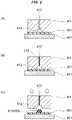
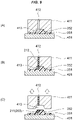
FIGS. 2 (A) through 2 (C) are vertical cross-sectional views temporally showing each step executed upon shaping a sticking agent as a first embodiment. -
FIGS. 3 (A) through 3 (D) are vertical cross-sectional views temporally showing each step executed upon transferring a sticking agent to a separator as the first embodiment. -
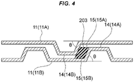
FIG. 4 is a vertical cross-sectional view showing a seal structure of sealing a gap between a pair of separators. -
FIGS. 5 (A) through 5 (C) are vertical cross-sectional views temporally showing each step executed upon shaping a sticking agent as a second embodiment. -
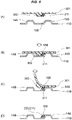
FIGS. 6 (A) through 6 (D) are vertical cross-sectional views temporally showing each step executed upon transferring a sticking agent to a separator as the second embodiment. -
FIGS. 7 (A) through 7 (D) are vertical cross-sectional views temporally showing each step executed upon shaping a sticking agent as a third embodiment. -
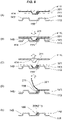
FIGS. 8 (A) through 8 (E) are vertical cross-sectional views temporally showing each step executed upon transferring a sticking agent to a separator as the third embodiment. -
FIGS. 9 (A) through 9 (C) are vertical cross-sectional views temporally showing each step executed upon shaping a sticking agent as a fourth embodiment. -
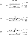
FIGS. 10 (A) through 10 (C) are vertical cross-sectional views temporally showing each step executed upon transfer in a first stage of a sticking agent to a separator as the fourth embodiment. -
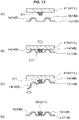
FIGS. 11 (A) through 11 (C) are vertical cross-sectional views temporally showing each step executed upon transfer in a second stage of a sticking agent to a separator as the fourth embodiment. -
FIGS. 12 (A) through 12 (C) are vertical cross-sectional views temporally showing each step executed upon shaping a sticking agent as a fifth embodiment. -
FIGS. 13 (A) through 13 (D) are vertical cross-sectional views temporally showing each step executed upon transferring a sticking agent to a separator as the fifth embodiment. -
FIGS. 14 (A) through 14 (C) are vertical cross-sectional views temporally showing each step executed upon shaping a sticking agent as a sixth embodiment. -
FIGS. 15 (A) through 15 (D) are vertical cross-sectional views temporally showing each step executed upon transferring a sticking agent to a separator as the sixth embodiment. - A method for manufacturing a fuel battery separator gasket according to the present embodiment is a method of shaping a gasket to be provided on a separator used in a fuel cell and transferring the gasket to the separator. An example of a fuel cell to which the method of the present embodiment is applied will first be described.
- As shown in
FIG. 1 , a fuel cell 1 has a stacked structure in which a plurality offuel battery cells 2 are stacked. In thefuel battery cell 2, anelectrolyte membrane 102 provided with amembrane electrode assembly 101 called a MEA (Membrane Electrode Assembly) is interposed between a pair ofseparators 11 for the fuel cell. Suchfuel battery cells 2 are stacked through acooling surface seal 201. InFIG. 1 , only two sets offuel battery cells 2 are drawn, but in reality, hundreds of sets offuel battery cells 2 are stacked to constitute the fuel cell 1. - The
membrane electrode assembly 101 is a structure in which electrodes not shown in the drawing are provided at the central portions of both surfaces of theelectrolyte membrane 102. The electrode has a stacked structure having a catalyst layer formed on theelectrolyte membrane 102 and a gas diffusion layer (GDL) formed on the catalyst layer (neither is shown). In such an electrode, one surface of theelectrolyte membrane 102 is used as an anode electrode, and the surface opposite thereto is used as a cathode electrode. - The
separator 11 for the fuel cell is a flat plate-shaped member formed of a resin such as carbon as an example. However, the separator is not limited to the brittle member like such a carbon-made one. As another example, a flat plate-like member that can be pressed, such as a thin stainless steel plate, may be used as theseparator 11. - The
separator 11 has a rectangular planar shape and is provided with anarrangement region 12 for arranging themembrane electrode assembly 101. Openings provided three by three at positions of both ends out of thearrangement region 12 are manifolds 13 for circulating fluid used for power generation or generated by power generation. The fluid caused to flow through themanifolds 13 is a fuel gas (hydrogen), an oxidizing gas (oxygen), water generated by electrochemical reaction during power generation, an excess oxidizing gas, a refrigerant, or the like. - The
manifolds 103 are provided even on theelectrolyte membrane 102 in alignment with themanifolds 13 provided on theseparator 11. Thesemanifolds 103 are openings which are respectively provided three at positions of both ends away from themembrane electrode assembly 101. - The fuel cell 1 uses the
manifolds electrolyte membrane 102 provided with themembrane electrode assembly 101 and theseparator 11A facing one surface of theelectrolyte membrane 102, and to introduce the oxidizing gas (oxygen) between theelectrolyte membrane 102 and theseparator 11B facing the surface opposite to one surface of theelectrolyte membrane 102. Cooling water used as the refrigerant is introduced between the two sets offuel battery cells 2 sealed by thecooling surface seal 201. At this time, the fuel gas, the oxidizing gas, and the cooling water flow through respective flow paths formed by the pair of separators 11 (11A, 11B) that assemble thefuel battery cell 2. - The pair of
separators 11 face each other with theelectrolyte membrane 102 as a mating member interposed therebetween to form thefuel battery cells 2. Theseparator 11 includes abead 14 that forms a fluid flow path between the separator and theelectrolyte membrane 102 in close contact with theelectrolyte membrane 102. A space between theelectrolyte membrane 102 and thebead 14A of theseparator 11A forms a flow path for the fuel gas. A space between theelectrolyte membrane 102 and thebead 14B of theseparator 11B forms a flow path for the oxidizing gas. A space between thebeads separator 11A of one set offuel battery cells 2 and theseparator 11B of the set offuel battery cells 2 overlapping theseparator 11A forms a flow path for the cooling water. - The
fuel battery cell 2 has a seal structure at the outer peripheral edges of theseparator 11 and themembrane electrode assembly 101, and at the peripheral edges of themanifolds surface seal 201 interposed between the two sets offuel battery cells 2 and areaction surface seal 202 provided between theseparator 11 and themembrane electrode assembly 101. In such a seal structure, the flow path for the fuel gas and the surplus fuel gas, the flow path for the oxidizing gas and the water generated by the electrochemical reaction at the power generation, and the flow path for the cooling water as the refrigerant are made independent of each other to prevent mixing of different types of fluids. - A
gasket 203 fixed to theseparator 11 is used for the coolingsurface seal 201 and thereaction surface seal 202 which form the seal structure. Hereinafter, embodiments of a method for manufacturing a gasket for a fuel cell separator will be described. - A first embodiment will be described based on
FIGS. 2 (A) through 2 (C) andFIGS. 3 (A) through 3 (D) . The gasket manufacturing method of the present embodiment includes a shaping step and a transfer step. - The shaping step is a step of shaping a
sticking agent 211 to be agasket 203 on aflexible substrate 301 having flexibility, for example, a resin film. - As shown in
FIG. 2 (A) , theflexible substrate 301 is placed on abase 401, and a shapingmold 411 is placed thereon via theflexible substrate 301. The shapingmold 411 is provided with agate 412 and acavity 413. Thecavity 413 has a shape for forming thegasket 203. - As shown in
FIG. 2 (B) , amaterial 212 of the stickingagent 211, for example, unvulcanized butyl rubber or the like, which is a rubber-like elastic material, is guided from thegate 412 to thecavity 413. As a molding method at this time, injection molding or transfer molding is adopted. - As shown in
FIG. 2 (C) , the stickingagent 211 is shaped on the flat surface of theflexible substrate 301 by separating the shapingmold 411 from thebase 401. The shaped stickingagent 211 becomes thegasket 203. - In order to allow the
sticking agent 211 to be shaped on theflexible substrate 301 by separating the shapingmold 411 from thebase 401, theflexible substrate 301 is configured to exhibit stronger stickiness than a wall portion of thecavity 413. - As the sticking
agent 211 used in the shaping step, e.g., a rubber-based sticking agent using, as base polymer, butyl rubber, polyisobutylene rubber, styrene-butadiene rubber, ethylenepropylene diene rubber, natural rubber, or the like can be used. - It is also possible to blend the
sticking agent 211 with additives. The additives that can be blended include, for example, cross-linking agents, tackifiers, fillers, anti-aging agents, and the like. - The transfer step is a step of transferring the sticking
agent 211 shaped on theflexible substrate 301 to theseparator 11 to shape thegasket 203. - As shown in
FIG. 3 (A) , the stickingagent 211 shaped on theflexible substrate 301 is faced with one of theseparators 11, for example, theseparator 11B on the side in contact with the oxidizing gas (oxygen). The position where they face each other is a fixed position of thegasket 203 with respect to theseparator 11B. In the present embodiment, a region other than thebead 14B provided on theseparator 11B is set as the fixed position. - As a modification of the present embodiment, the top of the
bead 14B provided on theseparator 11B may be set as a fixed position. - As shown in
FIG. 3 (B) , theseparator 11B and theflexible substrate 301 are brought close to each other, and the stickingagent 211 is brought into contact with the position where thegasket 203 should be fixed. The stickingagent 211 sticks to theseparator 11B due to its own stickiness. - As shown in
FIG. 3 (C) , theflexible substrate 301 is bent and peeled from the stickingagent 211. At this time, theseparator 11B is configured to exhibit stronger stickiness than theflexible substrate 301. Therefore, the stickingagent 211 maintains a state of remaining stuck to theflexible substrate 301, and theflexible substrate 301 is peeled off from the stickingagent 211. - As shown in
FIG. 3 (D) , as a result, the stickingagent 211 is fixed to theseparator 11B, and the stickingagent 211 becomes thegasket 203. - The sticking
agent 211 serving as thegasket 203 may or may not be cross-linked. The cross-linking of the stickingagent 211 is carried out after shaping on theflexible substrate 301 or after transferring to theseparator 11B. - The
gasket 203 can be formed on theseparator 11B in this manner. At this time, theseparator 11B is not subjected to the pressure at the time of gasket molding, for example, the pressure due to mold pressing or injection pressure, etc., and thegasket 203 can be shaped on theseparator 11B without causing breakage or damage. Accordingly, it is possible to use as the separator 11 (11A, 11B), a brittle material such as one made of carbon. - A second embodiment will be described based on
FIG. 4 andFIGS. 6 (A) through 6 (D) . The same parts as those in the first embodiment are designated by the same reference numerals, and a description thereof will also be omitted. -
FIG. 4 shows a seal structure of the coolingsurface seal 201 and thereaction surface seal 202, which are the premise of a gasket manufacturing method of the present embodiment. In this seal structure, thebeads 14 of theseparators 11 are overlapped with each other in a nested manner. As an example, thebead 14B of theseparator 11B facing the surface opposite to one surface of theelectrolyte membrane 102 is formed larger than thebead 14A of theseparator 11A facing one surface of theelectrolyte membrane 102 provided with themembrane electrode assembly 101. Thebead 14B has entered thebead 14A in a non-contact state. - The beads 14 (14A, 14B) of the pair of
separators 11 respectively have a rising angle θ from theseparator 11, which is set to, for example, about 70°. Therefore, side walls 15 (15A, 15B) of the beads 14 (14A, 14B) facing each other, of the pair ofseparators 11 are inclined with respect to theseparators 11. - The
gasket 203 used in such a seal structure is arranged between the side walls 15 (15A, 15B) of the beads 14 (14A, 14B) facing each other by overlapping in the nested manner. Since the rising angle θ of thebead 14 from theseparator 11 is about 70 °, thegasket 203 has a parallelogram cross-sectional shape. - Similar to the first embodiment, since the
gasket 203 is formed by the stickingagent 211, it is stuck and fixed to the side walls 15 (15A, 15B) of the beads 14 (14A, 14B) facing each other, of the pair ofseparators 11. Further, thegasket 203 is stuck and fixed not only to theside wall 15 of thebead 14 but also to the surface of theseparator 11 which communicates with theside wall 15. - The gasket manufacturing method of the present embodiment produces the
gasket 203 which conforms to the seal structure of the coolingsurface seal 201 and thereaction surface seal 202 as described above. The present manufacturing method includes a shaping step and a transfer step as in the first embodiment. - The shaping step is a step of shaping the sticking
agent 211 to be thegasket 203 on theflexible substrate 301 having flexibility, for example, a resin film. - As shown in
FIG. 5 (A) , theflexible substrate 301 is placed on thebase 401, and the shapingmold 411 is placed thereon via theflexible substrate 301. The shapingmold 411 is provided with thegate 412 and thecavity 413. - The
flexible substrate 301 includes aprotrusion 302 which enters between the twoadjacent beads 14B provided on one of the pair ofseparators 11, for example, theseparator 11B on the side in contact with the oxidizing gas (oxygen). Similar to thebead 14B, theprotrusion 302 rises from theflexible substrate 301 at a rising angle of about 70°. That is, theprotrusion 302 is formed in a shape imitating theside wall 15B of thebead 14B to which thesticking agent 211 serving as thegasket 203 is stuck. - The
cavity 413 provided in the shapingmold 411 has a shape for forming thegasket 203 at the portion where theprotrusion 302 of theflexible substrate 301 is arranged and in communication with thegate 412. - As shown in
FIG. 5 (B) , thematerial 212 of the stickingagent 211, for example, unvulcanized butyl rubber or the like, which is a rubber-like elastic material, is guided from thegate 412 to thecavity 413. As the molding method at this time, injection molding or transfer molding is adopted. - As shown in
FIG. 5 (C) , by separating the shapingmold 411 from thebase 401, the stickingagent 211 is shaped on theflexible substrate 301 along theprotrusion 302. The shaped stickingagent 211 becomes thegasket 203. - In order to allow the
sticking agent 211 to be shaped on theflexible substrate 301 by separating the shapingmold 411 from thebase 401, theflexible substrate 301 is configured to exhibit stronger stickiness than the wall portion of thecavity 413. - The transfer step is a step of transferring the sticking
agent 211 shaped on theflexible substrate 301 to theseparator 11 to form thegasket 203. - As shown in
FIG. 6 (A) , the stickingagent 211 shaped on theflexible substrate 301 is made to face theseparator 11B on the side in contact with the oxidizing gas (oxygen). The position where they face each other is a fixed position of thegasket 203 with respect to theseparator 11B. As shown inFIG. 4 , the fixed position of thegasket 203 is theside wall 15B of thebead 14B which is nestedly overlapped with thebead 14A of theseparator 11A on the side in contact with the fuel gas (hydrogen). - As shown in
FIG. 6 (B) , theseparator 11B and theflexible substrate 301 are brought close to each other, and the stickingagent 211 is brought into contact with the position where thegasket 203 should be fixed. The stickingagent 211 is stuck to theseparator 11B due to its own stickiness. - As shown in
FIG. 6 (C) , theflexible substrate 301 is bent and peeled from the stickingagent 211. At this time, theseparator 11B is configured to exhibit stronger stickiness than theflexible substrate 301. Therefore, the stickingagent 211 maintains a state of remaining stuck to theseparator 11B, and theflexible substrate 301 is peeled off from the stickingagent 211. - As shown in
FIG. 6 (D) , as a result, the stickingagent 211 is fixed to theseparator 11B, and the stickingagent 211 becomes thegasket 203. - The
gasket 203 can be formed on theseparator 11B in this manner. Theseparator 11B is not subjected to the pressure at the time of gasket molding, for example, the pressure due to mold pressing or injection pressure, etc., and thegasket 203 can be shaped on theseparator 11B without causing breakage or damage. Accordingly, it is possible to use as the separator 11 (11A, 11B), a brittle material such as one made of carbon. - A third embodiment will be described based on
FIGS. 7 (A) through 7 (D) andFIG. 8 (A) through 8 (E) . The same parts as those in the second embodiment are designated by the same reference numerals, and a description thereof will also be omitted. - The present embodiment is an example in which the
protrusion 302 is formed by embossing thematerial 212 of the stickingagent 211 against the shapingmold 411 by filling pressure, instead of using theflexible substrate 301 provided with theprotrusion 302 in advance. In such a manufacturing method, a more flexible film-like material is used as theflexible substrate 301. - As with the method according to the second embodiment, the gasket manufacturing method of the present embodiment also produces the
gasket 203 that conforms to the seal structure of the coolingsurface seal 201 and thereaction surface seal 202 such as shown inFIG. 4 . The gasket manufacturing method is similar to the gasket manufacturing methods of the first and second embodiments even in that it includes the shaping step and the transfer step. - The shaping step is a step of shaping the sticking
agent 211 to be thegasket 203 on theflexible substrate 301 having flexibility such as a resin film. In the present embodiment, alower mold 411L and anupper mold 411U are used. - As shown in
FIG. 7 (A) , theflexible substrate 301 is placed on thelower mold 411L, and theupper mold 411U is placed via theflexible substrate 301. Thelower mold 411L is provided with aprotrusion 414, and theupper mold 411U is provided with agate 412 and acavity 413. - The
protrusion 414 provided on thelower mold 411L corresponds to theprotrusion 302 provided on theflexible substrate 301 of the second embodiment, and rises at a rising angle of about 70° from theflexible substrate 301 similar to thebead 14B. That is, theprotrusion 302 is formed in a shape imitating theside wall 15B of thebead 14B to which thesticking agent 211 serving as thegasket 203 is stuck. - The
cavity 413 provided in theupper mold 411U has a shape for arranging theprotrusion 414 of thelower mold 411L and forming thegasket 203 in the portion communicating with thegate 412. - As shown in
FIG. 7 (B) , thematerial 212 of the stickingagent 211, for example, unvulcanized butyl rubber or the like, which is a rubber-like elastic material, is guided from thegate 412 to thecavity 413. - As shown in
FIG. 7 (C) , theflexible substrate 301 bends into the shape of theprotrusion 414 by the filling pressure of thematerial 212 of the stickingagent 211 into thecavity 413. - As shown in
FIG. 7 (D) , by separating theupper mold 411U from thelower mold 411L, the stickingagent 211 is shaped on theflexible substrate 301 along theprotrusion 414. The shaped stickingagent 211 becomes thegasket 203. - In order to allow the
sticking agent 211 to be shaped on theflexible substrate 301 by separating theupper mold 411U from thelower mold 411L, theflexible substrate 301 is configured to exhibit stronger stickiness than the wall portion of thecavity 413. - The transfer step is a step of transferring the sticking
agent 211 shaped on theflexible substrate 301 to theseparator 11 to form thegasket 203. - As shown in
FIG. 8 (A) , the stickingagent 211 shaped on theflexible substrate 301 for eachlower mold 411L is made to face theseparator 11B on the side in contact with the oxidizing gas (oxygen). The position where they face each other is a fixed position of thegasket 203 with respect to theseparator 11B. As shown inFIG. 4 , the fixing position of thegasket 203 is theside wall 15B of thebead 14B which is nestedly overlapped with thebead 14A of theseparator 11A on the side in contact with the fuel gas (hydrogen). - As shown in
FIG. 8 (B) , theseparator 11B attached to thelower mold 411L and theflexible substrate 301 are brought close to each other, and the stickingagent 211 is brought into contact with the position where thegasket 203 should be fixed. The stickingagent 211 is stuck to theseparator 11B due to its own stickiness. - As shown in
FIG. 8 (C) , thelower mold 411L is removed from theflexible substrate 301. At this time, the bonding force between theflexible substrate 301 and thelower mold 411L is smaller than the sticking force between theseparator 11B and the stickingagent 211 and the sticking force between the stickingagent 211 and theflexible substrate 301. Therefore, thelower mold 411L is smoothly removed from theflexible substrate 301. - As shown in
FIG. 8 (D) , theflexible substrate 301 is bent and peeled from the stickingagent 211. At this time, theseparator 11B is configured to exhibit stronger stickiness than theflexible substrate 301. Therefore, the stickingagent 211 maintains a state of remaining stuck to theflexible substrate 301, and theflexible substrate 301 is peeled off from the stickingagent 211. - As shown in
FIG. 8 (E) , as a result, the stickingagent 211 is fixed to theseparator 11B, and the stickingagent 211 becomes thegasket 203. - In this way, the
gasket 203 can be formed on theseparator 11B. At this time, theseparator 11B is not subjected to the pressure at the time of gasket molding, for example, the pressure due to the mold pressing or the injection pressure or the like, and thegasket 203 can be shaped on theseparator 11B without causing breakage or damage. Thus, as the separator 11 (11A, 11B), a brittle material such as one made of carbon can be used. - A fourth embodiment will be described with reference to
FIGS. 9 (A) through 9 (C) andFIGS. 11 (A) through 11 (C) . The same parts as those of the second embodiment are indicated by the same reference numerals, and a description thereof will also be omitted. - In the present embodiment, the sticking
agent 211 is not directly shaped on theflexible substrate 301, but is shaped on anintermediate substrate 351 and transferred from theintermediate substrate 351 to theflexible substrate 301, and further transferred from theflexible substrate 301 to theseparator 11. - In a manner similar to the method of the second embodiment, the gasket manufacturing method of the present embodiment also produces a
gasket 203 that conforms to the seal structure of the coolingsurface seal 201 and thereaction surface seal 202 such as shown inFIG. 4 . The gasket manufacturing method is similar to the gasket manufacturing methods of the first and second embodiments even in that it includes the shaping step and the transfer step. However, as described above, it is provided with a two-step transfer step of theintermediate substrate 351 to the flexible substrate 301 (intermediate transfer step) and theflexible substrate 301 to the separator 11 (final transfer step). - The shaping step is a step of shaping the sticking
agent 211 to be thegasket 203 on theintermediate substrate 351. Theintermediate substrate 351 does not have to have flexibility and may be a member made of a hard material. - As shown in
FIG. 9 (A) , theintermediate substrate 351 is placed on thebase 401, and the shapingmold 411 is placed via theintermediate substrate 351. The shapingmold 411 is provided with agate 412 and acavity 413. - The
intermediate substrate 351 includes aprotrusion 352 that enters between twoadjacent beads 14B provided on one of the pair ofseparators 11, for example, theseparator 11B on the side in contact with the oxidizing gas (oxygen). Similar to thebead 14B, theprotrusion 352 rises from theflexible substrate 301 at a rising angle of about 70°. That is, theprotrusion 352 is formed in a shape imitating theside wall 15B of thebead 14B to which thesticking agent 211 serving as thegasket 203 is stuck. - The
cavity 413 provided in the shapingmold 411 has a shape for arranging theprotrusion 352 provided in theintermediate substrate 351 and shaping thegasket 203 in a portion which communicates with thegate 412. - As shown in
FIG. 9 (B) , thematerial 212 of the stickingagent 211, for example, unvulcanized butyl rubber or the like, which is a rubber-like elastic material, is guided from thegate 412 to thecavity 413. As the molding method at this time, injection molding or transfer molding is adopted. - As shown in
FIG. 9 (C) , by separating the shapingmold 411 from thebase 401, the stickingagent 211 is shaped on theintermediate substrate 351 along theprotrusion 352. The shaped stickingagent 211 becomes thegasket 203. - In order to allow the
sticking agent 211 to be shaped on theintermediate substrate 351 by separating the shapingmold 411 from thebase 401, theintermediate substrate 351 is configured to exhibit stronger stickiness than the wall portion of thecavity 413. - The intermediate transfer step is a step of transferring the sticking
agent 211 shaped on theintermediate substrate 351 to theflexible substrate 301. Theflexible substrate 301 has a flat shape which is not the shape provided with theprotrusion 302 as in the second embodiment. - As shown in
FIG. 10 (A) , the stickingagent 211 shaped on theintermediate substrate 351 is made to face theflexible substrate 301. - As shown in
FIG. 10 (B) , theflexible substrate 301 and theintermediate substrate 351 are brought close to each other, and the stickingagent 211 is brought into contact with theflexible substrate 301. The stickingagent 211 sticks to theflexible substrate 301 due to its own stickiness. - As shown in
FIG. 10 (C) , theflexible substrate 301 is separated from theintermediate substrate 351. At this time, theflexible substrate 301 is configured to exhibit stronger stickiness than theintermediate substrate 351. Therefore, the stickingagent 211 maintains a state of remaining stuck to theflexible substrate 301, and theflexible substrate 301 is peeled off from the stickingagent 211. - The final transfer step is a step of transferring the sticking
agent 211 shaped on theflexible substrate 301 to theseparator 11 to form thegasket 203. - As shown in
FIG. 11 (A) , the stickingagent 211 shaped on theflexible substrate 301 is made to face theseparator 11B on the side in contact with the oxidizing gas (oxygen). The position to face them each other is a fixed position of thegasket 203 with respect to theseparator 11B. As shown inFIG. 4 , the fixed position of thegasket 203 is theside wall 15B of thebead 14B which is nestedly overlapped with thebead 14A of theseparator 11A on the side in contact with the fuel gas (hydrogen). - As shown in
FIG. 11 (B) , theseparator 11B and theflexible substrate 301 are brought close to each other, and the stickingagent 211 is brought into contact with the position where thegasket 203 should be fixed. The stickingagent 211 sticks to theseparator 11B due to its own stickiness. - As shown in
FIG. 11 (C) , theflexible substrate 301 is bent and peeled off from the stickingagent 211. At this time, theseparator 11B is configured to exhibit stronger stickiness than theflexible substrate 301. Therefore, the stickingagent 211 maintains a state of remaining stuck to theflexible substrate 301, and theflexible substrate 301 is peeled off from the stickingagent 211. - As shown in
FIG. 11 (D) , as a result, the stickingagent 211 is fixed to theseparator 11B, and the stickingagent 211 becomes thegasket 203. - The sticking
agent 211 to be thegasket 203 may or may not be cross-linked as in the first to third embodiments. The cross-linking of the stickingagent 211 is carried out after shaping on theintermediate substrate 351 and then transferring to theflexible substrate 301 or after transferring to theseparator 11B. - The
gasket 203 can be formed on theseparator 11B in this manner. At this time, theseparator 11B is not subjected to the pressure at the time of gasket molding, for example, the pressure due to the mold pressing or the injection pressure, etc., and thegasket 203 can be shaped on theseparator 11B without causing breakage or damage. Accordingly, as the separator 11 (11A, 11B), a brittle material such as one made of carbon can be used. - As a modification of the present embodiment, a region other than the
bead 14B of theseparator 11B or the top of thebead 14B provided on theseparator 11B may be set as a fixed position of thegasket 203 with respect to theseparator 11B. When these modifications are adopted, the stickingagent 211 is shaped on the flat surface of theintermediate substrate 351 in the shaping step, and the stickingagent 211 is intermediate-transferred onto the flat surface of theflexible substrate 301 in the intermediate transfer step. - Thus, in the final transfer step, the sticking
agent 211 can be transferred from theflexible substrate 301 to the region other than thebead 14B of theseparator 11B or the top of thebead 14B provided on theseparator 11B. - A fifth embodiment will be described with reference to
FIGS. 12 (A) through 12 (C) andFIGS. 13 (A) through 13 (D) . The same parts as those in the first embodiment are indicated by the same reference numerals, and a description thereof will also be omitted. - The shaping
mold 411 of the present embodiment includes anupper mold 411U and alower mold 411L. The shaping step is a step of shaping the stickingagent 211 to be thegasket 203 into thelower mold 411L. - As shown in
FIG. 12 (A) , thelower mold 411L of the shapingmold 411 is placed on thebase 401. Theupper mold 411U of the shapingmold 411 is provided with agate 412 and acavity 413. Thecavity 413 has a shape for forming thegasket 203. - As shown in
FIG. 12 (B) , thematerial 212 of the stickingagent 211, for example, unvulcanized butyl rubber or the like, which is a rubber-like elastic material, is guided from thegate 412 to thecavity 413. As the molding method at this time, injection molding or transfer molding is adopted. - As shown in
FIG. 12 (C) , by separating the shapingmold 411 from thebase 401, the stickingagent 211 is shaped on the flat surface of thelower mold 411L. The shaped stickingagent 211 becomes thegasket 203. - In order to separate the shaping
mold 411 from the base 401 so that the stickingagent 211 can be shaped on thelower mold 411L, thelower mold 411L is configured to exhibit stronger stickiness than the wall portion of thecavity 413. - The transfer step is a step of transferring the sticking
agent 211 shaped on thelower mold 411L to theseparator 11 to form thegasket 203. - As shown in
FIG. 13 (A) , the stickingagent 211 shaped on thelower mold 411L is faced with one of theseparators 11, for example, theseparator 11B on the side in contact with the oxidizing gas (oxygen). The position to face them each other is a fixed position of thegasket 203 with respect to theseparator 11B. In the present embodiment, a region other than thebead 14B provided on theseparator 11B is set as the fixed position. - As shown in
FIG. 13 (B) , theseparator 11B and thelower mold 411L are brought close to each other, and the stickingagent 211 is brought into contact with the position where thegasket 203 should be fixed. The stickingagent 211 sticks to theseparator 11B due to its own stickiness. - As shown in
FIG. 13 (C) , theseparator 11B is bent to peel off the stickingagent 211 from thelower mold 411L. At this time, theseparator 11B is configured to exhibit stronger stickiness than thelower mold 411L. Therefore, the stickingagent 211 maintains a state of remaining stuck to theseparator 11B and is peeled off from thelower mold 411L. - As shown in
FIG. 13 (D) , as a result, the stickingagent 211 is fixed to theseparator 11B, and the stickingagent 211 becomes thegasket 203. - The sticking
agent 211 to server as thegasket 203 may or may not be cross-linked as in the first to fourth embodiments. The cross-linking of the stickingagent 211 is carried out after shaping on thelower mold 411L or after transferring to theseparator 11B. - The
gasket 203 can be formed on theseparator 11B in this manner. At this time, theseparator 11B is not subjected to the pressure at the time of gasket molding, for example, the pressure due to the mold pressing or the injection pressure, or the like, and thegasket 203 can be shaped on theseparator 11B without causing breakage or damage. Thus, as the separator 11 (11A, 11B), a brittle material such as one made of carbon can be used. - A sixth embodiment will be described with reference to
FIGS. 14 (A) through 14 (C) andFIGS. 15 (A) through 15 (D) . The same parts as those in the fifth embodiment are indicated by the same reference numerals, and the description thereof will also be omitted. - The gasket manufacturing method of the present embodiment produces a
gasket 203 that conforms to the seal structure of the coolingsurface seal 201 and thereaction surface seal 202 as shown inFIG. 4 in a manner similar to the method of the second embodiment. Similar to the gasket manufacturing method of the fifth embodiment, the method of the present embodiment also includes a shaping step and a transfer step. - The shaping step is a step of shaping the sticking
agent 211 to be thegasket 203 on thelower mold 411L. - As shown in
FIG. 14 (A) , thelower mold 411L of the shapingmold 411 is placed on thebase 401. Theupper mold 411U of the shapingmold 411 is provided with agate 412 and acavity 413. - The
lower mold 411L is provided with aprotrusion 414 that enters between twoadjacent beads 14B provided on one of the pair ofseparators 11, for example, theseparator 11B on the side in contact with the oxidizing gas (oxygen). As with thebead 14B, theprotrusion 414 rises from thelower mold 411L at a rising angle of about 70°. That is, theprotrusion 414 is formed in a shape imitating theside wall 15B of thebead 14B to which thesticking agent 211 serving as thegasket 203 sticks. - The
cavity 413 provided in theupper mold 411U has a shape for arranging theprotrusion 414 of thelower mold 411L and shaping thegasket 203 in a portion communicating with thegate 412. - As shown in
FIG. 14 (B) , thematerial 212 of the stickingagent 211, for example, unvulcanized butyl rubber, which is a rubber-like elastic material, is guided from thegate 412 to thecavity 413. As the molding method at this time, injection molding or transfer molding is adopted. - As shown in
FIG. 14 (C) , by separating the shapingmold 411 from thebase 401, the stickingagent 211 is shaped on thelower mold 411L along theprotrusion 414. The shaped stickingagent 211 becomes thegasket 203. - In order to separate the shaping
mold 411 from the base 401 so that the stickingagent 211 can be shaped on thelower mold 411L, thelower mold 411L is configured to exhibit stronger stickiness than the wall portion of thecavity 413. - The transfer step is a step of transferring the sticking
agent 211 shaped on thelower mold 411L to theseparator 11 to shape thegasket 203. - As shown in
FIG. 15 (A) , the stickingagent 211 shaped on thelower mold 411L is faced with one of theseparators 11, for example, theseparator 11B on the side in contact with the oxidizing gas (oxygen). The position to face them each other is a fixed position of thegasket 203 with respect to theseparator 11B. As shown inFIG. 4 , the fixed position of thegasket 203 is theside wall 15B of thebead 14B which is nestedly overlapped with thebead 14A of theseparator 11A on the side in contact with the fuel gas (hydrogen). - As shown in
FIG. 15 (B) , theseparator 11B and thelower mold 411L are brought close to each other, and the stickingagent 211 is brought into contact with the position where thegasket 203 should be fixed. The stickingagent 211 sticks to theseparator 11B due to its own stickiness. - As shown in
FIG. 15 (C) , theseparator 11B is bent to peel off the stickingagent 211 from thelower mold 411L. At this time, theseparator 11B is configured to exhibit stronger stickiness than thelower mold 411L. Therefore, the stickingagent 211 maintains a state of remaining stuck to theseparator 11B and is peeled off from thelower mold 411L. - As shown in
FIG. 15 (D) , as a result, the stickingagent 211 is fixed to theseparator 11B, and the stickingagent 211 becomes thegasket 203. - The
gasket 203 can be shaped on theseparator 11B in this manner. At this time, theseparator 11B is not subjected to the pressure at the time of gasket molding, for example, the pressure due to the mold pressing or the injection pressure, etc., and thegasket 203 can be shaped on theseparator 11B without causing breakage or damage. Thus, as the separator 11 (11A, 11B), a brittle material such as one made of carbon can be used. -
- 1
- fuel cell
- 2
- fuel battery cell
- 11, 11A, 11B
- separator
- 12
- arrangement region
- 13
- manifold
- 14, 14A, 14B
- bead
- 15, 15A, 15B
- side wall
- 101
- membrane electrode assembly
- 102
- electrolyte membrane (mating member)
- 103
- manifold
- 201
- cooling surface seal
- 202
- reaction surface seal
- 203
- gasket
- 211
- sticking agent
- 212
- material
- 301
- flexible substrate
- 302
- protrusion
- 351
- intermediate substrate
- 352
- protrusion
- 401
- base
- 411
- shaping mold
- 411U
- upper mold
- 411L
- lower mold
- 412
- cavity
- 413
- gate
- 414
- protrusion
Claims (10)
- A method for manufacturing a fuel battery separator gasket, comprising the steps of:shaping a sticking agent to be a gasket on a flexible substrate having flexibility by using a shaping mold; andtransferring the sticking agent shaped on the flexible substrate to one of a pair of separators facing each other with a mating member interposed therebetween and each having a bead forming a flow path of fluid between the bead and the mating member in close contact with the mating member to shape the gasket.
- The method for manufacturing the fuel battery separator gasket according to claim 1, wherein a transfer position of the sticking agent is a side surface of the bead.
- The method for manufacturing the fuel battery separator gasket according to claim 2, wherein a shaping position of the sticking agent is a side wall of a protrusion provided on the flexible substrate, which enters between the two adjacent beads.
- The method for manufacturing the fuel battery separator gasket according to claim 3, wherein the protrusion of the flexible substrate is shaped by embossing the sticking agent against the shaping mold by filling pressure thereof.
- A method for manufacturing a fuel battery separator gasket, comprising the steps of:shaping a sticking agent to be a gasket on an intermediate substrate by using a shaping mold;transferring the sticking agent shaped on the intermediate substrate to a flexible substrate having flexibility; andtransferring the sticking agent transferred to the flexible substrate to one of a pair of separators facing each other with a mating member interposed therebetween and each having a bead forming a flow path of fluid between the bead and the mating member in close contact with the mating member to shape the gasket.
- The method for manufacturing the fuel battery separator gasket according to claim 5, wherein a transfer position of the sticking agent is a side surface of the bead.
- The method for manufacturing the fuel battery separator gasket according to claim 6, wherein a shaping position of the sticking agent is a side surface of a protrusion provided in the intermediate substrate.
- A method for manufacturing a fuel battery separator gasket, comprising the steps of:shaping a sticking agent to be a gasket on a lower mold of a shaping mold having an upper mold and the lower mold; andtransferring the sticking agent shaped on the lower mold to one of a pair of separators facing each other with a mating member interposed therebetween and each having a bead forming a flow path of fluid between the bead and the mating member in close contact with the mating member to shape the gasket.
- The method for manufacturing the fuel battery separator gasket according to claim 8, wherein a transfer position of the sticking agent is a side surface of the bead.
- The method for manufacturing the fuel battery separator gasket according to claim 9, wherein a shaping position of the sticking agent is a side surface of a protrusion provided on the lower mold which enters between the two adjacent beads.
Applications Claiming Priority (2)
| Application Number | Priority Date | Filing Date | Title |
|---|---|---|---|
| JP2019169232 | 2019-09-18 | ||
| PCT/JP2020/033026 WO2021054113A1 (en) | 2019-09-18 | 2020-09-01 | Method for manufacturing fuel battery cell separator gasket |
Publications (2)
| Publication Number | Publication Date |
|---|---|
| EP4033574A1 true EP4033574A1 (en) | 2022-07-27 |
| EP4033574A4 EP4033574A4 (en) | 2024-11-06 |
Family
ID=74884249
Family Applications (1)
| Application Number | Title | Priority Date | Filing Date |
|---|---|---|---|
| EP20865088.7A Pending EP4033574A4 (en) | 2019-09-18 | 2020-09-01 | METHOD FOR PRODUCING A FUEL CELL SEPARATION GASKET |
Country Status (5)
| Country | Link |
|---|---|
| US (1) | US11973246B2 (en) |
| EP (1) | EP4033574A4 (en) |
| JP (1) | JP7385668B2 (en) |
| CN (1) | CN113767490A (en) |
| WO (1) | WO2021054113A1 (en) |
Family Cites Families (15)
| Publication number | Priority date | Publication date | Assignee | Title |
|---|---|---|---|---|
| JP4420166B2 (en) * | 2001-03-02 | 2010-02-24 | Nok株式会社 | Manufacturing method of fuel cell component |
| JP2007149472A (en) * | 2005-11-28 | 2007-06-14 | Uchiyama Mfg Corp | Gasket molding method of constituent member for fuel cell |
| JP4367477B2 (en) * | 2006-10-30 | 2009-11-18 | トヨタ自動車株式会社 | Fuel cell |
| JP5099352B2 (en) * | 2008-05-23 | 2012-12-19 | Nok株式会社 | Manufacturing method of seal parts |
| KR101141366B1 (en) * | 2009-10-27 | 2012-05-03 | 현대하이스코 주식회사 | Solid gasket fabrication method for fuel cell separator |
| JP6098948B2 (en) * | 2014-11-06 | 2017-03-22 | トヨタ自動車株式会社 | Fuel cell separator, fuel cell and fuel cell |
| JP6487701B2 (en) | 2015-01-30 | 2019-03-20 | Nok株式会社 | Gasket for fuel cell |
| JP6495106B2 (en) | 2015-06-04 | 2019-04-03 | Nok株式会社 | Gasket and manufacturing method thereof |
| JP6600230B2 (en) * | 2015-06-29 | 2019-10-30 | Nok株式会社 | Manufacturing method of gasket |
| JP6641812B2 (en) * | 2015-09-10 | 2020-02-05 | 凸版印刷株式会社 | Manufacturing method of membrane electrode assembly |
| JP6673678B2 (en) * | 2015-12-03 | 2020-03-25 | Nok株式会社 | Gasket with carrier film and method of manufacturing the same |
| WO2017188059A1 (en) * | 2016-04-28 | 2017-11-02 | Nok株式会社 | Liquid silicone rubber composition and sealing component for solid polymer fuel cell separator |
| WO2017195489A1 (en) * | 2016-05-10 | 2017-11-16 | Nok株式会社 | Gasket and method for mounting same |
| WO2017199644A1 (en) * | 2016-05-20 | 2017-11-23 | Nok株式会社 | Gasket and method for assembling same |
| WO2017212775A1 (en) * | 2016-06-10 | 2017-12-14 | Nok株式会社 | Gasket manufacturing method |
-
2020
- 2020-09-01 US US17/619,026 patent/US11973246B2/en active Active
- 2020-09-01 EP EP20865088.7A patent/EP4033574A4/en active Pending
- 2020-09-01 WO PCT/JP2020/033026 patent/WO2021054113A1/en not_active Ceased
- 2020-09-01 JP JP2021546585A patent/JP7385668B2/en active Active
- 2020-09-01 CN CN202080032721.4A patent/CN113767490A/en active Pending
Also Published As
| Publication number | Publication date |
|---|---|
| CN113767490A (en) | 2021-12-07 |
| US20220302475A1 (en) | 2022-09-22 |
| US11973246B2 (en) | 2024-04-30 |
| JP7385668B2 (en) | 2023-11-22 |
| EP4033574A4 (en) | 2024-11-06 |
| JPWO2021054113A1 (en) | 2021-03-25 |
| WO2021054113A1 (en) | 2021-03-25 |
Similar Documents
| Publication | Publication Date | Title |
|---|---|---|
| US6667124B2 (en) | Seal for fuel cell and forming method therefor | |
| US8137864B2 (en) | Fuel cell formed with metal separators | |
| CN104756293B (en) | Membrane electrode device and fuel cell with such a membrane electrode device | |
| US9799898B2 (en) | Fuel cell | |
| EP2579375B1 (en) | Fuel cell stack, fuel cell stack manufacturing method, and method of exchanging modules comprising the fuel cell stack | |
| US11171341B2 (en) | Fuel cell and method of manufacturing fuel cell | |
| US8211591B2 (en) | Subgasket window edge design relief | |
| KR101417107B1 (en) | Separator plate for fuel cell stack | |
| US8227136B2 (en) | Using ionomer to militate against membrane buckling in the tenting region | |
| US9905863B2 (en) | Separator for fuel cell and manufacturing method of fuel cell stack | |
| WO2005045971A1 (en) | Separator and production method for separator | |
| US12136749B2 (en) | Seal structure for fuel cell separator | |
| US9831516B2 (en) | Fuel cell | |
| US11973246B2 (en) | Method for manufacturing fuel battery cell separator gasket | |
| KR101400569B1 (en) | A gasket for a fuel cell with advanced performance in assembly and sealing and a fuel cell having the same | |
| KR20080100898A (en) | Sealing part of fuel cell | |
| CN115881999A (en) | Method for manufacturing single cell and method for manufacturing stack | |
| KR20080103776A (en) | Coupling Structure and Manufacturing Method of Gasket for Fuel Cell Stack | |
| KR20130028580A (en) | Channel plate assembly of stack for fuel cell and method of manufactured integrated channel plate assembly | |
| US20040038109A1 (en) | Apparatus for electrically insulating bipolar plates in fuel cell stack | |
| KR102561612B1 (en) | Fuel cell and fuel cell stack | |
| US20160099475A1 (en) | Fuel cell | |
| JP2006344541A (en) | Gasket for fuel cell | |
| EP4683008A1 (en) | Method for producing separator | |
| KR20250085525A (en) | Integrated structure of mea and separator for hydrogen fuel cell |
Legal Events
| Date | Code | Title | Description |
|---|---|---|---|
| STAA | Information on the status of an ep patent application or granted ep patent |
Free format text: STATUS: THE INTERNATIONAL PUBLICATION HAS BEEN MADE |
|
| PUAI | Public reference made under article 153(3) epc to a published international application that has entered the european phase |
Free format text: ORIGINAL CODE: 0009012 |
|
| STAA | Information on the status of an ep patent application or granted ep patent |
Free format text: STATUS: REQUEST FOR EXAMINATION WAS MADE |
|
| 17P | Request for examination filed |
Effective date: 20211202 |
|
| AK | Designated contracting states |
Kind code of ref document: A1 Designated state(s): AL AT BE BG CH CY CZ DE DK EE ES FI FR GB GR HR HU IE IS IT LI LT LU LV MC MK MT NL NO PL PT RO RS SE SI SK SM TR |
|
| DAV | Request for validation of the european patent (deleted) | ||
| DAX | Request for extension of the european patent (deleted) | ||
| A4 | Supplementary search report drawn up and despatched |
Effective date: 20241008 |
|
| RIC1 | Information provided on ipc code assigned before grant |
Ipc: F16J 15/12 20060101ALI20241001BHEP Ipc: F16J 15/10 20060101ALI20241001BHEP Ipc: H01M 8/10 20160101ALI20241001BHEP Ipc: H01M 8/0271 20160101ALI20241001BHEP Ipc: F16J 15/00 20060101ALI20241001BHEP Ipc: H01M 8/0286 20160101AFI20241001BHEP |