EP4033550A1 - Thermoelectric conversion module - Google Patents
Thermoelectric conversion module Download PDFInfo
- Publication number
- EP4033550A1 EP4033550A1 EP20866672.7A EP20866672A EP4033550A1 EP 4033550 A1 EP4033550 A1 EP 4033550A1 EP 20866672 A EP20866672 A EP 20866672A EP 4033550 A1 EP4033550 A1 EP 4033550A1
- Authority
- EP
- European Patent Office
- Prior art keywords
- substrate
- electrodes
- conversion module
- thermoelectric conversion
- electrode
- Prior art date
- Legal status (The legal status is an assumption and is not a legal conclusion. Google has not performed a legal analysis and makes no representation as to the accuracy of the status listed.)
- Pending
Links
Images



Classifications
-
- H—ELECTRICITY
- H10—SEMICONDUCTOR DEVICES; ELECTRIC SOLID-STATE DEVICES NOT OTHERWISE PROVIDED FOR
- H10N—ELECTRIC SOLID-STATE DEVICES NOT OTHERWISE PROVIDED FOR
- H10N10/00—Thermoelectric devices comprising a junction of dissimilar materials, i.e. devices exhibiting Seebeck or Peltier effects
- H10N10/10—Thermoelectric devices comprising a junction of dissimilar materials, i.e. devices exhibiting Seebeck or Peltier effects operating with only the Peltier or Seebeck effects
- H10N10/17—Thermoelectric devices comprising a junction of dissimilar materials, i.e. devices exhibiting Seebeck or Peltier effects operating with only the Peltier or Seebeck effects characterised by the structure or configuration of the cell or thermocouple forming the device
-
- H—ELECTRICITY
- H02—GENERATION; CONVERSION OR DISTRIBUTION OF ELECTRIC POWER
- H02N—ELECTRIC MACHINES NOT OTHERWISE PROVIDED FOR
- H02N11/00—Generators or motors not provided for elsewhere; Alleged perpetua mobilia obtained by electric or magnetic means
-
- H—ELECTRICITY
- H10—SEMICONDUCTOR DEVICES; ELECTRIC SOLID-STATE DEVICES NOT OTHERWISE PROVIDED FOR
- H10N—ELECTRIC SOLID-STATE DEVICES NOT OTHERWISE PROVIDED FOR
- H10N10/00—Thermoelectric devices comprising a junction of dissimilar materials, i.e. devices exhibiting Seebeck or Peltier effects
- H10N10/80—Constructional details
- H10N10/81—Structural details of the junction
-
- H—ELECTRICITY
- H10—SEMICONDUCTOR DEVICES; ELECTRIC SOLID-STATE DEVICES NOT OTHERWISE PROVIDED FOR
- H10N—ELECTRIC SOLID-STATE DEVICES NOT OTHERWISE PROVIDED FOR
- H10N10/00—Thermoelectric devices comprising a junction of dissimilar materials, i.e. devices exhibiting Seebeck or Peltier effects
- H10N10/80—Constructional details
- H10N10/82—Interconnections
-
- H—ELECTRICITY
- H10—SEMICONDUCTOR DEVICES; ELECTRIC SOLID-STATE DEVICES NOT OTHERWISE PROVIDED FOR
- H10N—ELECTRIC SOLID-STATE DEVICES NOT OTHERWISE PROVIDED FOR
- H10N10/00—Thermoelectric devices comprising a junction of dissimilar materials, i.e. devices exhibiting Seebeck or Peltier effects
- H10N10/01—Manufacture or treatment
Definitions
- the present invention relates to a thermoelectric conversion module having excellent environmental resistance.
- thermoelectric conversion modules are available as cooling modules utilizing the Peltier effect of thermoelectric materials and as power generation modules utilizing the Seebeck effect of thermoelectric materials. With the expansion of applications of thermoelectric conversion modules and the like, the thermoelectric conversion modules have been more utilized in various environments. In the thermoelectric conversion modules, deterioration caused by the external environment, such as oxidation or corrosion, in thermoelectric elements formed of thermoelectric materials causes reduction in thermoelectric conversion performance.
- Patent Literature 1 discloses a thermoelectric conversion module capable of preventing deterioration caused by the external environment in thermoelectric elements.
- the thermoelectric conversion module has a configuration that is hermetically covered with a package formed of a plate material of metal, and in which only a lead wire is drawn outside the package. In such a thermoelectric conversion module, excellent environmental resistance is obtained, because the thermoelectric elements in the package separated from the outside are not affected by the external environment.
- Patent Literature 1 Japanese Patent Application Laid-open No. 2006-49872
- thermoelectric conversion module both the lead wire and the package are formed of metal. So, this thermoelectric conversion module needs a configuration for electrically insulating the lead wire and the package from each other and for hermetically sealing a gap between the lead wire and the package. For that reason, in this thermoelectric conversion module, the manufacturing process is complicated and the manufacturing cost is increased.
- thermoelectric conversion module it is an object of the present invention to provide a technique for sealing a plurality of thermoelectric elements in a thermoelectric conversion module.
- thermoelectric conversion module includes a substrate, a plurality of second electrodes, a plurality of thermoelectric elements, a cover portion, and a pair of terminal electrodes.
- the substrate has an electrode surface on which a plurality of first electrodes are provided.
- the plurality of second electrodes face the plurality of first electrodes.
- the plurality of thermoelectric elements are disposed between the plurality of first electrodes and the plurality of second electrodes and include P-type thermoelectric elements and N-type thermoelectric elements alternately connected in series using the plurality of first electrodes and the plurality of second electrodes.
- the cover portion seals the plurality of second electrodes and the plurality of thermoelectric elements on the electrode surface.
- the pair of terminal electrodes are provided on the substrate and drawn outside the cover portion from a pair of first electrodes in the plurality of first electrodes, the pair of first electrodes constituting both ends of a series connection of the plurality of thermoelectric elements.
- the substrate may include a first region in which the plurality of thermoelectric elements are disposed, a second region that surrounds the first region and to which the cover portion is bonded, and a third region outside the second region.
- the pair of terminal electrodes may be drawn out from the first region to the third region via the second region.
- the pair of terminal electrodes may be provided on the electrode surface and have a thickness of 100 ⁇ m or less.
- the substrate may be configured as a layered substrate.
- each of the pair of terminal electrodes may include an interlayer electrode, and a through electrode that connects one of the pair of first electrodes and the interlayer electrode to each other.
- Each of the pair of terminal electrodes may include a back electrode provided on a surface opposite to the electrode surface in the substrate, and a through electrode that connects one of the pair of first electrodes and the back electrode to each other.
- the substrate may be configured as a resin substrate including a metal film provided on a surface opposite to the electrode surface.
- the substrate may be a low-temperature-side substrate.
- thermoelectric conversion module may further include a fastening member that mechanically fixes the substrate and the cover portion to each other.
- the X-axis, the Y-axis, and the Z-axis, which are orthogonal to each other as appropriate, are shown in the drawings.
- the X-axis, the Y-axis, and the Z-axis are common in all figures.
- Fig. 1 is a perspective view of a thermoelectric conversion module 10 according to a first embodiment of the present invention.
- the thermoelectric conversion module 10 includes a first substrate 12 and a cover portion 16.
- the first substrate 12 is a rectangular flat plate extending along the X-axis and Y-axis directions and constitutes the lower surface of the thermoelectric conversion module 10 in the Z-axis direction.
- the cover portion 16 has a flat shape along the XY plane and covers the first substrate 12 from above in the Z-axis direction.
- the cover portion 16 includes a housing portion 16a and a flange portion 16b.
- the housing portion 16a forms a rectangular inner space, which extends along the X-axis and Y-axis directions and is opened downward in the Z-axis direction.
- the flange portion 16b extends outward in the X-axis and Y-axis directions from the lower end portion of the housing portion 16a, which is opened in the Z-axis direction.
- the cover portion 16 is bonded to the first substrate 12 without a gap via a bonding member 17 over the entire circumference of the flange portion 16b.
- the cover portion 16 includes the flange portion 16b, which makes it possible to ensure a large bonding area with respect to the first substrate 12 via the bonding member 17. Thus, in the cover portion 16, a gap is less likely to be generated between the flange portion 16b and the first substrate 12. From this viewpoint, the dimension of the flange portion 16b extending in the X-axis and the Y-axis directions from the housing portion 16a is favorably 1 mm or more, and more favorably 3 mm or more.
- Fig. 2 is an exploded perspective view showing a state of the thermoelectric conversion module 10, in which the cover portion 16 bonded via the bonding member 17 is detached from the first substrate 12.
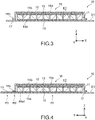
- Fig. 3 is a cross-sectional view of the thermoelectric conversion module 10 taken along the line A-A' of Fig. 1 .
- Fig. 4 is a cross-sectional view of the thermoelectric conversion module 10 taken along the line B-B' of Fig. 1 .
- the near side in the Y-axis direction is defined as the front side
- the deep side in the Y-axis direction is defined as the back side in Figs. 1 and 2 .
- the thermoelectric conversion module 10 includes a plurality of thermoelectric elements 11 and a second substrate 13.
- the second substrate 13 is a rectangular flat plate having a smaller dimension in the X-axis and Y-axis directions than the first substrate 12, and is opposed to the central region along the XY plane in the first substrate 12 upward in the Z-axis direction.
- the plurality of thermoelectric elements 11 are arranged between the first substrate 12 and the second substrate 13.
- the cover portion 16 seals the second substrate 13 and the plurality of thermoelectric elements 11 in the housing portion 16a.
- the cover portion 16 has a protective function of sealing and protecting the plurality of thermoelectric elements 11 from the external environment.
- the plurality of thermoelectric elements 11 housed in the housing portion 16a are not affected by the outside separated by the cover portion 16, reduction in thermoelectric conversion performance due to deterioration of the plurality of thermoelectric elements 11 is hardly caused regardless of the use environment.
- the cover portion 16 can be formed of any material, but it is favorable to be formed of a metal foil of aluminum, aluminum alloy, stainless steel, or the like. This provides the cover portion 16 with high heat resistance and corrosion resistance, so that it is possible to maintain the protective function of the plurality of thermoelectric elements 11 over a long period of time. Further, the cover portion 16 formed of a metal foil is less likely to inhibit the thermoelectric conversion performance of the thermoelectric conversion module 10 because of having the small thermal resistance.
- the thickness of the metal foil forming the cover portion 16 is favorably 100 ⁇ m or more and 250 ⁇ m or less, and more favorably 150 ⁇ m or more and 200 ⁇ m or less.
- the cover portion 16 is formed of a metal foil as described above, the weight of the thermoelectric conversion module 10 can be reduced. Further, since the cover portion 16 formed of a metal foil has flexibility, the load due to thermal expansion and thermal contraction of the cover portion 16 is hardly applied to the first substrate 12 during use of the thermoelectric conversion module 10. In addition to the above, if the cover portion 16 is formed of a metal foil, the raw material cost can be reduced.
- the first substrate 12 and the second substrate 13 are each formed of an insulating material.
- each of the first substrate 12 and the second substrate 13 can be a ceramic substrate, a resin substrate, a glass substrate, a glass epoxy substrate, or the like.
- the ceramic substrate include an aluminum nitride substrate and an aluminum oxide substrate.
- different types of substrates from each other may be used for the first substrate 12 and the second substrate 13.
- the first substrate 12 is configured as, for example, a low-temperature-side substrate to be connected to a low-temperature-side heat exchanger, and has a first electrode surface E1 facing upward in the Z-axis direction.
- the second substrate 13 is configured as, for example, a high-temperature-side substrate to be connected to a high-temperature-side heat exchanger, and has a second electrode surface E2 facing downward in the Z-axis direction.
- a plurality of first electrodes 14a are arranged in a region of the first electrode surface E1 of the first substrate 12, the region facing the second electrode surface E2 of the second substrate 13.
- a plurality of second electrodes 14b are arranged on the second electrode surface E2 of the second substrate 13.
- the first electrode 14a and the second electrode 14b can be formed of, for example, gold (Au), nickel (Ni), tin (Sn), copper (Cu), or an alloy thereof.
- the first electrode 14a and the second electrode 14b can have a single-layer structure or can have a multilayer structure in which a plurality of types of metal layers are combined.
- the first electrode 14a and the second electrode 14b can be formed by a plating method, but another method such as a direct bonding of copper (DBC) may be used.
- thermoelectric conversion module 10 include a heat transfer layer 18 provided between the second substrate 13 and the cover portion 16.
- the heat transfer layer 18 is in close contact with both the second substrate 13 and the cover portion 16.
- the heat transfer layer 18 has an action of reducing the thermal resistance between the cover portion 16 and the second substrate 13.
- the heat transfer layer 18 can be formed of, for example, silicon grease, a graphite sheet, or a thermally conductive adhesive.
- the plurality of thermoelectric elements 11 are formed of P-type thermoelectric elements and N-type thermoelectric elements.
- the P-type thermoelectric elements and the N-type thermoelectric elements in the plurality of thermoelectric elements 11 are alternately arranged along the X-axis direction and the Y-axis direction between the first substrate 12 and the second substrate 13.
- the plurality of thermoelectric elements 11 are bonded to the first electrodes 14a and the second electrodes 14b by, for example, a known bonding material such as solder, a brazing material, or an electrically conductive paste.
- Fig. 5 is a plan view showing the first electrode surface E1 of the first substrate 12.
- Fig. 6 is a plan view showing the second electrode surface E2 of the second substrate 13. Note that Figs. 5 and 6 show the positions of the plurality of thermoelectric elements 11 by broken lines.
- the first electrodes 14a of the first substrate 12 and the second electrodes 14b of the second substrate 13 are patterned so as to alternately connect in series all the P-type thermoelements and the N-type thermoelectric elements that constitute the plurality of thermoelectric elements 11.
- the plurality of thermoelectric elements 11 are each formed of a thermoelectric material, that is, the P-type thermoelectric element is formed of a P-type thermoelectric material, and the N-type thermoelectric element is formed of an N-type thermoelectric material.
- the plurality of thermoelectric elements 11 may be formed of, for example, a bismuth-tellurium-based thermoelectric material, a half-Heusler-based thermoelectric material, a silicide-based thermoelectric material, a lead-tellurium-based thermoelectric material, a silicon-germanium-based thermoelectric material, a skutterudite-based thermoelectric material, or a tetrahedrite-based thermoelectric material.
- the plurality of first electrodes 14a on the first substrate 12 include a pair of first electrodes 14a1 disposed at two corners on the front side in the Y-axis direction.
- the pair of first electrodes 14a1 constitute both ends of a series connection of the plurality of thermoelectric elements 11.
- the first substrate 12 includes a pair of terminal electrodes 15 respectively drawn out from the pair of first electrodes 14a1 to the front end in the Y-axis direction.
- the pair of terminal electrodes 15 can be formed integrally with the pair of first electrodes 14a1.
- the first substrate 12 can be divided into three regions along the XY plane, that is, a first region R1, a second region R2, and a third region R3.
- the first region R1 is a region that is disposed at the center of the first substrate 12 in the X-axis direction and the Y-axis direction and closes the housing portion 16a of the cover portion 16.
- the second substrate 13 and the plurality of thermoelectric elements 11 are held on the first electrode surface E1 in the first region R1.
- the second region R2 of the first substrate 12 is a region that surrounds the periphery of the first region R1 and faces the flange portion 16b of the cover portion 16.
- the flange portion 16b of the cover portion 16 is bonded to the first electrode surface E1 in the second region R2 via the bonding member 17.
- the third region R3 of the first substrate 12 is a region outside the second region R2. In other words, the first electrode surface E1 is exposed to the external space in the third region R3.
- the pair of terminal electrodes 15 extend from the first region R1, in which the pair of first electrodes 14a1 are arranged, to the third region R3 via the second region R2.
- the pair of terminal electrodes 15 can be used as terminals in the third region R3.
- Fig. 7 is a cross-sectional view of the thermoelectric conversion module 10 taken along the line C-C' of Fig. 1 , that is, shows a cross-section of a portion through which the pair of terminal electrodes 15 pass in the second region R2.
- Fig. 8 is a view showing an enlarged region D of Fig. 7 , which includes the terminal electrode 15 and its periphery and is surrounded by a chain line.
- the bonding member 17 is sandwiched between the first electrode surface E1 and the flange portion 16b, so that it is possible to bring the bonding member 17 into close contact with a region in which the terminal electrode 15 is not held on the first electrode surface E1 of the first substrate 12.
- Fig. 8 shows a thickness T that is the dimension of the terminal electrode 15 in the Z-axis direction.
- the bonding member 17 is less likely to come into close contact along the step formed on the first electrode surface E1 due to the terminal electrode 15, and thus a gap is likely to be generated between the terminal electrode 15 and the bonding member 17. From this viewpoint, in the first substrate 12, it is favorable that the thickness T of the pair of terminal electrodes 15 be kept to 100 ⁇ m or less, and further 75 ⁇ m or less.
- the bonding member 17 can be selected as appropriate from insulating materials having physical properties such as viscosity suitable for coming into close contact with the pair of terminal electrodes 15 without a gap in an uncured state.
- insulating materials for example, a polyolefin-based resin, an epoxy resin, a polyimide resin, a urethane resin, an acrylic resin, or the like can be selected as appropriate.
- the thickness of the bonding member 17 can be determined as appropriate in accordance with the thickness T of the pair of terminal electrodes 15.
- thermoelectric conversion module 10 in the manufacturing process of the thermoelectric conversion module 10, in the process of bonding the flange portion 16b of the cover portion 16 onto the first electrode surface E1 of the first substrate 12 via the bonding member 17, the bonding member 17 can be brought into close contact with the pair of terminal electrodes 15 without a gap. Therefore, the thermoelectric conversion module 10 does not require a special process for ensuring insulation and airtightness around the pair of terminal electrodes 15.
- the first substrate 12 which is a low-temperature-side substrate, also has a function of closing, from below in the Z-axis direction, the housing portion 16a of the cover portion 16 for sealing the plurality of thermoelectric elements 11.
- the thermoelectric conversion module 10 does not need to separately include a member for closing the housing portion 16a from below in the Z-axis direction. Therefore, it is possible to reduce the manufacturing cost in the thermoelectric conversion module 10.
- thermoelectric conversion module 10 the lower surface of the first substrate 12 in the Z-axis direction is exposed to the external space, unlike the configuration in which the entire periphery is covered by a package. Therefore, in the thermoelectric conversion module 10, it is possible to seal the plurality of thermoelectric elements 11 without increasing the thermal resistance at the low-temperature side. Thus, in the thermoelectric conversion module 10, it is possible to achieve high environmental resistance while ensuring high thermoelectric conversion performance.
- thermoelectric conversion module 10 the configuration of the thermoelectric conversion module 10 described above can be variously modified in accordance with the required thermoelectric conversion performance or the like.
- the number and arrangement of the plurality of thermoelectric elements 11, the shape of the first substrate 12 and the second substrate 13, and the like can be changed from the above configuration.
- the second substrate 13 may be divided into a plurality of pieces. In the second substrate 13 having such a configuration, particularly in the case of a ceramic substrate, the amount of deformation caused by warpage due to the influence of heat can be kept small.
- the second substrate 13 may be omitted, and the second electrodes 14b may be connected to the cover portion 16 via the heat transfer layer 18.
- Insulation between the second electrodes 14b in this configuration can be achieved by, for example, a configuration in which the heat transfer layer 18 is formed of an insulating material, or a configuration in which an insulating layer different from the second substrate 13 is provided between the second electrodes 14b and the heat transfer layer 18.
- a plurality of copper pieces formed of a copper foil can be used as the second electrodes 14b of the thermoelectric conversion module 10 without using the second substrate 13 shown in Fig. 9 .
- the copper piece can be formed into the shape of the second electrode 14b by, for example, pressing or etching. Further, for positioning of the plurality of copper pieces, for example, a jig formed to correspond to a designated position in the design of the second electrode 14b can be used.
- thermoelectric conversion module 10 when a resin substrate is used as the first substrate 12 in the thermoelectric conversion module 10, as shown in Fig. 10 , it is favorable to provide a metal film 19 formed of a metal material such as copper on the lower surface of the first substrate 12 in the Z-axis direction, which is opposite to the first electrode surface E1. As a result, it is possible to prevent water vapor, oxygen, or the like from the outside from passing through the first substrate 12 formed of resin and entering the housing portion 16a of the cover portion 16.
- the metal film 19 only needs to be formed on at least a part of the first region R1 of the first substrate 12. However, it is favorable that the metal film 19 be formed over the entire first region R1 of the first substrate 12, and further favorable that the metal film extend from the first region R1 to the second region R2. In addition, the metal film 19 may be formed over the entire region of the lower surface of the first substrate 12 in the Z-axis direction without patterning.
- thermoelectric conversion module 10 it is favorable that the inside of the housing portion 16a of the cover portion 16 be a non-oxidizing atmosphere or a reduced-pressure atmosphere in which the amount of oxygen is smaller than in the atmosphere.
- the non-oxidizing atmosphere can be generated by, for example, encapsulation of an inert gas such as nitrogen or argon.
- thermoelectric conversion module 110 is a cross-sectional view of a thermoelectric conversion module 110 according to a second embodiment of the present invention.
- the configuration of a first substrate 112 is different from that of the first substrate 12 of the thermoelectric conversion module 10 according to the first embodiment, and the configuration other than the first substrate 112 is common to the thermoelectric conversion module 10 according to the first embodiment.
- the same reference numerals are used for the components similar to those of the first embodiment, and the description thereof is omitted as appropriate.
- the first substrate 112 is configured as a layered substrate having a multilayer structure including an inner layer 112a and an outer layer 112b stacked in the Z-axis direction.
- the first substrate 112 includes a terminal electrode 115 including an interlayer electrode 115a disposed between the inner layer 112a and the outer layer 112b.
- the terminal electrode 115 includes a first through electrode 115b, an electrode pad 115c, and a second through electrode 115d.
- the first through electrode 115b penetrates the inner layer 112a in the first region R1, and connects a first electrode 14a1 and the interlayer electrode 115a to each other.
- the electrode pad 115c is provided on the first electrode surface E1 in the third region R3.
- the second through electrode 115d connects the electrode pad 115c and the interlayer electrode 115a to each other.
- the electrode pad 115c on the first electrode surface E1 can be used as a terminal.
- the first substrate 112 is provided as the layered substrate and can thus have a configuration that does not cause a step due to the terminal electrode 115 on the first electrode surface E1 in the second region R2. Thus, in the first substrate 112, it is easy to ensure airtightness between the first electrode surface E1 and the flange portion 16b of the cover portion 16.
- the first substrate 112, which is a layered substrate may be configured as a general multilayer wiring substrate and may include three or more layers.
- the electrode pad 115c and the second through electrode 115d are not essential.
- the interlayer electrode 115a can be exposed by shortening the inner layer 112a in the Y-axis direction in the third region R3 of the first substrate 112.
- the thermoelectric conversion module 110 can use the interlayer electrode 115a on the outer layer 112b as a terminal.
- thermoelectric conversion module 210 is a cross-sectional view of a thermoelectric conversion module 210 according to a third embodiment of the present invention.
- the configuration of a first substrate 212 is different from that of the first substrate 12 of the thermoelectric conversion module 10 according to the first embodiment, and the configuration other than the first substrate 212 is common to the thermoelectric conversion module 10 according to the first embodiment.
- the same reference numerals are used for the components similar to those of the first embodiment, and the description thereof is omitted as appropriate.
- the first substrate 212 has a single-layer structure similarly to the first substrate 12 according to the first embodiment.
- the first substrate 212 includes a terminal electrode 215 including a back electrode 215a on a lower surface of the first substrate 212 in the Z-axis direction, which is opposite to the first electrode surface E1.
- the terminal electrode 215 includes a first through electrode 215b, an electrode pad 215c, and a second through electrode 215d.
- the first through electrode 215b penetrates the base material of the first substrate 212 in the Z-axis direction in the first region R1, and connects a first electrode 14a1 and the back electrode 215a to each other.
- the electrode pad 215c is provided on the first electrode surface E1 in the third region R3.
- the second through electrode 215d connects the electrode pad 215c and the back electrode 215a to each other.
- the electrode pad 215c on the first electrode surface E1 can be used as a terminal.
- the first substrate 212 of the thermoelectric conversion module 210 can also have a configuration that does not cause a step due to the terminal electrode 215 on the first electrode surface E1 in the second region R2.
- thermoelectric conversion module 210 the electrode pad 215c and the second through electrode 215d are not essential.
- the thermoelectric conversion module 210 may have a configuration in which the electrode pad 215c and the second through electrode 215d are omitted.
- the back surface electrode 215a on the lower surface in the Z-axis direction, which is opposite to the first electrode surface E1 of the first substrate 212, can be used as a terminal.
- thermoelectric conversion module according to the present invention may have a multistage configuration including a plurality of layers in each of which a plurality of thermoelectric elements are arranged.
- thermoelectric conversion module according to the present invention may include a cover portion divided into a plurality of portions on a first electrode surface of a single first substrate.
- the method of fixing the cover portion 16 to the first electrode surface E1 of the first substrate 12 is not limited to the configuration using the bonding member 17.
- the present invention can be configured by using, for example, a fastening member that mechanically fixes the cover portion 16 and the first substrate 12 to each other.
- a fastening member for example, a clip member can be used.
- the bonding member 17 and the fastening member may be used in combination to fix the cover portion 16 to the first electrode surface E1 of the first substrate 12.
Landscapes
- Cooling Or The Like Of Semiconductors Or Solid State Devices (AREA)
Abstract
Description
- The present invention relates to a thermoelectric conversion module having excellent environmental resistance.
- The thermoelectric conversion modules are available as cooling modules utilizing the Peltier effect of thermoelectric materials and as power generation modules utilizing the Seebeck effect of thermoelectric materials. With the expansion of applications of thermoelectric conversion modules and the like, the thermoelectric conversion modules have been more utilized in various environments. In the thermoelectric conversion modules, deterioration caused by the external environment, such as oxidation or corrosion, in thermoelectric elements formed of thermoelectric materials causes reduction in thermoelectric conversion performance.
- Patent Literature 1 discloses a thermoelectric conversion module capable of preventing deterioration caused by the external environment in thermoelectric elements. The thermoelectric conversion module has a configuration that is hermetically covered with a package formed of a plate material of metal, and in which only a lead wire is drawn outside the package. In such a thermoelectric conversion module, excellent environmental resistance is obtained, because the thermoelectric elements in the package separated from the outside are not affected by the external environment.
- Patent Literature 1:
Japanese Patent Application Laid-open No. 2006-49872 - However, in the thermoelectric conversion module according to the above document, both the lead wire and the package are formed of metal. So, this thermoelectric conversion module needs a configuration for electrically insulating the lead wire and the package from each other and for hermetically sealing a gap between the lead wire and the package. For that reason, in this thermoelectric conversion module, the manufacturing process is complicated and the manufacturing cost is increased.
- In view of the above circumstances, it is an object of the present invention to provide a technique for sealing a plurality of thermoelectric elements in a thermoelectric conversion module.
- To achieve the above object, a thermoelectric conversion module according to an embodiment of the present invention includes a substrate, a plurality of second electrodes, a plurality of thermoelectric elements, a cover portion, and a pair of terminal electrodes.
- The substrate has an electrode surface on which a plurality of first electrodes are provided.
- The plurality of second electrodes face the plurality of first electrodes.
- The plurality of thermoelectric elements are disposed between the plurality of first electrodes and the plurality of second electrodes and include P-type thermoelectric elements and N-type thermoelectric elements alternately connected in series using the plurality of first electrodes and the plurality of second electrodes.
- The cover portion seals the plurality of second electrodes and the plurality of thermoelectric elements on the electrode surface.
- The pair of terminal electrodes are provided on the substrate and drawn outside the cover portion from a pair of first electrodes in the plurality of first electrodes, the pair of first electrodes constituting both ends of a series connection of the plurality of thermoelectric elements.
- The substrate may include a first region in which the plurality of thermoelectric elements are disposed, a second region that surrounds the first region and to which the cover portion is bonded, and a third region outside the second region.
- The pair of terminal electrodes may be drawn out from the first region to the third region via the second region.
- The pair of terminal electrodes may be provided on the electrode surface and have a thickness of 100 µm or less.
- The substrate may be configured as a layered substrate. In this case, each of the pair of terminal electrodes may include an interlayer electrode, and a through electrode that connects one of the pair of first electrodes and the interlayer electrode to each other.
- Each of the pair of terminal electrodes may include a back electrode provided on a surface opposite to the electrode surface in the substrate, and a through electrode that connects one of the pair of first electrodes and the back electrode to each other.
- The substrate may be configured as a resin substrate including a metal film provided on a surface opposite to the electrode surface.
- The substrate may be a low-temperature-side substrate.
- The thermoelectric conversion module may further include a fastening member that mechanically fixes the substrate and the cover portion to each other.
-
- [
Fig. 1] Fig. 1 is a perspective view of a thermoelectric conversion module according to a first embodiment of the present invention. - [
Fig. 2] Fig. 2 is an exploded perspective view of the thermoelectric conversion module. - [
Fig. 3] Fig. 3 is a cross-sectional view of the thermoelectric conversion module taken along the line A-A' ofFig. 1 . - [
Fig. 4] Fig. 4 is a cross-sectional view of the thermoelectric conversion module taken along the line B-B' ofFig. 1 . - [
Fig. 5] Fig. 5 is a plan view of a first electrode surface of a first substrate of the thermoelectric conversion module. - [
Fig. 6] Fig. 6 is a plan view of a second electrode surface of a second substrate of the thermoelectric conversion module. - [
Fig. 7] Fig. 7 is a cross-sectional view of the thermoelectric conversion module taken along the line C-C' ofFig. 1 . - [
Fig. 8] Fig. 8 is a partial cross-sectional view of the thermoelectric conversion module showing an enlarged region D ofFig. 7 . - [
Fig. 9] Fig. 9 is a cross-sectional view of a modification of the thermoelectric conversion module. - [
Fig. 10] Fig. 10 is a cross-sectional view of a modification of the thermoelectric conversion module. - [
Fig. 11] Fig. 11 is a cross-sectional view of a thermoelectric conversion module according to a second embodiment of the present invention. - [
Fig. 12] Fig. 12 is a cross-sectional view of a modification of the thermoelectric conversion module. - [
Fig. 13] Fig. 13 is a cross-sectional view of a thermoelectric conversion module according to a third embodiment of the present invention. - [
Fig. 14] Fig. 14 is a cross-sectional view of a modification of the thermoelectric conversion module. Mode(s) for Carrying Out the Invention - Hereinafter, embodiments of the present invention will be described with reference to the drawings.
- The X-axis, the Y-axis, and the Z-axis, which are orthogonal to each other as appropriate, are shown in the drawings. The X-axis, the Y-axis, and the Z-axis are common in all figures.
-
Fig. 1 is a perspective view of athermoelectric conversion module 10 according to a first embodiment of the present invention. Thethermoelectric conversion module 10 includes afirst substrate 12 and acover portion 16. Thefirst substrate 12 is a rectangular flat plate extending along the X-axis and Y-axis directions and constitutes the lower surface of thethermoelectric conversion module 10 in the Z-axis direction. Thecover portion 16 has a flat shape along the XY plane and covers thefirst substrate 12 from above in the Z-axis direction. - The
cover portion 16 includes ahousing portion 16a and aflange portion 16b. Thehousing portion 16a forms a rectangular inner space, which extends along the X-axis and Y-axis directions and is opened downward in the Z-axis direction. Theflange portion 16b extends outward in the X-axis and Y-axis directions from the lower end portion of thehousing portion 16a, which is opened in the Z-axis direction. Thecover portion 16 is bonded to thefirst substrate 12 without a gap via abonding member 17 over the entire circumference of theflange portion 16b. - The
cover portion 16 includes theflange portion 16b, which makes it possible to ensure a large bonding area with respect to thefirst substrate 12 via thebonding member 17. Thus, in thecover portion 16, a gap is less likely to be generated between theflange portion 16b and thefirst substrate 12. From this viewpoint, the dimension of theflange portion 16b extending in the X-axis and the Y-axis directions from thehousing portion 16a is favorably 1 mm or more, and more favorably 3 mm or more. -
Fig. 2 is an exploded perspective view showing a state of thethermoelectric conversion module 10, in which thecover portion 16 bonded via thebonding member 17 is detached from thefirst substrate 12.Fig. 3 is a cross-sectional view of thethermoelectric conversion module 10 taken along the line A-A' ofFig. 1 .Fig. 4 is a cross-sectional view of thethermoelectric conversion module 10 taken along the line B-B' ofFig. 1 . Nota that, in the following description, the near side in the Y-axis direction is defined as the front side, and the deep side in the Y-axis direction is defined as the back side inFigs. 1 and 2 . - The
thermoelectric conversion module 10 includes a plurality ofthermoelectric elements 11 and asecond substrate 13. Thesecond substrate 13 is a rectangular flat plate having a smaller dimension in the X-axis and Y-axis directions than thefirst substrate 12, and is opposed to the central region along the XY plane in thefirst substrate 12 upward in the Z-axis direction. The plurality ofthermoelectric elements 11 are arranged between thefirst substrate 12 and thesecond substrate 13. Thecover portion 16 seals thesecond substrate 13 and the plurality ofthermoelectric elements 11 in thehousing portion 16a. - In the
thermoelectric conversion module 10, thecover portion 16 has a protective function of sealing and protecting the plurality ofthermoelectric elements 11 from the external environment. In other words, in thethermoelectric conversion module 10, since the plurality ofthermoelectric elements 11 housed in thehousing portion 16a are not affected by the outside separated by thecover portion 16, reduction in thermoelectric conversion performance due to deterioration of the plurality ofthermoelectric elements 11 is hardly caused regardless of the use environment. - The
cover portion 16 can be formed of any material, but it is favorable to be formed of a metal foil of aluminum, aluminum alloy, stainless steel, or the like. This provides thecover portion 16 with high heat resistance and corrosion resistance, so that it is possible to maintain the protective function of the plurality ofthermoelectric elements 11 over a long period of time. Further, thecover portion 16 formed of a metal foil is less likely to inhibit the thermoelectric conversion performance of thethermoelectric conversion module 10 because of having the small thermal resistance. The thickness of the metal foil forming thecover portion 16 is favorably 100 µm or more and 250 µm or less, and more favorably 150 µm or more and 200 µm or less. - Furthermore, if the
cover portion 16 is formed of a metal foil as described above, the weight of thethermoelectric conversion module 10 can be reduced. Further, since thecover portion 16 formed of a metal foil has flexibility, the load due to thermal expansion and thermal contraction of thecover portion 16 is hardly applied to thefirst substrate 12 during use of thethermoelectric conversion module 10. In addition to the above, if thecover portion 16 is formed of a metal foil, the raw material cost can be reduced. - The
first substrate 12 and thesecond substrate 13 are each formed of an insulating material. For example, each of thefirst substrate 12 and thesecond substrate 13 can be a ceramic substrate, a resin substrate, a glass substrate, a glass epoxy substrate, or the like. Examples of the ceramic substrate include an aluminum nitride substrate and an aluminum oxide substrate. Further, in thethermoelectric conversion module 10, different types of substrates from each other may be used for thefirst substrate 12 and thesecond substrate 13. - The
first substrate 12 is configured as, for example, a low-temperature-side substrate to be connected to a low-temperature-side heat exchanger, and has a first electrode surface E1 facing upward in the Z-axis direction. Thesecond substrate 13 is configured as, for example, a high-temperature-side substrate to be connected to a high-temperature-side heat exchanger, and has a second electrode surface E2 facing downward in the Z-axis direction. A plurality offirst electrodes 14a are arranged in a region of the first electrode surface E1 of thefirst substrate 12, the region facing the second electrode surface E2 of thesecond substrate 13. A plurality ofsecond electrodes 14b are arranged on the second electrode surface E2 of thesecond substrate 13. - The
first electrode 14a and thesecond electrode 14b can be formed of, for example, gold (Au), nickel (Ni), tin (Sn), copper (Cu), or an alloy thereof. Thefirst electrode 14a and thesecond electrode 14b can have a single-layer structure or can have a multilayer structure in which a plurality of types of metal layers are combined. Thefirst electrode 14a and thesecond electrode 14b can be formed by a plating method, but another method such as a direct bonding of copper (DBC) may be used. - As shown in
Figs. 3 and 4 , it is favorable that thethermoelectric conversion module 10 include aheat transfer layer 18 provided between thesecond substrate 13 and thecover portion 16. Theheat transfer layer 18 is in close contact with both thesecond substrate 13 and thecover portion 16. Theheat transfer layer 18 has an action of reducing the thermal resistance between thecover portion 16 and thesecond substrate 13. Theheat transfer layer 18 can be formed of, for example, silicon grease, a graphite sheet, or a thermally conductive adhesive. - The plurality of
thermoelectric elements 11 are formed of P-type thermoelectric elements and N-type thermoelectric elements. The P-type thermoelectric elements and the N-type thermoelectric elements in the plurality ofthermoelectric elements 11 are alternately arranged along the X-axis direction and the Y-axis direction between thefirst substrate 12 and thesecond substrate 13. The plurality ofthermoelectric elements 11 are bonded to thefirst electrodes 14a and thesecond electrodes 14b by, for example, a known bonding material such as solder, a brazing material, or an electrically conductive paste. -
Fig. 5 is a plan view showing the first electrode surface E1 of thefirst substrate 12.Fig. 6 is a plan view showing the second electrode surface E2 of thesecond substrate 13. Note thatFigs. 5 and 6 show the positions of the plurality ofthermoelectric elements 11 by broken lines. Thefirst electrodes 14a of thefirst substrate 12 and thesecond electrodes 14b of thesecond substrate 13 are patterned so as to alternately connect in series all the P-type thermoelements and the N-type thermoelectric elements that constitute the plurality ofthermoelectric elements 11. - The plurality of
thermoelectric elements 11 are each formed of a thermoelectric material, that is, the P-type thermoelectric element is formed of a P-type thermoelectric material, and the N-type thermoelectric element is formed of an N-type thermoelectric material. The plurality ofthermoelectric elements 11 may be formed of, for example, a bismuth-tellurium-based thermoelectric material, a half-Heusler-based thermoelectric material, a silicide-based thermoelectric material, a lead-tellurium-based thermoelectric material, a silicon-germanium-based thermoelectric material, a skutterudite-based thermoelectric material, or a tetrahedrite-based thermoelectric material. - The plurality of
first electrodes 14a on thefirst substrate 12 include a pair of first electrodes 14a1 disposed at two corners on the front side in the Y-axis direction. The pair of first electrodes 14a1 constitute both ends of a series connection of the plurality ofthermoelectric elements 11. Thefirst substrate 12 includes a pair ofterminal electrodes 15 respectively drawn out from the pair of first electrodes 14a1 to the front end in the Y-axis direction. The pair ofterminal electrodes 15 can be formed integrally with the pair of first electrodes 14a1. - As shown in
Fig. 5 , thefirst substrate 12 can be divided into three regions along the XY plane, that is, a first region R1, a second region R2, and a third region R3. The first region R1 is a region that is disposed at the center of thefirst substrate 12 in the X-axis direction and the Y-axis direction and closes thehousing portion 16a of thecover portion 16. In other words, thesecond substrate 13 and the plurality ofthermoelectric elements 11 are held on the first electrode surface E1 in the first region R1. - The second region R2 of the
first substrate 12 is a region that surrounds the periphery of the first region R1 and faces theflange portion 16b of thecover portion 16. In other words, theflange portion 16b of thecover portion 16 is bonded to the first electrode surface E1 in the second region R2 via thebonding member 17. The third region R3 of thefirst substrate 12 is a region outside the second region R2. In other words, the first electrode surface E1 is exposed to the external space in the third region R3. - As shown in
Fig. 5 , the pair ofterminal electrodes 15 extend from the first region R1, in which the pair of first electrodes 14a1 are arranged, to the third region R3 via the second region R2. In thethermoelectric conversion module 10, the pair ofterminal electrodes 15 can be used as terminals in the third region R3.Fig. 7 is a cross-sectional view of thethermoelectric conversion module 10 taken along the line C-C' ofFig. 1 , that is, shows a cross-section of a portion through which the pair ofterminal electrodes 15 pass in the second region R2. - As shown in
Fig. 7 , the pair ofterminal electrodes 15 penetrate thebonding member 17 in the Y-axis direction in the second region R2.Fig. 8 is a view showing an enlarged region D ofFig. 7 , which includes theterminal electrode 15 and its periphery and is surrounded by a chain line. In thethermoelectric conversion module 10, the bondingmember 17 is sandwiched between the first electrode surface E1 and theflange portion 16b, so that it is possible to bring thebonding member 17 into close contact with a region in which theterminal electrode 15 is not held on the first electrode surface E1 of thefirst substrate 12. -
Fig. 8 shows a thickness T that is the dimension of theterminal electrode 15 in the Z-axis direction. In thefirst substrate 12, as the thickness T of theterminal electrode 15 becomes larger, the bondingmember 17 is less likely to come into close contact along the step formed on the first electrode surface E1 due to theterminal electrode 15, and thus a gap is likely to be generated between theterminal electrode 15 and thebonding member 17. From this viewpoint, in thefirst substrate 12, it is favorable that the thickness T of the pair ofterminal electrodes 15 be kept to 100 µm or less, and further 75 µm or less. - The bonding
member 17 can be selected as appropriate from insulating materials having physical properties such as viscosity suitable for coming into close contact with the pair ofterminal electrodes 15 without a gap in an uncured state. As such insulating materials, for example, a polyolefin-based resin, an epoxy resin, a polyimide resin, a urethane resin, an acrylic resin, or the like can be selected as appropriate. Further, the thickness of thebonding member 17 can be determined as appropriate in accordance with the thickness T of the pair ofterminal electrodes 15. - In the manufacturing process of the
thermoelectric conversion module 10, in the process of bonding theflange portion 16b of thecover portion 16 onto the first electrode surface E1 of thefirst substrate 12 via thebonding member 17, the bondingmember 17 can be brought into close contact with the pair ofterminal electrodes 15 without a gap. Therefore, thethermoelectric conversion module 10 does not require a special process for ensuring insulation and airtightness around the pair ofterminal electrodes 15. - Further, in the
thermoelectric conversion module 10, thefirst substrate 12, which is a low-temperature-side substrate, also has a function of closing, from below in the Z-axis direction, thehousing portion 16a of thecover portion 16 for sealing the plurality ofthermoelectric elements 11. Thus, thethermoelectric conversion module 10 does not need to separately include a member for closing thehousing portion 16a from below in the Z-axis direction. Therefore, it is possible to reduce the manufacturing cost in thethermoelectric conversion module 10. - Furthermore, in the
thermoelectric conversion module 10, the lower surface of thefirst substrate 12 in the Z-axis direction is exposed to the external space, unlike the configuration in which the entire periphery is covered by a package. Therefore, in thethermoelectric conversion module 10, it is possible to seal the plurality ofthermoelectric elements 11 without increasing the thermal resistance at the low-temperature side. Thus, in thethermoelectric conversion module 10, it is possible to achieve high environmental resistance while ensuring high thermoelectric conversion performance. - Of course, the configuration of the
thermoelectric conversion module 10 described above can be variously modified in accordance with the required thermoelectric conversion performance or the like. For example, in thethermoelectric conversion module 10, the number and arrangement of the plurality ofthermoelectric elements 11, the shape of thefirst substrate 12 and thesecond substrate 13, and the like can be changed from the above configuration. Further, in thethermoelectric conversion module 10, thesecond substrate 13 may be divided into a plurality of pieces. In thesecond substrate 13 having such a configuration, particularly in the case of a ceramic substrate, the amount of deformation caused by warpage due to the influence of heat can be kept small. - Furthermore, in the
thermoelectric conversion module 10, as shown inFig. 9 , thesecond substrate 13 may be omitted, and thesecond electrodes 14b may be connected to thecover portion 16 via theheat transfer layer 18. Insulation between thesecond electrodes 14b in this configuration can be achieved by, for example, a configuration in which theheat transfer layer 18 is formed of an insulating material, or a configuration in which an insulating layer different from thesecond substrate 13 is provided between thesecond electrodes 14b and theheat transfer layer 18. - As the
second electrodes 14b of thethermoelectric conversion module 10 without using thesecond substrate 13 shown inFig. 9 , for example, a plurality of copper pieces formed of a copper foil can be used. The copper piece can be formed into the shape of thesecond electrode 14b by, for example, pressing or etching. Further, for positioning of the plurality of copper pieces, for example, a jig formed to correspond to a designated position in the design of thesecond electrode 14b can be used. - Further, when a resin substrate is used as the
first substrate 12 in thethermoelectric conversion module 10, as shown inFig. 10 , it is favorable to provide ametal film 19 formed of a metal material such as copper on the lower surface of thefirst substrate 12 in the Z-axis direction, which is opposite to the first electrode surface E1. As a result, it is possible to prevent water vapor, oxygen, or the like from the outside from passing through thefirst substrate 12 formed of resin and entering thehousing portion 16a of thecover portion 16. - In this configuration, the
metal film 19 only needs to be formed on at least a part of the first region R1 of thefirst substrate 12. However, it is favorable that themetal film 19 be formed over the entire first region R1 of thefirst substrate 12, and further favorable that the metal film extend from the first region R1 to the second region R2. In addition, themetal film 19 may be formed over the entire region of the lower surface of thefirst substrate 12 in the Z-axis direction without patterning. - Further, in the
thermoelectric conversion module 10, it is favorable that the inside of thehousing portion 16a of thecover portion 16 be a non-oxidizing atmosphere or a reduced-pressure atmosphere in which the amount of oxygen is smaller than in the atmosphere. Thus, it is possible to prevent an increase in the electrical resistance of thethermoelectric conversion module 10 due to oxidation of the plurality ofthermoelectric elements 11. The non-oxidizing atmosphere can be generated by, for example, encapsulation of an inert gas such as nitrogen or argon. -
Fig. 11 is a cross-sectional view of athermoelectric conversion module 110 according to a second embodiment of the present invention. In thethermoelectric conversion module 110, the configuration of afirst substrate 112 is different from that of thefirst substrate 12 of thethermoelectric conversion module 10 according to the first embodiment, and the configuration other than thefirst substrate 112 is common to thethermoelectric conversion module 10 according to the first embodiment. In this embodiment, the same reference numerals are used for the components similar to those of the first embodiment, and the description thereof is omitted as appropriate. - In the
thermoelectric conversion module 110, thefirst substrate 112 is configured as a layered substrate having a multilayer structure including aninner layer 112a and anouter layer 112b stacked in the Z-axis direction. Thefirst substrate 112 includes aterminal electrode 115 including aninterlayer electrode 115a disposed between theinner layer 112a and theouter layer 112b. In addition to theinterlayer electrode 115a, theterminal electrode 115 includes a first throughelectrode 115b, anelectrode pad 115c, and a second throughelectrode 115d. - The first through
electrode 115b penetrates theinner layer 112a in the first region R1, and connects a first electrode 14a1 and theinterlayer electrode 115a to each other. Theelectrode pad 115c is provided on the first electrode surface E1 in the third region R3. The second throughelectrode 115d connects theelectrode pad 115c and theinterlayer electrode 115a to each other. Thus, in thethermoelectric conversion module 110, theelectrode pad 115c on the first electrode surface E1 can be used as a terminal. - The
first substrate 112 is provided as the layered substrate and can thus have a configuration that does not cause a step due to theterminal electrode 115 on the first electrode surface E1 in the second region R2. Thus, in thefirst substrate 112, it is easy to ensure airtightness between the first electrode surface E1 and theflange portion 16b of thecover portion 16. Note that thefirst substrate 112, which is a layered substrate, may be configured as a general multilayer wiring substrate and may include three or more layers. - Further, in the
thermoelectric conversion module 110, theelectrode pad 115c and the second throughelectrode 115d are not essential. For example, in thethermoelectric conversion module 110, as shown inFig. 12 , theinterlayer electrode 115a can be exposed by shortening theinner layer 112a in the Y-axis direction in the third region R3 of thefirst substrate 112. In this case, thethermoelectric conversion module 110 can use theinterlayer electrode 115a on theouter layer 112b as a terminal. -
Fig. 13 is a cross-sectional view of athermoelectric conversion module 210 according to a third embodiment of the present invention. In thethermoelectric conversion module 210, the configuration of afirst substrate 212 is different from that of thefirst substrate 12 of thethermoelectric conversion module 10 according to the first embodiment, and the configuration other than thefirst substrate 212 is common to thethermoelectric conversion module 10 according to the first embodiment. In this embodiment, the same reference numerals are used for the components similar to those of the first embodiment, and the description thereof is omitted as appropriate. - In the
thermoelectric conversion module 210, thefirst substrate 212 has a single-layer structure similarly to thefirst substrate 12 according to the first embodiment. Thefirst substrate 212 includes aterminal electrode 215 including aback electrode 215a on a lower surface of thefirst substrate 212 in the Z-axis direction, which is opposite to the first electrode surface E1. In addition to theback electrode 215a, theterminal electrode 215 includes a first throughelectrode 215b, anelectrode pad 215c, and a second throughelectrode 215d. - The first through
electrode 215b penetrates the base material of thefirst substrate 212 in the Z-axis direction in the first region R1, and connects a first electrode 14a1 and theback electrode 215a to each other. Theelectrode pad 215c is provided on the first electrode surface E1 in the third region R3. The second throughelectrode 215d connects theelectrode pad 215c and theback electrode 215a to each other. Thus, in thethermoelectric conversion module 210, theelectrode pad 215c on the first electrode surface E1 can be used as a terminal. - Similarly to the
first substrate 112 of thethermoelectric conversion module 110 according to the second embodiment, thefirst substrate 212 of thethermoelectric conversion module 210 according to this embodiment can also have a configuration that does not cause a step due to theterminal electrode 215 on the first electrode surface E1 in the second region R2. Thus, similarly to the above, it is easy to ensure airtightness between the first electrode surface E1 and theflange portion 16b of thecover portion 16 also in thefirst substrate 212. - Further, in the
thermoelectric conversion module 210, theelectrode pad 215c and the second throughelectrode 215d are not essential. In other words, as shown inFig. 14 , thethermoelectric conversion module 210 may have a configuration in which theelectrode pad 215c and the second throughelectrode 215d are omitted. In this case, in thethermoelectric conversion module 210, theback surface electrode 215a on the lower surface in the Z-axis direction, which is opposite to the first electrode surface E1 of thefirst substrate 212, can be used as a terminal. - Hereinabove, the embodiments of the present invention have been described, but the present invention is not limited to the embodiments described above and can be variously modified without departing from the gist of the present invention.
- For example, in the above embodiments, the configuration including a single layer in which a plurality of thermoelectric elements are arranged has been described, but the thermoelectric conversion module according to the present invention may have a multistage configuration including a plurality of layers in each of which a plurality of thermoelectric elements are arranged. Further, in the above embodiments, the configuration including a single cover portion has been described, but the thermoelectric conversion module according to the present invention may include a cover portion divided into a plurality of portions on a first electrode surface of a single first substrate.
- Further, in the present invention, the method of fixing the
cover portion 16 to the first electrode surface E1 of thefirst substrate 12 is not limited to the configuration using thebonding member 17. The present invention can be configured by using, for example, a fastening member that mechanically fixes thecover portion 16 and thefirst substrate 12 to each other. As the fastening member, for example, a clip member can be used. In this case, by sandwiching theflange portion 16b of thecover portion 16 and thefirst substrate 12 from the outside by using a clip member, it is possible to mechanically fix thecover portion 16 to the first electrode surface E1 of thefirst substrate 12. Note that the bondingmember 17 and the fastening member may be used in combination to fix thecover portion 16 to the first electrode surface E1 of thefirst substrate 12. -
- 10
- thermoelectric conversion module
- 11
- thermoelectric element
- 12
- first substrate
- 13
- second substrate
- 14a, 14a1
- first electrode
- 14b
- second electrode
- 15
- terminal electrode
- 16
- cover portion
- 16a
- housing portion
- 16b
- flange portion
- 17
- bonding member
- 18
- heat transfer layer
- 19
- metal film
- E1
- first electrode surface
- E2
- second electrode surface
- R1
- first region
- R2
- second region
- R3
- third region
Claims (8)
- A thermoelectric conversion module, comprising:a substrate having an electrode surface on which a plurality of first electrodes are provided;a plurality of second electrodes facing the plurality of first electrodes;a plurality of thermoelectric elements disposed between the plurality of first electrodes and the plurality of second electrodes and including P-type thermoelectric elements and N-type thermoelectric elements alternately connected in series using the plurality of first electrodes and the plurality of second electrodes;a cover portion that seals the plurality of second electrodes and the plurality of thermoelectric elements on the electrode surface; anda pair of terminal electrodes provided on the substrate and drawn outside the cover portion from a pair of first electrodes in the plurality of first electrodes, the pair of first electrodes constituting both ends of a series connection of the plurality of thermoelectric elements.
- The thermoelectric conversion module according to claim 1, whereinthe substrate includesa first region in which the plurality of thermoelectric elements are disposed,a second region that surrounds the first region and to which the cover portion is bonded, anda third region outside the second region,whereinthe pair of terminal electrodes are drawn out from the first region to the third region via the second region.
- The thermoelectric conversion module according to claim 2, wherein
the pair of terminal electrodes are provided on the electrode surface and have a thickness of 100 µm or less. - The thermoelectric conversion module according to claim 2, whereinthe substrate is configured as a layered substrate, andeach of the pair of terminal electrodes includesan interlayer electrode, anda through electrode that connects one of the pair of first electrodes and the interlayer electrode to each other.
- The thermoelectric conversion module according to claim 2, wherein
each of the pair of terminal electrodes includesa back electrode provided on a surface opposite to the electrode surface in the substrate, anda through electrode that connects one of the pair of first electrodes and the back electrode to each other. - The thermoelectric conversion module according to any one of claims 2 to 5, wherein
the substrate is configured as a resin substrate including a metal film provided on a surface opposite to the electrode surface. - The thermoelectric conversion module according to any one of claims 1 to 6, wherein
the substrate is a low-temperature-side substrate. - The thermoelectric conversion module according to any one of claims 1 to 7, further comprising
a fastening member that mechanically fixes the substrate and the cover portion to each other.
Applications Claiming Priority (2)
| Application Number | Priority Date | Filing Date | Title |
|---|---|---|---|
| JP2019170655 | 2019-09-19 | ||
| PCT/JP2020/032632 WO2021054087A1 (en) | 2019-09-19 | 2020-08-28 | Thermoelectric conversion module |
Publications (2)
| Publication Number | Publication Date |
|---|---|
| EP4033550A1 true EP4033550A1 (en) | 2022-07-27 |
| EP4033550A4 EP4033550A4 (en) | 2023-10-04 |
Family
ID=74883462
Family Applications (1)
| Application Number | Title | Priority Date | Filing Date |
|---|---|---|---|
| EP20866672.7A Pending EP4033550A4 (en) | 2019-09-19 | 2020-08-28 | THERMOELECTRIC CONVERSION MODULE |
Country Status (6)
| Country | Link |
|---|---|
| US (1) | US20220149260A1 (en) |
| EP (1) | EP4033550A4 (en) |
| JP (1) | JP7684544B2 (en) |
| KR (1) | KR20220018026A (en) |
| CN (1) | CN114080695A (en) |
| WO (1) | WO2021054087A1 (en) |
Family Cites Families (12)
| Publication number | Priority date | Publication date | Assignee | Title |
|---|---|---|---|---|
| JP2005072391A (en) * | 2003-08-26 | 2005-03-17 | Kyocera Corp | N-type thermoelectric material, manufacturing method thereof, and N-type thermoelectric element |
| JP4829552B2 (en) | 2004-07-06 | 2011-12-07 | 財団法人電力中央研究所 | Thermoelectric conversion module |
| JP2006073632A (en) * | 2004-08-31 | 2006-03-16 | Toshiba Corp | Thermoelectric conversion device and method of manufacturing thermoelectric conversion device |
| JP4686171B2 (en) * | 2004-10-29 | 2011-05-18 | 株式会社東芝 | Thermal-electrical direct conversion device |
| JP4901350B2 (en) * | 2005-08-02 | 2012-03-21 | 株式会社東芝 | Thermoelectric conversion device and manufacturing method thereof |
| JP6010941B2 (en) * | 2012-03-15 | 2016-10-19 | 日立化成株式会社 | Thermoelectric conversion module with airtight case |
| US20180090660A1 (en) * | 2013-12-06 | 2018-03-29 | Sridhar Kasichainula | Flexible thin-film based thermoelectric device with sputter deposited layer of n-type and p-type thermoelectric legs |
| JP6471241B2 (en) * | 2015-09-28 | 2019-02-13 | 京セラ株式会社 | Thermoelectric module |
| KR20170061454A (en) * | 2015-11-26 | 2017-06-05 | 현대자동차주식회사 | Thermoelectric generating system |
| CN109075245A (en) * | 2016-04-15 | 2018-12-21 | 雅马哈株式会社 | Thermo-electric conversion module encapsulation |
| KR101827120B1 (en) * | 2016-05-30 | 2018-02-07 | 현대자동차주식회사 | Housing for thermoelectric module |
| JP2018049886A (en) * | 2016-09-20 | 2018-03-29 | 昭和電工株式会社 | Thermoelectric conversion device |
-
2020
- 2020-08-28 EP EP20866672.7A patent/EP4033550A4/en active Pending
- 2020-08-28 KR KR1020227000501A patent/KR20220018026A/en not_active Ceased
- 2020-08-28 WO PCT/JP2020/032632 patent/WO2021054087A1/en not_active Ceased
- 2020-08-28 CN CN202080049211.8A patent/CN114080695A/en active Pending
- 2020-08-28 JP JP2021546575A patent/JP7684544B2/en active Active
-
2022
- 2022-01-26 US US17/584,995 patent/US20220149260A1/en active Pending
Also Published As
| Publication number | Publication date |
|---|---|
| US20220149260A1 (en) | 2022-05-12 |
| JP7684544B2 (en) | 2025-05-28 |
| KR20220018026A (en) | 2022-02-14 |
| CN114080695A (en) | 2022-02-22 |
| JPWO2021054087A1 (en) | 2021-03-25 |
| WO2021054087A1 (en) | 2021-03-25 |
| EP4033550A4 (en) | 2023-10-04 |
Similar Documents
| Publication | Publication Date | Title |
|---|---|---|
| US10665768B2 (en) | Thermoelectric conversion module package | |
| JP4901350B2 (en) | Thermoelectric conversion device and manufacturing method thereof | |
| US6314741B1 (en) | Thermoelectric device | |
| US7745928B2 (en) | Heat dissipation plate and semiconductor device | |
| JP4967447B2 (en) | Power semiconductor module | |
| JPS6038867B2 (en) | Isolated semiconductor device | |
| RU2695049C1 (en) | Semiconductor device | |
| US20100294358A1 (en) | Semiconductor package | |
| US20150287901A1 (en) | Flexible lead frame for multi-leg package assembly | |
| CN1937273A (en) | Thermoelectric device and manufacturing method thereof | |
| US20060042675A1 (en) | Thermoelectric device and method of manufacturing the same | |
| JP5159264B2 (en) | Thermoelectric device and thermoelectric module | |
| JP4287262B2 (en) | Thermoelectric converter | |
| US20220149260A1 (en) | Thermoelectric conversion module | |
| KR102405156B1 (en) | thermoelectric conversion module | |
| JP2015026667A (en) | Semiconductor module | |
| US20110193097A1 (en) | Silicon carbide semiconductor | |
| JP4969793B2 (en) | Thermal-electrical direct conversion device | |
| JP6010941B2 (en) | Thermoelectric conversion module with airtight case | |
| JP5075707B2 (en) | Thermoelectric device and thermoelectric module | |
| JP5761123B2 (en) | Thermoelectric converter | |
| JP4296066B2 (en) | Thermoelectric converter | |
| US12114570B2 (en) | Thermoelectric generator module | |
| JP2020161675A (en) | Power semiconductor device | |
| JP2024171821A (en) | Semiconductor Device |
Legal Events
| Date | Code | Title | Description |
|---|---|---|---|
| STAA | Information on the status of an ep patent application or granted ep patent |
Free format text: STATUS: THE INTERNATIONAL PUBLICATION HAS BEEN MADE |
|
| PUAI | Public reference made under article 153(3) epc to a published international application that has entered the european phase |
Free format text: ORIGINAL CODE: 0009012 |
|
| STAA | Information on the status of an ep patent application or granted ep patent |
Free format text: STATUS: REQUEST FOR EXAMINATION WAS MADE |
|
| 17P | Request for examination filed |
Effective date: 20220214 |
|
| AK | Designated contracting states |
Kind code of ref document: A1 Designated state(s): AL AT BE BG CH CY CZ DE DK EE ES FI FR GB GR HR HU IE IS IT LI LT LU LV MC MK MT NL NO PL PT RO RS SE SI SK SM TR |
|
| DAV | Request for validation of the european patent (deleted) | ||
| DAX | Request for extension of the european patent (deleted) | ||
| REG | Reference to a national code |
Ref country code: DE Ref legal event code: R079 Free format text: PREVIOUS MAIN CLASS: H01L0035320000 Ipc: H02N0011000000 |
|
| A4 | Supplementary search report drawn up and despatched |
Effective date: 20230901 |
|
| RIC1 | Information provided on ipc code assigned before grant |
Ipc: H10N 10/82 20230101ALI20230828BHEP Ipc: H10N 10/17 20230101ALI20230828BHEP Ipc: H02N 11/00 20060101AFI20230828BHEP |
|
| RAP1 | Party data changed (applicant data changed or rights of an application transferred) |
Owner name: SINKO CO., LTD. |
|
| STAA | Information on the status of an ep patent application or granted ep patent |
Free format text: STATUS: EXAMINATION IS IN PROGRESS |
|
| 17Q | First examination report despatched |
Effective date: 20251114 |