EP4033397A1 - A computer-implemented method for assisting a user in interacting with an electronic relay for electric power distribution grids - Google Patents
A computer-implemented method for assisting a user in interacting with an electronic relay for electric power distribution grids Download PDFInfo
- Publication number
- EP4033397A1 EP4033397A1 EP21152722.1A EP21152722A EP4033397A1 EP 4033397 A1 EP4033397 A1 EP 4033397A1 EP 21152722 A EP21152722 A EP 21152722A EP 4033397 A1 EP4033397 A1 EP 4033397A1
- Authority
- EP
- European Patent Office
- Prior art keywords
- user
- interface
- electronic relay
- display
- interface panel
- Prior art date
- Legal status (The legal status is an assumption and is not a legal conclusion. Google has not performed a legal analysis and makes no representation as to the accuracy of the status listed.)
- Pending
Links
- 238000000034 method Methods 0.000 title claims abstract description 81
- 238000012545 processing Methods 0.000 claims abstract description 20
- 230000003190 augmentative effect Effects 0.000 claims description 25
- 238000011017 operating method Methods 0.000 claims description 12
- 238000005070 sampling Methods 0.000 claims description 5
- 230000003213 activating effect Effects 0.000 claims description 4
- 238000009432 framing Methods 0.000 claims description 4
- 238000001514 detection method Methods 0.000 claims description 3
- 238000004590 computer program Methods 0.000 claims description 2
- 230000011664 signaling Effects 0.000 description 15
- 230000000007 visual effect Effects 0.000 description 7
- 238000004891 communication Methods 0.000 description 6
- 230000008569 process Effects 0.000 description 6
- 230000004397 blinking Effects 0.000 description 5
- 230000003993 interaction Effects 0.000 description 5
- 230000004913 activation Effects 0.000 description 3
- 238000010998 test method Methods 0.000 description 3
- 238000013528 artificial neural network Methods 0.000 description 1
- 230000001419 dependent effect Effects 0.000 description 1
- 238000009434 installation Methods 0.000 description 1
- 238000012423 maintenance Methods 0.000 description 1
- 230000000116 mitigating effect Effects 0.000 description 1
- 230000003389 potentiating effect Effects 0.000 description 1
- 238000009877 rendering Methods 0.000 description 1
- 230000004044 response Effects 0.000 description 1
Images


Classifications
-
- G—PHYSICS
- G06—COMPUTING; CALCULATING OR COUNTING
- G06F—ELECTRIC DIGITAL DATA PROCESSING
- G06F3/00—Input arrangements for transferring data to be processed into a form capable of being handled by the computer; Output arrangements for transferring data from processing unit to output unit, e.g. interface arrangements
- G06F3/01—Input arrangements or combined input and output arrangements for interaction between user and computer
- G06F3/048—Interaction techniques based on graphical user interfaces [GUI]
- G06F3/0481—Interaction techniques based on graphical user interfaces [GUI] based on specific properties of the displayed interaction object or a metaphor-based environment, e.g. interaction with desktop elements like windows or icons, or assisted by a cursor's changing behaviour or appearance
- G06F3/04817—Interaction techniques based on graphical user interfaces [GUI] based on specific properties of the displayed interaction object or a metaphor-based environment, e.g. interaction with desktop elements like windows or icons, or assisted by a cursor's changing behaviour or appearance using icons
-
- G—PHYSICS
- G06—COMPUTING; CALCULATING OR COUNTING
- G06V—IMAGE OR VIDEO RECOGNITION OR UNDERSTANDING
- G06V20/00—Scenes; Scene-specific elements
- G06V20/20—Scenes; Scene-specific elements in augmented reality scenes
-
- G—PHYSICS
- G06—COMPUTING; CALCULATING OR COUNTING
- G06F—ELECTRIC DIGITAL DATA PROCESSING
- G06F3/00—Input arrangements for transferring data to be processed into a form capable of being handled by the computer; Output arrangements for transferring data from processing unit to output unit, e.g. interface arrangements
- G06F3/01—Input arrangements or combined input and output arrangements for interaction between user and computer
- G06F3/048—Interaction techniques based on graphical user interfaces [GUI]
- G06F3/0481—Interaction techniques based on graphical user interfaces [GUI] based on specific properties of the displayed interaction object or a metaphor-based environment, e.g. interaction with desktop elements like windows or icons, or assisted by a cursor's changing behaviour or appearance
- G06F3/0482—Interaction with lists of selectable items, e.g. menus
-
- G—PHYSICS
- G06—COMPUTING; CALCULATING OR COUNTING
- G06F—ELECTRIC DIGITAL DATA PROCESSING
- G06F3/00—Input arrangements for transferring data to be processed into a form capable of being handled by the computer; Output arrangements for transferring data from processing unit to output unit, e.g. interface arrangements
- G06F3/01—Input arrangements or combined input and output arrangements for interaction between user and computer
- G06F3/048—Interaction techniques based on graphical user interfaces [GUI]
- G06F3/0484—Interaction techniques based on graphical user interfaces [GUI] for the control of specific functions or operations, e.g. selecting or manipulating an object, an image or a displayed text element, setting a parameter value or selecting a range
- G06F3/04845—Interaction techniques based on graphical user interfaces [GUI] for the control of specific functions or operations, e.g. selecting or manipulating an object, an image or a displayed text element, setting a parameter value or selecting a range for image manipulation, e.g. dragging, rotation, expansion or change of colour
-
- G—PHYSICS
- G06—COMPUTING; CALCULATING OR COUNTING
- G06F—ELECTRIC DIGITAL DATA PROCESSING
- G06F3/00—Input arrangements for transferring data to be processed into a form capable of being handled by the computer; Output arrangements for transferring data from processing unit to output unit, e.g. interface arrangements
- G06F3/01—Input arrangements or combined input and output arrangements for interaction between user and computer
- G06F3/048—Interaction techniques based on graphical user interfaces [GUI]
- G06F3/0484—Interaction techniques based on graphical user interfaces [GUI] for the control of specific functions or operations, e.g. selecting or manipulating an object, an image or a displayed text element, setting a parameter value or selecting a range
- G06F3/04847—Interaction techniques to control parameter settings, e.g. interaction with sliders or dials
-
- G—PHYSICS
- G06—COMPUTING; CALCULATING OR COUNTING
- G06F—ELECTRIC DIGITAL DATA PROCESSING
- G06F9/00—Arrangements for program control, e.g. control units
- G06F9/06—Arrangements for program control, e.g. control units using stored programs, i.e. using an internal store of processing equipment to receive or retain programs
- G06F9/44—Arrangements for executing specific programs
- G06F9/451—Execution arrangements for user interfaces
-
- G—PHYSICS
- G06—COMPUTING; CALCULATING OR COUNTING
- G06Q—INFORMATION AND COMMUNICATION TECHNOLOGY [ICT] SPECIALLY ADAPTED FOR ADMINISTRATIVE, COMMERCIAL, FINANCIAL, MANAGERIAL OR SUPERVISORY PURPOSES; SYSTEMS OR METHODS SPECIALLY ADAPTED FOR ADMINISTRATIVE, COMMERCIAL, FINANCIAL, MANAGERIAL OR SUPERVISORY PURPOSES, NOT OTHERWISE PROVIDED FOR
- G06Q50/00—Systems or methods specially adapted for specific business sectors, e.g. utilities or tourism
- G06Q50/06—Electricity, gas or water supply
-
- G—PHYSICS
- G06—COMPUTING; CALCULATING OR COUNTING
- G06T—IMAGE DATA PROCESSING OR GENERATION, IN GENERAL
- G06T11/00—2D [Two Dimensional] image generation
-
- G—PHYSICS
- G06—COMPUTING; CALCULATING OR COUNTING
- G06V—IMAGE OR VIDEO RECOGNITION OR UNDERSTANDING
- G06V10/00—Arrangements for image or video recognition or understanding
- G06V10/20—Image preprocessing
- G06V10/24—Aligning, centring, orientation detection or correction of the image
-
- G—PHYSICS
- G06—COMPUTING; CALCULATING OR COUNTING
- G06V—IMAGE OR VIDEO RECOGNITION OR UNDERSTANDING
- G06V10/00—Arrangements for image or video recognition or understanding
- G06V10/70—Arrangements for image or video recognition or understanding using pattern recognition or machine learning
- G06V10/74—Image or video pattern matching; Proximity measures in feature spaces
-
- G—PHYSICS
- G08—SIGNALLING
- G08B—SIGNALLING OR CALLING SYSTEMS; ORDER TELEGRAPHS; ALARM SYSTEMS
- G08B5/00—Visible signalling systems, e.g. personal calling systems, remote indication of seats occupied
- G08B5/22—Visible signalling systems, e.g. personal calling systems, remote indication of seats occupied using electric transmission; using electromagnetic transmission
- G08B5/36—Visible signalling systems, e.g. personal calling systems, remote indication of seats occupied using electric transmission; using electromagnetic transmission using visible light sources
-
- G—PHYSICS
- G09—EDUCATION; CRYPTOGRAPHY; DISPLAY; ADVERTISING; SEALS
- G09B—EDUCATIONAL OR DEMONSTRATION APPLIANCES; APPLIANCES FOR TEACHING, OR COMMUNICATING WITH, THE BLIND, DEAF OR MUTE; MODELS; PLANETARIA; GLOBES; MAPS; DIAGRAMS
- G09B19/00—Teaching not covered by other main groups of this subclass
- G09B19/003—Repetitive work cycles; Sequence of movements
-
- H—ELECTRICITY
- H01—ELECTRIC ELEMENTS
- H01H—ELECTRIC SWITCHES; RELAYS; SELECTORS; EMERGENCY PROTECTIVE DEVICES
- H01H71/00—Details of the protective switches or relays covered by groups H01H73/00 - H01H83/00
- H01H71/10—Operating or release mechanisms
- H01H71/12—Automatic release mechanisms with or without manual release
- H01H71/24—Electromagnetic mechanisms
-
- H—ELECTRICITY
- H02—GENERATION; CONVERSION OR DISTRIBUTION OF ELECTRIC POWER
- H02J—CIRCUIT ARRANGEMENTS OR SYSTEMS FOR SUPPLYING OR DISTRIBUTING ELECTRIC POWER; SYSTEMS FOR STORING ELECTRIC ENERGY
- H02J3/00—Circuit arrangements for ac mains or ac distribution networks
-
- H—ELECTRICITY
- H04—ELECTRIC COMMUNICATION TECHNIQUE
- H04N—PICTORIAL COMMUNICATION, e.g. TELEVISION
- H04N23/00—Cameras or camera modules comprising electronic image sensors; Control thereof
- H04N23/60—Control of cameras or camera modules
- H04N23/63—Control of cameras or camera modules by using electronic viewfinders
- H04N23/633—Control of cameras or camera modules by using electronic viewfinders for displaying additional information relating to control or operation of the camera
- H04N23/635—Region indicators; Field of view indicators
-
- H—ELECTRICITY
- H04—ELECTRIC COMMUNICATION TECHNIQUE
- H04N—PICTORIAL COMMUNICATION, e.g. TELEVISION
- H04N23/00—Cameras or camera modules comprising electronic image sensors; Control thereof
- H04N23/60—Control of cameras or camera modules
- H04N23/64—Computer-aided capture of images, e.g. transfer from script file into camera, check of taken image quality, advice or proposal for image composition or decision on when to take image
-
- G—PHYSICS
- G06—COMPUTING; CALCULATING OR COUNTING
- G06V—IMAGE OR VIDEO RECOGNITION OR UNDERSTANDING
- G06V2201/00—Indexing scheme relating to image or video recognition or understanding
- G06V2201/02—Recognising information on displays, dials, clocks
-
- H—ELECTRICITY
- H01—ELECTRIC ELEMENTS
- H01H—ELECTRIC SWITCHES; RELAYS; SELECTORS; EMERGENCY PROTECTIVE DEVICES
- H01H50/00—Details of electromagnetic relays
- H01H50/16—Magnetic circuit arrangements
- H01H50/18—Movable parts of magnetic circuits, e.g. armature
- H01H50/20—Movable parts of magnetic circuits, e.g. armature movable inside coil and substantially lengthwise with respect to axis thereof; movable coaxially with respect to coil
- H01H50/22—Movable parts of magnetic circuits, e.g. armature movable inside coil and substantially lengthwise with respect to axis thereof; movable coaxially with respect to coil wherein the magnetic circuit is substantially closed
- H01H2050/225—Movable parts of magnetic circuits, e.g. armature movable inside coil and substantially lengthwise with respect to axis thereof; movable coaxially with respect to coil wherein the magnetic circuit is substantially closed with yoke and armature formed by identical stacked laminates, e.g. punched in one and the same tool
-
- H—ELECTRICITY
- H01—ELECTRIC ELEMENTS
- H01H—ELECTRIC SWITCHES; RELAYS; SELECTORS; EMERGENCY PROTECTIVE DEVICES
- H01H71/00—Details of the protective switches or relays covered by groups H01H73/00 - H01H83/00
- H01H71/10—Operating or release mechanisms
- H01H71/12—Automatic release mechanisms with or without manual release
- H01H71/24—Electromagnetic mechanisms
- H01H2071/249—Electromagnetic mechanisms with part of the magnetic circuit being in the normal current path in the circuit breaker, e.g. yoke, fixed contact and arc-runner are made out of one single conductive element
-
- H—ELECTRICITY
- H01—ELECTRIC ELEMENTS
- H01H—ELECTRIC SWITCHES; RELAYS; SELECTORS; EMERGENCY PROTECTIVE DEVICES
- H01H71/00—Details of the protective switches or relays covered by groups H01H73/00 - H01H83/00
- H01H71/10—Operating or release mechanisms
- H01H71/12—Automatic release mechanisms with or without manual release
- H01H71/24—Electromagnetic mechanisms
- H01H71/2409—Electromagnetic mechanisms combined with an electromagnetic current limiting mechanism
-
- H—ELECTRICITY
- H01—ELECTRIC ELEMENTS
- H01H—ELECTRIC SWITCHES; RELAYS; SELECTORS; EMERGENCY PROTECTIVE DEVICES
- H01H71/00—Details of the protective switches or relays covered by groups H01H73/00 - H01H83/00
- H01H71/10—Operating or release mechanisms
- H01H71/12—Automatic release mechanisms with or without manual release
- H01H71/24—Electromagnetic mechanisms
- H01H71/2454—Electromagnetic mechanisms characterised by the magnetic circuit or active magnetic elements
-
- H—ELECTRICITY
- H01—ELECTRIC ELEMENTS
- H01H—ELECTRIC SWITCHES; RELAYS; SELECTORS; EMERGENCY PROTECTIVE DEVICES
- H01H71/00—Details of the protective switches or relays covered by groups H01H73/00 - H01H83/00
- H01H71/10—Operating or release mechanisms
- H01H71/12—Automatic release mechanisms with or without manual release
- H01H71/24—Electromagnetic mechanisms
- H01H71/2463—Electromagnetic mechanisms with plunger type armatures
Definitions
- the present invention relates to the field of electric power distribution grids operating at low or medium voltage levels.
- the present invention relates to a computer-implemented method to assist a user in interacting with an electronic relay for electric power distribution grids.
- Electric power distribution grids comprise switching devices (e.g. circuit breakers, disconnectors, contactors) or electronic devices (e.g. HMIs, PLCs, controllers and the like) designed to enable specific grid sections to operate properly.
- switching devices e.g. circuit breakers, disconnectors, contactors
- electronic devices e.g. HMIs, PLCs, controllers and the like
- these switching devices or electronic devices are operatively associated with or include electronic relays.
- These latter electronic devices are adapted to provide grid management functionalities (e.g. protection functionalities, synchro-reclosing functionalities, and the like) for grid sections.
- an electronic relay has a user-interface panel including a number of user-interface components (e.g. DIP switches, LED devices, and the like) designed to allow a user to interact with said electronic relay, namely to provide input information or commands to the electronic relay and receive output information or visual signals from the electronic relay.
- user-interface components e.g. DIP switches, LED devices, and the like
- some user-interface components are designed for signalling purposes. To this aim, they can emit light signals indicative of operating conditions (e.g. an electric fault or a particular operating state) of the electronic relay and/or of the electric or electronic devices operatively associated to the electronic relay.
- operating conditions e.g. an electric fault or a particular operating state
- these signalling components are light sources (e.g. LED devices) arranged on the user-interface panel of the electronic relay and driven by the controller of the electronic relay.
- light sources e.g. LED devices
- user-interface components may include a display arranged on the user-interface panel and adapted to show signs or icons emitting light signals.
- the light signals emitted by these user-interface components correspond to predefined signalling contents to be provided by the electronic relay. Therefore, a user can acquire information on the operating conditions of the electronic relay and/or the electric or electronic devices operatively associated thereto by simply observing the emitted light signals.
- Electronic relays often have user-interface panels with relatively complex layouts. Thus, a user may find difficulties in identifying the type or functionalities of the various user-interface components, in distinguishing the user-interface components one from another or in finding the position of a certain user-interface component of interest on the user-interface panel. Again, resorting to highly skilled personnel or to technical manuals is necessary to ensure a correct interaction with the electronic relay.
- the present invention provides a computer-implemented method to assist a user in interacting with an electronic relay for electric power distribution grids, according to the following claim 1 and the related dependent claims.
- the method comprises the following steps:
- the visual signals emitted by one or more user-interface components of the user-interface panel of the electronic relay are configured to signal an electric fault or an operating status of said electronic relay and/or of an electric or electronic device operatively associated to said electronic relay.
- the method of the invention comprises:
- the method of the invention comprises:
- the method of the invention comprises:
- the method of the invention comprises:
- the present invention thus relates to a mobile computerised device, according to the following claim 10, and to a computer program, according to the following claim 11.
- the present invention refers to a computer-implemented method MTH for assisting a user in interacting with an electronic relay 100 for electric power distribution grids operating at low or medium voltage levels.
- the term “low voltage” relates to operating voltages lower than 1 kV AC and 1.5 kV DC whereas the term “medium voltage” relates to operating voltages up to some tens of kV, e.g. up to 72 kV AC and 100 kV DC.
- the method concerns the interaction of a user with an electronic relay 100 adapted to be operatively associated to one or more electric devices (e.g. switching devices) or electronic devices (e.g. other electronic relays, HMIs, PLCs, controllers, and the like) of an electric grid.
- electric devices e.g. switching devices
- electronic devices e.g. other electronic relays, HMIs, PLCs, controllers, and the like
- FIG. 1 schematically shows an example of electric grid 500, in which an electronic relay 100 is installed.
- the electronic relay 100 is operatively associated with a corresponding switching device SW (e.g. a circuit breaker, disconnector, contactor, or the like) capable of electrically connecting or disconnecting different grid sections 500A, 500B.
- SW e.g. a circuit breaker, disconnector, contactor, or the like
- the electronic relay 100 is adapted to control the operation of the electric or electronic devices, to which it is operatively associated (e.g. the switching device SW) in such a way to provide grid management functionalities (e.g. control functionalities, protection functionalities, synchro-reclosing functionalities and the like) for some portions of the electric grid.
- grid management functionalities e.g. control functionalities, protection functionalities, synchro-reclosing functionalities and the like
- the electronic relay 100 may be adapted to enable the switching device SW to re-connect the grid sections 500A, 500B only upon carrying out synchro-reclosing tasks confirming that these electric circuits operate within their compatibility area.
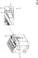
- the electronic relay 100 may be installed on board a switching device SW ( figure 2 ).
- the electronic relay 100 may be installed on board an electrical switchboard for electric power distribution grids.
- the electronic relay 100 may be a self-standing device installed on an electric power distribution grid.
- the electronic relay 100 is provided with a user-interface panel 110 (normally a front panel) including one or more user-interface components 101, 102, 103, 104.
- the above-mentioned user-interface components are configured to allow a user to interact with the electronic relay 100 (more particularly with the internal control unit thereof), in particular to provide input information or commands to the electronic relay and receive output information or visual signals from the electronic relay.
- the user interface components of the front panel 110 may include electromechanical switches or buttons, signalling devices, displays, and the like.
- the user-interface panel 110 conveniently includes user-interface components 101, 102 providing signalling functionalities. These signalling components are, in fact, configured to emit light signals indicative of the operating conditions (e.g. an electric fault or an operating state) of the electronic relay and/or the operating conditions of the electric or electronic devices operatively associated to the electronic relay.
- the operating conditions e.g. an electric fault or an operating state
- the light signals emitted by these user-interface components 101, 102 are formed by light pulses having a predefined colour and blinking at a predefined frequency.
- a light signal may be formed by a sequence of light pulses having a red colour and a blinking frequency of 2 Hz.
- each light signal emitted by a signalling component 101, 102 is associated to a predefined signalling content to be provided by the electronic relay.
- a light signal having a given colour and a given blinking frequency may be indicative of an electric fault
- another light signal having a different colour and/or a different blinking frequency may be indicative of an operating status of a switching device, and so on).
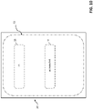
- Figure 2 shows an example of electronic relay, in which the user-interface panel 110 includes a number of light sources 101 (e.g. LED devices) adapted to emit the above-mentioned light signals.
- the above-mentioned signalling components are formed by the above-mentioned light sources 101.
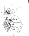
- Figure 3 shows another example of electronic relay, in which the user-interface panel 110 includes a display 114 configured to show signalling components 102 (e.g. graphic icons or signs shown on the display 114 and generated by means of a suitable graphic user-interface or hard lighting buttons) emitting the above-mentioned light signals.
- signalling components 102 e.g. graphic icons or signs shown on the display 114 and generated by means of a suitable graphic user-interface or hard lighting buttons
- the user-interface panel 110 conveniently includes also user-interface components 103, 104 providing set-up or control functionalities. These set-up or control components are configured to allow a user to provide input information or commands to the electronic relay.
- Figure 2 shows an example of electronic relay, in which the user-interface panel 110 includes a number of DIP switches and hard buttons 103 that can be manually operated by a user to provide set-up signals or command signals to the electronic relay.
- the DIP-switches and hard buttons 103 form the above-mentioned set-up or control components.
- the display 114 of the user-interface panel 110 may be configured to include control components 104 (e.g. graphic buttons shown on the display 114 and generated by means of a suitable graphic user-interface or hard control buttons) that can be touched by the user to provide command signals or information to the electronic relay.
- the electronic relay 100 comprises input and output ports 111, at which it can exchange data signals or control signals with external electric or electronic devices (e.g. sensors, other relays, switching devices, controllers, and the like) operatively connected thereto ( figure 1 ).
- the electronic relay 100 comprises also a controller 112 provided with processing resources (e.g. including one or more microprocessors) capable of executing software instructions stored or storable in a storage medium (e.g. a memory of said control unit) to carry out the functionalities provided for the electronic relay.
- processing resources e.g. including one or more microprocessors
- a storage medium e.g. a memory of said control unit
- control unit is operatively coupled with the user-interface components of the user-interface panel 110 and with the above-mentioned input and output ports 111.
- the electronic relay 100 may comprise or be operatively coupled with a number of accessory devices (not shown) designed to potentiate/expand the functionalities of the internal controller 112.
- the electronic relay 100 may comprise or be operatively coupled with various types of communication buses (not shown). As an example, the electronic relay 100 may be arranged to communicate with its accessory devices through local buses (e.g. implementing communication protocols of the Fieldbus type) and/or arranged to communicate with external devices through system or switchboard buses (e.g. implementing communication protocols of the Fieldbus, Modbus, Profibus, Profinet or Modbus-TCP type).
- local buses e.g. implementing communication protocols of the Fieldbus type
- system or switchboard buses e.g. implementing communication protocols of the Fieldbus, Modbus, Profibus, Profinet or Modbus-TCP type.
- the electronic relay 100 may also have remote communication capabilities for communication with one or more remote computerized devices through the Internet or suitable LAN or WAN communication lines.
- the electronic relay 100 may be realized at industrial level according to solutions of known type. Therefore, in the following, it will be described only in relation to the aspects of interest of the invention, for the sake of brevity.
- the method MTH is designed to assist a user in interacting with an electronic relay 100 for electric power distribution grids operating at low or medium voltage levels.
- a user "interacts with an electronic relay" when the user can provide input information or commands to the electronic relay and can receive output information or signals (e.g. the above-mentioned light signals) from the electronic relay.
- output information or signals e.g. the above-mentioned light signals
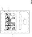
- the method MTH is designed for being implemented by a mobile computerised device 1, through which the user has to frame the front panel 110 of the electronic relay 100 ( figure 4 ).
- the mobile computerised device 1 may be of known type, such as a laptop computer, a tablet, a smartphone, or the like. As an example, it may be a commercially available smartphone equipped with an Android TM or iOS TM or Harmony TM operating system.
- the mobile computerised device 1 comprises a control unit 10 including digital data processing resources 10A (e.g. one or more microprocessors).
- the digital data processing resources 10A of the control unit 10 are capable of executing suitable software instructions stored in a memory, which are configured to implement the method MTH, according to the invention, when executed by said digital data processing resources ( figure 1 ).
- the above-mentioned software instructions are stored in a memory of the control unit 10 upon being downloaded (during a suitable installation phase or even in real time) into the mobile computerised device 1 from a suitable computerised platform, according to operating modes of known type.
- the mobile computerised device 1 comprises a display 20 and a camera 30 operatively associated to the control unit 10 and controlled by this latter in a known manner.
- the user of the computerised device has to frame the front panel 110 of the electronic relay 110. Images of the electronic relay are acquired through the camera 30 and shown by the control unit 10 on the display 20 ( figure 4 ). In order to capture the images of the electronic relay, data sampling techniques and/or signal processing techniques of known type may be used.
- the method MTH of the invention may be executed by the mobile computerised device 1 upon activation of the user, for example by touching a suitable activation icon made available on the display 20, when the above-mentioned software instructions are downloaded into the mobile computerised device 1.
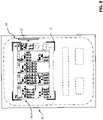
- control unit 10 of the mobile computerised device provides a graphic user interface 50 on the display 20, during the execution of the method MTH of the invention ( figure 5 ).
- the graphic user interface (GUI) 50 is a graphic environment that makes available suitable graphic patterns (e.g. graphic icons, graphic windows, graphic cursors, visual indicators, visual menus, augmented reality features, and the like) configured to allow a user to interact with the mobile computerised device 1.
- suitable graphic patterns e.g. graphic icons, graphic windows, graphic cursors, visual indicators, visual menus, augmented reality features, and the like
- the GUI 50 makes available graphic patterns to allow a user to provide input information or commands to the control unit 10 and to allow a user to read output information provided by the control unit 10 and, possibly, to observe visual signals to be observed by the user on the display 20.
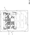
- Figure 5 shows the display 20 of the mobile computerised device during the execution of a generic step of the method MTH of the invention and it provides an overview of the functionalities provided by the GUI 50 of the mobile computerised device.
- the GUI 50 of the mobile computerised device is capable of making available graphic patterns 11 (e.g. graphic buttons) activatable by a user (e.g. by touching them on the display 20) to provide input commands to the control unit 10, graphic patters 12 (e.g. graphic windows, menus, masks and the like) to assist a user in providing input text information (e.g. by typing said information in the display 20) to the control unit 10 of the mobile computerised device, graphic patterns 13 (e.g. graphic windows, menus, masks and the like) to assist a user in reading output text information provided by the control unit 10, graphic patterns 14 (e.g. graphic buttons) activatable by a user (e.g. by touching them on the display 20) to navigate through different graphic pages or menus made available by the GUI 50 and augmented reality features 15, 16, 17 superimposed to an image IM framed by the camera 30 and shown on the display 30.
- graphic patterns 11 e.g. graphic buttons
- graphic patters 12 e.g. graphic windows, menus, masks and the
- the GUI 50 of the mobile computerised device may be designed according to computer graphics techniques of known type and the control unit 10 of the mobile computerised device may exploit data processing algorithms procedures or algorithms of known type to show the above-mentioned graphic patterns on the display 20 through the GUI 50.
- the method MTH comprises a step, in which the control unit 10 activates the camera 30 of the mobile computerised device 1.
- the activation of the camera 30 is carried out by the control unit 10 upon receiving a suitable input command by the user.
- a user may provide such an input command by touching a suitable graphic button 11 on a graphic page made available by the GUI 50 as soon as the execution of the method MTH starts ( figure 6 ).
- the method MTH comprises a step, in which the control unit 10 shows in real time (e.g. with a negligible time delay) images IM of the user-interface panel 110 on the display 20 of the mobile computerised device ( figure 7 ).
- the images IM are the images captured by the camera 30 while the user frames the user-interface 110 panel by means of the mobile computerised device 1.
- control unit 10 may adopt data processing techniques of known type to process the images captured by the camera 30, e.g. exploiting data processing procedures or algorithms commonly adopted in computerised devices (e.g. smartphones) equipped with a camera and provided with image preview capabilities.
- the GUI 50 makes available suitable graphic patterns 11, 13 to allow a user to provide commands or read information while the images IM captured by the camera 30 are shown on the display 20.
- the method MTH comprises a step, in which the control unit 10 processes the images IM captured by the camera 30 to identify the user-interface components and other physical features (e.g. corners, holes, edges, and the like) arranged on the user-interface panel 110.
- the control unit 10 processes the images IM captured by the camera 30 to identify the user-interface components and other physical features (e.g. corners, holes, edges, and the like) arranged on the user-interface panel 110.
- control unit 10 conveniently compares the images IM captured by the camera 30 with predefined models of user-interface panels of electronic relays of known type. To this aim, the control unit 10 may conveniently process the images IM captured by the camera 30 through data processing procedures or algorithms of known type, for example Viola-Jones object detection algorithm or Sliding Window algorithm, and the like.
- control unit 10 carries out automatically the above-mentioned identification step while the images IM captured by the camera 30 are shown on the display 20, as illustrated above ( figure 7 ).
- the method MTH comprises a step, in which the control unit 10 shows first augmented reality (AR) features 15 on the display 20 of the mobile computerised device ( figure 8 ).
- AR augmented reality
- the first AR features 15 are configured to assist a user in framing the user-interface panel 110 correctly by using the mobile computerised device (namely the camera 30 of this latter).
- the first augmented features 15 are designed to assist the user in finding the correct position and distance to frame the user-interface panel 110.
- control unit 10 shows the first AR features 15 superimposed to the images IM captured by the camera 30 and shown on the display 20.
- a user can easily watch some visual references useful to maintain the mobile computerised device 1 at a right position and distance with respect to the electronic relay 1 in order to frame correctly the user-interface panel 110.
- the control unit 10 generates the first AR features 15 basing on the identification information collected at the above-mentioned identification step of the user-interface components and physical features of the user-interface panel 110.
- the identified user-interface components and physical features of the user-interface panel 110 constitute, in fact, suitable character markers or positional tracers for generating the first AR features 15.
- control unit 10 may conveniently process the images captured by the camera 30 through suitable AR algorithms or procedures of known type, for example OpenGL's Scene Rendering Techniques, and the like.
- the method MTH comprises a step, in which the control unit 10 select and sample image portions IMR of the images IM of the user-interface panel 110, which are captured by the camera 30 during an observation time interval, in which the user frames said user-interface panel by means of the mobile computerised device ( figure 9 ).
- the control unit 10 carries out this sampling step upon receiving suitable input commands by the user, e.g. by activating suitable graphic patterns 11 made available by the GUI 50. In this way, for example, the user might easily control the duration of the above-mentioned observation time interval.
- control unit 10 may carry out this sampling step in an automatic manner upon the execution of the preceding steps illustrated above.
- the above-mentioned observation time interval might have a predefined duration.
- control unit 10 selects and sample the image portions IMR basing on the identification information collected at the above-mentioned identification step of the user-interface components and physical features of the user-interface panel 110.
- control unit 10 will select and sample the image portions IMR in which user-interface components 101 capable of emitting light signals are present.
- the sampled image portions IMR are stored in a suitable memory, conveniently of volatile type.
- the method MTH comprises a step, in which the control unit 10 processes the sampled image portions to identify possible light signals L emitted by one or more user-interface components 101 of the user-interface panel 110.
- control unit 10 detects the sequences of light pulses emitted by the user-interface components 101, e.g. by detecting the colour and the blinking frequency of said light pulses.
- control unit 10 compares the detected sequences of light pulses with predefined sequences of light pulses that can be emitted by the user-interface components of the electronic relay 100 (which have already been identified as described above).
- the above-mentioned predefined sequences of light pulses are conveniently stored in a memory and they are retrieved by the control unit 10 basing on the above-mentioned identification information collected at the above-mentioned identification step of the user-interface components and physical features of the user-interface panel 110.
- control unit 10 may conveniently process the sampled images IMR captured by the camera 30 through data processing procedures or algorithms of known type, for example neural networks with Yolo algorithm, and the like.
- control unit 10 carries out this identification step in real time, i.e. while the image portions IMR are sampled. In this way, when the above-mentioned observation period stops, the control unit 10 can immediately exploit the collected identification information of the emitted light signals L.
- control unit 10 may carry out the identification of the light signals L, at the end of the above-mentioned observation period.
- the method MTH comprises a step, in which the control unit 10, basing on the above-mentioned identification information of the light signals L, shows first information I1 on the display 20, which describes the light signals L emitted by the user-interface components 101 during the above-mentioned observation period.
- the GUI 50 makes available a page showing a graphic pattern 13 (e.g. a graphic box) reporting identification information on the identified light signals L.
- a graphic pattern 13 e.g. a graphic box
- the user can immediately understand the signalling content provided by the light signals L emitted by the electronic relay 100 ( figure 10 ).
- the GUI 50 makes available also a graphic pattern 11, which can be activated by a user to access (e.g. through a HTLM link) to one or more text pages describing the identified light signals L in more details.
- a graphic pattern 11 which can be activated by a user to access (e.g. through a HTLM link) to one or more text pages describing the identified light signals L in more details.
- the above-mentioned identification steps of the light signals L are particularly suitable for being carried out when the light signals L are emitted light sources 101 (e.g. LED devices) of the user-interface panel 110 (embodiment of figure 2 of the electronic relay).
- the light signals L are emitted light sources 101 (e.g. LED devices) of the user-interface panel 110 (embodiment of figure 2 of the electronic relay).
- these identification steps of the light signals L may be effectively carried out even if the light signals L are emitted by lighting icons or signs 102 shown on a display 114 of the user-interface panel 110 (embodiment of figure 3 of the electronic relay).
- the method MTH is designed to include some additional steps directed to improve the interaction of the user with the electronic relay 100 by using the mobile computerised device 1.
- the method MTH of the invention comprises a step, in which the control unit 10 shows second AR features 16 on the display 20 of the mobile computerised device ( figure 5 ).
- the second AR features 16 are configured to assist a user in identifying one or more user-interface components of the user-interface panel 110.
- the above-mentioned second augmented features 16 may be designed (e.g. in the form of arrows as shown in figure 5 ) to assist the user in finding the position of a given user-interface component of the user-interface panel 110, which is selected by the user.
- the above-mentioned second augmented features 16 may be designed (e.g. in the form of text boxes) to provide the user with information related to a given user-interface component of the user-interface panel 110, which is selected by the user.
- the control unit 10 shows the second AR features 16 superimposed to the images IM captured by the camera 30 and shown on the display 20. In this way, a user can easily identify a user-interface component of interest on the display 20 while framing the user-interface panel 110 of the electronic relay.
- control unit 10 shows the above-mentioned second AR feature 16 in response to receiving suitable input commands by the user.
- the GUI 50 makes available a graphic menu or a similar graphic pattern 11 on the display 20 through which a user may select a user interface component of interest.
- the GUI 50 may allow a user to select a given user-interface component of interest by directly touching this component on the image IM shown on the display 20.
- the control unit 10 generates the second AR features 16 basing on the identification information collected at the above-mentioned identification step of the user-interface components and physical features of the user-interface panel 110.
- the identification of the user-interface components of the user-interface panel 110 is, in fact, necessary to show correctly the second augmented features 16 on the display 20.
- the method MTH of the invention comprises a step, in which the control unit 10 shows third AR features 17 on the display 20 of the mobile computerised device ( figure 11 ).
- the third AR features 17 are configured to assist a user in carrying out an operating procedure (e.g. a test procedure) on the electronic relay 100.
- an operating procedure e.g. a test procedure
- the above-mentioned third AR features 17 are configured (e.g. in form of arrows) to indicate sequentially, on a selected image of the user-interface panel 110 shown on the display 20 of the mobile computerised device, the user-interface components to be operated in order to carry out the steps of above-mentioned test procedure.
- such an image of the user-predefined panel 110 is an image (fixed) captured by the control unit 10 ( figure 11 ) and stored in a memory.
- a user is not obliged to frame the electronic relay 100 during the execution of the above-mentioned procedure.
- control unit 10 shows also second information 12 describing the operating steps of the operating procedure to be carried out by the user.
- the GUI 50 makes available suitable text boxes 13 sequentially reporting the above-mentioned information I2 for the steps of the operating procedure to be carried out ( figure 11 ).
- GUI 50 preferably makes available suitable navigation buttons 14 to allow the user to navigate sequentially between the steps of the operating procedure to be carried out ( figure 11 ).
- control unit 10 shows the third augmented features 17 and the text information I2 to assist the user in interacting with the electronic relay.
- the user may thus use the mobile computerised device 1 as a tutorial tool to carry out the operating procedure of interest.
- control unit 10 carries out the above-illustrated steps of the method of the invention upon receiving suitable input commands by the user.
- a user may select an operating procedure of interest by activating a suitable graphic menu 11 made available by the GUI 50 on the display 20 ( figure 11 ).
- the method according to the invention, provides relevant advantages with respect to the state of the art.
- the method of the invention allows interacting easily and efficiently with an electronic relay in an assisted manner, through simple steps that can be carried out through a mobile computerised device 1 also by personnel having small experience or relatively low skills.
- the method of the invention allows a user to distinguish one from another the light signals L emitted by the signalling components of the user-interface panel of an electronic relay and to understand correctly the signalling information provided by said light signals.
- the method of the invention greatly facilitates the identification of the various user-interface components of the user-interface panel of an electronic relay as well as the execution of operating procedures (e.g. test procedures) to be carried out on the electronic relay.
- the method of the invention allows a user to interact easily with an electronic relay also in environments characterised by poor lighting conditions.
- the method of the invention does not require powerful processing resources for being executed. It can thus be executed by mobile computerised devices commonly available on the market.
Abstract
Description
- The present invention relates to the field of electric power distribution grids operating at low or medium voltage levels.
- More particularly, the present invention relates to a computer-implemented method to assist a user in interacting with an electronic relay for electric power distribution grids.
- Electric power distribution grids comprise switching devices (e.g. circuit breakers, disconnectors, contactors) or electronic devices (e.g. HMIs, PLCs, controllers and the like) designed to enable specific grid sections to operate properly.
- In many cases, these switching devices or electronic devices are operatively associated with or include electronic relays. These latter electronic devices are adapted to provide grid management functionalities (e.g. protection functionalities, synchro-reclosing functionalities, and the like) for grid sections.
- Normally, an electronic relay has a user-interface panel including a number of user-interface components (e.g. DIP switches, LED devices, and the like) designed to allow a user to interact with said electronic relay, namely to provide input information or commands to the electronic relay and receive output information or visual signals from the electronic relay.
- As is known, some user-interface components are designed for signalling purposes. To this aim, they can emit light signals indicative of operating conditions (e.g. an electric fault or a particular operating state) of the electronic relay and/or of the electric or electronic devices operatively associated to the electronic relay.
- Generally, these signalling components are light sources (e.g. LED devices) arranged on the user-interface panel of the electronic relay and driven by the controller of the electronic relay. However, in some cases, such user-interface components may include a display arranged on the user-interface panel and adapted to show signs or icons emitting light signals.
- In general, the light signals emitted by these user-interface components correspond to predefined signalling contents to be provided by the electronic relay. Therefore, a user can acquire information on the operating conditions of the electronic relay and/or the electric or electronic devices operatively associated thereto by simply observing the emitted light signals.
- The experience has shown that this task may be rather difficult when the user-interface panel is provided with multiple signalling components, each of which may be configured to emit light signals of different types.
- Therefore, unless being particularly experienced, a user has often to refer to technical manuals to distinguish the emitted light signals one from another and interpret correctly the information contents provided by said light signals.
- Obviously, this inconvenient makes the interaction with the electronic relay (e.g. during a maintenance intervention) rather inefficient and time consuming.
- In addition to the above, a user may encounter other difficulties in interacting with an electronic relay.
- Electronic relays often have user-interface panels with relatively complex layouts. Thus, a user may find difficulties in identifying the type or functionalities of the various user-interface components, in distinguishing the user-interface components one from another or in finding the position of a certain user-interface component of interest on the user-interface panel. Again, resorting to highly skilled personnel or to technical manuals is necessary to ensure a correct interaction with the electronic relay.
- The above-mentioned problems are even made more critical by the circumstance that, often, electronic relays are installed in positions uncomfortable to reach or in operating sites with poor lighting conditions and poor connectivity to the Internet.
- In view of the considerations above, it is evident that, in the state of the art, it is quite felt the need for innovative solutions of relatively easily technical implementation and capable of overcoming or mitigating the evidenced technical issues, thereby allowing a user (even if not specialized or particularly experienced) to interact with an electronic relay in an efficient and easy manner.
- In order to respond to this need, the present invention provides a computer-implemented method to assist a user in interacting with an electronic relay for electric power distribution grids, according to the following
claim 1 and the related dependent claims. - In a general definition, the method, according to the invention, comprises the following steps:
- activating a camera of a mobile computerised device;
- showing images of a user-interface panel of said electronic relay on a display of said mobile computerised device. Said images are conveniently captured by said camera while the user frames said user-interface panel by means of said mobile computerised device;
- processing said images to identify one or more user-interface components and other physical features of said user-interface panel. The identification of said user-interface components and physical features includes a comparison of said images with predefined models of user-interface panels;
- basing on the identification of the user-interface components and physical features of the user-interface panel, showing first augmented reality features on the display of the mobile computerised device. Said first augmented reality features are configured to assist a user in framing said user-interface panel by using the mobile computerised device. Said first augmented reality features are shown superimposed to said images on the display of the mobile computerised device;
- basing on the identification of the user-interface components and physical features of the user-interface panel, sampling portions of images of the user-interface panel of the electronic relay, which are captured by the camera of the mobile computerised device during an observation time interval, in which the user frames the user-interface panel of the electronic relay by means of said mobile computerised device;
- processing the sampled portions of images of the user-interface panel to identify one or more possible light signals emitted by one or more user-interface components of said user-interface panel. The identification of the light signals emitted by said user-interface components includes a detection of sequences of light pulses emitted by said user-interface components and a comparison of the detected sequences of light pulses with predefined sequences of light pulses that can be emitted by said user-interface components;
- basing on the identification of the light signals emitted by said user-interface components, showing on the display of the mobile computerised device first information describing the identified light signals emitted by said user-interface components.
- Preferably, the visual signals emitted by one or more user-interface components of the user-interface panel of the electronic relay are configured to signal an electric fault or an operating status of said electronic relay and/or of an electric or electronic device operatively associated to said electronic relay.
- Preferably the method of the invention comprises:
- basing on the identification of the user-interface components and physical features of the user-interface panel, showing, on the display of the mobile computerised device, second augmented reality features to assist a user in identifying said user-interface components. Said second augmented reality features are superimposed to the images shown on the display of the mobile computerised device.
- Preferably, the method of the invention comprises:
- showing, on the display of the mobile computerised device, third augmented reality features to assist a user in carrying out an operating procedure on said electronic relay. Said third augmented reality features are conveniently superimposed to a selected image of the user-interface panel of the electronic relay.
- Preferably, the method of the invention comprises:
- showing, on the display of the mobile computerised device, in addition to said third augmented reality features, second information describing the operating steps of the operating procedure to be carried out on the electronic relay.
- Preferably, the method of the invention comprises:
- providing a graphic user interface on the display of the mobile computerised device. Said graphic user interface includes graphic resources to show graphic patterns configured to allow a user to interact with said mobile computerised device.
- In some further aspects, the present invention thus relates to a mobile computerised device, according to the following
claim 10, and to a computer program, according to the followingclaim 11. - Further characteristics and advantages of the present invention will emerge more clearly from the description of preferred, but not exclusive embodiments, of which non-limiting examples are shown in the attached drawings, in which:
-
figure 1 schematically shows an example of electric grid including a switching device, an electronic relay operatively associated to said switching device and a mobile computerised device configured to implement the method of the invention; -
figure 2 schematically shows a switching device having an electronic relay installed on board a switching device; -
figure 3 schematically shows another example of front panel of an electronic relay; -
figure 4 schematically shows a mobile computerised device implementing the method of the invention; -
figures 5-11 are schematic views showing some steps of the method, according to the invention, as implemented by the mobile computerised device offigure 4 . - With reference to the above-mentioned figures, the present invention refers to a computer-implemented method MTH for assisting a user in interacting with an
electronic relay 100 for electric power distribution grids operating at low or medium voltage levels. - For the purposes of the present application, the term "low voltage" (LV) relates to operating voltages lower than 1 kV AC and 1.5 kV DC whereas the term "medium voltage" relates to operating voltages up to some tens of kV, e.g. up to 72 kV AC and 100 kV DC.
- The method, according to the invention, concerns the interaction of a user with an
electronic relay 100 adapted to be operatively associated to one or more electric devices (e.g. switching devices) or electronic devices (e.g. other electronic relays, HMIs, PLCs, controllers, and the like) of an electric grid. -
Figure 1 schematically shows an example ofelectric grid 500, in which anelectronic relay 100 is installed. In this case, theelectronic relay 100 is operatively associated with a corresponding switching device SW (e.g. a circuit breaker, disconnector, contactor, or the like) capable of electrically connecting or disconnectingdifferent grid sections 500A, 500B. - In general, the
electronic relay 100 is adapted to control the operation of the electric or electronic devices, to which it is operatively associated (e.g. the switching device SW) in such a way to provide grid management functionalities (e.g. control functionalities, protection functionalities, synchro-reclosing functionalities and the like) for some portions of the electric grid. - As an example, referring again to
figure 1 , theelectronic relay 100 may be adapted to enable the switching device SW to re-connect thegrid sections 500A, 500B only upon carrying out synchro-reclosing tasks confirming that these electric circuits operate within their compatibility area. - The
electronic relay 100 may be installed on board a switching device SW (figure 2 ). - As an alternative (not shown), the
electronic relay 100 may be installed on board an electrical switchboard for electric power distribution grids. - As a further alternative (not shown), the
electronic relay 100 may be a self-standing device installed on an electric power distribution grid. - The
electronic relay 100 is provided with a user-interface panel 110 (normally a front panel) including one or more user-interface components - In general, the above-mentioned user-interface components are configured to allow a user to interact with the electronic relay 100 (more particularly with the internal control unit thereof), in particular to provide input information or commands to the electronic relay and receive output information or visual signals from the electronic relay.
- The user interface components of the
front panel 110 may include electromechanical switches or buttons, signalling devices, displays, and the like. - The user-
interface panel 110 conveniently includes user-interface components - Preferably, the light signals emitted by these user-
interface components - In general, each light signal emitted by a
signalling component -
Figure 2 shows an example of electronic relay, in which the user-interface panel 110 includes a number of light sources 101 (e.g. LED devices) adapted to emit the above-mentioned light signals. In this case, the above-mentioned signalling components are formed by the above-mentionedlight sources 101. -
Figure 3 shows another example of electronic relay, in which the user-interface panel 110 includes adisplay 114 configured to show signalling components 102 (e.g. graphic icons or signs shown on thedisplay 114 and generated by means of a suitable graphic user-interface or hard lighting buttons) emitting the above-mentioned light signals. - The user-
interface panel 110 conveniently includes also user-interface components -
Figure 2 shows an example of electronic relay, in which the user-interface panel 110 includes a number of DIP switches andhard buttons 103 that can be manually operated by a user to provide set-up signals or command signals to the electronic relay. In this case, the DIP-switches andhard buttons 103 form the above-mentioned set-up or control components. - In the embodiment of
figure 3 , instead, thedisplay 114 of the user-interface panel 110 may be configured to include control components 104 (e.g. graphic buttons shown on thedisplay 114 and generated by means of a suitable graphic user-interface or hard control buttons) that can be touched by the user to provide command signals or information to the electronic relay. Preferably, theelectronic relay 100 comprises input andoutput ports 111, at which it can exchange data signals or control signals with external electric or electronic devices (e.g. sensors, other relays, switching devices, controllers, and the like) operatively connected thereto (figure 1 ). - Preferably, the
electronic relay 100 comprises also acontroller 112 provided with processing resources (e.g. including one or more microprocessors) capable of executing software instructions stored or storable in a storage medium (e.g. a memory of said control unit) to carry out the functionalities provided for the electronic relay. - Conveniently, the above-mentioned control unit is operatively coupled with the user-interface components of the user-
interface panel 110 and with the above-mentioned input andoutput ports 111. - In some cases, the
electronic relay 100 may comprise or be operatively coupled with a number of accessory devices (not shown) designed to potentiate/expand the functionalities of theinternal controller 112. - The
electronic relay 100 may comprise or be operatively coupled with various types of communication buses (not shown). As an example, theelectronic relay 100 may be arranged to communicate with its accessory devices through local buses (e.g. implementing communication protocols of the Fieldbus type) and/or arranged to communicate with external devices through system or switchboard buses (e.g. implementing communication protocols of the Fieldbus, Modbus, Profibus, Profinet or Modbus-TCP type). - The
electronic relay 100 may also have remote communication capabilities for communication with one or more remote computerized devices through the Internet or suitable LAN or WAN communication lines. - In general, the
electronic relay 100 may be realized at industrial level according to solutions of known type. Therefore, in the following, it will be described only in relation to the aspects of interest of the invention, for the sake of brevity. - As mentioned above, the method MTH, according to the invention, is designed to assist a user in interacting with an
electronic relay 100 for electric power distribution grids operating at low or medium voltage levels. - For the sake of clarity, it is reiterated that a user "interacts with an electronic relay" when the user can provide input information or commands to the electronic relay and can receive output information or signals (e.g. the above-mentioned light signals) from the electronic relay.
- The method MTH, according to the invention, is designed for being implemented by a mobile
computerised device 1, through which the user has to frame thefront panel 110 of the electronic relay 100 (figure 4 ). - In general, the mobile
computerised device 1 may be of known type, such as a laptop computer, a tablet, a smartphone, or the like. As an example, it may be a commercially available smartphone equipped with an Android™ or iOS™ or Harmony™ operating system. The mobilecomputerised device 1 comprises acontrol unit 10 including digitaldata processing resources 10A (e.g. one or more microprocessors). - Conveniently, the digital
data processing resources 10A of thecontrol unit 10 are capable of executing suitable software instructions stored in a memory, which are configured to implement the method MTH, according to the invention, when executed by said digital data processing resources (figure 1 ). - Preferably, the above-mentioned software instructions are stored in a memory of the
control unit 10 upon being downloaded (during a suitable installation phase or even in real time) into the mobilecomputerised device 1 from a suitable computerised platform, according to operating modes of known type. - In order to allow the implementation of the method MTH, according to the invention, the mobile
computerised device 1 comprises adisplay 20 and acamera 30 operatively associated to thecontrol unit 10 and controlled by this latter in a known manner. - As mentioned above, in fact, during the execution of the method MTH, according to the invention, the user of the computerised device has to frame the
front panel 110 of theelectronic relay 110. Images of the electronic relay are acquired through thecamera 30 and shown by thecontrol unit 10 on the display 20 (figure 4 ). In order to capture the images of the electronic relay, data sampling techniques and/or signal processing techniques of known type may be used. - The steps of method MTH of the invention are now described in details referring to
figures 5-11 , in which thedisplay 20 of a mobilecomputerised device 1, during the execution of some steps of the method MTH, is schematically represented. - The steps of the method MTH of the invention will be here described with reference to the embodiment of
figure 2 of theelectronic relay 100 for the sake of simplicity. It is however intended that the method MTH of the invention can be carried out even if the front-panel 110 of theelectronic relay 100 is arranged differently, for example in such a way to include adisplay 114 as shown infigure 3 . - Conveniently, the method MTH of the invention may be executed by the mobile
computerised device 1 upon activation of the user, for example by touching a suitable activation icon made available on thedisplay 20, when the above-mentioned software instructions are downloaded into the mobilecomputerised device 1. - Preferably, the
control unit 10 of the mobile computerised device provides agraphic user interface 50 on thedisplay 20, during the execution of the method MTH of the invention (figure 5 ). - The graphic user interface (GUI) 50 is a graphic environment that makes available suitable graphic patterns (e.g. graphic icons, graphic windows, graphic cursors, visual indicators, visual menus, augmented reality features, and the like) configured to allow a user to interact with the mobile
computerised device 1. - In particular, the
GUI 50 makes available graphic patterns to allow a user to provide input information or commands to thecontrol unit 10 and to allow a user to read output information provided by thecontrol unit 10 and, possibly, to observe visual signals to be observed by the user on thedisplay 20. -
Figure 5 shows thedisplay 20 of the mobile computerised device during the execution of a generic step of the method MTH of the invention and it provides an overview of the functionalities provided by theGUI 50 of the mobile computerised device. - As illustrated, in general, during the execution of the method MTH, the
GUI 50 of the mobile computerised device is capable of making available graphic patterns 11 (e.g. graphic buttons) activatable by a user (e.g. by touching them on the display 20) to provide input commands to thecontrol unit 10, graphic patters 12 (e.g. graphic windows, menus, masks and the like) to assist a user in providing input text information (e.g. by typing said information in the display 20) to thecontrol unit 10 of the mobile computerised device, graphic patterns 13 (e.g. graphic windows, menus, masks and the like) to assist a user in reading output text information provided by thecontrol unit 10, graphic patterns 14 (e.g. graphic buttons) activatable by a user (e.g. by touching them on the display 20) to navigate through different graphic pages or menus made available by theGUI 50 and augmented reality features 15, 16, 17 superimposed to an image IM framed by thecamera 30 and shown on thedisplay 30. - In general, the
GUI 50 of the mobile computerised device may be designed according to computer graphics techniques of known type and thecontrol unit 10 of the mobile computerised device may exploit data processing algorithms procedures or algorithms of known type to show the above-mentioned graphic patterns on thedisplay 20 through theGUI 50. - According to the invention, the method MTH comprises a step, in which the
control unit 10 activates thecamera 30 of the mobilecomputerised device 1. - Preferably, the activation of the
camera 30 is carried out by thecontrol unit 10 upon receiving a suitable input command by the user. Conveniently, a user may provide such an input command by touching a suitablegraphic button 11 on a graphic page made available by theGUI 50 as soon as the execution of the method MTH starts (figure 6 ). - According to the invention, the method MTH comprises a step, in which the
control unit 10 shows in real time (e.g. with a negligible time delay) images IM of the user-interface panel 110 on thedisplay 20 of the mobile computerised device (figure 7 ). - The images IM are the images captured by the
camera 30 while the user frames the user-interface 110 panel by means of the mobilecomputerised device 1. - In order to show the images IM on the
display 20, thecontrol unit 10 may adopt data processing techniques of known type to process the images captured by thecamera 30, e.g. exploiting data processing procedures or algorithms commonly adopted in computerised devices (e.g. smartphones) equipped with a camera and provided with image preview capabilities. - Preferably, the
GUI 50 makes available suitablegraphic patterns camera 30 are shown on thedisplay 20. - According to the invention, the method MTH comprises a step, in which the
control unit 10 processes the images IM captured by thecamera 30 to identify the user-interface components and other physical features (e.g. corners, holes, edges, and the like) arranged on the user-interface panel 110. - In order to carry out this identification step, the
control unit 10 conveniently compares the images IM captured by thecamera 30 with predefined models of user-interface panels of electronic relays of known type. To this aim, thecontrol unit 10 may conveniently process the images IM captured by thecamera 30 through data processing procedures or algorithms of known type, for example Viola-Jones object detection algorithm or Sliding Window algorithm, and the like. - Preferably, the
control unit 10 carries out automatically the above-mentioned identification step while the images IM captured by thecamera 30 are shown on thedisplay 20, as illustrated above (figure 7 ). - According to the invention, the method MTH comprises a step, in which the
control unit 10 shows first augmented reality (AR) features 15 on thedisplay 20 of the mobile computerised device (figure 8 ). - The first AR features 15 are configured to assist a user in framing the user-
interface panel 110 correctly by using the mobile computerised device (namely thecamera 30 of this latter). For example, the firstaugmented features 15 are designed to assist the user in finding the correct position and distance to frame the user-interface panel 110. - Conveniently, the
control unit 10 shows the first AR features 15 superimposed to the images IM captured by thecamera 30 and shown on thedisplay 20. In this way, a user can easily watch some visual references useful to maintain the mobilecomputerised device 1 at a right position and distance with respect to theelectronic relay 1 in order to frame correctly the user-interface panel 110. - The
control unit 10 generates the first AR features 15 basing on the identification information collected at the above-mentioned identification step of the user-interface components and physical features of the user-interface panel 110. - The identified user-interface components and physical features of the user-
interface panel 110 constitute, in fact, suitable character markers or positional tracers for generating the first AR features 15. - In order to generate the AR features 15, the
control unit 10 may conveniently process the images captured by thecamera 30 through suitable AR algorithms or procedures of known type, for example OpenGL's Scene Rendering Techniques, and the like. - According to the invention, the method MTH comprises a step, in which the
control unit 10 select and sample image portions IMR of the images IM of the user-interface panel 110, which are captured by thecamera 30 during an observation time interval, in which the user frames said user-interface panel by means of the mobile computerised device (figure 9 ). Preferably, thecontrol unit 10 carries out this sampling step upon receiving suitable input commands by the user, e.g. by activating suitablegraphic patterns 11 made available by theGUI 50. In this way, for example, the user might easily control the duration of the above-mentioned observation time interval. - As an alternative, the
control unit 10 may carry out this sampling step in an automatic manner upon the execution of the preceding steps illustrated above. In this case, the above-mentioned observation time interval might have a predefined duration. - Conveniently, the
control unit 10 selects and sample the image portions IMR basing on the identification information collected at the above-mentioned identification step of the user-interface components and physical features of the user-interface panel 110. - In particular, the
control unit 10 will select and sample the image portions IMR in which user-interface components 101 capable of emitting light signals are present. - Preferably, the sampled image portions IMR are stored in a suitable memory, conveniently of volatile type.
- According to the invention, the method MTH comprises a step, in which the
control unit 10 processes the sampled image portions to identify possible light signals L emitted by one or more user-interface components 101 of the user-interface panel 110. - In order to carry out this identification step, the
control unit 10 detects the sequences of light pulses emitted by the user-interface components 101, e.g. by detecting the colour and the blinking frequency of said light pulses. - Subsequently, the
control unit 10 compares the detected sequences of light pulses with predefined sequences of light pulses that can be emitted by the user-interface components of the electronic relay 100 (which have already been identified as described above). - The above-mentioned predefined sequences of light pulses are conveniently stored in a memory and they are retrieved by the
control unit 10 basing on the above-mentioned identification information collected at the above-mentioned identification step of the user-interface components and physical features of the user-interface panel 110. - In order to identify the light signals L emitted by the user-interface components, the
control unit 10 may conveniently process the sampled images IMR captured by thecamera 30 through data processing procedures or algorithms of known type, for example neural networks with Yolo algorithm, and the like. - Preferably, the
control unit 10 carries out this identification step in real time, i.e. while the image portions IMR are sampled. In this way, when the above-mentioned observation period stops, thecontrol unit 10 can immediately exploit the collected identification information of the emitted light signals L. - As an alternative, the
control unit 10 may carry out the identification of the light signals L, at the end of the above-mentioned observation period. - According to the invention, the method MTH comprises a step, in which the
control unit 10, basing on the above-mentioned identification information of the light signals L, shows first information I1 on thedisplay 20, which describes the light signals L emitted by the user-interface components 101 during the above-mentioned observation period. - Preferably, the
GUI 50 makes available a page showing a graphic pattern 13 (e.g. a graphic box) reporting identification information on the identified light signals L. In this way, the user can immediately understand the signalling content provided by the light signals L emitted by the electronic relay 100 (figure 10 ). - Preferably, the
GUI 50 makes available also agraphic pattern 11, which can be activated by a user to access (e.g. through a HTLM link) to one or more text pages describing the identified light signals L in more details. - It is reiterated how the above-mentioned steps of identification of the light signals L emitted by the user-interface components of the user-
interface panel 110 can be carried out independently on the physical nature of these signalling components. - The above-mentioned identification steps of the light signals L are particularly suitable for being carried out when the light signals L are emitted light sources 101 (e.g. LED devices) of the user-interface panel 110 (embodiment of
figure 2 of the electronic relay). - However, these identification steps of the light signals L may be effectively carried out even if the light signals L are emitted by lighting icons or
signs 102 shown on adisplay 114 of the user-interface panel 110 (embodiment offigure 3 of the electronic relay). - Preferably, the method MTH is designed to include some additional steps directed to improve the interaction of the user with the
electronic relay 100 by using the mobilecomputerised device 1. - According to some embodiments of the invention, the method MTH of the invention comprises a step, in which the
control unit 10 shows second AR features 16 on thedisplay 20 of the mobile computerised device (figure 5 ). - The second AR features 16 are configured to assist a user in identifying one or more user-interface components of the user-
interface panel 110. - For example, the above-mentioned second augmented features 16 may be designed (e.g. in the form of arrows as shown in
figure 5 ) to assist the user in finding the position of a given user-interface component of the user-interface panel 110, which is selected by the user. - As another example, the above-mentioned second augmented features 16 may be designed (e.g. in the form of text boxes) to provide the user with information related to a given user-interface component of the user-
interface panel 110, which is selected by the user. Conveniently, thecontrol unit 10 shows the second AR features 16 superimposed to the images IM captured by thecamera 30 and shown on thedisplay 20. In this way, a user can easily identify a user-interface component of interest on thedisplay 20 while framing the user-interface panel 110 of the electronic relay. - Preferably, the
control unit 10 shows the above-mentionedsecond AR feature 16 in response to receiving suitable input commands by the user. - Preferably, the
GUI 50 makes available a graphic menu or a similargraphic pattern 11 on thedisplay 20 through which a user may select a user interface component of interest. - As an alternative, the
GUI 50 may allow a user to select a given user-interface component of interest by directly touching this component on the image IM shown on thedisplay 20. - The
control unit 10 generates the second AR features 16 basing on the identification information collected at the above-mentioned identification step of the user-interface components and physical features of the user-interface panel 110. The identification of the user-interface components of the user-interface panel 110 is, in fact, necessary to show correctly the secondaugmented features 16 on thedisplay 20. - According to some embodiments of the invention, the method MTH of the invention comprises a step, in which the
control unit 10 shows third AR features 17 on thedisplay 20 of the mobile computerised device (figure 11 ). - The third AR features 17 are configured to assist a user in carrying out an operating procedure (e.g. a test procedure) on the
electronic relay 100. - Conveniently, the above-mentioned third AR features 17 are configured (e.g. in form of arrows) to indicate sequentially, on a selected image of the user-
interface panel 110 shown on thedisplay 20 of the mobile computerised device, the user-interface components to be operated in order to carry out the steps of above-mentioned test procedure. - Preferably, such an image of the user-
predefined panel 110 is an image (fixed) captured by the control unit 10 (figure 11 ) and stored in a memory. In this way, in fact, a user is not obliged to frame theelectronic relay 100 during the execution of the above-mentioned procedure. - Preferably, in addition to the above-mentioned third augmented reality features, the
control unit 10 shows alsosecond information 12 describing the operating steps of the operating procedure to be carried out by the user. - Conveniently, in addition to the image of the user-
interface panel 110, theGUI 50 makes availablesuitable text boxes 13 sequentially reporting the above-mentioned information I2 for the steps of the operating procedure to be carried out (figure 11 ). - In addition to the above, the
GUI 50 preferably makes availablesuitable navigation buttons 14 to allow the user to navigate sequentially between the steps of the operating procedure to be carried out (figure 11 ). - The above-mentioned steps of the method are particularly useful to improve the efficiency in operating the
electronic relay 100. - At each step of the operating procedure to be carried out, the
control unit 10 shows the thirdaugmented features 17 and the text information I2 to assist the user in interacting with the electronic relay. The user may thus use the mobilecomputerised device 1 as a tutorial tool to carry out the operating procedure of interest. - Preferably, the
control unit 10 carries out the above-illustrated steps of the method of the invention upon receiving suitable input commands by the user. A user may select an operating procedure of interest by activating a suitablegraphic menu 11 made available by theGUI 50 on the display 20 (figure 11 ). - The method, according to the invention, provides relevant advantages with respect to the state of the art.
- The method of the invention allows interacting easily and efficiently with an electronic relay in an assisted manner, through simple steps that can be carried out through a mobile
computerised device 1 also by personnel having small experience or relatively low skills. The method of the invention allows a user to distinguish one from another the light signals L emitted by the signalling components of the user-interface panel of an electronic relay and to understand correctly the signalling information provided by said light signals. - The method of the invention greatly facilitates the identification of the various user-interface components of the user-interface panel of an electronic relay as well as the execution of operating procedures (e.g. test procedures) to be carried out on the electronic relay.
- Thanks to the use of a mobile computerised device, the method of the invention allows a user to interact easily with an electronic relay also in environments characterised by poor lighting conditions.
- The method of the invention does not require powerful processing resources for being executed. It can thus be executed by mobile computerised devices commonly available on the market.
- It is important to notice that the method of the invention can be carried out by a mobile computerised device in absence of Internet connectivity. This characteristic is particularly useful to facilitate the interaction with electronic relays installed in remote operating sites, in which the on-line consultation of technical manuals by the user would be quite difficult for obvious reasons.
Claims (11)
- A method (MTH) for assisting a user in interacting with an electronic relay (100) for electric power distribution grids, said electronic relay having a user-interface panel (110) including one or more user-interface components (101, 102, 103) configured to allow a user to interact with said electronic relay, characterised in that said method comprises:- activating a camera (30) of a mobile computerised device (1);- showing images (IM) of said user-interface panel (110) on a display (20) of said mobile computerised device, said images being captured by said camera (30) while the user frames said user-interface panel by means of said mobile computerised device;- processing said images (IM) to identify said user-interface components (101, 102, 103, 104) and other physical features of said user-interface panel, the identification of said user-interface components and physical features including a comparison of said images with predefined models of user-interface panels;- basing on the identification of said user-interface components and physical features, showing first augmented reality features (15) on said display (20), said first augmented reality features being configured to assist a user in framing said user-interface panel (110) by using said mobile computerised device, said first augmented reality features being shown superimposed to said images (IM) on said display;- basing on the identification of the user-interface components and physical features of the user-interface panel, sampling one or more image portions (IMR) of said user-interface panel (110) captured during an observation time interval, in which the user frames said user-interface panel (110) by means of said mobile computerised device;- processing the sampled image portions (IMR) of said user-interface panel (110) to identify one or more light signals (L) emitted by one or more user-interface components (101) of said user-interface panel, the identification of said light signals including a detection of sequences of light pulses emitted by said user-interface components and a comparison of the detected sequences of light pulses with predefined sequences of light pulses that can be emitted by said user-interface components;- basing on the identification of said light signals, showing on said display (20) first information (11) describing the identified light signals emitted by said user-interface components (101).
- Method, according to claim 1, characterised in that said light signals (L) are configured to signal an electric fault or an operating status of said electronic relay (100) or of an electric or electronic device operatively associated to said electronic relay.
- Method, according to one or more of the previous claims, characterised in that it comprises:- basing on the identification of said user-interface components and physical features, showing, on said display (20), second augmented reality features (16) to assist a user in identifying said user-interface components (101, 102, 103, 104), said second augmented reality features being superimposed to said images (IM).
- Method, according to one or more of the previous claims, characterised in that it comprises:- showing, on said display (20), third augmented reality features (17) to assist a user in carrying out an operating procedure on said electronic relay, said third augmented reality features being superimposed to a selected image (IM) of the user-interface panel (110) of said electronic relay (100);
- Method, according to claim 4, characterised in that it comprises:- showing, on said display (20), in addition to said third augmented reality features (17), second information (12) describing the operating steps of said operating procedure to be carried out by the user.
- Method, according to one or more of the previous claims, characterised in it comprises:- providing a graphic user interface (50) on said display (20), said graphic user interface including graphic resources to show graphic patterns (11, 12, 13, 14) configured to allow a user to interact with said mobile computerised device.
- Method, according to one or more of the previous claims, characterised in that said electronic relay is installed on board a switching device (SW) for electric power distribution grids.
- Method, according to one or more of the claims from 1 to 6, characterised in that said electronic relay is installed on an electric switchboard for electric power distribution grids.
- Method, according to one or more of the claims from 1 to 6, characterised in that said electronic relay is a self-standing device installed in an electric power distribution grid.
- A mobile computerised device (1) comprising a display (20), a camera (30) and a control unit (10) operatively associated to said display and said camera characterised in that said control unit (10) comprises data processing resources (10A) capable of executing software instructions stored in a memory, said software instructions being configured to implement a method (MTH), according to one or more of the previous claims, when executed by said data processing resources.
- A computer program stored in a memory characterised in that it comprises software instructions executable by data processing resources (10A), said software instructions being configured to implement a method (MTH), according to one or more of the claims from 1 to 9, when executed by said data processing resources.
Priority Applications (3)
| Application Number | Priority Date | Filing Date | Title |
|---|---|---|---|
| EP21152722.1A EP4033397A1 (en) | 2021-01-21 | 2021-01-21 | A computer-implemented method for assisting a user in interacting with an electronic relay for electric power distribution grids |
| CN202210060303.7A CN114816160A (en) | 2021-01-21 | 2022-01-19 | Computer-implemented method for assisting user interaction with electronic relays of a power distribution network |
| US17/580,915 US11961292B2 (en) | 2021-01-21 | 2022-01-21 | Computer-implemented method for assisting a user in interacting with an electronic relay for electric power distribution grids |
Applications Claiming Priority (1)
| Application Number | Priority Date | Filing Date | Title |
|---|---|---|---|
| EP21152722.1A EP4033397A1 (en) | 2021-01-21 | 2021-01-21 | A computer-implemented method for assisting a user in interacting with an electronic relay for electric power distribution grids |
Publications (1)
| Publication Number | Publication Date |
|---|---|
| EP4033397A1 true EP4033397A1 (en) | 2022-07-27 |
Family
ID=74194674
Family Applications (1)
| Application Number | Title | Priority Date | Filing Date |
|---|---|---|---|
| EP21152722.1A Pending EP4033397A1 (en) | 2021-01-21 | 2021-01-21 | A computer-implemented method for assisting a user in interacting with an electronic relay for electric power distribution grids |
Country Status (3)
| Country | Link |
|---|---|
| US (1) | US11961292B2 (en) |
| EP (1) | EP4033397A1 (en) |
| CN (1) | CN114816160A (en) |
Citations (5)
| Publication number | Priority date | Publication date | Assignee | Title |
|---|---|---|---|---|
| US20070236366A1 (en) * | 2004-07-25 | 2007-10-11 | Joshua Gur | Method and system for the acquisition of data and for the display of data |
| US20120259973A1 (en) * | 2011-04-07 | 2012-10-11 | International Business Machines Corporation | Systems and methods for managing computing systems utilizing augmented reality |
| US10116861B1 (en) * | 2017-05-01 | 2018-10-30 | Ricoh Company, Ltd. | Guided image capture user interface |
| EP3678048A1 (en) * | 2017-09-30 | 2020-07-08 | Schneider Electric Industries SAS | Method and device for identifying state of electrical apparatus |
| US20200302172A1 (en) * | 2019-03-18 | 2020-09-24 | Fuji Xerox Co., Ltd. | Information processing apparatus, information processing system, and non-transitory computer readable medium storing program |
Family Cites Families (5)
| Publication number | Priority date | Publication date | Assignee | Title |
|---|---|---|---|---|
| CN103324943A (en) | 2013-06-18 | 2013-09-25 | 中国人民解放军第二炮兵工程大学 | Identification method of complex device panel image multi-sub zone state |
| CN105894015B (en) | 2016-03-28 | 2019-08-20 | 国网浙江省电力公司宁波供电公司 | A kind of banister state analysis method and system |
| CN105825204A (en) | 2016-04-08 | 2016-08-03 | 国家电网公司 | Method for identifying power equipment meter at night through intelligent camera |
| CN106355187A (en) | 2016-09-07 | 2017-01-25 | 西华大学 | Application of visual information to electrical equipment monitoring |
| ES2881504T3 (en) * | 2017-04-04 | 2021-11-29 | Abb Spa | A computer-implemented method of setting up an electronic relay |
-
2021
- 2021-01-21 EP EP21152722.1A patent/EP4033397A1/en active Pending
-
2022
- 2022-01-19 CN CN202210060303.7A patent/CN114816160A/en active Pending
- 2022-01-21 US US17/580,915 patent/US11961292B2/en active Active
Patent Citations (5)
| Publication number | Priority date | Publication date | Assignee | Title |
|---|---|---|---|---|
| US20070236366A1 (en) * | 2004-07-25 | 2007-10-11 | Joshua Gur | Method and system for the acquisition of data and for the display of data |
| US20120259973A1 (en) * | 2011-04-07 | 2012-10-11 | International Business Machines Corporation | Systems and methods for managing computing systems utilizing augmented reality |
| US10116861B1 (en) * | 2017-05-01 | 2018-10-30 | Ricoh Company, Ltd. | Guided image capture user interface |
| EP3678048A1 (en) * | 2017-09-30 | 2020-07-08 | Schneider Electric Industries SAS | Method and device for identifying state of electrical apparatus |
| US20200302172A1 (en) * | 2019-03-18 | 2020-09-24 | Fuji Xerox Co., Ltd. | Information processing apparatus, information processing system, and non-transitory computer readable medium storing program |
Non-Patent Citations (1)
| Title |
|---|
| G. DINI ET AL: "Application of Augmented Reality Techniques in Through-life Engineering Services", PROCEDIA CIRP, vol. 38, 1 January 2015 (2015-01-01), NL, pages 14 - 23, XP055649710, ISSN: 2212-8271, DOI: 10.1016/j.procir.2015.07.044 * |
Also Published As
| Publication number | Publication date |
|---|---|
| US11961292B2 (en) | 2024-04-16 |
| US20220230433A1 (en) | 2022-07-21 |
| CN114816160A (en) | 2022-07-29 |
Similar Documents
| Publication | Publication Date | Title |
|---|---|---|
| US8249836B2 (en) | Simulation system for FACTS connected online to SCADA system | |
| EP2653941B1 (en) | Field devices sending icon configuration data to workstations | |
| US20050021291A1 (en) | Networked control system with real time monitoring | |
| US10846348B2 (en) | Computerized system for managing the operation of an electric power distribution grid with a configurable accessory device | |
| EP3385828B1 (en) | A computer-implemented method for configuring an electronic relay | |
| US20170083017A1 (en) | Ladder diagram monitoring device capable of additionally displaying operation situation of cnc in comment | |
| EP2887122A1 (en) | Smart eyewear device for electronic or electrical applications | |
| JP2010072924A (en) | Surveillance simulation apparatus | |
| EP4033397A1 (en) | A computer-implemented method for assisting a user in interacting with an electronic relay for electric power distribution grids | |
| CN103026306B (en) | For method and the configuration computing machine of configuration energy automation equipment | |
| US20210089192A1 (en) | Writing code of devices from a control computer by calling development tool from a semantic zoom enhanced user interface | |
| US20060149397A1 (en) | Method, device and system for displaying data of a machine control system | |
| JPH09245076A (en) | Wiring board designing device | |
| EP3318936A1 (en) | A computer-implemented method for configuring electronic relays in an electric power distribution grid | |
| JP2016174496A (en) | System diagram automatic creation system | |
| JP4032491B2 (en) | Supervisory control system | |
| JP2006311763A (en) | Control system for monitoring electric system | |
| CN211044205U (en) | Mouse and keyboard simulator | |
| US8082500B2 (en) | Method and apparatus for communicating with an intelligent electronic device associated to a switching device in power systems | |
| CN115693639A (en) | Switching control method, device, equipment and storage medium | |
| KR20220130918A (en) | Method and Apparatus for Matching of Diagnostic Item in On-line Diagnosis System of Electric Power Facility | |
| JP2000047962A (en) | Remote controller | |
| JP2022044510A (en) | Substation monitoring control system | |
| CN115104289A (en) | Terminal monitoring device | |
| JP2003157105A (en) | Control system, and its program and recording medium |
Legal Events
| Date | Code | Title | Description |
|---|---|---|---|
| PUAI | Public reference made under article 153(3) epc to a published international application that has entered the european phase |
Free format text: ORIGINAL CODE: 0009012 |
|
| STAA | Information on the status of an ep patent application or granted ep patent |
Free format text: STATUS: THE APPLICATION HAS BEEN PUBLISHED |
|
| AK | Designated contracting states |
Kind code of ref document: A1 Designated state(s): AL AT BE BG CH CY CZ DE DK EE ES FI FR GB GR HR HU IE IS IT LI LT LU LV MC MK MT NL NO PL PT RO RS SE SI SK SM TR |
|
| STAA | Information on the status of an ep patent application or granted ep patent |
Free format text: STATUS: REQUEST FOR EXAMINATION WAS MADE |
|
| 17P | Request for examination filed |
Effective date: 20230118 |
|
| RBV | Designated contracting states (corrected) |
Designated state(s): AL AT BE BG CH CY CZ DE DK EE ES FI FR GB GR HR HU IE IS IT LI LT LU LV MC MK MT NL NO PL PT RO RS SE SI SK SM TR |
|
| STAA | Information on the status of an ep patent application or granted ep patent |
Free format text: STATUS: EXAMINATION IS IN PROGRESS |
|
| 17Q | First examination report despatched |
Effective date: 20231207 |