EP4033287B1 - Ophthalimic lens with optimized extended depth of focus - Google Patents
Ophthalimic lens with optimized extended depth of focus Download PDFInfo
- Publication number
- EP4033287B1 EP4033287B1 EP20217905.7A EP20217905A EP4033287B1 EP 4033287 B1 EP4033287 B1 EP 4033287B1 EP 20217905 A EP20217905 A EP 20217905A EP 4033287 B1 EP4033287 B1 EP 4033287B1
- Authority
- EP
- European Patent Office
- Prior art keywords
- lens
- pattern
- profile
- tfmtf
- focus
- Prior art date
- Legal status (The legal status is an assumption and is not a legal conclusion. Google has not performed a legal analysis and makes no representation as to the accuracy of the status listed.)
- Active
Links
Images



Classifications
-
- G—PHYSICS
- G02—OPTICS
- G02C—SPECTACLES; SUNGLASSES OR GOGGLES INSOFAR AS THEY HAVE THE SAME FEATURES AS SPECTACLES; CONTACT LENSES
- G02C7/00—Optical parts
- G02C7/02—Lenses; Lens systems ; Methods of designing lenses
- G02C7/022—Ophthalmic lenses having special refractive features achieved by special materials or material structures
-
- A—HUMAN NECESSITIES
- A61—MEDICAL OR VETERINARY SCIENCE; HYGIENE
- A61F—FILTERS IMPLANTABLE INTO BLOOD VESSELS; PROSTHESES; DEVICES PROVIDING PATENCY TO, OR PREVENTING COLLAPSING OF, TUBULAR STRUCTURES OF THE BODY, e.g. STENTS; ORTHOPAEDIC, NURSING OR CONTRACEPTIVE DEVICES; FOMENTATION; TREATMENT OR PROTECTION OF EYES OR EARS; BANDAGES, DRESSINGS OR ABSORBENT PADS; FIRST-AID KITS
- A61F2/00—Filters implantable into blood vessels; Prostheses, i.e. artificial substitutes or replacements for parts of the body; Appliances for connecting them with the body; Devices providing patency to, or preventing collapsing of, tubular structures of the body, e.g. stents
- A61F2/02—Prostheses implantable into the body
- A61F2/14—Eye parts, e.g. lenses or corneal implants; Artificial eyes
- A61F2/16—Intraocular lenses
-
- A—HUMAN NECESSITIES
- A61—MEDICAL OR VETERINARY SCIENCE; HYGIENE
- A61F—FILTERS IMPLANTABLE INTO BLOOD VESSELS; PROSTHESES; DEVICES PROVIDING PATENCY TO, OR PREVENTING COLLAPSING OF, TUBULAR STRUCTURES OF THE BODY, e.g. STENTS; ORTHOPAEDIC, NURSING OR CONTRACEPTIVE DEVICES; FOMENTATION; TREATMENT OR PROTECTION OF EYES OR EARS; BANDAGES, DRESSINGS OR ABSORBENT PADS; FIRST-AID KITS
- A61F2/00—Filters implantable into blood vessels; Prostheses, i.e. artificial substitutes or replacements for parts of the body; Appliances for connecting them with the body; Devices providing patency to, or preventing collapsing of, tubular structures of the body, e.g. stents
- A61F2/02—Prostheses implantable into the body
- A61F2/14—Eye parts, e.g. lenses or corneal implants; Artificial eyes
- A61F2/16—Intraocular lenses
- A61F2/1613—Intraocular lenses having special lens configurations, e.g. multipart lenses; having particular optical properties, e.g. pseudo-accommodative lenses, lenses having aberration corrections, diffractive lenses, lenses for variably absorbing electromagnetic radiation, lenses having variable focus
- A61F2/1648—Multipart lenses
-
- B—PERFORMING OPERATIONS; TRANSPORTING
- B82—NANOTECHNOLOGY
- B82Y—SPECIFIC USES OR APPLICATIONS OF NANOSTRUCTURES; MEASUREMENT OR ANALYSIS OF NANOSTRUCTURES; MANUFACTURE OR TREATMENT OF NANOSTRUCTURES
- B82Y20/00—Nanooptics, e.g. quantum optics or photonic crystals
-
- G—PHYSICS
- G02—OPTICS
- G02B—OPTICAL ELEMENTS, SYSTEMS OR APPARATUS
- G02B27/00—Optical systems or apparatus not provided for by any of the groups G02B1/00 - G02B26/00, G02B30/00
- G02B27/0025—Optical systems or apparatus not provided for by any of the groups G02B1/00 - G02B26/00, G02B30/00 for optical correction, e.g. distorsion, aberration
-
- G—PHYSICS
- G02—OPTICS
- G02B—OPTICAL ELEMENTS, SYSTEMS OR APPARATUS
- G02B27/00—Optical systems or apparatus not provided for by any of the groups G02B1/00 - G02B26/00, G02B30/00
- G02B27/0025—Optical systems or apparatus not provided for by any of the groups G02B1/00 - G02B26/00, G02B30/00 for optical correction, e.g. distorsion, aberration
- G02B27/0037—Optical systems or apparatus not provided for by any of the groups G02B1/00 - G02B26/00, G02B30/00 for optical correction, e.g. distorsion, aberration with diffracting elements
-
- G—PHYSICS
- G02—OPTICS
- G02B—OPTICAL ELEMENTS, SYSTEMS OR APPARATUS
- G02B27/00—Optical systems or apparatus not provided for by any of the groups G02B1/00 - G02B26/00, G02B30/00
- G02B27/0075—Optical systems or apparatus not provided for by any of the groups G02B1/00 - G02B26/00, G02B30/00 with means for altering, e.g. increasing, the depth of field or depth of focus
-
- G—PHYSICS
- G02—OPTICS
- G02B—OPTICAL ELEMENTS, SYSTEMS OR APPARATUS
- G02B27/00—Optical systems or apparatus not provided for by any of the groups G02B1/00 - G02B26/00, G02B30/00
- G02B27/42—Diffraction optics, i.e. systems including a diffractive element being designed for providing a diffractive effect
- G02B27/4205—Diffraction optics, i.e. systems including a diffractive element being designed for providing a diffractive effect having a diffractive optical element [DOE] contributing to image formation, e.g. whereby modulation transfer function MTF or optical aberrations are relevant
-
- G—PHYSICS
- G02—OPTICS
- G02B—OPTICAL ELEMENTS, SYSTEMS OR APPARATUS
- G02B27/00—Optical systems or apparatus not provided for by any of the groups G02B1/00 - G02B26/00, G02B30/00
- G02B27/42—Diffraction optics, i.e. systems including a diffractive element being designed for providing a diffractive effect
- G02B27/4205—Diffraction optics, i.e. systems including a diffractive element being designed for providing a diffractive effect having a diffractive optical element [DOE] contributing to image formation, e.g. whereby modulation transfer function MTF or optical aberrations are relevant
- G02B27/4211—Diffraction optics, i.e. systems including a diffractive element being designed for providing a diffractive effect having a diffractive optical element [DOE] contributing to image formation, e.g. whereby modulation transfer function MTF or optical aberrations are relevant correcting chromatic aberrations
-
- G—PHYSICS
- G02—OPTICS
- G02B—OPTICAL ELEMENTS, SYSTEMS OR APPARATUS
- G02B3/00—Simple or compound lenses
- G02B3/0081—Simple or compound lenses having one or more elements with analytic function to create variable power
-
- G—PHYSICS
- G02—OPTICS
- G02B—OPTICAL ELEMENTS, SYSTEMS OR APPARATUS
- G02B5/00—Optical elements other than lenses
- G02B5/18—Diffraction gratings
-
- G—PHYSICS
- G02—OPTICS
- G02B—OPTICAL ELEMENTS, SYSTEMS OR APPARATUS
- G02B5/00—Optical elements other than lenses
- G02B5/18—Diffraction gratings
- G02B5/1828—Diffraction gratings having means for producing variable diffraction
-
- G—PHYSICS
- G02—OPTICS
- G02B—OPTICAL ELEMENTS, SYSTEMS OR APPARATUS
- G02B5/00—Optical elements other than lenses
- G02B5/18—Diffraction gratings
- G02B5/1876—Diffractive Fresnel lenses; Zone plates; Kinoforms
- G02B5/189—Structurally combined with optical elements not having diffractive power
- G02B5/1895—Structurally combined with optical elements not having diffractive power such optical elements having dioptric power
-
- G—PHYSICS
- G02—OPTICS
- G02C—SPECTACLES; SUNGLASSES OR GOGGLES INSOFAR AS THEY HAVE THE SAME FEATURES AS SPECTACLES; CONTACT LENSES
- G02C7/00—Optical parts
- G02C7/02—Lenses; Lens systems ; Methods of designing lenses
- G02C7/04—Contact lenses for the eyes
-
- G—PHYSICS
- G02—OPTICS
- G02C—SPECTACLES; SUNGLASSES OR GOGGLES INSOFAR AS THEY HAVE THE SAME FEATURES AS SPECTACLES; CONTACT LENSES
- G02C7/00—Optical parts
- G02C7/02—Lenses; Lens systems ; Methods of designing lenses
- G02C7/04—Contact lenses for the eyes
- G02C7/049—Contact lenses having special fitting or structural features achieved by special materials or material structures
-
- G—PHYSICS
- G02—OPTICS
- G02C—SPECTACLES; SUNGLASSES OR GOGGLES INSOFAR AS THEY HAVE THE SAME FEATURES AS SPECTACLES; CONTACT LENSES
- G02C7/00—Optical parts
- G02C7/02—Lenses; Lens systems ; Methods of designing lenses
- G02C7/06—Lenses; Lens systems ; Methods of designing lenses bifocal; multifocal ; progressive
-
- A—HUMAN NECESSITIES
- A61—MEDICAL OR VETERINARY SCIENCE; HYGIENE
- A61F—FILTERS IMPLANTABLE INTO BLOOD VESSELS; PROSTHESES; DEVICES PROVIDING PATENCY TO, OR PREVENTING COLLAPSING OF, TUBULAR STRUCTURES OF THE BODY, e.g. STENTS; ORTHOPAEDIC, NURSING OR CONTRACEPTIVE DEVICES; FOMENTATION; TREATMENT OR PROTECTION OF EYES OR EARS; BANDAGES, DRESSINGS OR ABSORBENT PADS; FIRST-AID KITS
- A61F2/00—Filters implantable into blood vessels; Prostheses, i.e. artificial substitutes or replacements for parts of the body; Appliances for connecting them with the body; Devices providing patency to, or preventing collapsing of, tubular structures of the body, e.g. stents
- A61F2/02—Prostheses implantable into the body
- A61F2/14—Eye parts, e.g. lenses or corneal implants; Artificial eyes
- A61F2/16—Intraocular lenses
- A61F2/1613—Intraocular lenses having special lens configurations, e.g. multipart lenses; having particular optical properties, e.g. pseudo-accommodative lenses, lenses having aberration corrections, diffractive lenses, lenses for variably absorbing electromagnetic radiation, lenses having variable focus
-
- G—PHYSICS
- G02—OPTICS
- G02B—OPTICAL ELEMENTS, SYSTEMS OR APPARATUS
- G02B3/00—Simple or compound lenses
-
- G—PHYSICS
- G02—OPTICS
- G02C—SPECTACLES; SUNGLASSES OR GOGGLES INSOFAR AS THEY HAVE THE SAME FEATURES AS SPECTACLES; CONTACT LENSES
- G02C2202/00—Generic optical aspects applicable to one or more of the subgroups of G02C7/00
- G02C2202/20—Diffractive and Fresnel lenses or lens portions
-
- G—PHYSICS
- G02—OPTICS
- G02C—SPECTACLES; SUNGLASSES OR GOGGLES INSOFAR AS THEY HAVE THE SAME FEATURES AS SPECTACLES; CONTACT LENSES
- G02C2202/00—Generic optical aspects applicable to one or more of the subgroups of G02C7/00
- G02C2202/22—Correction of higher order and chromatic aberrations, wave front measurement and calculation
-
- Y—GENERAL TAGGING OF NEW TECHNOLOGICAL DEVELOPMENTS; GENERAL TAGGING OF CROSS-SECTIONAL TECHNOLOGIES SPANNING OVER SEVERAL SECTIONS OF THE IPC; TECHNICAL SUBJECTS COVERED BY FORMER USPC CROSS-REFERENCE ART COLLECTIONS [XRACs] AND DIGESTS
- Y10—TECHNICAL SUBJECTS COVERED BY FORMER USPC
- Y10S—TECHNICAL SUBJECTS COVERED BY FORMER USPC CROSS-REFERENCE ART COLLECTIONS [XRACs] AND DIGESTS
- Y10S977/00—Nanotechnology
- Y10S977/902—Specified use of nanostructure
-
- Y—GENERAL TAGGING OF NEW TECHNOLOGICAL DEVELOPMENTS; GENERAL TAGGING OF CROSS-SECTIONAL TECHNOLOGIES SPANNING OVER SEVERAL SECTIONS OF THE IPC; TECHNICAL SUBJECTS COVERED BY FORMER USPC CROSS-REFERENCE ART COLLECTIONS [XRACs] AND DIGESTS
- Y10—TECHNICAL SUBJECTS COVERED BY FORMER USPC
- Y10S—TECHNICAL SUBJECTS COVERED BY FORMER USPC CROSS-REFERENCE ART COLLECTIONS [XRACs] AND DIGESTS
- Y10S977/00—Nanotechnology
- Y10S977/902—Specified use of nanostructure
- Y10S977/932—Specified use of nanostructure for electronic or optoelectronic application
Definitions
- This invention relates to an ophthalmic lens for imaging with extended depth of focus.
- the present invention solves the above need by providing a novel coding mechanism for coding a light field in the vicinity of an imaging lens unit.
- the present invention takes advantage of the earlier technique developed by the inventors and disclosed for example in the above-indicated patent publications US 7,365,917 , US 7,061,693 , WO 07/141788 .
- Imaging systems such as human eye, have a depth of focus (DOF) determined by a number of physical parameters - F/#, illumination spectrum and the aberrations terms (deviations from ideal imaging).
- DOF depth of focus
- EDOF technology utilizes phase-only coding (e.g. phase mask), having large spatial features (i.e. low spatial frequency phase transitions), located in the imaging system entrance pupil/aperture plane/exit pupil in order to extend the DOF without reducing the aperture, i.e. causing neither loss of energy, nor loss of resolution.
- phase-only coding e.g. phase mask
- large spatial features i.e. low spatial frequency phase transitions
- This technique eliminates a need for any image processing in order to restore the image.
- Phase coding of the effective aperture of an imaging lens unit for extending the depth of focus of the lens unit results in a total profile of Through Focus Modulation Transfer Function (TFMTF) different from that of the imaging lens unit with no phase coding.
- TFMTF profile defined by the EDOF-based phase coded imaging lens unit can be further optimized to obtain such a TFMTF profile, in which the TFMTF plot components corresponding to the desirably extended depth of focus for different wavelengths overlap in the optimal way.
- the optimization comprises applying additional coding to the light field in the vicinity of the phase coded effective aperture of the imaging lens unit selected to take into account the EDOF effect to be obtained by the phase coding within the imaging lens unit, e.g.
- the LCA cause a shift in the extended focal position for different wavelengths, and could thus smear the performance of the EDOF equipped imaging system.
- the invention provides for compensating for LCA effect while extending the depth of focusing of the imaging lens unit.
- the invention utilizes a dispersion profile coding (chromatic aberrations correction) of the light field which has been or is to be phase coded to thereby provide imaging with the desired profile of extended depth of focus for multiple wavelengths where the wavelengths' TFMTF profiles are desirably overlapping within the EDOF profile.
- the term "compensating for LCA" as used herein means reducing LCA for a lens relative to the same lens exclusive of the dispersion profile coding.
- FIG. 1A and 1B illustrating dispersion occurring in an imaging lens unit utilizing EDOF phase coding.
- Fig. 1A shows the simulation results for a Through Focus Modulation Transfer Function (TFMTF) for 100cyc/mm spatial frequency.
- TFMTF Through Focus Modulation Transfer Function
- G 1 -G 4 corresponding to four different wavelengths in the range 0.5 - 0.6 ⁇ m.
- This simulation was carried out with Zemax, using "Arizona Eye model”. As shown, there is a relative shift for each wavelength: the plot for wavelength 0.6 ⁇ m is shifted 0.18mm away from the corresponding graph for wavelength of 0.5 ⁇ m.
- the actual obtainable depth of focus i.e. providing sufficient contract of the image
- the optimal way of overlapping means overlap within the required depth of focus region(s), defined by the specific applications. This may be one continuous region as for example required in ophthalmic applications, or dual- or multi-region depth of focus for example for imagers requiring improved image quality in the near and far vision zones.
- the required compensation should take into account that DOF extensions for different wavelengths are different, i.e. larger for longer wavelength and smaller for shorter one, and also the initial depth of focus requirements with respect to a specific imaging lens unit.
- the chromatic aberrations correction should be configured in accordance with the depth of focus profiles, of the imaging lens with the EDOF effect, for the multiple wavelengths, e.g. those of the primary colors.
- the present invention solves the above problem by providing an all-optical processor to be applied to a light field incident onto a predetermined imaging lens unit (e.g. passing through the lens unit).
- This optical processor is formed by passing light through a pattern of spaced apart regions of different optical properties.
- This pattern defines a phase coder affecting TFMTF profiles for different wavelength components in accordance with predetermined EDOF profiles for certain imaging lens unit, and also defines a dispersion profile coder configured to provide a predetermined overlapping between the TFMTF profiles within the EDOF profile.
- the imaging arrangement 10 includes an imaging lens unit 12 and an optical processor 14.
- the imaging lens unit 12 may include one or more optical elements configured and operable to create an image of an object in an imaging plane.
- the optical processor 14 may be a separate unit located close to (up to physical contact with) the imaging lens unit 12 (generally located so as to be in the vicinity of the effective aperture of the lens unit) located at either sides of the lens unit or both of them; or may be at least partially incorporated within the lens unit (embedded therein).
- the optical processor is configured to provide a desired profile of the extended depth of focus for the given imaging lens unit and a desired TFMTF profiles of multiple wavelengths within said profile of the extended depth of focus.
- the optical processor 14 includes a phase coder (mask) 16 defined by a first pattern PC and a dispersion profile coder 18 (e.g. mask) defined by a second pattern DC.
- the masks 16 and 18 are shown as being separate elements both separated from the lens unit, the phase coding mask 16 being located upstream of the lens unit and the dispersion coding mask 18 being located downstream of the lens with respect to the light propagation direction.
- the lens 12 and the coders 16, 18 may be arranged differently.
- the codes of masks 16 and 18 may be integrated in a single pattern (mask) being separated from the lens or being integral therewith (e.g. embedded therein).
- the imaging arrangement 10 is configured with one or more optical powers, to provide predetermined extension profile for the focus (focii) defined by said optical power, and to have a desired chromatic dispersion profile.
- the phase coder is configured to provide said predetermined extension profile, while substantially not adding any optical power to the lens unit.
- the desired optical power of the entire imaging arrangement for each wavelength is a sum of the respective optical powers of the elements of such arrangement.
- the dispersion coder is thus configured with a certain optical power (for each wavelength) selected such that the dispersion coder provides desirable shifts of the TFMTFs within the predetermined depth of focus extension profile.
- desired TFMTFs may be multi-lobe functions. Accordingly, for the given imaging lens with EDOF assembly, different dispersion codings might be used in order to achieve the desired overlap between different wavelength lobes.
- Fig. 2B illustrates schematically an imaging arrangement 100 according to an example of the invention.
- the imaging arrangement 100 includes an imaging lens unit 12 (formed by a single lens in the present example), and an optical processor 14 which is carried by opposite sides 12A and 12B of the lens unit.
- the phase and dispersion coders are implemented as surface patterns on the lens unit rear and front surfaces 12A and 12B.
- One of these patterns or both may be in the form of a surface relief; or may be formed by spaced-apart regions of a material having refractive index different from that of the lens.
- Figs. 3A-3C exemplifying the effect of the optical processor according to the light field coding technique of the invention.
- Fig. 3A exemplifies a radial profile of the EDOF phase coding pattern PC (mask), which is a phase only, substantially not diffractive pattern designed to provide a desired EDOF profile for said imaging lens unit.
- Fig. 3B exemplifies a radial profile of the dispersion profile coding pattern DC, which is a diffractive pattern designed in accordance with the imaging lens with the EDOF profile to desirably shift the EDOF components of different wavelengths within said desired profile.
- Fig. 3C shows a combined coding (pattern) applied to the light field propagating in the imaging lens arrangement.
- chromatic aberrations corrector configured for properly shifting the EDOF TFMTF plots
- a diffractive element e.g. Fresnel lens
- Fig. 4A shows that application of the appropriately designed diffraction pattern to the EDOF imaging lens provides that the TFMTFs for multiple wavelength are well co-aligned (generally desirably overlap), giving a desired total TFMTF. The latter is shown in Fig. 4B .
- the diffractive lens is configured for ophthalmic application considering the optical power of the eye lens.
- Lenses as described herein can be embodied as any suitable ophthalmic lens.
- ophthalmic lens refers to an artificial lens for use with the eye. Preferred ophthalmic lenses are made of biomedical materials suitable for contact with eye tissue.
- ophthalmic lens includes but is not limited to intraocular lenses (IOLs), contact lenses, and corneal onlays or inlays.
- Non-optical components may be added in some embodiments of ophthalmic lenses (e.g., in intraocular lenses, one or more haptics may be added).
- Lenses according to aspects of the present invention can comprise combinations of surfaces having any suitable shape (plano, convex, concave).
- the illustrated embodiments of lenses have only one zone; however, other embodiments may have multiple zones, the zones having different optical powers.
- the lenses may be embodied as intraocular lenses adapted to provide accommodative movement.
- a lens according to aspects of the present invention can be used in a dual element accommodative lens as described in U.S. Patent No. 6,488,708 issued December 4, 2002, to Sarfarazi , or a single element accommodative lens as described in U.S. Patent No. 5,674,282, issued September 7, 1997, to Cumming .
- a pattern may be placed on a surface of the lens by various techniques known in the art.
- the pattern may be lathe cut, lased or etched directly into the lens surface.
- the pattern may be provided on a mold having a molding surface for forming the lens surface, wherein the pattern is transferred to the mold during casting of the lens.
- a conventional manner of making contact lenses involves casting a mixture of lens-forming monomers in a two-part plastic mold.
- One mold part includes a molding surface for forming the front lens surface
- the second mold part includes a molding surface for forming the back lens surface.
- the monomer mixture is polymerized, or cured, while in the two-part mold to form a contact lens.
- the plastic mold parts are injected molded from a metal tool.
- the pattern may be provided on the metal tools, such as by lathing, and thus transferred to the contact lens surface during the casting process.
Landscapes
- Physics & Mathematics (AREA)
- Health & Medical Sciences (AREA)
- Optics & Photonics (AREA)
- General Physics & Mathematics (AREA)
- Ophthalmology & Optometry (AREA)
- General Health & Medical Sciences (AREA)
- Engineering & Computer Science (AREA)
- Life Sciences & Earth Sciences (AREA)
- Chemical & Material Sciences (AREA)
- Nanotechnology (AREA)
- Heart & Thoracic Surgery (AREA)
- Vascular Medicine (AREA)
- Transplantation (AREA)
- Animal Behavior & Ethology (AREA)
- Oral & Maxillofacial Surgery (AREA)
- Public Health (AREA)
- Veterinary Medicine (AREA)
- Biomedical Technology (AREA)
- Cardiology (AREA)
- Biophysics (AREA)
- Crystallography & Structural Chemistry (AREA)
- Eyeglasses (AREA)
- Lenses (AREA)
- Diffracting Gratings Or Hologram Optical Elements (AREA)
- Prostheses (AREA)
Description
- This application claims the benefit under 35 USC 119(e) of
U.S. Provisional Application No. 61/302,588, filed on February 9, 2010 - This invention relates to an ophthalmic lens for imaging with extended depth of focus.
- Extension of the depth of focus of imaging is a common goal of various imaging systems. Techniques for extending the depth of focus of imaging systems have been developed, and are described for example in the following publications:
-
US 6,536,898 andUS 7,025,454 disclose extended depth of field optics for human eye. This technique utilizes modification of contact lenses, intraocular implants, and/or the surface of the eye itself. This is accomplished by applying selected phase variations to these optical elements (e.g., by varying surface thickness of the cornea of the eye). The phase variations EDF-code the wavefront and cause the optical transfer function to remain essentially constant within a range of distances from the in-focus position. This provides a coded image on the retina. The human brain decodes this coded image, resulting in an in-focus image over an increased depth of field. -
US 2009/0279189 describes a lens having extended depth of focus. The lens includes a plurality of lens layers, each lens layer being axi-symmetric and having an extended depth of focus to focus light in a corresponding section of a focal curve in the form of a straight line located on an optical axis. In the optical system, light is focused on an optical axis to obtain a clear image in a wide distance range between a camera and an object. The optical system has a point spread function that is simpler and more symmetric. That is, the optical system provides improved continuity of a lens surface and easiness and flexibility in optical designing. -
US 7,365,917 ,US 7,061,693 ,WO 07/141788 - An ophthalmic lens according to the present invention is defined in appended
claim 1. Embodiments of the claimed invention are defined in the dependent claims. - There is a need in the art in a novel all-optical technique, which provides for appropriately extended depth of focus (EDOF) of an imaging lens unit.
- The present invention solves the above need by providing a novel coding mechanism for coding a light field in the vicinity of an imaging lens unit. The present invention takes advantage of the earlier technique developed by the inventors and disclosed for example in the above-indicated patent publications
US 7,365,917 ,US 7,061,693 ,WO 07/141788 - The main idea of the present invention is based on the understanding of the following: Imaging systems, such as human eye, have a depth of focus (DOF) determined by a number of physical parameters - F/#, illumination spectrum and the aberrations terms (deviations from ideal imaging). For aberration-free system, the DOF could be defined as follows (using Rayleigh 1/4 wave rule of thumb):

- Therefore, in order to extend the DOF of such an imaging system, the aperture of the imaging system is usually reduced, unavoidably resulting in the lost of energy and resolution. EDOF technology, developed by the inventors, utilizes phase-only coding (e.g. phase mask), having large spatial features (i.e. low spatial frequency phase transitions), located in the imaging system entrance pupil/aperture plane/exit pupil in order to extend the DOF without reducing the aperture, i.e. causing neither loss of energy, nor loss of resolution. This technique eliminates a need for any image processing in order to restore the image.
- Phase coding of the effective aperture of an imaging lens unit for extending the depth of focus of the lens unit results in a total profile of Through Focus Modulation Transfer Function (TFMTF) different from that of the imaging lens unit with no phase coding. The inventors have found that such TFMTF profile defined by the EDOF-based phase coded imaging lens unit can be further optimized to obtain such a TFMTF profile, in which the TFMTF plot components corresponding to the desirably extended depth of focus for different wavelengths overlap in the optimal way. The optimization comprises applying additional coding to the light field in the vicinity of the phase coded effective aperture of the imaging lens unit selected to take into account the EDOF effect to be obtained by the phase coding within the imaging lens unit, e.g. continuous range EDOF or discrete multi-range EDOF, and to compensate for longitudinal chromatic aberrations (LCA) of such EDOF imaging lens unit. Further details of lenses providing phase coding are given in
U.S. Patent No. 7,061,693 issued on June 13, 2006 andU.S. Patent No. 7,365,917 issued on April 29, 2008 both to Zalevsky. Both of said patents are hereby incorporated by reference herein in their entirety. - The LCA cause a shift in the extended focal position for different wavelengths, and could thus smear the performance of the EDOF equipped imaging system. The invention provides for compensating for LCA effect while extending the depth of focusing of the imaging lens unit. To this end, the invention utilizes a dispersion profile coding (chromatic aberrations correction) of the light field which has been or is to be phase coded to thereby provide imaging with the desired profile of extended depth of focus for multiple wavelengths where the wavelengths' TFMTF profiles are desirably overlapping within the EDOF profile. The term "compensating for LCA" as used herein means reducing LCA for a lens relative to the same lens exclusive of the dispersion profile coding.
- In order to understand the invention and to see how it may be carried out in practice, embodiments will now be described, by way of non-limiting example only, with reference to the accompanying drawings, in which:
-
Figs. 1A and 1B illustrate dispersion effects in an imaging lens with EDOF; -
Fig. 2A shows schematically an imaging lens arrangement of the present invention; -
Fig. 2B shows a specific example of the implementation of the imaging arrangement ofFig. 2A ; -
Figs. 3A-3C exemplify the light field coding technique of the invention:Fig. 3A exemplifies an EDOF phase coding pattern,Fig. 3B exemplifies the dispersion profile coding pattern, andFig. 3C shows a combined coding (pattern) applied to the light field propagating in the imaging lens arrangement; and -
Figs. 4A and 4B show, respectively, the dispersion of the TFMTF profiles for different wavelengths and the total TFMTF, in the imaging lens arrangement of the present invention. - Reference is made to
Figs. 1A and 1B illustrating dispersion occurring in an imaging lens unit utilizing EDOF phase coding. -
Fig. 1A shows the simulation results for a Through Focus Modulation Transfer Function (TFMTF) for 100cyc/mm spatial frequency. Four graphs are shown, G1-G4 , corresponding to four different wavelengths in the range 0.5 - 0.6 µm. This simulation was carried out with Zemax, using "Arizona Eye model". As shown, there is a relative shift for each wavelength: the plot for wavelength 0.6µm is shifted 0.18mm away from the corresponding graph for wavelength of 0.5µm. - Assuming all wavelengths are weighted the same (are of the same intensity), the resulted plot is illustrated in
Fig. 1B . - Thus, for a given value of the TFMTF, the actual obtainable depth of focus (i.e. providing sufficient contract of the image) is smaller than that for each wavelength, e.g. for TFMTF=0.2, about 6mm focal depth is obtained for each wavelength (
Fig. 1A ), while being about 4mm for the total TFMTF plot (Fig. 1B ). - Hence, there is a need to compensate the dispersion such as to cause the TFMTF plots overlap in the optimal way. It should be understood that the optimal way of overlapping means overlap within the required depth of focus region(s), defined by the specific applications. This may be one continuous region as for example required in ophthalmic applications, or dual- or multi-region depth of focus for example for imagers requiring improved image quality in the near and far vision zones.
- The required compensation should take into account that DOF extensions for different wavelengths are different, i.e. larger for longer wavelength and smaller for shorter one, and also the initial depth of focus requirements with respect to a specific imaging lens unit. In other words, the chromatic aberrations correction (dispersion profile coding) should be configured in accordance with the depth of focus profiles, of the imaging lens with the EDOF effect, for the multiple wavelengths, e.g. those of the primary colors.
- The present invention solves the above problem by providing an all-optical processor to be applied to a light field incident onto a predetermined imaging lens unit (e.g. passing through the lens unit). This optical processor is formed by passing light through a pattern of spaced apart regions of different optical properties. This pattern defines a phase coder affecting TFMTF profiles for different wavelength components in accordance with predetermined EDOF profiles for certain imaging lens unit, and also defines a dispersion profile coder configured to provide a predetermined overlapping between the TFMTF profiles within the EDOF profile.
- Reference is made to
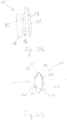
Fig. 2A showing schematically animaging arrangement 10 of the present invention. Theimaging arrangement 10 includes animaging lens unit 12 and an optical processor 14. Theimaging lens unit 12 may include one or more optical elements configured and operable to create an image of an object in an imaging plane. The optical processor 14 may be a separate unit located close to (up to physical contact with) the imaging lens unit 12 (generally located so as to be in the vicinity of the effective aperture of the lens unit) located at either sides of the lens unit or both of them; or may be at least partially incorporated within the lens unit (embedded therein). The optical processor is configured to provide a desired profile of the extended depth of focus for the given imaging lens unit and a desired TFMTF profiles of multiple wavelengths within said profile of the extended depth of focus. As shown inFig. 2A , the optical processor 14 includes a phase coder (mask) 16 defined by a first pattern PC and a dispersion profile coder 18 (e.g. mask) defined by a second pattern DC. In this example, themasks phase coding mask 16 being located upstream of the lens unit and thedispersion coding mask 18 being located downstream of the lens with respect to the light propagation direction. It should however be noted that for the purposes of the invention thelens 12 and thecoders masks - It should be understood that the
imaging arrangement 10 is configured with one or more optical powers, to provide predetermined extension profile for the focus (focii) defined by said optical power, and to have a desired chromatic dispersion profile. The phase coder is configured to provide said predetermined extension profile, while substantially not adding any optical power to the lens unit. The desired optical power of the entire imaging arrangement for each wavelength is a sum of the respective optical powers of the elements of such arrangement. The dispersion coder is thus configured with a certain optical power (for each wavelength) selected such that the dispersion coder provides desirable shifts of the TFMTFs within the predetermined depth of focus extension profile. It should be understood that desired TFMTFs may be multi-lobe functions. Accordingly, for the given imaging lens with EDOF assembly, different dispersion codings might be used in order to achieve the desired overlap between different wavelength lobes. -
Fig. 2B illustrates schematically an imaging arrangement 100 according to an example of the invention. The same reference numbers identify components common in all examples. The imaging arrangement 100 includes an imaging lens unit 12 (formed by a single lens in the present example), and an optical processor 14 which is carried byopposite sides 12A and 12B of the lens unit. Here, the phase and dispersion coders (patterns PC and DC) are implemented as surface patterns on the lens unit rear andfront surfaces 12A and 12B. One of these patterns or both may be in the form of a surface relief; or may be formed by spaced-apart regions of a material having refractive index different from that of the lens. - Reference is made to
Figs. 3A-3C exemplifying the effect of the optical processor according to the light field coding technique of the invention.Fig. 3A exemplifies a radial profile of the EDOF phase coding pattern PC (mask), which is a phase only, substantially not diffractive pattern designed to provide a desired EDOF profile for said imaging lens unit.Fig. 3B exemplifies a radial profile of the dispersion profile coding pattern DC, which is a diffractive pattern designed in accordance with the imaging lens with the EDOF profile to desirably shift the EDOF components of different wavelengths within said desired profile.Fig. 3C shows a combined coding (pattern) applied to the light field propagating in the imaging lens arrangement. - Let us consider the above coding of the imaging lens unit similar to that of the example of
Figs. 1A-1B . The function of the chromatic aberrations corrector (dispersion profile coder), configured for properly shifting the EDOF TFMTF plots, is implemented by a diffractive element (e.g. Fresnel lens). - Diffractive lens focal length, fDiff ; has the following wavelength dependency:


-
Fig. 4A shows that application of the appropriately designed diffraction pattern to the EDOF imaging lens provides that the TFMTFs for multiple wavelength are well co-aligned (generally desirably overlap), giving a desired total TFMTF. The latter is shown inFig. 4B . - The
diffractive lens 18 used for dispersion profile coding was simulated as made of PMMA material with total thickness, Tthick , determined as:

- Lenses as described herein can be embodied as any suitable ophthalmic lens. The term "ophthalmic lens" refers to an artificial lens for use with the eye. Preferred ophthalmic lenses are made of biomedical materials suitable for contact with eye tissue. The term "ophthalmic lens" includes but is not limited to intraocular lenses (IOLs), contact lenses, and corneal onlays or inlays.
- It will be appreciated that non-optical components may be added in some embodiments of ophthalmic lenses (e.g., in intraocular lenses, one or more haptics may be added). Lenses according to aspects of the present invention can comprise combinations of surfaces having any suitable shape (plano, convex, concave). The illustrated embodiments of lenses have only one zone; however, other embodiments may have multiple zones, the zones having different optical powers.
- In some embodiments, the lenses may be embodied as intraocular lenses adapted to provide accommodative movement. For example, a lens according to aspects of the present invention can be used in a dual element accommodative lens as described in
U.S. Patent No. 6,488,708 issued December 4, 2002, to Sarfarazi , or a single element accommodative lens as described inU.S. Patent No. 5,674,282, issued September 7, 1997, to Cumming . - A pattern may be placed on a surface of the lens by various techniques known in the art. As a first example, the pattern may be lathe cut, lased or etched directly into the lens surface. As a second example, the pattern may be provided on a mold having a molding surface for forming the lens surface, wherein the pattern is transferred to the mold during casting of the lens. For example, a conventional manner of making contact lenses involves casting a mixture of lens-forming monomers in a two-part plastic mold. One mold part includes a molding surface for forming the front lens surface, and the second mold part includes a molding surface for forming the back lens surface. The monomer mixture is polymerized, or cured, while in the two-part mold to form a contact lens. The plastic mold parts are injected molded from a metal tool. For such a method, the pattern may be provided on the metal tools, such as by lathing, and thus transferred to the contact lens surface during the casting process.
- Having thus described the inventive concepts and a number of exemplary embodiments, it will be apparent to those skilled in the art that the invention may be implemented in various ways, and that modifications and improvements will readily occur to such persons. Thus, the embodiments are not intended to be limiting and presented by way of example only. The invention is limited only as required by the following claims.
Claims (3)
- An ophthalmic lens comprisinga phase coder (16) implemented as a first pattern of spaced-apart regions of different optical properties, being configured to provide an extended depth of focusing to be obtained by said ophthalmic lens;wherein said first pattern is configured for affecting profiles of a Through Focus Modulation Transfer Function (TFMTF) for different wavelength components of a light field passing through the ophthalmic lens in accordance with a predetermined desired profile of said extended depth of focusing, the first pattern having a first radial profile of said spaced apart regions of different optical properties and being non-diffractive to visible light;characterized in thatthe ophthalmic lens comprises a dispersion profile coder (18) implemented as a second pattern, whereinsaid second pattern is configured in accordance with said ophthalmic lens and said profiles of the TFMTF for different wavelength components affected by said first pattern in accordance with said predetermined profile of the extended depth of focusing to thereby cause shifts of the TFMTF profiles for different wavelength components to improve an overlap of said TFMTF profiles for different wavelength components within said predetermined desired profile of the extended depth of focusing, the second pattern having a second radial profile and being diffractive to visible light;the first pattern having a low spatial frequency in relation to the second pattern.
- The ophthalmic lens according to Claim 1, being a contact lens, intraocular lens or intracorneal lens.
- The ophthalmic lens according to Claim 1 or 2, being a single- or multi-focal lens.
Applications Claiming Priority (4)
| Application Number | Priority Date | Filing Date | Title |
|---|---|---|---|
| US30258810P | 2010-02-09 | 2010-02-09 | |
| US12/781,428 US8531783B2 (en) | 2010-02-09 | 2010-05-17 | Imaging method and system for imaging with extended depth of focus |
| EP11706364.4A EP2534525B1 (en) | 2010-02-09 | 2011-02-09 | Imaging system with optimized extended depth of focus |
| PCT/IL2011/000143 WO2011099004A1 (en) | 2010-02-09 | 2011-02-09 | Imaging system with optimized extended depth of focus |
Related Parent Applications (2)
| Application Number | Title | Priority Date | Filing Date |
|---|---|---|---|
| EP11706364.4A Division EP2534525B1 (en) | 2010-02-09 | 2011-02-09 | Imaging system with optimized extended depth of focus |
| PCT/IL2011/000143 Previously-Filed-Application WO2011099004A1 (en) | 2010-02-09 | 2011-02-09 | Imaging system with optimized extended depth of focus |
Publications (3)
| Publication Number | Publication Date |
|---|---|
| EP4033287A1 EP4033287A1 (en) | 2022-07-27 |
| EP4033287C0 EP4033287C0 (en) | 2024-11-20 |
| EP4033287B1 true EP4033287B1 (en) | 2024-11-20 |
Family
ID=43825152
Family Applications (6)
| Application Number | Title | Priority Date | Filing Date |
|---|---|---|---|
| EP11705702.6A Active EP2533723B1 (en) | 2010-02-09 | 2011-02-09 | Multi-focal lens |
| EP20217905.7A Active EP4033287B1 (en) | 2010-02-09 | 2011-02-09 | Ophthalimic lens with optimized extended depth of focus |
| EP21191653.1A Active EP3961290B1 (en) | 2010-02-09 | 2011-02-09 | Optical apparatus with structure for liquid invariant performance |
| EP11708574.6A Active EP2534527B1 (en) | 2010-02-09 | 2011-02-09 | Optical apparatus with structure for liquid invariant performance |
| EP11706630A Pending EP2534526A1 (en) | 2010-02-09 | 2011-02-09 | Imaging with extended depth of focus for use with polycromatic light |
| EP11706364.4A Active EP2534525B1 (en) | 2010-02-09 | 2011-02-09 | Imaging system with optimized extended depth of focus |
Family Applications Before (1)
| Application Number | Title | Priority Date | Filing Date |
|---|---|---|---|
| EP11705702.6A Active EP2533723B1 (en) | 2010-02-09 | 2011-02-09 | Multi-focal lens |
Family Applications After (4)
| Application Number | Title | Priority Date | Filing Date |
|---|---|---|---|
| EP21191653.1A Active EP3961290B1 (en) | 2010-02-09 | 2011-02-09 | Optical apparatus with structure for liquid invariant performance |
| EP11708574.6A Active EP2534527B1 (en) | 2010-02-09 | 2011-02-09 | Optical apparatus with structure for liquid invariant performance |
| EP11706630A Pending EP2534526A1 (en) | 2010-02-09 | 2011-02-09 | Imaging with extended depth of focus for use with polycromatic light |
| EP11706364.4A Active EP2534525B1 (en) | 2010-02-09 | 2011-02-09 | Imaging system with optimized extended depth of focus |
Country Status (6)
| Country | Link |
|---|---|
| US (19) | US8531783B2 (en) |
| EP (6) | EP2533723B1 (en) |
| ES (3) | ES2686513T3 (en) |
| HU (2) | HUE054432T2 (en) |
| IL (4) | IL219970A0 (en) |
| WO (4) | WO2011099003A1 (en) |
Families Citing this family (74)
| Publication number | Priority date | Publication date | Assignee | Title |
|---|---|---|---|---|
| US7628810B2 (en) | 2003-05-28 | 2009-12-08 | Acufocus, Inc. | Mask configured to maintain nutrient transport without producing visible diffraction patterns |
| US9823737B2 (en) * | 2008-04-07 | 2017-11-21 | Mohammad A Mazed | Augmented reality personal assistant apparatus |
| SG172303A1 (en) | 2008-12-22 | 2011-07-28 | Wisconsin Med College Inc | Method and apparatus for limiting growth of eye length |
| RU2012108951A (en) | 2009-08-13 | 2013-09-20 | Акуфокус, Инк. | HIDDED INTRAOCULAR IMPLANTS AND LENSES |
| US10004593B2 (en) | 2009-08-13 | 2018-06-26 | Acufocus, Inc. | Intraocular lens with elastic mask |
| US8531783B2 (en) | 2010-02-09 | 2013-09-10 | Xceed Imaging Ltd. | Imaging method and system for imaging with extended depth of focus |
| FR2957160B1 (en) * | 2010-03-05 | 2012-05-11 | Valeo Vision | CAMERA AGENCED TO BE ONBOARD ON A VEHICLE |
| US9298019B2 (en) | 2010-05-04 | 2016-03-29 | Johnson & Johnson Vision Care, Inc. | Surface enhanced ophthalmic lens |
| WO2013082545A1 (en) | 2011-12-02 | 2013-06-06 | Acufocus, Inc. | Ocular mask having selective spectral transmission |
| US10656437B2 (en) | 2011-12-21 | 2020-05-19 | Brien Holden Vision Institute Limited | Optical lens with halo reduction |
| TWI588560B (en) | 2012-04-05 | 2017-06-21 | 布萊恩荷登視覺協會 | Lens, device, method and system for refractive error |
| BR112015004617A2 (en) | 2012-08-31 | 2017-07-04 | Amo Groningen Bv | systems and methods for extended multi-lens lens extended focus depth |
| US9201250B2 (en) | 2012-10-17 | 2015-12-01 | Brien Holden Vision Institute | Lenses, devices, methods and systems for refractive error |
| EP2908773B1 (en) | 2012-10-17 | 2024-01-03 | Brien Holden Vision Institute | Lenses, devices, methods and systems for refractive error |
| DE102012023478A1 (en) * | 2012-11-28 | 2014-05-28 | Technische Universität Ilmenau | Device for manipulating image information and its use |
| US9427922B2 (en) * | 2013-03-14 | 2016-08-30 | Acufocus, Inc. | Process for manufacturing an intraocular lens with an embedded mask |
| US9177223B2 (en) * | 2014-01-14 | 2015-11-03 | Welch Allyn, Inc. | Edge detection in images |
| GB2524549A (en) * | 2014-03-26 | 2015-09-30 | Iq Structures Sro | Zonal optical elements |
| US10670862B2 (en) | 2015-07-02 | 2020-06-02 | Microsoft Technology Licensing, Llc | Diffractive optical elements with asymmetric profiles |
| ES2972581T3 (en) | 2015-10-05 | 2024-06-13 | Acufocus Inc | Intraocular lens molding methods |
| US10429645B2 (en) * | 2015-10-07 | 2019-10-01 | Microsoft Technology Licensing, Llc | Diffractive optical element with integrated in-coupling, exit pupil expansion, and out-coupling |
| US10241332B2 (en) | 2015-10-08 | 2019-03-26 | Microsoft Technology Licensing, Llc | Reducing stray light transmission in near eye display using resonant grating filter |
| US10234686B2 (en) | 2015-11-16 | 2019-03-19 | Microsoft Technology Licensing, Llc | Rainbow removal in near-eye display using polarization-sensitive grating |
| EP3384342B1 (en) | 2015-11-24 | 2021-08-25 | AcuFocus, Inc. | Toric small aperture intraocular lens with extended depth of focus |
| CA3013857A1 (en) | 2016-02-09 | 2017-08-17 | Amo Groningen B.V. | Progressive power intraocular lens, and methods of use and manufacture |
| DE102016209138B4 (en) * | 2016-05-25 | 2021-08-19 | Leoni Kabel Gmbh | Data cable with inner element |
| US10216007B2 (en) * | 2016-07-12 | 2019-02-26 | Brighten Optix Corp. | Contact lens having a moiré structure, contact lens moiré structure processing method |
| SG11201900867UA (en) * | 2016-08-01 | 2019-02-27 | Jay Neitz | Ophthalmic lenses for treating myopia |
| US10531950B2 (en) | 2016-11-16 | 2020-01-14 | Tatvum LLC | Intraocular lens having an extended depth of focus |
| CN108227236A (en) * | 2016-12-10 | 2018-06-29 | 鸿富锦精密工业(深圳)有限公司 | Contact lenses and preparation method thereof |
| JP6786377B2 (en) * | 2016-12-21 | 2020-11-18 | 株式会社日立製作所 | Optical components and imaging systems using them |
| JP7001345B2 (en) * | 2017-01-17 | 2022-02-03 | マクセルフロンティア株式会社 | Diffractive lens and in-vehicle lamp using it |
| US11497599B2 (en) | 2017-03-17 | 2022-11-15 | Amo Groningen B.V. | Diffractive intraocular lenses for extended range of vision |
| KR101919067B1 (en) | 2017-04-27 | 2018-11-19 | 세종공업 주식회사 | Low aberration lens manufacturing method |
| EP3625620B1 (en) | 2017-05-08 | 2025-09-10 | SIGHTGLASS VISION, Inc. | Methods for making contact lenses for reducing myopia |
| CN107085298A (en) * | 2017-06-20 | 2017-08-22 | 武汉大学 | A 360° full field angle diffractive optical element and its design method |
| US11523897B2 (en) | 2017-06-23 | 2022-12-13 | Amo Groningen B.V. | Intraocular lenses for presbyopia treatment |
| US11262598B2 (en) | 2017-06-28 | 2022-03-01 | Amo Groningen, B.V. | Diffractive lenses and related intraocular lenses for presbyopia treatment |
| AU2018292030B2 (en) | 2017-06-28 | 2024-02-08 | Amo Groningen B.V. | Extended range and related intraocular lenses for presbyopia treatment |
| US11327210B2 (en) | 2017-06-30 | 2022-05-10 | Amo Groningen B.V. | Non-repeating echelettes and related intraocular lenses for presbyopia treatment |
| ES2803225T3 (en) * | 2017-07-26 | 2021-01-25 | Vsy Biyoteknoloji Ve Ilac Sanayi Anonim Sirketi | Ophthalmic multifocal diffractive lens |
| FR3072020B1 (en) * | 2017-10-05 | 2019-11-08 | Cristalens Industrie | ASSEMBLY CONSISTING OF A PAIR OF MULTIFOCAL OCULAR IMPLANTS |
| JP6485888B1 (en) * | 2017-10-24 | 2019-03-20 | 小松貿易株式会社 | Reading glasses and reading glasses |
| US10613323B1 (en) * | 2017-12-13 | 2020-04-07 | Facebook Technologies, Llc | Transition feature for framing multizone optics |
| CN107898554A (en) * | 2017-12-29 | 2018-04-13 | 张云峰 | A kind of method for improving the postoperative de- mirror rate of single focus intraocular lens cataract operation |
| US10884264B2 (en) | 2018-01-30 | 2021-01-05 | Sightglass Vision, Inc. | Ophthalmic lenses with light scattering for treating myopia |
| US11364110B2 (en) | 2018-05-09 | 2022-06-21 | Acufocus, Inc. | Intraocular implant with removable optic |
| TWI774968B (en) | 2018-07-12 | 2022-08-21 | 美商賽特眼鏡視光有限公司 | Methods and devices for reducing myopia in children |
| US12204178B2 (en) | 2018-12-06 | 2025-01-21 | Amo Groningen B.V. | Diffractive lenses for presbyopia treatment |
| CN111290062B (en) * | 2018-12-07 | 2021-09-07 | 中国科学院上海光学精密机械研究所 | Design method of Fermat spiral Greek ladder photonic sieve and its imaging optical path |
| US12416818B2 (en) | 2019-03-01 | 2025-09-16 | Sightglass Vision, Inc. | Ophthalmic lenses for reducing myopic progression and methods of making the same |
| US11529230B2 (en) | 2019-04-05 | 2022-12-20 | Amo Groningen B.V. | Systems and methods for correcting power of an intraocular lens using refractive index writing |
| US11678975B2 (en) | 2019-04-05 | 2023-06-20 | Amo Groningen B.V. | Systems and methods for treating ocular disease with an intraocular lens and refractive index writing |
| US11583388B2 (en) | 2019-04-05 | 2023-02-21 | Amo Groningen B.V. | Systems and methods for spectacle independence using refractive index writing with an intraocular lens |
| US12357509B2 (en) | 2019-04-05 | 2025-07-15 | Amo Groningen B.V. | Systems and methods for improving vision from an intraocular lens in an incorrect position and using refractive index writing |
| US11583389B2 (en) | 2019-04-05 | 2023-02-21 | Amo Groningen B.V. | Systems and methods for correcting photic phenomenon from an intraocular lens and using refractive index writing |
| US11564839B2 (en) | 2019-04-05 | 2023-01-31 | Amo Groningen B.V. | Systems and methods for vergence matching of an intraocular lens with refractive index writing |
| US11944574B2 (en) | 2019-04-05 | 2024-04-02 | Amo Groningen B.V. | Systems and methods for multiple layer intraocular lens and using refractive index writing |
| US12377622B2 (en) | 2019-04-05 | 2025-08-05 | Amo Groningen B.V. | Systems and methods for vergence matching with an optical profile and using refractive index writing |
| KR102828470B1 (en) | 2019-04-23 | 2025-07-03 | 사이트글래스 비전 인코포레이티드 | Ophthalmic lenses with dynamic optical properties to slow the progression of myopia |
| US11172112B2 (en) | 2019-09-09 | 2021-11-09 | Embedtek, LLC | Imaging system including a non-linear reflector |
| US12429714B2 (en) | 2019-11-26 | 2025-09-30 | Oakley, Inc. | High transmittance eyewear with chroma enhancement |
| AU2020416055B2 (en) | 2019-12-30 | 2026-04-30 | Amo Groningen B.V. | Lenses having diffractive profiles with irregular width for vision treatment |
| US11822153B2 (en) * | 2020-09-28 | 2023-11-21 | Johnson & Johnson Vision Care, Inc. | Optical lens design for flattening a through-focus curve |
| AU2021356283A1 (en) * | 2020-10-08 | 2023-03-30 | Alcon Inc. | Ophthalmic lens with phase-shift structure and method |
| CN112367447B (en) | 2020-11-04 | 2022-03-08 | 清华大学深圳国际研究生院 | Coded illumination real-time focusing scanning imaging device and method |
| US12433740B2 (en) | 2021-07-09 | 2025-10-07 | Amo Groningen B.V. | Diffractive lenses for range of vision |
| US12393054B2 (en) | 2021-08-31 | 2025-08-19 | Alcon Inc. | Multifocal ophthalmic lens with extended depth-of-focus |
| AU2022338296A1 (en) * | 2021-08-31 | 2024-02-01 | Alcon Inc. | Multifocal ophthalmic lens with extended depth-of-focus |
| EP4435498A4 (en) * | 2021-11-19 | 2025-11-12 | Iucf Hyu | CONTACT LENS WITH MULTI-LAYER WAVELENGTH PLATE |
| EP4430567A4 (en) | 2021-12-15 | 2025-02-26 | Samsung Electronics Co., Ltd. | EXTENDED DEPTH OF FIELD IMAGING DEVICE AND METHOD |
| DE102022209520A1 (en) * | 2022-09-12 | 2024-03-14 | Carl Zeiss Meditec Ag | OPHTHALMIC LENS AND METHOD FOR DESIGNING AND MANUFACTURING SAME |
| EP4575615A1 (en) * | 2023-12-20 | 2025-06-25 | Carl Zeiss Vision International GmbH | Method for calculating a data of a spectacle lens |
| CN119235260B (en) * | 2024-09-29 | 2025-10-03 | 上海交通大学 | Design method of achromatic extended-depth-of-focus endoscopic optical coherence tomography probe |
Family Cites Families (121)
| Publication number | Priority date | Publication date | Assignee | Title |
|---|---|---|---|---|
| US609856A (en) | 1898-08-30 | Sterilizing apparatus | ||
| US2353257A (en) * | 1942-09-26 | 1944-07-11 | Eastman Kodak Co | Apparatus for focusing cameras |
| US3549240A (en) * | 1967-11-06 | 1970-12-22 | Optics Technology Inc | Optical filtering method and apparatus |
| US4162122A (en) * | 1977-09-14 | 1979-07-24 | Cohen Allen L | Zonal bifocal contact lens |
| US4340283A (en) * | 1978-12-18 | 1982-07-20 | Cohen Allen L | Phase shift multifocal zone plate |
| JPH0658458B2 (en) * | 1985-07-12 | 1994-08-03 | オリンパス光学工業株式会社 | Endoscope device |
| US5225858A (en) * | 1987-06-01 | 1993-07-06 | Valdemar Portney | Multifocal ophthalmic lens |
| US5270744A (en) * | 1987-06-01 | 1993-12-14 | Valdemar Portney | Multifocal ophthalmic lens |
| US4778462A (en) * | 1987-08-24 | 1988-10-18 | Grendahl Dennis T | Multiple element zone of focus artificial lens |
| US5158572A (en) | 1987-09-10 | 1992-10-27 | Nielsen James Mchenry | Multifocal intraocular lens |
| US4923296A (en) * | 1988-07-14 | 1990-05-08 | Erickson Paul M | Oriented simultaneous vision bifocal contact lenses or the like utilizing introaocular suppression of blur |
| JP2899296B2 (en) | 1988-11-10 | 1999-06-02 | アレン・エル・コーエン | Manufacturing method of multifocal phase plate |
| US4909818A (en) | 1988-11-16 | 1990-03-20 | Jones William F | System and process for making diffractive contact |
| US4955904A (en) * | 1989-08-21 | 1990-09-11 | The Beth Israel Hospital Association | Masked intraocular lens and method for treating a patient with cataracts |
| US5172143A (en) * | 1990-01-22 | 1992-12-15 | Essilor International Cie Generale D'optique | Artificial optical lens and method of manufacturing it |
| US5476514A (en) * | 1990-04-27 | 1995-12-19 | Cumming; J. Stuart | Accommodating intraocular lens |
| JPH0416910A (en) * | 1990-05-11 | 1992-01-21 | Omron Corp | Optical lens |
| US5117306A (en) * | 1990-07-17 | 1992-05-26 | Cohen Allen L | Diffraction bifocal with adjusted chromaticity |
| US5173723A (en) * | 1990-10-02 | 1992-12-22 | Volk Donald A | Aspheric ophthalmic accommodating lens design for intraocular lens and contact lens |
| US5260727A (en) * | 1990-10-22 | 1993-11-09 | Oksman Henry C | Wide depth of focus intraocular and contact lenses |
| US5198844A (en) | 1991-07-10 | 1993-03-30 | Johnson & Johnson Vision Products, Inc. | Segmented multifocal contact lens |
| US5245367A (en) * | 1991-11-12 | 1993-09-14 | David Miller | Annular mask contact lenses |
| US5786883A (en) * | 1991-11-12 | 1998-07-28 | Pilkington Barnes Hind, Inc. | Annular mask contact lenses |
| US5328785A (en) * | 1992-02-10 | 1994-07-12 | Litel Instruments | High power phase masks for imaging systems |
| US5302477A (en) * | 1992-08-21 | 1994-04-12 | Intel Corporation | Inverted phase-shifted reticle |
| US5344447A (en) * | 1992-11-12 | 1994-09-06 | Massachusetts Institute Of Technology | Diffractive trifocal intra-ocular lens design |
| US5760871A (en) * | 1993-01-06 | 1998-06-02 | Holo-Or Ltd. | Diffractive multi-focal lens |
| US5822091A (en) * | 1993-02-22 | 1998-10-13 | Baker; Kenneth M. | Extreme depth-of-field optical lens and holographic projector system for its production |
| DE59403495D1 (en) | 1993-03-19 | 1997-09-04 | Akzo Nobel Nv | Airbag and fabric for its manufacture |
| US5895422A (en) * | 1993-06-17 | 1999-04-20 | Hauber; Frederick A. | Mixed optics intraocular achromatic lens |
| CA2128938C (en) | 1993-07-28 | 1999-09-14 | Shiao H. Chang | Intraocular lens with fracture resistant haptics |
| US5543966A (en) * | 1993-12-29 | 1996-08-06 | Eastman Kodak Company | Hybrid refractive/diffractive achromatic camera lens |
| US7218448B1 (en) * | 1997-03-17 | 2007-05-15 | The Regents Of The University Of Colorado | Extended depth of field optical systems |
| KR19980702008A (en) * | 1995-02-03 | 1998-07-15 | 마이클 지. 가브리지 | Method and apparatus for increasing field depth of optical system |
| US5682223A (en) | 1995-05-04 | 1997-10-28 | Johnson & Johnson Vision Products, Inc. | Multifocal lens designs with intermediate optical powers |
| US5715031A (en) * | 1995-05-04 | 1998-02-03 | Johnson & Johnson Vision Products, Inc. | Concentric aspheric multifocal lens designs |
| US5864379A (en) * | 1996-09-27 | 1999-01-26 | Dunn; Stephen A. | Contact lens and process for fitting |
| KR0179138B1 (en) * | 1995-12-01 | 1999-04-15 | 구자홍 | Objective |
| US5788883A (en) * | 1996-03-29 | 1998-08-04 | General Electric Company | Determination process for determining if quantum splitting phosphors are obtained and novel compositions |
| US5864378A (en) * | 1996-05-21 | 1999-01-26 | Allergan | Enhanced monofocal IOL or contact lens |
| US5662706A (en) * | 1996-06-14 | 1997-09-02 | Pbh, Inc. | Variable transmissivity annular mask lens for the treatment of optical aberrations |
| US5905561A (en) * | 1996-06-14 | 1999-05-18 | Pbh, Inc. | Annular mask lens having diffraction reducing edges |
| US5965330A (en) * | 1996-12-06 | 1999-10-12 | Pbh, Inc. | Methods for fabricating annular mask lens having diffraction-reducing edges |
| JPH10269611A (en) * | 1997-03-27 | 1998-10-09 | Pioneer Electron Corp | Optical pickup and multi-layer disk reproducing device using it |
| US5980040A (en) * | 1997-06-30 | 1999-11-09 | Wesley Jessen Corporation | Pinhole lens and contact lens |
| JP3746894B2 (en) | 1998-02-05 | 2006-02-15 | ペンタックス株式会社 | Achromatic lens system |
| AU3779299A (en) | 1998-05-01 | 1999-11-23 | University Technology Corporation | Extended depth of field optical systems |
| US6661816B2 (en) * | 1998-06-11 | 2003-12-09 | University Of Central Florida | Multiwavelength modelocked lasers |
| US6069738A (en) * | 1998-05-27 | 2000-05-30 | University Technology Corporation | Apparatus and methods for extending depth of field in image projection systems |
| US6097856A (en) * | 1998-07-10 | 2000-08-01 | Welch Allyn, Inc. | Apparatus and method for reducing imaging errors in imaging systems having an extended depth of field |
| US6554424B1 (en) * | 1999-03-01 | 2003-04-29 | Boston Innovative Optices, Inc. | System and method for increasing the depth of focus of the human eye |
| JP4374640B2 (en) | 1999-03-02 | 2009-12-02 | コニカミノルタホールディングス株式会社 | Diffraction lens and design method thereof |
| US6330118B1 (en) * | 1999-04-08 | 2001-12-11 | Aerial Imaging Corporation | Dual focus lens with extended depth of focus |
| US6488708B2 (en) * | 1999-04-09 | 2002-12-03 | Faezeh Sarfarazi | Open chamber, elliptical, accommodative intraocular lens system |
| US6451056B1 (en) * | 1999-08-09 | 2002-09-17 | J. Stuart Cumming | Lens for increased depth of focus |
| WO2001018592A1 (en) * | 1999-09-03 | 2001-03-15 | John Trevor De Carle | Bifocal lenses |
| AU1659301A (en) | 1999-11-19 | 2001-05-30 | Wesley-Jessen Corporation | Multifocal aspheric lens |
| US6545807B2 (en) | 1999-12-28 | 2003-04-08 | Pentax Corporation | Refractive-diffractive hybrid lens |
| AU2001251742A1 (en) * | 2000-04-03 | 2001-10-15 | Pocketscope. Com Llc | Lenses and uses, including microscopes |
| US6537317B1 (en) * | 2000-05-03 | 2003-03-25 | Advanced Medical Optics, Inc. | Binocular lens systems |
| US6554859B1 (en) * | 2000-05-03 | 2003-04-29 | Advanced Medical Optics, Inc. | Accommodating, reduced ADD power multifocal intraocular lenses |
| US6474814B1 (en) * | 2000-09-08 | 2002-11-05 | Florida Optical Engineering, Inc | Multifocal ophthalmic lens with induced aperture |
| US6536898B1 (en) * | 2000-09-15 | 2003-03-25 | The Regents Of The University Of Colorado | Extended depth of field optics for human vision |
| US6488798B1 (en) | 2000-11-28 | 2002-12-03 | Xerox Corporation | Method of making imageable seamed intermediate transfer belts having burnished seams |
| US6576012B2 (en) * | 2001-03-28 | 2003-06-10 | Advanced Medical Optics, Inc. | Binocular lens systems |
| US6533416B1 (en) * | 2001-07-20 | 2003-03-18 | Ocular Sciences, Inc. | Contact or intraocular lens and method for its preparation |
| GB0118306D0 (en) | 2001-07-27 | 2001-09-19 | Isis Innovation | Method of,and apparatus for,generating a focussed light beam |
| DE60230173D1 (en) | 2001-10-19 | 2009-01-15 | Bausch & Lomb | presbyopia |
| US6927922B2 (en) | 2001-12-18 | 2005-08-09 | The University Of Rochester | Imaging using a multifocal aspheric lens to obtain extended depth of field |
| WO2003076984A1 (en) | 2002-03-14 | 2003-09-18 | Ramot At Tel Aviv University Ltd. | All optical extended depth-of-field imaging system |
| JP4250906B2 (en) * | 2002-04-23 | 2009-04-08 | コニカミノルタホールディングス株式会社 | Optical element |
| JP4347546B2 (en) * | 2002-06-28 | 2009-10-21 | 株式会社 液晶先端技術開発センター | Crystallization apparatus, crystallization method and optical system |
| EP1529230A4 (en) * | 2002-06-28 | 2010-06-16 | Technion Res & Dev Foundation | Geometrical phase optical elements with space-variant subwavelength gratings |
| US20040130057A1 (en) * | 2002-08-02 | 2004-07-08 | Reza Mehrabi | Process and apparatus for microreplication |
| US7187505B2 (en) * | 2002-10-07 | 2007-03-06 | Fresnel Technologies, Inc. | Imaging lens for infrared cameras |
| US7147975B2 (en) * | 2003-02-17 | 2006-12-12 | Matsushita Electric Industrial Co., Ltd. | Photomask |
| US6923539B2 (en) * | 2003-05-12 | 2005-08-02 | Alcon, Inc. | Aspheric lenses |
| JP2007524110A (en) | 2003-06-20 | 2007-08-23 | オプティクス ワン,インコーポレーテッド | This application claims priority based on US Provisional Patent Application No. 60 / 480,299, filed Jun. 20, 2003, the contents of which are incorporated herein by reference. . Background information |
| EP1639398B9 (en) * | 2003-06-30 | 2012-02-22 | Werner Fiala | Intra-ocular lens or contact lens exhibiting large depth of focus |
| JP3868932B2 (en) * | 2003-07-10 | 2007-01-17 | 日立マクセル株式会社 | Lens, optical system using the same, optical head, and optical disc apparatus |
| US7502178B2 (en) * | 2003-08-29 | 2009-03-10 | International Technology Center | Multiple wavelength and multiple field of view imaging devices and methods |
| US7061693B2 (en) * | 2004-08-16 | 2006-06-13 | Xceed Imaging Ltd. | Optical method and system for extended depth of focus |
| US7365917B2 (en) * | 2004-08-16 | 2008-04-29 | Xceed Imaging Ltd. | Optical method and system for extended depth of focus |
| US20060082882A1 (en) * | 2004-10-14 | 2006-04-20 | Wang Michael R | Achromatic imaging lens with extended depth of focus |
| US7922326B2 (en) * | 2005-10-25 | 2011-04-12 | Abbott Medical Optics Inc. | Ophthalmic lens with multiple phase plates |
| US7224540B2 (en) | 2005-01-31 | 2007-05-29 | Datalogic Scanning, Inc. | Extended depth of field imaging system using chromatic aberration |
| US20070141114A1 (en) * | 2005-12-15 | 2007-06-21 | Essilor International Compagnie Generale D'optique | Article coated with an ultra high hydrophobic film and process for obtaining same |
| WO2007122615A2 (en) | 2006-04-20 | 2007-11-01 | Xceed Imaging Ltd. | All optical system and method for providing extended depth of focus of imaging |
| ATE553406T1 (en) | 2006-04-20 | 2012-04-15 | Xceed Imaging Ltd | SYSTEM AND METHOD FOR EXTENDED DEPTH OF FOCUS AND NON-COHERENT LIGHT IMAGING |
| US20070258143A1 (en) | 2006-05-08 | 2007-11-08 | Valdemar Portney | Aspheric multifocal diffractive ophthalmic lens |
| WO2007141788A2 (en) | 2006-06-06 | 2007-12-13 | Xceed Imaging Ltd. | Optical system and method for multi-range and dual-range imaging |
| US7572007B2 (en) | 2006-08-02 | 2009-08-11 | Alcon, Inc. | Apodized diffractive IOL with frustrated diffractive region |
| KR20150015046A (en) * | 2006-10-10 | 2015-02-09 | 노파르티스 아게 | A lens having an optically controlled peripheral portion and a method for designing and manufacturing the lens |
| US20090112314A1 (en) * | 2007-10-25 | 2009-04-30 | Sarver Edwin J | Multi-focal intraocular lens with asymmetric point spread function |
| JP4986137B2 (en) * | 2006-12-13 | 2012-07-25 | 独立行政法人産業技術総合研究所 | Method for producing mold for optical element or nanostructure having nanostructure |
| US7646549B2 (en) | 2006-12-18 | 2010-01-12 | Xceed Imaging Ltd | Imaging system and method for providing extended depth of focus, range extraction and super resolved imaging |
| US20090303432A1 (en) * | 2007-01-16 | 2009-12-10 | Menicon Co., Ltd. | Contact Lens and Method of Producing Contact Lens |
| US20080300679A1 (en) | 2007-06-01 | 2008-12-04 | Altmann Griffith E | Diffractive Intraocular Lens |
| WO2008148462A1 (en) * | 2007-06-05 | 2008-12-11 | Carl Zeiss Smt Ag | Methods for producing an antireflection surface on an optical element, optical element and associated optical arrangement |
| US8317321B2 (en) * | 2007-07-03 | 2012-11-27 | Pixeloptics, Inc. | Multifocal lens with a diffractive optical power region |
| TWI495337B (en) * | 2007-08-04 | 2015-08-01 | Omnivision Tech Inc | Multi-region imaging systems |
| US8740978B2 (en) | 2007-08-27 | 2014-06-03 | Amo Regional Holdings | Intraocular lens having extended depth of focus |
| US8747466B2 (en) * | 2007-08-27 | 2014-06-10 | Amo Groningen, B.V. | Intraocular lens having extended depth of focus |
| US20090088840A1 (en) * | 2007-10-02 | 2009-04-02 | Simpson Michael J | Zonal diffractive multifocal intraocular lenses |
| US20100295973A1 (en) * | 2007-11-06 | 2010-11-25 | Tessera North America, Inc. | Determinate and indeterminate optical systems |
| WO2009115932A2 (en) | 2008-02-06 | 2009-09-24 | Robert Apter | Method for determining the configuration of an ophthalmic lens, ophthalmic lens produced according to said method, and method for producing said lens |
| US8231219B2 (en) * | 2008-04-24 | 2012-07-31 | Amo Groningen B.V. | Diffractive lens exhibiting enhanced optical performance |
| KR101422503B1 (en) * | 2008-05-09 | 2014-07-25 | 삼성전자주식회사 | Lens with extended depth of focus and optical system having the same |
| EP2307923A1 (en) | 2008-07-15 | 2011-04-13 | Alcon, Inc. | Extended depth of focus (edof) lens to increase pseudo-accommodation by utilizing pupil dynamics |
| US8292953B2 (en) * | 2008-10-20 | 2012-10-23 | Amo Groningen B.V. | Multifocal intraocular lens |
| KR101515197B1 (en) * | 2008-11-10 | 2015-04-24 | 삼성전자주식회사 | A method of designing a physical lens from a depth of focus property and an axial symmetric lens having an extended depth of focus |
| SG10201402266XA (en) * | 2009-02-12 | 2014-10-30 | Univ Arizona State | Diffractive trifocal lens |
| NL2002540C2 (en) * | 2009-02-17 | 2010-08-18 | Oculentis B V | Ophthalmic lens with optical sectors. |
| CN101510012B (en) | 2009-03-26 | 2010-08-11 | 浙江大学 | A Composite Phase Mask |
| RU2012108951A (en) * | 2009-08-13 | 2013-09-20 | Акуфокус, Инк. | HIDDED INTRAOCULAR IMPLANTS AND LENSES |
| US9370416B2 (en) * | 2009-08-27 | 2016-06-21 | Jagrat Natavar DAVE | Refractive-diffractive lens |
| CA2784782C (en) * | 2009-12-18 | 2018-02-27 | Hendrik A. Weeber | Limited echelette lens, systems and methods |
| US8531783B2 (en) * | 2010-02-09 | 2013-09-10 | Xceed Imaging Ltd. | Imaging method and system for imaging with extended depth of focus |
| CA2820012A1 (en) | 2010-09-13 | 2012-03-22 | The Regents Of The University Of Colorado, A Body Corporate | Extended depth of field optics with variable pupil diameter |
| US20120140166A1 (en) * | 2010-12-07 | 2012-06-07 | Abbott Medical Optics Inc. | Pupil dependent diffractive lens for near, intermediate, and far vision |
| US10921612B2 (en) * | 2018-03-29 | 2021-02-16 | Reopia Optics, Llc. | Spectacles and associated methods for presbyopia treatment and myopia progression control |
-
2010
- 2010-05-17 US US12/781,428 patent/US8531783B2/en active Active
- 2010-06-24 US US12/803,324 patent/US8169716B2/en active Active
-
2011
- 2011-02-09 ES ES11705702.6T patent/ES2686513T3/en active Active
- 2011-02-09 EP EP11705702.6A patent/EP2533723B1/en active Active
- 2011-02-09 WO PCT/IL2011/000142 patent/WO2011099003A1/en not_active Ceased
- 2011-02-09 EP EP20217905.7A patent/EP4033287B1/en active Active
- 2011-02-09 EP EP21191653.1A patent/EP3961290B1/en active Active
- 2011-02-09 US US13/578,176 patent/US8955968B2/en active Active
- 2011-02-09 US US13/578,184 patent/US9134543B2/en active Active
- 2011-02-09 EP EP11708574.6A patent/EP2534527B1/en active Active
- 2011-02-09 WO PCT/IL2011/000141 patent/WO2011099002A1/en not_active Ceased
- 2011-02-09 WO PCT/IL2011/000143 patent/WO2011099004A1/en not_active Ceased
- 2011-02-09 HU HUE11706364A patent/HUE054432T2/en unknown
- 2011-02-09 ES ES11708574T patent/ES2897682T3/en active Active
- 2011-02-09 US US13/578,158 patent/US10031334B2/en active Active
- 2011-02-09 US US13/578,142 patent/US9239471B2/en active Active
- 2011-02-09 ES ES11706364T patent/ES2859669T3/en active Active
- 2011-02-09 EP EP11706630A patent/EP2534526A1/en active Pending
- 2011-02-09 WO PCT/IL2011/000140 patent/WO2011099001A1/en not_active Ceased
- 2011-02-09 EP EP11706364.4A patent/EP2534525B1/en active Active
- 2011-02-09 HU HUE11705702A patent/HUE041543T2/en unknown
-
2012
- 2012-05-24 IL IL219970A patent/IL219970A0/en unknown
- 2012-05-24 IL IL219973A patent/IL219973A0/en unknown
- 2012-05-24 IL IL219972A patent/IL219972A0/en unknown
- 2012-05-24 IL IL219971A patent/IL219971A0/en unknown
-
2013
- 2013-08-20 US US13/970,987 patent/US8913331B2/en active Active
-
2014
- 2014-11-13 US US14/540,693 patent/US9429768B2/en active Active
-
2015
- 2015-01-07 US US14/591,569 patent/US9500875B2/en active Active
- 2015-08-31 US US14/841,341 patent/US10175392B2/en active Active
-
2016
- 2016-01-04 US US14/987,732 patent/US10078159B2/en active Active
-
2018
- 2018-07-06 US US16/028,961 patent/US11079517B2/en active Active
- 2018-09-13 US US16/130,161 patent/US12282175B2/en active Active
- 2018-12-05 US US16/210,778 patent/US11199651B2/en active Active
-
2021
- 2021-06-23 US US17/355,800 patent/US11802997B2/en active Active
- 2021-11-11 US US17/524,462 patent/US11802998B2/en active Active
-
2023
- 2023-09-27 US US18/373,689 patent/US12313916B2/en active Active
- 2023-09-27 US US18/373,696 patent/US12259565B2/en active Active
-
2025
- 2025-02-18 US US19/056,281 patent/US20250258387A1/en active Pending
Also Published As
Similar Documents
| Publication | Publication Date | Title |
|---|---|---|
| US12259565B2 (en) | Imaging system with optimized extended depth of focus | |
| US11684469B2 (en) | Multifocal lens having reduced chromatic aberrations | |
| CN101014884B (en) | Method and system for extending depth of focus | |
| CN103054659B (en) | There is the apodization diffraction-type intraocular lens of suppressed diffraction zone | |
| WO1994011765A1 (en) | Diffractive trifocal intraocular lens design | |
| HK1259889A1 (en) | Method and system for extending the depth of focus |
Legal Events
| Date | Code | Title | Description |
|---|---|---|---|
| PUAI | Public reference made under article 153(3) epc to a published international application that has entered the european phase |
Free format text: ORIGINAL CODE: 0009012 |
|
| STAA | Information on the status of an ep patent application or granted ep patent |
Free format text: STATUS: THE APPLICATION HAS BEEN PUBLISHED |
|
| AC | Divisional application: reference to earlier application |
Ref document number: 2534525 Country of ref document: EP Kind code of ref document: P |
|
| AK | Designated contracting states |
Kind code of ref document: A1 Designated state(s): AL AT BE BG CH CY CZ DE DK EE ES FI FR GB GR HR HU IE IS IT LI LT LU LV MC MK MT NL NO PL PT RO RS SE SI SK SM TR |
|
| STAA | Information on the status of an ep patent application or granted ep patent |
Free format text: STATUS: REQUEST FOR EXAMINATION WAS MADE |
|
| 17P | Request for examination filed |
Effective date: 20230123 |
|
| RBV | Designated contracting states (corrected) |
Designated state(s): AL AT BE BG CH CY CZ DE DK EE ES FI FR GB GR HR HU IE IS IT LI LT LU LV MC MK MT NL NO PL PT RO RS SE SI SK SM TR |
|
| GRAP | Despatch of communication of intention to grant a patent |
Free format text: ORIGINAL CODE: EPIDOSNIGR1 |
|
| STAA | Information on the status of an ep patent application or granted ep patent |
Free format text: STATUS: GRANT OF PATENT IS INTENDED |
|
| INTG | Intention to grant announced |
Effective date: 20240612 |
|
| GRAS | Grant fee paid |
Free format text: ORIGINAL CODE: EPIDOSNIGR3 |
|
| GRAA | (expected) grant |
Free format text: ORIGINAL CODE: 0009210 |
|
| STAA | Information on the status of an ep patent application or granted ep patent |
Free format text: STATUS: THE PATENT HAS BEEN GRANTED |
|
| AC | Divisional application: reference to earlier application |
Ref document number: 2534525 Country of ref document: EP Kind code of ref document: P |
|
| AK | Designated contracting states |
Kind code of ref document: B1 Designated state(s): AL AT BE BG CH CY CZ DE DK EE ES FI FR GB GR HR HU IE IS IT LI LT LU LV MC MK MT NL NO PL PT RO RS SE SI SK SM TR |
|
| REG | Reference to a national code |
Ref country code: GB Ref legal event code: FG4D |
|
| REG | Reference to a national code |
Ref country code: CH Ref legal event code: EP |
|
| REG | Reference to a national code |
Ref country code: DE Ref legal event code: R096 Ref document number: 602011075118 Country of ref document: DE |
|
| REG | Reference to a national code |
Ref country code: IE Ref legal event code: FG4D |
|
| U01 | Request for unitary effect filed |
Effective date: 20241220 |
|
| U07 | Unitary effect registered |
Designated state(s): AT BE BG DE DK EE FI FR IT LT LU LV MT NL PT RO SE SI Effective date: 20250107 |
|
| U20 | Renewal fee for the european patent with unitary effect paid |
Year of fee payment: 15 Effective date: 20250221 |
|
| PG25 | Lapsed in a contracting state [announced via postgrant information from national office to epo] |
Ref country code: HR Free format text: LAPSE BECAUSE OF FAILURE TO SUBMIT A TRANSLATION OF THE DESCRIPTION OR TO PAY THE FEE WITHIN THE PRESCRIBED TIME-LIMIT Effective date: 20241120 Ref country code: IS Free format text: LAPSE BECAUSE OF FAILURE TO SUBMIT A TRANSLATION OF THE DESCRIPTION OR TO PAY THE FEE WITHIN THE PRESCRIBED TIME-LIMIT Effective date: 20250320 |
|
| PG25 | Lapsed in a contracting state [announced via postgrant information from national office to epo] |
Ref country code: ES Free format text: LAPSE BECAUSE OF FAILURE TO SUBMIT A TRANSLATION OF THE DESCRIPTION OR TO PAY THE FEE WITHIN THE PRESCRIBED TIME-LIMIT Effective date: 20241120 |
|
| PG25 | Lapsed in a contracting state [announced via postgrant information from national office to epo] |
Ref country code: NO Free format text: LAPSE BECAUSE OF FAILURE TO SUBMIT A TRANSLATION OF THE DESCRIPTION OR TO PAY THE FEE WITHIN THE PRESCRIBED TIME-LIMIT Effective date: 20250220 |
|
| PG25 | Lapsed in a contracting state [announced via postgrant information from national office to epo] |
Ref country code: GR Free format text: LAPSE BECAUSE OF FAILURE TO SUBMIT A TRANSLATION OF THE DESCRIPTION OR TO PAY THE FEE WITHIN THE PRESCRIBED TIME-LIMIT Effective date: 20250221 |
|
| PG25 | Lapsed in a contracting state [announced via postgrant information from national office to epo] |
Ref country code: PL Free format text: LAPSE BECAUSE OF FAILURE TO SUBMIT A TRANSLATION OF THE DESCRIPTION OR TO PAY THE FEE WITHIN THE PRESCRIBED TIME-LIMIT Effective date: 20241120 |
|
| PG25 | Lapsed in a contracting state [announced via postgrant information from national office to epo] |
Ref country code: RS Free format text: LAPSE BECAUSE OF FAILURE TO SUBMIT A TRANSLATION OF THE DESCRIPTION OR TO PAY THE FEE WITHIN THE PRESCRIBED TIME-LIMIT Effective date: 20250220 |
|
| PG25 | Lapsed in a contracting state [announced via postgrant information from national office to epo] |
Ref country code: SM Free format text: LAPSE BECAUSE OF FAILURE TO SUBMIT A TRANSLATION OF THE DESCRIPTION OR TO PAY THE FEE WITHIN THE PRESCRIBED TIME-LIMIT Effective date: 20241120 |
|
| PG25 | Lapsed in a contracting state [announced via postgrant information from national office to epo] |
Ref country code: SK Free format text: LAPSE BECAUSE OF FAILURE TO SUBMIT A TRANSLATION OF THE DESCRIPTION OR TO PAY THE FEE WITHIN THE PRESCRIBED TIME-LIMIT Effective date: 20241120 |
|
| PG25 | Lapsed in a contracting state [announced via postgrant information from national office to epo] |
Ref country code: CZ Free format text: LAPSE BECAUSE OF FAILURE TO SUBMIT A TRANSLATION OF THE DESCRIPTION OR TO PAY THE FEE WITHIN THE PRESCRIBED TIME-LIMIT Effective date: 20241120 |
|
| PG25 | Lapsed in a contracting state [announced via postgrant information from national office to epo] |
Ref country code: MC Free format text: LAPSE BECAUSE OF FAILURE TO SUBMIT A TRANSLATION OF THE DESCRIPTION OR TO PAY THE FEE WITHIN THE PRESCRIBED TIME-LIMIT Effective date: 20241120 |
|
| PLBE | No opposition filed within time limit |
Free format text: ORIGINAL CODE: 0009261 |
|
| STAA | Information on the status of an ep patent application or granted ep patent |
Free format text: STATUS: NO OPPOSITION FILED WITHIN TIME LIMIT |
|
| REG | Reference to a national code |
Ref country code: CH Ref legal event code: PL |
|
| PG25 | Lapsed in a contracting state [announced via postgrant information from national office to epo] |
Ref country code: CH Free format text: LAPSE BECAUSE OF NON-PAYMENT OF DUE FEES Effective date: 20250228 |
|
| 26N | No opposition filed |
Effective date: 20250821 |
|
| PG25 | Lapsed in a contracting state [announced via postgrant information from national office to epo] |
Ref country code: IE Free format text: LAPSE BECAUSE OF NON-PAYMENT OF DUE FEES Effective date: 20250209 |
|
| U20 | Renewal fee for the european patent with unitary effect paid |
Year of fee payment: 16 Effective date: 20260225 |
|
| PGFP | Annual fee paid to national office [announced via postgrant information from national office to epo] |
Ref country code: GB Payment date: 20260220 Year of fee payment: 16 |