EP4033253A1 - Automatic analysis device - Google Patents
Automatic analysis device Download PDFInfo
- Publication number
- EP4033253A1 EP4033253A1 EP20864733.9A EP20864733A EP4033253A1 EP 4033253 A1 EP4033253 A1 EP 4033253A1 EP 20864733 A EP20864733 A EP 20864733A EP 4033253 A1 EP4033253 A1 EP 4033253A1
- Authority
- EP
- European Patent Office
- Prior art keywords
- dispensing
- specimen
- dispensing mechanism
- special
- cleaning tank
- Prior art date
- Legal status (The legal status is an assumption and is not a legal conclusion. Google has not performed a legal analysis and makes no representation as to the accuracy of the status listed.)
- Granted
Links
Images








Classifications
-
- G—PHYSICS
- G01—MEASURING; TESTING
- G01N—INVESTIGATING OR ANALYSING MATERIALS BY DETERMINING THEIR CHEMICAL OR PHYSICAL PROPERTIES
- G01N35/00—Automatic analysis not limited to methods or materials provided for in any single one of groups G01N1/00 - G01N33/00; Handling materials therefor
- G01N35/10—Devices for transferring samples or any liquids to, in, or from, the analysis apparatus, e.g. suction devices, injection devices
- G01N35/1004—Cleaning sample transfer devices
-
- G—PHYSICS
- G01—MEASURING; TESTING
- G01N—INVESTIGATING OR ANALYSING MATERIALS BY DETERMINING THEIR CHEMICAL OR PHYSICAL PROPERTIES
- G01N35/00—Automatic analysis not limited to methods or materials provided for in any single one of groups G01N1/00 - G01N33/00; Handling materials therefor
- G01N35/10—Devices for transferring samples or any liquids to, in, or from, the analysis apparatus, e.g. suction devices, injection devices
-
- B—PERFORMING OPERATIONS; TRANSPORTING
- B05—SPRAYING OR ATOMISING IN GENERAL; APPLYING FLUENT MATERIALS TO SURFACES, IN GENERAL
- B05B—SPRAYING APPARATUS; ATOMISING APPARATUS; NOZZLES
- B05B15/00—Details of spraying plant or spraying apparatus not otherwise provided for; Accessories
- B05B15/50—Arrangements for cleaning; Arrangements for preventing deposits, drying-out or blockage; Arrangements for detecting improper discharge caused by the presence of foreign matter
- B05B15/55—Arrangements for cleaning; Arrangements for preventing deposits, drying-out or blockage; Arrangements for detecting improper discharge caused by the presence of foreign matter using cleaning fluids
- B05B15/555—Arrangements for cleaning; Arrangements for preventing deposits, drying-out or blockage; Arrangements for detecting improper discharge caused by the presence of foreign matter using cleaning fluids discharged by cleaning nozzles
-
- B—PERFORMING OPERATIONS; TRANSPORTING
- B08—CLEANING
- B08B—CLEANING IN GENERAL; PREVENTION OF FOULING IN GENERAL
- B08B9/00—Cleaning hollow articles by methods or apparatus specially adapted thereto
- B08B9/08—Cleaning containers, e.g. tanks
-
- G—PHYSICS
- G01—MEASURING; TESTING
- G01N—INVESTIGATING OR ANALYSING MATERIALS BY DETERMINING THEIR CHEMICAL OR PHYSICAL PROPERTIES
- G01N35/00—Automatic analysis not limited to methods or materials provided for in any single one of groups G01N1/00 - G01N33/00; Handling materials therefor
- G01N35/10—Devices for transferring samples or any liquids to, in, or from, the analysis apparatus, e.g. suction devices, injection devices
- G01N35/1009—Characterised by arrangements for controlling the aspiration or dispense of liquids
- G01N35/1011—Control of the position or alignment of the transfer device
-
- G—PHYSICS
- G01—MEASURING; TESTING
- G01N—INVESTIGATING OR ANALYSING MATERIALS BY DETERMINING THEIR CHEMICAL OR PHYSICAL PROPERTIES
- G01N35/00—Automatic analysis not limited to methods or materials provided for in any single one of groups G01N1/00 - G01N33/00; Handling materials therefor
- G01N35/10—Devices for transferring samples or any liquids to, in, or from, the analysis apparatus, e.g. suction devices, injection devices
- G01N35/1065—Multiple transfer devices
-
- G—PHYSICS
- G01—MEASURING; TESTING
- G01N—INVESTIGATING OR ANALYSING MATERIALS BY DETERMINING THEIR CHEMICAL OR PHYSICAL PROPERTIES
- G01N35/00—Automatic analysis not limited to methods or materials provided for in any single one of groups G01N1/00 - G01N33/00; Handling materials therefor
- G01N35/10—Devices for transferring samples or any liquids to, in, or from, the analysis apparatus, e.g. suction devices, injection devices
- G01N35/1081—Devices for transferring samples or any liquids to, in, or from, the analysis apparatus, e.g. suction devices, injection devices characterised by the means for relatively moving the transfer device and the containers in an horizontal plane
- G01N35/109—Devices for transferring samples or any liquids to, in, or from, the analysis apparatus, e.g. suction devices, injection devices characterised by the means for relatively moving the transfer device and the containers in an horizontal plane with two horizontal degrees of freedom
Definitions
- the present invention relates to an automatic analyzer.
- a dispensing nozzle that dispenses a specimen or a reagent is generally cleaned by a cleaning mechanism to be repeatedly used.
- micro-quantity of the specimen or the like and high sensitivity of analysis have advanced year by year, and thus if the dispensing nozzle is insufficiently cleaned, an influence on an analysis accuracy increases, and it is required more than ever to improve a cleaning performance of the dispensing nozzle.
- JP-A-2017-110913 discloses that "special cleaning is configured with cleaning performed in a first cleaning tank 28b with a cleaning solution containing an alkaline, acidic, or neutral detergent or the like supplied to the first cleaning tank 28b, and (normal) cleaning performed in a first cleaning tank 28a with cleaning water performed after the above cleaning" (paragraph 0043).
- the automatic analyzer in the related art disclosed in JP-A-2017-110913 or the like includes special cleaning tanks dedicated to a plurality of dispensing mechanisms respectively, and thus a size of the entire analyzer is enlarged and a manufacturing cost is increased.
- An object of the invention is to provide an automatic analyzer capable of performing special cleaning while preventing an increase in a size of the entire analyzer and suppressing a manufacturing cost.
- the invention provides an automatic analyzer that dispenses a specimen and a reagent individually into a reaction vessel to make the specimen and the reagent react with each other and measures a liquid obtained by the reaction.
- the automatic analyzer includes: a plurality of dispensing mechanisms; a controller which controls the plurality of dispensing mechanisms; a normal cleaning tank dedicated to each of the dispensing mechanisms, which is provided at a position where only one of the plurality of dispensing mechanisms accesses, and performs normal cleaning with respect to the dispensing mechanism that has accessed; and a special cleaning tank shared by each of the dispensing mechanisms, which is provided at a position where all of the plurality of dispensing mechanisms access, and performs cleaning different from the normal cleaning with respect to the dispensing mechanism that has accessed.
- the invention can provide the automatic analyzer capable of performing the special cleaning while preventing the increase in the size of the entire analyzer and suppressing the manufacturing cost.
- FIG. 1 is a configuration diagram schematically illustrating an analysis unit in an automatic analyzer according to the present example.
- reaction vessels 2 are disposed in a circumferential shape on a reaction disk 1, and a plurality of reagent bottles 12 are arranged in the circumferential shape in a reagent disk 11.
- Reagent dispensing mechanisms 7 to 10 are connected to a reagent pump 23 via a syringe.
- Specimen containers 20 containing a test specimen such as blood or urine can be moved between the reaction disk 1 and the reagent disk 11 by a specimen transport mechanism 22 while the specimen containers 20 are placed on a rack 21.
- a cleaning mechanism 3, a spectrophotometer 4, stirring mechanisms 5 and 6, a reagent disk 11, and a specimen pump 24 are disposed around the reaction disk 1, and a cleaning pump 25 is connected to the cleaning mechanism 3 for cleaning the used reaction vessel 2.
- Specimen dispensing mechanisms 13 and 14 are disposed between the reaction disk 1 and the specimen transport mechanism 22, and are connected to the specimen pump 24 via the syringe.
- the automatic analyzer includes cleaning tanks 30 to 33 disposed in operation trajectories of the reagent dispensing mechanisms 7 to 10, a normal cleaning tank 15 and a drying mechanism 17 disposed in an operation trajectory of the specimen dispensing mechanism 13, a normal cleaning tank 16 and a drying mechanism 18 disposed in an operation trajectory of the specimen dispensing mechanism 14, and a special cleaning tank 19 disposed in the operation trajectories of the specimen dispensing mechanism 13 and 14.
- the special cleaning tank or the drying mechanisms may be disposed in the operation trajectories of the reagent dispensing mechanisms 7 to 10.
- the specimen dispensing mechanisms 13 and 14 respectively include dispensing nozzles 13a and 14a.
- the dispensing nozzles 13a and 14a move horizontally (rotate about a rotation axis in a vertical direction and move in parallel on a rail in a horizontal direction) and move vertically, and dispense the specimen from the specimen container 20 into the reaction vessel 2.
- the dispensing nozzles 13a and 14a are normally cleaned in the normal cleaning tanks 15 and 16 dedicated to the specimen dispensing nozzles 13a and 14a respectively.
- the specimen dispensing nozzles 13a and 14a are subjected to special cleaning different from normal cleaning in the special cleaning tank 19 shared by the specimen dispensing nozzles 13a and 14a, and then are normally cleaned in the normal cleaning tanks 15 and 16 dedicated to the dispensing nozzles 13a and 14a respectively, and water droplets adhering to surroundings are removed by the drying mechanisms 17 and 18 dedicated to the specimen dispensing nozzles 13a and 14a respectively.
- the automatic analyzer includes a controller 26 having a function as an analysis unit configured to analyze the test specimen in the reaction vessel 2, and an operation of each mechanism connected to the controller 26 is controlled.
- FIG. 2 is a side view of the specimen dispensing mechanism 13 or 14 in the present example.
- the specimen dispensing mechanisms 13 and 14 respectively include the specimen dispensing nozzles 13a and 14a connected to the syringe to aspire and discharge the specimen, and each include an arm 44 for holding the sample dispensing nozzle 13a or 14a, a vertical mechanism 41 that moves the arm 44 vertically, a rotating mechanism 42 that rotates the arm 44, and a horizontal mechanism 43 that moves the arm 44 horizontally.
- the rotating mechanism 42 may be a horizontal mechanism that moves in a direction orthogonal to the horizontal mechanism 43.
- FIG. 3 is a plan view illustrating a positional relationship of the specimen dispensing mechanisms 13 and 14 in the present example.
- the present example is an automatic analyzer in which the drying mechanisms 17 and 18 dedicated to the specimen dispensing mechanisms 13 and 14 are each disposed at a position where only one of the two specimen dispensing mechanisms 13 and 14 accesses. Since the automatic analyzer according to the present example requires only one special cleaning tank, an entire analyzer can be miniaturized and a manufacturing cost can be reduced.
- a specimen aspiration position S1 and a specimen discharge position C1 are respectively disposed at ends of the operation trajectories of the specimen dispensing mechanisms 13 and 14.
- the normal cleaning tanks 15 and 16 and the drying mechanisms 17 and 18 dedicated to the specimen dispensing mechanisms 13 and 14, and the special cleaning tank 19 shared by the specimen dispensing mechanisms 13 and 14 are disposed between the specimen aspiration position S1 and the specimen discharge position C1.
- the special cleaning performed in the special cleaning tank 19 uses a detergent solution containing a detergent to perform a stronger cleaning than the normal cleaning, and is carried out when the special cleaning is set as a required item in the test item set for the specimen.
- a method using a detergent will be described as a specific cleaning method for the special cleaning, but the method is not limited thereto, and a method using ultrasonic waves may be used.
- the drying mechanisms 17 and 18 in the present example are disposed inside the normal cleaning tanks 15 and 16 or at positions close to the normal cleaning tanks 15 and 16.
- Each of the configurations of the drying mechanisms 17 and 18 adopts an air-injection blower that blows compressed air to the specimen dispensing nozzle 13a and blows off a cleaning solution with wind.
- the drying mechanism 17 may be a dry port using vacuum aspiration or a wiper for wiping off the cleaning solution.
- the specimen dispensing mechanism 13 moves from the normal cleaning tank 15 to the specimen aspiration position S1 on the specimen container 20 (step S100).
- the specimen dispensing nozzle 13a descends, and the specimen dispensing nozzle 13a is immersed in the specimen contained in the specimen container 20.
- the syringe operates to aspirate the specimen, and then the specimen dispensing nozzle 13a ascends (step S101).
- the specimen dispensing mechanism 13 moves from the specimen aspiration position S1 to the normal cleaning tank 15 (step S102). At a position of the normal cleaning tank 15, an outer wall of the specimen dispensing nozzle 13a is cleaned by water (step S103).
- the specimen dispensing mechanism 13 moves to the specimen discharge position C1 on a predetermined reaction vessel 2 on the reaction disk 1 (step S104).
- the specimen dispensing nozzle 13a descends, the syringe operates to discharge the specimen, and when the discharge of the specimen is ended, the specimen dispensing nozzle 13a ascends (step S105).
- the specimen dispensing mechanism 13 moves to the normal cleaning tank 15 (step S106).
- the normal cleaning is further performed by the operation of the syringe. Specifically, by discharging the water in a tank (not shown) from the specimen dispensing nozzle 13a, not only the outer wall but also an inner wall of the specimen dispensing nozzle 13a is cleaned (internal cleaning).
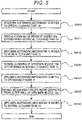
- the special operation in the present example is roughly divided into the special cleaning performed with a detergent, a normal cleaning performed thereafter, and drying performed thereafter.
- the specimen dispensing mechanism 13 moves from the normal cleaning tank 15 to the special cleaning tank 19 (step S200).
- the specimen dispensing nozzle 13a descends, and the specimen dispensing nozzle 13a is immersed in the detergent solution containing the detergent in the special cleaning tank 19.
- the syringe connected to the specimen dispensing nozzle 13a operates to aspirate the detergent solution to perform the special cleaning, and then the inner wall and the outer wall of the specimen dispensing nozzle 13a are cleaned (step S201).
- the specimen dispensing mechanism 13 causes the syringe to operate to discharge, from the specimen dispensing nozzle 13a, the detergent solution aspirated in the special cleaning tank 19 and the water from the tank (not shown), and then performs the internal cleaning on the specimen dispensing nozzle 13a (S203).
- the specimen dispensing mechanism 13 moves to the drying mechanism 17, and the specimen dispensing nozzle 13a descends (step S204).
- the drying mechanism 17 drops water droplets from the outer wall of the specimen dispensing nozzle 13a (step S205). Since the drying mechanism 17 blows the wind while the specimen dispensing nozzle 13a ascends, the water droplets can be evenly dropped in a height direction.
- the specimen dispensing mechanism 13 moves to the normal cleaning tank 15 (step S206).
- the two specimen dispensing mechanisms 13 and 14 are operated at the same time in order to increase a processing capacity.
- An actual operation pattern is a combination of the above-mentioned dispensing operation and special operation, and as illustrated in FIG. 6 , four operations are present.
- the two specimen dispensing mechanisms and 14 have the specimen aspiration position S1, the specimen discharge position C1, and the special cleaning tank 19 as common accessing locations, if the specimen dispensing mechanisms 13 and 14 are simply operated at the same time, the specimen dispensing mechanisms 13 and 14 may interfere with each other.
- FIGS. 7 to 9 a method for reducing a waiting time while preventing the mutual interference between the specimen dispensing mechanisms 13 and 14 will be described for each operation pattern.
- the dispensing operation of the specimen will be described, but the same dispensing operation may be performed for the reagent.
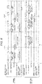
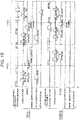
- Timing charts illustrated in FIGS. 7 to 9 illustrate time zones, in a convex shape, assigned to the operations of the specimen dispensing mechanisms 13 and 14, the normal cleaning in the normal cleaning tanks 15 and 16, the special cleaning in the special cleaning tank 19, and the drying performed by the drying mechanism when a series of the dispensing operations illustrated in FIG. 4 is one cycle.
- FIG. 7 is the timing chart illustrating the operations or the like of the specimen dispensing nozzles 13a and 14a when the special cleaning is not included in the test item set for the specimen as a required item.
- FIG. 7 corresponds to a pattern in which the specimen dispensing mechanisms 13 and 14 both perform the dispensing operation.
- the specimen dispensing mechanisms 13 and 14 both perform the dispensing operation illustrated in FIG. 4 , if the two specimen dispensing mechanisms 13 and 14 start the dispensing operation at the same time, the specimen dispensing mechanisms 13 and 14 may interfere with each other at the specimen aspiration position S1 and the specimen discharge position C1. Therefore, by shifting a start point (phase) of the dispensing operation of one specimen dispensing mechanism by half a cycle from the other specimen dispensing mechanism, the specimen dispensing mechanisms 13 and 14 can be prevented from interfering with each other. As a result, occurrence of the waiting time during the dispensing operation is prevented, and a speed-up of processing of the automatic analyzer can be achieved.
- the normal cleaning tanks dedicated to the specimen dispensing mechanisms 13 and 14 respectively are each provided at a position where only one of the plurality of specimen dispensing mechanisms 13 and 14 accesses, and when one specimen dispensing mechanism accesses the normal cleaning tank, the one specimen dispensing mechanism does not interfere with the other specimen dispensing mechanism.
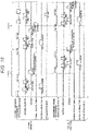
- FIG. 8 is the timing chart illustrating the operations or the like of the specimen dispensing mechanisms 13 and 14 when the test item set for the specimen includes one special cleaning as a required item.
- a pattern in which the specimen dispensing mechanism 13 performs the special operation and the specimen dispensing mechanism 14 performs the dispensing operation will be described as an example.
- a description is omitted.
- the one specimen dispensing mechanism when the one specimen dispensing mechanism accesses the special cleaning tank 19 during the special operation, and a trajectory where the other specimen dispensing mechanism reciprocates between the aspiration position S1 and the specimen discharge position C1 during the dispensing operation have an interference region. Therefore, as illustrated in FIG. 10 , when the specimen dispensing mechanism 13 accesses the special cleaning tank 19, if the specimen dispensing mechanism 14 tries to move to the specimen aspiration position S1, the specimen dispensing mechanisms 13 and 14 interfere with each other.
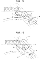
- FIG. 11 is a plan view illustrating a positional relationship of the specimen dispensing mechanisms 13 and 14 at a timing indicated by T1 in FIG. 8 .
- the controller 26 causes the specimen dispensing mechanism 13 during the special operation to access the position of the normal cleaning tank 15, so that the specimen dispensing mechanisms 13 and 14 can be prevented from interfering with each other.
- the specimen dispensing mechanism 13 must access the normal cleaning tank 15 during the special operation, and in the one cycle corresponding to one dispensing operation of the specimen dispensing mechanism 14, sufficient special cleaning cannot be performed, arid carryover of the previous specimen may occur. Therefore, in the present example, the special cleaning is divided into first special cleaning and subsequent second special cleaning, and the first special cleaning is carried out in a first cycle and the second special cleaning is carried out in a second cycle. Specifically, first, during the dispensing operation of the specimen dispensing mechanism 14 in the first cycle, the specimen dispensing mechanism 13 performs the first special cleaning, and the controller 26 causes the specimen dispensing mechanism 13 to access the retreat position when the specimen dispensing mechanism 14 moves in the interference region.
- the specimen dispensing mechanism 13 performs the second special cleaning, and the controller 26 causes the specimen dispensing mechanism 13 to access the retreat position when the specimen dispensing mechanism 14 moves in the interference region.
- the drying mechanism 17 is accessed to dry the specimen dispensing mechanism 13. Accordingly, with consideration of performing the drying after the special cleaning, in the present example, a time of the second special cleaning is shorter than that of the first special cleaning, and both the second special cleaning and the drying are performed in the second cycle. Specifically, during the dispensing operation of the specimen dispensing mechanism 14 in the second cycle, after the specimen dispensing mechanism 13 performs the second special cleaning, the specimen dispensing mechanism 13 accesses the retreat position when the specimen dispensing mechanism 14 moves in the interference region, and then the specimen dispensing mechanism 13 accesses the drying mechanism to be dried.
- the special cleaning is divided into two times, but if the specimen pump 24 is small and a pressure is small, the special cleaning may be divided into three or more times.
- the retreat position is not limited to the position of the normal cleaning tank 15, and the specimen dispensing mechanism 13 when the specimen dispensing mechanism 13 accesses the retreat position and the trajectory where the specimen dispensing mechanism 14 reciprocates between the specimen aspiration position S1 and the specimen discharge position C1 during the dispensing operation may not have the interference region.
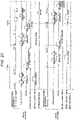
- FIG. 9 is the timing chart illustrating the operations or the like of the specimen dispensing mechanisms 13 and 14 when the test item set for the specimen includes special cleaning performed twice as required items.
- FIG. 9 corresponds to a pattern in which the specimen dispensing mechanisms 13 and 14 both perform the special operation.
- the special operation of each specimen dispensing mechanism has two cycles of the dispensing operation.
- the first special cleaning and the normal cleaning are performed in the first cycle, and the second special cleaning, the normal cleaning, and the drying are performed in the second cycle.
- FIG. 12 is a plan view illustrating a positional relationship of the specimen dispensing mechanisms 13 and 14 at a timing indicated by T2 in FIG. 9 .
- the controller 26 causes the specimen dispensing mechanism 14 to access the retreat position away from the special cleaning tank 19, specifically, the normal cleaning tank 16. By operating in this way, the specimen dispensing mechanisms 13 and 14 can be prevented from interfering with each other.
- the entire analyzer can be miniaturized and the manufacturing cost can be reduced. Even though the special cleaning tank is shared, the waiting time for avoiding the interference of the mechanisms can be prevented from being generated in each specimen dispensing mechanism, and a decrease in the processing capacity can be prevented. Therefore, the automatic analyzer that copes with micro-quantity of the specimen and high sensitivity of the analysis, may have a mechanism configuration with a high density, and has a high processing capacity can be achieved.
- FIG. 13 is a plan view illustrating a positional relationship of the specimen dispensing mechanisms 13 and 14 in the present example.
- the present example is an automatic analyzer in which a drying mechanism 57 shared by the specimen dispensing mechanisms 13 and 14 is disposed at a position where the specimen dispensing mechanisms 13 and 14 both access. Since the automatic analyzer of the present example requires not only one special cleaning tank but also one drying mechanism, the entire analyzer can be further miniaturized and the manufacturing cost can be further reduced.
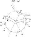
- FIG. 14 is a plan view illustrating a positional relationship of specimen dispensing mechanisms 27 and 28 in the present example.
- each sample dispensing mechanism is configured to linearly move between the specimen aspiration position S1 and the specimen discharge position C1
- each sample dispensing mechanism is configured to rotationally move between the specimen aspiration position S1 and the specimen discharge position C1.
- the specimen dispensing mechanisms 27 and 28 of the present example each include a mechanism that can coaxially rotate and move up and down, and can access the specimen discharge position C1 and the specimen aspiration position S1 provided in common for the two specimen dispensing mechanisms.
- a dedicated normal cleaning tank 34 and a dedicated drying mechanism 58 are disposed at a position where only the specimen dispensing mechanism 27 accesses
- a dedicated normal cleaning tank 35 and a dedicated drying mechanism 59 are disposed at a position where only the specimen dispensing mechanism 28 accesses.
- An automatic analyzer includes a special cleaning tank 19 that is commonly accessed by the specimen dispensing mechanisms 27 and 28, and the special cleaning tank 19 is on a circle trajectory TR1 same as that where the specimen discharge position C1, the specimen aspiration position S1, the normal cleaning tanks 34 and 35, and the drying mechanisms 58 and 59 are located.
- the position of the special cleaning tank 19 of the present example is between the normal cleaning tank 34 and the normal cleaning tank 35, and is on the trajectory TR1 on a specimen aspiration position S1 side.
- the special cleaning tank 19 is disposed at a position such that movement distances of the specimen dispensing mechanisms 27 and 28 are not significantly biased. This is because if the movement distance of the one specimen dispensing mechanism becomes long, movement to the special cleaning tank 19 may not be within a desired time, and a wasteful cycle may be required as a whole. Therefore, in the present example, the special cleaning tank 19 is located on the trajectory TR1 (an arc illustrated by a solid line in FIG. 14 ), the trajectory TR1 connecting a point symmetry position (P) of the specimen discharge position C1 with respect to a rotation center of the specimen dispensing mechanisms 27 and 28 and the specimen aspiration position S1 and being a relatively shorter trajectory.
- the trajectory TR1 an arc illustrated by a solid line in FIG. 14
- the movement distances of the specimen dispensing mechanisms 27 and 28 between the specimen discharge position C1 and the special cleaning tank 19 become almost equal, and an advantage that operations of the specimen dispensing mechanisms 27 and 28 can be easily unified presents. Since a distance between the specimen aspiration position S1 and the special cleaning tank 19 is relatively short, even though the one specimen dispensing mechanism passes through the specimen aspiration position S1 and accesses the special cleaning tank 19, the one specimen dispensing mechanism can be quickly retreated to the dedicated normal cleaning tank and can be prevented from interfering with the other specimen dispensing mechanism.
- a distance between the normal cleaning tank 34 and the special cleaning tank 19 is equal to a distance between the normal cleaning tank 35 and the special cleaning tank 19, and a waiting time for avoiding the interference of the specimen dispensing mechanism is prevented, so that a cleaning process can be performed efficiently.
- FIG. 15 is a timing chart illustrating operations or the like of the specimen dispensing mechanisms 27 and 28 of the present example when the test item set for the specimen includes the special cleaning performed once as a required item.
- a pattern in which the specimen dispensing mechanism 27 performs the special operation and the specimen dispensing mechanism 28 performs the dispensing operation will be described as an example. Similar to Example 1, two cycles are used for the special operation, whereas dispensing is performed once per cycle for the dispensing operation. For example, as illustrated in FIG.
- FIG. 16 is the timing chart illustrating operations or the like of the specimen dispensing mechanisms 27 and 28 of the present example when the test item set for the specimen includes two items requiring the special cleaning.
- the specimen dispensing mechanism 27 is located at a retreat position of the dedicated normal cleaning tank 34 or the like, and when the specimen dispensing mechanism 28 moves to a retreat position of the dedicated normal cleaning tank 35 or the like, the specimen dispensing mechanism 27 moves to the normal cleaning tank 19. Therefore, the specimen dispensing mechanisms can prevent physical interference with each other while preventing an unnecessary waiting time.
- FIG. 17 is a plan view illustrating a positional relationship of specimen dispensing mechanisms 27 and 28 according to a modification of Example 3.
- the modification has the same position such as the special cleaning tank 19 as in Example 3, but differs in that the modification has a plurality of specimen discharge positions C1a and C1b.
- a position of a point symmetry P described above varies depending on which of the specimen discharge positions C1a and C1b is used as a reference, and thus a point on the trajectory TR1 located between a point symmetry with respect to the specimen discharge position C1a and a point symmetry with respect to the specimen discharge position C1b is adopted as the convenient point symmetry P in this case.
- the specimen discharge positions are usually close to each other, the same effect can be exerted regardless of which position is used as a reference.
- FIG. 18 is a plan view illustrating a positional relationship of specimen dispensing mechanisms 45 and 46 in the present example.
- the specimen dispensing mechanisms 45 and 46 of the present example respectively include mechanisms rotationally moving around different axes, and pass through different trajectories TR2 and TR3.
- the common special cleaning tank 19 and the common specimen aspiration position S1 are located at intersections of the trajectories
- the dedicated normal cleaning tank 34 and the dedicated drying mechanism 58 are located on the trajectory TR2 in addition to a specimen discharge position C1c
- the dedicated normal cleaning tank 35 and the dedicated drying mechanism 59 are located on the trajectory TR3 in addition to a specimen discharge position C1d.
- FIG. 19 is the timing chart illustrating operations or the like of the specimen dispensing mechanisms 45 and 46 of the present example when the test item set for the specimen includes special cleaning performed once as a required item.
- a pattern in which the specimen dispensing mechanism 45 performs the dispensing operation and the specimen dispensing mechanism 46 performs the special operation will be described as an example.
- the specimen dispensing mechanism 45 when the specimen dispensing mechanism 46 is in the special cleaning tank 19, the specimen dispensing mechanism 45 is located at the specimen discharge position C1c, and when the specimen dispensing mechanism 46 ends the special cleaning and starts to move to the dedicated normal cleaning tank 35, the specimen dispensing mechanism 45 passes through the special cleaning tank 19 and moves to the dedicated normal cleaning tank 34. Therefore, the specimen dispensing mechanisms can prevent the physical interference with each other while preventing the unnecessary waiting time.
- FIG. 20 is the timing chart illustrating operations or the like of the specimen dispensing mechanisms 45 and 46 of the present example when the test item set for the specimen includes the special cleaning performed twice as required items.
- the specimen dispensing mechanism 45 located at a retreat position of the dedicated normal cleaning tank 34 or the like when the specimen dispensing mechanism 46 is in the special cleaning tank 19, and when the specimen dispensing mechanism 46 moves to a retreat position of the dedicated normal cleaning tank 35 or the like, the specimen dispensing mechanism 45 moves to the special cleaning tank 19. Therefore, the specimen dispensing mechanisms can prevent physical interference with each other while preventing an unnecessary waiting time.
- Examples 1 to 4 described above are described in detail for easy understanding of the invention, and are not necessarily limited to those including all the configurations described above.
- a part of a configuration of an example may be replaced with a configuration of another example, and the configuration of the example may also be added with the configuration of another example.
- a part of configurations of examples may be added to, deleted from, or replaced with another configuration.
Landscapes
- Analytical Chemistry (AREA)
- Physics & Mathematics (AREA)
- Health & Medical Sciences (AREA)
- Life Sciences & Earth Sciences (AREA)
- Chemical & Material Sciences (AREA)
- Biochemistry (AREA)
- General Health & Medical Sciences (AREA)
- General Physics & Mathematics (AREA)
- Immunology (AREA)
- Pathology (AREA)
- Mechanical Engineering (AREA)
- Engineering & Computer Science (AREA)
- Automatic Analysis And Handling Materials Therefor (AREA)
Abstract
Description
- The present invention relates to an automatic analyzer.
- In an automatic analyzer, in order to prevent an aspiration or discharge amount from fluctuating and contamination from occurring, a dispensing nozzle that dispenses a specimen or a reagent is generally cleaned by a cleaning mechanism to be repeatedly used. However, micro-quantity of the specimen or the like and high sensitivity of analysis have advanced year by year, and thus if the dispensing nozzle is insufficiently cleaned, an influence on an analysis accuracy increases, and it is required more than ever to improve a cleaning performance of the dispensing nozzle.
- Therefore, as a technique for improving the cleaning performance of the dispensing nozzle, it is known that a cleaning solution containing a detergent is used to perform special cleaning stronger than special cleaning performed by cleaning water. For example,
JP-A-2017-110913 - However, the automatic analyzer in the related art disclosed in
JP-A-2017-110913 - An object of the invention is to provide an automatic analyzer capable of performing special cleaning while preventing an increase in a size of the entire analyzer and suppressing a manufacturing cost.
- In order to solve the above problems, the invention provides an automatic analyzer that dispenses a specimen and a reagent individually into a reaction vessel to make the specimen and the reagent react with each other and measures a liquid obtained by the reaction. The automatic analyzer includes: a plurality of dispensing mechanisms; a controller which controls the plurality of dispensing mechanisms; a normal cleaning tank dedicated to each of the dispensing mechanisms, which is provided at a position where only one of the plurality of dispensing mechanisms accesses, and performs normal cleaning with respect to the dispensing mechanism that has accessed; and a special cleaning tank shared by each of the dispensing mechanisms, which is provided at a position where all of the plurality of dispensing mechanisms access, and performs cleaning different from the normal cleaning with respect to the dispensing mechanism that has accessed.
- The invention can provide the automatic analyzer capable of performing the special cleaning while preventing the increase in the size of the entire analyzer and suppressing the manufacturing cost.
-
-
FIG. 1 is a configuration diagram schematically illustrating an analysis unit in an automatic analyzer according to Example 1. -
FIG. 2 is a side view of a specimen dispensing mechanism in Example 1. -
FIG. 3 is a plan view illustrating a positional relationship of specimen dispensing mechanisms in Example 1. -
FIG. 4 is a flowchart of a dispensing operation. -
FIG. 5 is a flowchart of a special operation. -
FIG. 6 is a diagram illustrating a combination of operation patterns in each specimen dispensing mechanism. -
FIG. 7 is a timing chart in a case where both specimen dispensing mechanisms perform a dispensing operation. -
FIG. 8 is a timing chart in a case where one specimen dispensing mechanism performs a special operation and the other specimen dispensing mechanism performs a dispensing operation. -
FIG. 9 is a timing chart in a case where both specimen dispensing mechanisms perform a special operation. -
FIG. 10 is a side view illustrating a state where the specimen dispensing mechanisms interfere with each other. -
FIG. 11 is a plan view illustrating a positional relationship of the specimen dispensing mechanisms at a timing indicated by T1 inFIG. 8 . -
FIG. 12 is a plan view illustrating a positional relationship of the specimen dispensing mechanisms at a timing indicated by T2 inFIG. 9 . -
FIG. 13 is a plan view illustrating a positional relationship of specimen dispensing mechanisms according to Example 2. -
FIG. 14 is a plan view illustrating a positional relationship of specimen dispensing mechanisms according to Example 3. -
FIG. 15 is a timing chart in a case where one specimen dispensing mechanism performs a special operation and the other specimen dispensing mechanism performs a dispensing operation in Example 3. -
FIG. 16 is a timing chart in a case where both specimen dispensing mechanisms perform a special operation in Example 3. -
FIG. 17 is a plan view illustrating a positional relationship of specimen dispensing mechanisms according to a modification of Example 3. -
FIG. 18 is a plan view illustrating a positional relationship of specimen dispensing mechanisms according to Example 4. -
FIG. 19 is a timing chart in a case where one specimen dispensing mechanism performs a dispensing operation and the other specimen dispensing mechanism performs a special operation in Example 4. -
FIG. 20 is a timing chart in a case where both specimen dispensing mechanisms perform a special- operation in Example 4. - Hereinafter, embodiments of an automatic analyzer of the invention will be described with reference to the drawings.
-
FIG. 1 is a configuration diagram schematically illustrating an analysis unit in an automatic analyzer according to the present example. As illustrated inFIG. 1 ,reaction vessels 2 are disposed in a circumferential shape on areaction disk 1, and a plurality ofreagent bottles 12 are arranged in the circumferential shape in areagent disk 11.Reagent dispensing mechanisms 7 to 10 are connected to areagent pump 23 via a syringe.Specimen containers 20 containing a test specimen such as blood or urine can be moved between thereaction disk 1 and thereagent disk 11 by aspecimen transport mechanism 22 while thespecimen containers 20 are placed on arack 21. - A
cleaning mechanism 3, aspectrophotometer 4,stirring mechanisms reagent disk 11, and aspecimen pump 24 are disposed around thereaction disk 1, and acleaning pump 25 is connected to thecleaning mechanism 3 for cleaning the usedreaction vessel 2.Specimen dispensing mechanisms reaction disk 1 and thespecimen transport mechanism 22, and are connected to thespecimen pump 24 via the syringe. - The automatic analyzer according to the present example includes
cleaning tanks 30 to 33 disposed in operation trajectories of thereagent dispensing mechanisms 7 to 10, anormal cleaning tank 15 and adrying mechanism 17 disposed in an operation trajectory of thespecimen dispensing mechanism 13, anormal cleaning tank 16 and adrying mechanism 18 disposed in an operation trajectory of thespecimen dispensing mechanism 14, and aspecial cleaning tank 19 disposed in the operation trajectories of thespecimen dispensing mechanism reagent dispensing mechanisms 7 to 10. - Here, the
specimen dispensing mechanisms nozzles nozzles specimen container 20 into thereaction vessel 2. - The dispensing
nozzles normal cleaning tanks specimen dispensing nozzles specimen dispensing nozzles special cleaning tank 19 shared by thespecimen dispensing nozzles normal cleaning tanks nozzles drying mechanisms specimen dispensing nozzles - The automatic analyzer according to the present example includes a
controller 26 having a function as an analysis unit configured to analyze the test specimen in thereaction vessel 2, and an operation of each mechanism connected to thecontroller 26 is controlled. - Next, a schematic configuration of the
specimen dispensing mechanism FIG. 2. FIG. 2 is a side view of thespecimen dispensing mechanism FIG. 2 , thespecimen dispensing mechanisms specimen dispensing nozzles arm 44 for holding thesample dispensing nozzle vertical mechanism 41 that moves thearm 44 vertically, arotating mechanism 42 that rotates thearm 44, and ahorizontal mechanism 43 that moves thearm 44 horizontally. Therotating mechanism 42 may be a horizontal mechanism that moves in a direction orthogonal to thehorizontal mechanism 43. -
FIG. 3 is a plan view illustrating a positional relationship of thespecimen dispensing mechanisms FIG. 3 , the present example is an automatic analyzer in which thedrying mechanisms specimen dispensing mechanisms specimen dispensing mechanisms - A specimen aspiration position S1 and a specimen discharge position C1 are respectively disposed at ends of the operation trajectories of the
specimen dispensing mechanisms normal cleaning tanks drying mechanisms specimen dispensing mechanisms special cleaning tank 19 shared by thespecimen dispensing mechanisms - Here, the special cleaning performed in the
special cleaning tank 19 uses a detergent solution containing a detergent to perform a stronger cleaning than the normal cleaning, and is carried out when the special cleaning is set as a required item in the test item set for the specimen. A method using a detergent will be described as a specific cleaning method for the special cleaning, but the method is not limited thereto, and a method using ultrasonic waves may be used. - The
drying mechanisms normal cleaning tanks normal cleaning tanks drying mechanisms specimen dispensing nozzle 13a and blows off a cleaning solution with wind. Thedrying mechanism 17 may be a dry port using vacuum aspiration or a wiper for wiping off the cleaning solution. By providing the dryingmechanisms specimen dispensing nozzle 13a after the special cleaning can be prevented from being carried into the specimen, and high analysis accuracy can be maintained. - Next, a flow of a specimen dispensing operation will be described with reference to
FIG. 4 . Here, a dispensing operation of thespecimen dispensing mechanism 13 of the twospecimen dispensing mechanisms - First, the
specimen dispensing mechanism 13 moves from thenormal cleaning tank 15 to the specimen aspiration position S1 on the specimen container 20 (step S100). - At this specimen aspiration position S1, the
specimen dispensing nozzle 13a descends, and thespecimen dispensing nozzle 13a is immersed in the specimen contained in thespecimen container 20. In this state, the syringe operates to aspirate the specimen, and then thespecimen dispensing nozzle 13a ascends (step S101). - Then, the
specimen dispensing mechanism 13 moves from the specimen aspiration position S1 to the normal cleaning tank 15 (step S102). At a position of thenormal cleaning tank 15, an outer wall of thespecimen dispensing nozzle 13a is cleaned by water (step S103). - Then, the
specimen dispensing mechanism 13 moves to the specimen discharge position C1 on apredetermined reaction vessel 2 on the reaction disk 1 (step S104). - The
specimen dispensing nozzle 13a descends, the syringe operates to discharge the specimen, and when the discharge of the specimen is ended, thespecimen dispensing nozzle 13a ascends (step S105). - Then, the
specimen dispensing mechanism 13 moves to the normal cleaning tank 15 (step S106). - Here, when the same specimen is continuously dispensed, one cycle ends according to the flow. However, when a last dispensing of the same specimen is performed, the normal cleaning is further performed by the operation of the syringe. Specifically, by discharging the water in a tank (not shown) from the
specimen dispensing nozzle 13a, not only the outer wall but also an inner wall of thespecimen dispensing nozzle 13a is cleaned (internal cleaning). - Next, a flow of a special operation performing a special cleaning will be described with reference to
FIG. 5 . Here, a dispensing operation of thespecimen dispensing mechanism 13 of the twospecimen dispensing mechanisms - The special operation in the present example is roughly divided into the special cleaning performed with a detergent, a normal cleaning performed thereafter, and drying performed thereafter.
- Specifically, first, the
specimen dispensing mechanism 13 moves from thenormal cleaning tank 15 to the special cleaning tank 19 (step S200). - Next, the
specimen dispensing nozzle 13a descends, and thespecimen dispensing nozzle 13a is immersed in the detergent solution containing the detergent in thespecial cleaning tank 19. - In this state, the syringe connected to the
specimen dispensing nozzle 13a operates to aspirate the detergent solution to perform the special cleaning, and then the inner wall and the outer wall of thespecimen dispensing nozzle 13a are cleaned (step S201). - Then, the
specimen dispensing nozzle 13a ascends, and thespecimen dispensing mechanism 13 moves to the normal cleaning tank 15 (step S202). - Here, the
specimen dispensing mechanism 13 causes the syringe to operate to discharge, from thespecimen dispensing nozzle 13a, the detergent solution aspirated in thespecial cleaning tank 19 and the water from the tank (not shown), and then performs the internal cleaning on thespecimen dispensing nozzle 13a (S203). - Then, the
specimen dispensing mechanism 13 moves to thedrying mechanism 17, and thespecimen dispensing nozzle 13a descends (step S204). - Here, the
drying mechanism 17 drops water droplets from the outer wall of thespecimen dispensing nozzle 13a (step S205). Since thedrying mechanism 17 blows the wind while thespecimen dispensing nozzle 13a ascends, the water droplets can be evenly dropped in a height direction. - Then, the
specimen dispensing mechanism 13 moves to the normal cleaning tank 15 (step S206). - Next, an actual operation method of the two
specimen dispensing mechanisms specimen dispensing mechanisms FIG. 6 , four operations are present. However, since the two specimen dispensing mechanisms and 14 have the specimen aspiration position S1, the specimen discharge position C1, and thespecial cleaning tank 19 as common accessing locations, if thespecimen dispensing mechanisms specimen dispensing mechanisms - Therefore, with reference to
FIGS. 7 to 9 , a method for reducing a waiting time while preventing the mutual interference between thespecimen dispensing mechanisms FIGS. 7 to 9 illustrate time zones, in a convex shape, assigned to the operations of thespecimen dispensing mechanisms normal cleaning tanks special cleaning tank 19, and the drying performed by the drying mechanism when a series of the dispensing operations illustrated inFIG. 4 is one cycle. -
FIG. 7 is the timing chart illustrating the operations or the like of thespecimen dispensing nozzles FIG. 7 corresponds to a pattern in which thespecimen dispensing mechanisms - Since the
specimen dispensing mechanisms FIG. 4 , if the twospecimen dispensing mechanisms specimen dispensing mechanisms specimen dispensing mechanisms specimen dispensing mechanisms specimen dispensing mechanisms FIG. 8 is the timing chart illustrating the operations or the like of thespecimen dispensing mechanisms specimen dispensing mechanism 13 performs the special operation and thespecimen dispensing mechanism 14 performs the dispensing operation will be described as an example. Here, since the same operation is performed in a pattern in which thespecimen dispensing mechanism 13 performs the dispensing operation and thespecimen dispensing mechanism 14 performs the special operation, a description is omitted. - First, as a premise of the present example, the one specimen dispensing mechanism when the one specimen dispensing mechanism accesses the
special cleaning tank 19 during the special operation, and a trajectory where the other specimen dispensing mechanism reciprocates between the aspiration position S1 and the specimen discharge position C1 during the dispensing operation have an interference region. Therefore, as illustrated inFIG. 10 , when thespecimen dispensing mechanism 13 accesses thespecial cleaning tank 19, if thespecimen dispensing mechanism 14 tries to move to the specimen aspiration position S1, thespecimen dispensing mechanisms - Therefore, in the present example, in a case where the
specimen dispensing mechanism 13 performs the special operation and the otherspecimen dispensing mechanism 14 performs the dispensing operation, thespecimen dispensing mechanism 13 accesses a retreat position away from thespecial cleaning tank 19 when the otherspecimen dispensing mechanism 14 moves in the interference region.FIG. 11 is a plan view illustrating a positional relationship of thespecimen dispensing mechanisms FIG. 8 . As illustrated inFIG. 8 , when thespecimen dispensing mechanism 14 during the dispensing operation moves in the interference region, thecontroller 26 causes thespecimen dispensing mechanism 13 during the special operation to access the position of thenormal cleaning tank 15, so that thespecimen dispensing mechanisms - Accordingly, the
specimen dispensing mechanism 13 must access thenormal cleaning tank 15 during the special operation, and in the one cycle corresponding to one dispensing operation of thespecimen dispensing mechanism 14, sufficient special cleaning cannot be performed, arid carryover of the previous specimen may occur. Therefore, in the present example, the special cleaning is divided into first special cleaning and subsequent second special cleaning, and the first special cleaning is carried out in a first cycle and the second special cleaning is carried out in a second cycle. Specifically, first, during the dispensing operation of thespecimen dispensing mechanism 14 in the first cycle, thespecimen dispensing mechanism 13 performs the first special cleaning, and thecontroller 26 causes thespecimen dispensing mechanism 13 to access the retreat position when thespecimen dispensing mechanism 14 moves in the interference region. During the dispensing operation of thespecimen dispensing mechanism 14 in the second cycle, thespecimen dispensing mechanism 13 performs the second special cleaning, and thecontroller 26 causes thespecimen dispensing mechanism 13 to access the retreat position when thespecimen dispensing mechanism 14 moves in the interference region. - In the special operation of the present example, after the special cleaning is performed, the
drying mechanism 17 is accessed to dry thespecimen dispensing mechanism 13. Accordingly, with consideration of performing the drying after the special cleaning, in the present example, a time of the second special cleaning is shorter than that of the first special cleaning, and both the second special cleaning and the drying are performed in the second cycle. Specifically, during the dispensing operation of thespecimen dispensing mechanism 14 in the second cycle, after thespecimen dispensing mechanism 13 performs the second special cleaning, thespecimen dispensing mechanism 13 accesses the retreat position when thespecimen dispensing mechanism 14 moves in the interference region, and then thespecimen dispensing mechanism 13 accesses the drying mechanism to be dried. - In the present example, the special cleaning is divided into two times, but if the
specimen pump 24 is small and a pressure is small, the special cleaning may be divided into three or more times. The retreat position is not limited to the position of thenormal cleaning tank 15, and thespecimen dispensing mechanism 13 when thespecimen dispensing mechanism 13 accesses the retreat position and the trajectory where thespecimen dispensing mechanism 14 reciprocates between the specimen aspiration position S1 and the specimen discharge position C1 during the dispensing operation may not have the interference region. -
FIG. 9 is the timing chart illustrating the operations or the like of thespecimen dispensing mechanisms FIG. 9 corresponds to a pattern in which thespecimen dispensing mechanisms - As illustrated in
FIG. 9 , the special operation of each specimen dispensing mechanism has two cycles of the dispensing operation. The first special cleaning and the normal cleaning are performed in the first cycle, and the second special cleaning, the normal cleaning, and the drying are performed in the second cycle. -
FIG. 12 is a plan view illustrating a positional relationship of thespecimen dispensing mechanisms FIG. 9 . As illustrated inFIG. 12 , when the special cleaning of thespecimen dispensing mechanism 13 is performed in thespecial cleaning tank 19, thecontroller 26 causes thespecimen dispensing mechanism 14 to access the retreat position away from thespecial cleaning tank 19, specifically, thenormal cleaning tank 16. By operating in this way, thespecimen dispensing mechanisms - According to the present example described above, since only one special cleaning tank larger than the normal cleaning tank or the drying mechanism is required, the entire analyzer can be miniaturized and the manufacturing cost can be reduced. Even though the special cleaning tank is shared, the waiting time for avoiding the interference of the mechanisms can be prevented from being generated in each specimen dispensing mechanism, and a decrease in the processing capacity can be prevented. Therefore, the automatic analyzer that copes with micro-quantity of the specimen and high sensitivity of the analysis, may have a mechanism configuration with a high density, and has a high processing capacity can be achieved.
- In the present example, since the drying mechanisms dedicated for the specimen dispensing mechanisms respectively are provided, an operation for avoiding the interference during the drying becomes unnecessary, and an increase in the waiting time can be prevented.
-
FIG. 13 is a plan view illustrating a positional relationship of thespecimen dispensing mechanisms FIG. 13 , the present example is an automatic analyzer in which adrying mechanism 57 shared by thespecimen dispensing mechanisms specimen dispensing mechanisms -
FIG. 14 is a plan view illustrating a positional relationship ofspecimen dispensing mechanisms - As illustrated in
FIG. 14 , thespecimen dispensing mechanisms normal cleaning tank 34 and adedicated drying mechanism 58 are disposed at a position where only thespecimen dispensing mechanism 27 accesses, and a dedicatednormal cleaning tank 35 and adedicated drying mechanism 59 are disposed at a position where only thespecimen dispensing mechanism 28 accesses. - An automatic analyzer according to the present example includes a
special cleaning tank 19 that is commonly accessed by thespecimen dispensing mechanisms special cleaning tank 19 is on a circle trajectory TR1 same as that where the specimen discharge position C1, the specimen aspiration position S1, thenormal cleaning tanks mechanisms special cleaning tank 19 of the present example is between thenormal cleaning tank 34 and thenormal cleaning tank 35, and is on the trajectory TR1 on a specimen aspiration position S1 side. - It is desirable that the
special cleaning tank 19 is disposed at a position such that movement distances of thespecimen dispensing mechanisms special cleaning tank 19 may not be within a desired time, and a wasteful cycle may be required as a whole. Therefore, in the present example, thespecial cleaning tank 19 is located on the trajectory TR1 (an arc illustrated by a solid line inFIG. 14 ), the trajectory TR1 connecting a point symmetry position (P) of the specimen discharge position C1 with respect to a rotation center of thespecimen dispensing mechanisms specimen dispensing mechanisms special cleaning tank 19 become almost equal, and an advantage that operations of thespecimen dispensing mechanisms special cleaning tank 19 is relatively short, even though the one specimen dispensing mechanism passes through the specimen aspiration position S1 and accesses thespecial cleaning tank 19, the one specimen dispensing mechanism can be quickly retreated to the dedicated normal cleaning tank and can be prevented from interfering with the other specimen dispensing mechanism. That is, according to the present example, a distance between thenormal cleaning tank 34 and thespecial cleaning tank 19 is equal to a distance between thenormal cleaning tank 35 and thespecial cleaning tank 19, and a waiting time for avoiding the interference of the specimen dispensing mechanism is prevented, so that a cleaning process can be performed efficiently. - Here, a case where the
specimen dispensing mechanisms special cleaning tank 19 can be used. Therefore, a form in which rotation center axes of thespecimen dispensing mechanisms -
FIG. 15 is a timing chart illustrating operations or the like of thespecimen dispensing mechanisms specimen dispensing mechanism 27 performs the special operation and thespecimen dispensing mechanism 28 performs the dispensing operation will be described as an example. Similar to Example 1, two cycles are used for the special operation, whereas dispensing is performed once per cycle for the dispensing operation. For example, as illustrated inFIG. 15 , after thespecimen dispensing mechanism 27 performing the special operation moves from thenormal cleaning tank 34 to thespecial cleaning mechanism 19 to be performed with the special cleaning, if thespecimen dispensing mechanism 27 moves thenormal cleaning tank 34 to thespecial cleaning mechanism 19 to be performed with the normal cleaning and moves from thenormal cleaning tank 34 to thespecial cleaning mechanism 19 to be performed with the special cleaning again, thespecimen dispensing mechanism 27 moves from thespecial cleaning mechanism 19 to thenormal cleaning tank 34 to be performed with the normal cleaning, and moves from thenormal cleaning tank 34 to thedrying mechanism 58 to be dried, and then moves from thedrying mechanism 58 to thenormal cleaning tank 34. -
FIG. 16 is the timing chart illustrating operations or the like of thespecimen dispensing mechanisms specimen dispensing mechanism 28 is in thespecial cleaning tank 19, thespecimen dispensing mechanism 27 is located at a retreat position of the dedicatednormal cleaning tank 34 or the like, and when thespecimen dispensing mechanism 28 moves to a retreat position of the dedicatednormal cleaning tank 35 or the like, thespecimen dispensing mechanism 27 moves to thenormal cleaning tank 19. Therefore, the specimen dispensing mechanisms can prevent physical interference with each other while preventing an unnecessary waiting time. -
FIG. 17 is a plan view illustrating a positional relationship ofspecimen dispensing mechanisms FIG. 17 , the modification has the same position such as thespecial cleaning tank 19 as in Example 3, but differs in that the modification has a plurality of specimen discharge positions C1a and C1b. A position of a point symmetry P described above varies depending on which of the specimen discharge positions C1a and C1b is used as a reference, and thus a point on the trajectory TR1 located between a point symmetry with respect to the specimen discharge position C1a and a point symmetry with respect to the specimen discharge position C1b is adopted as the convenient point symmetry P in this case. However, since the specimen discharge positions are usually close to each other, the same effect can be exerted regardless of which position is used as a reference. -
FIG. 18 is a plan view illustrating a positional relationship ofspecimen dispensing mechanisms FIG. 18 , thespecimen dispensing mechanisms special cleaning tank 19 and the common specimen aspiration position S1 are located at intersections of the trajectories, the dedicatednormal cleaning tank 34 and thededicated drying mechanism 58 are located on the trajectory TR2 in addition to a specimen discharge position C1c, and the dedicatednormal cleaning tank 35 and thededicated drying mechanism 59 are located on the trajectory TR3 in addition to a specimen discharge position C1d. -
FIG. 19 is the timing chart illustrating operations or the like of thespecimen dispensing mechanisms specimen dispensing mechanism 45 performs the dispensing operation and thespecimen dispensing mechanism 46 performs the special operation will be described as an example. - For example, when the
specimen dispensing mechanism 46 is in thespecial cleaning tank 19, thespecimen dispensing mechanism 45 is located at the specimen discharge position C1c, and when thespecimen dispensing mechanism 46 ends the special cleaning and starts to move to the dedicatednormal cleaning tank 35, thespecimen dispensing mechanism 45 passes through thespecial cleaning tank 19 and moves to the dedicatednormal cleaning tank 34. Therefore, the specimen dispensing mechanisms can prevent the physical interference with each other while preventing the unnecessary waiting time. -
FIG. 20 is the timing chart illustrating operations or the like of thespecimen dispensing mechanisms specimen dispensing mechanism 45 located at a retreat position of the dedicatednormal cleaning tank 34 or the like when thespecimen dispensing mechanism 46 is in thespecial cleaning tank 19, and when thespecimen dispensing mechanism 46 moves to a retreat position of the dedicatednormal cleaning tank 35 or the like, thespecimen dispensing mechanism 45 moves to thespecial cleaning tank 19. Therefore, the specimen dispensing mechanisms can prevent physical interference with each other while preventing an unnecessary waiting time. - The invention is not limited to Examples 1 to 4 described above, and includes various modifications. For example, Examples 1 to 4 described above are described in detail for easy understanding of the invention, and are not necessarily limited to those including all the configurations described above. A part of a configuration of an example may be replaced with a configuration of another example, and the configuration of the example may also be added with the configuration of another example. A part of configurations of examples may be added to, deleted from, or replaced with another configuration.
- 1
- reaction disk
- 2
- reaction vessels
- 3
- cleaning mechanism
- 4
- spectrophotometer
- 5, 6
- stirring mechanisms
- 7 to 10
- reagent dispensing mechanisms
- 11
- reagent disk12 reagent bottles
- 13, 14, 27, 28, 45, 46
- specimen dispensing mechanism
- 13a, 14a
- dispensing nozzles
- 15, 16, 34, 35
- normal cleaning tank
- 17, 18, 57, 58, 59
- drying mechanism
- 19
- special cleaning tank (special cleaning mechanism)
- 20
- specimen containers
- 21
- rack
- 22
- specimen transport mechanism
- 23
- reagent pump
- 24
- specimen pump
- 25
- cleaning pump
- 26
- controller
- 30 to 33
- cleaning tanks
- 41
- vertical mechanism
- 42
- rotating mechanism
- 43
- horizontal mechanism
- 44
- arm
- S1
- specimen aspiration position
- C1, C1a, C1b, C1c, C1d
- specimen discharge position
- TR1, TR2, TR3
- trajectory
Claims (10)
- An automatic analyzer that dispenses a specimen and a reagent individually into a reaction vessel so as to make the specimen and the reagent react with each other and measures a liquid obtained by the reaction, the automatic analyzer comprising:a plurality of dispensing mechanisms;a controller which controls the plurality of dispensing mechanisms;a normal cleaning tank dedicated to each of the dispensing mechanisms, which is provided at a position where only one of the plurality of dispensing mechanisms accesses, and performs normal cleaning with respect to the dispensing mechanism that has accessed; anda special cleaning tank shared by each of the dispensing mechanisms, which is provided at a position where all of the plurality of dispensing mechanisms access, and performs cleaning different from the normal cleaning with respect to the dispensing mechanism that has accessed.
- The automatic analyzer according to claim 1,wherein each of the dispensing mechanisms has a dispensing operation, in which each of the dispensing mechanisms reciprocates between an aspiration position of the specimen or the reagent and a discharge position of the specimen or the reagent and accesses the normal cleaning tank in the middle of reciprocating, and a special operation, in which special cleaning is performed with respect to the dispensing mechanism in the special cleaning tank,wherein one dispensing mechanism at a time when the one dispensing mechanism accesses the special cleaning tank during the special operation, and a trajectory where another dispensing mechanism reciprocates between the aspiration position and the discharge position during the dispensing operation have an interference region, andwherein in a case where the one dispensing mechanism performs the special operation and the other dispensing mechanism performs the dispensing operation, the controller causes the one dispensing mechanism to access a retreat position away from the special cleaning tank, when the other dispensing mechanism moves in the interference region.
- The automatic analyzer according to claim 2,wherein the special cleaning includes a first special cleaning and a subsequent second special cleaning,wherein the controller controls such that when the other dispensing mechanism performs the dispensing operation of a first cycle, the one dispensing mechanism performs the first special cleaning, and while the other dispensing mechanism moves in the interference region, the one dispensing mechanism accesses the retreat position, andwherein the controller controls such that when the other dispensing mechanism performs the dispensing operation of a second cycle, the one dispensing mechanism performs the second special cleaning, and while the other dispensing mechanism moves in the interference region, the one dispensing mechanism accesses the retreat position.
- The automatic analyzer according to claim 3,wherein in the special operation, after the special cleaning is performed, the dispensing mechanism accesses a drying mechanism and drying of the dispensing mechanism is performed, andwherein the controller controls such that when the other dispensing mechanism performs the dispensing operation of the second cycle, the one dispensing mechanism performs the second special cleaning shorter than the first special cleaning, and accesses the retreat position while the other dispensing mechanism moves in the interference region, and thereafter, the one dispensing mechanism accesses the drying mechanism and drying of the one dispensing mechanism is performed.
- The automatic analyzer according to any one of claims 2 to 4,wherein the one dispensing mechanism at a time when the one dispensing mechanism accesses the normal cleaning tank, and a trajectory where the other dispensing mechanism reciprocates between the aspiration position and the discharge position during the dispensing operation do not have an interference region, andwherein the retreat position is a position of the normal cleaning tank.
- The automatic analyzer according to claim 1,wherein each of the dispensing mechanisms has a dispensing operation, in which each of the dispensing mechanisms reciprocates between an aspiration position of the specimen or the reagent and a discharge position of the specimen or the reagent and accesses the normal cleaning tank in the middle of reciprocating, and a special operation, in which special cleaning is performed with respect to the dispensing mechanism in the special cleaning tank,wherein one dispensing mechanism at a time when the one dispensing mechanism accesses the special cleaning tank during the special operation, and a trajectory where another dispensing mechanism reciprocates between the aspiration position and the discharge position during the dispensing operation have an interference region, andwherein in a case where the one dispensing mechanism performs the special operation and the other dispensing mechanism also performs the special operation, the controller causes the other dispensing mechanism to access a retreat position away from the special cleaning tank, when the one dispensing mechanism performs the special cleaning.
- The automatic analyzer according to claim 6,
wherein the retreat position is a position of the normal cleaning tank. - An automatic analyzer according to claim 1,wherein the plurality of dispensing mechanisms rotate coaxially and reciprocate between an aspiration position of the specimen or the reagent and a discharge position of the specimen or the reagent, andwherein the special cleaning tank is located between the normal cleaning tanks and on the aspiration position side.
- An automatic analyzer according to claim 8,
wherein the special cleaning tank is located on a trajectory that connects a point symmetry position of the discharge position with respect to a rotation center and the aspiration position and is relatively shorter. - An automatic analyzer according to claim 1,wherein the plurality of dispensing mechanisms rotate around different axes and reciprocate between an aspiration position of the specimen or the reagent and a discharge position of the specimen or the reagent in different trajectories, andwherein the special cleaning tank is located at an intersection of the trajectories.
Applications Claiming Priority (2)
| Application Number | Priority Date | Filing Date | Title |
|---|---|---|---|
| JP2019171369 | 2019-09-20 | ||
| PCT/JP2020/035543 WO2021054456A1 (en) | 2019-09-20 | 2020-09-18 | Automatic analysis device |
Publications (3)
| Publication Number | Publication Date |
|---|---|
| EP4033253A1 true EP4033253A1 (en) | 2022-07-27 |
| EP4033253A4 EP4033253A4 (en) | 2023-09-13 |
| EP4033253B1 EP4033253B1 (en) | 2025-09-10 |
Family
ID=74884046
Family Applications (1)
| Application Number | Title | Priority Date | Filing Date |
|---|---|---|---|
| EP20864733.9A Active EP4033253B1 (en) | 2019-09-20 | 2020-09-18 | Automatic analysis device |
Country Status (5)
| Country | Link |
|---|---|
| US (1) | US12510552B2 (en) |
| EP (1) | EP4033253B1 (en) |
| JP (1) | JP7600127B2 (en) |
| CN (1) | CN114424068B (en) |
| WO (1) | WO2021054456A1 (en) |
Families Citing this family (1)
| Publication number | Priority date | Publication date | Assignee | Title |
|---|---|---|---|---|
| JP7592191B2 (en) * | 2021-11-05 | 2024-11-29 | 株式会社日立ハイテク | Pressure sensor and dispensing device |
Family Cites Families (26)
| Publication number | Priority date | Publication date | Assignee | Title |
|---|---|---|---|---|
| US4647432A (en) * | 1982-11-30 | 1987-03-03 | Japan Tectron Instruments Corporation Tokuyama Soda Kabushiki Kaisha | Automatic analysis apparatus |
| JP2796352B2 (en) * | 1989-05-10 | 1998-09-10 | 株式会社日立製作所 | Particle counting device |
| JP3972012B2 (en) * | 2003-03-19 | 2007-09-05 | 株式会社日立ハイテクノロジーズ | Sample dispensing mechanism and automatic analyzer equipped with the same |
| US7186378B2 (en) * | 2003-07-18 | 2007-03-06 | Dade Behring Inc. | Liquid sampling probe and cleaning fluidics system |
| JP4408404B2 (en) * | 2004-09-17 | 2010-02-03 | 株式会社日立ハイテクノロジーズ | Automatic analyzer |
| JP2009042067A (en) * | 2007-08-09 | 2009-02-26 | Hitachi High-Technologies Corp | Automatic analyzer |
| JP5107146B2 (en) * | 2008-06-11 | 2012-12-26 | 株式会社日立ハイテクノロジーズ | Automatic analyzer |
| JP5300447B2 (en) * | 2008-12-04 | 2013-09-25 | ベックマン コールター, インコーポレイテッド | Automatic analyzer and sample dispensing method in automatic analyzer |
| JP2010286420A (en) * | 2009-06-15 | 2010-12-24 | Hitachi High-Technologies Corp | Dispensing nozzle cleaning method, automatic analyzer, and container |
| JP2011106828A (en) * | 2009-11-12 | 2011-06-02 | Hitachi High-Technologies Corp | Dispensing device, automated analysis apparatus, and dispensing method |
| US9442128B2 (en) * | 2011-10-18 | 2016-09-13 | Hitachi High-Technologies Corporation | Automated analyzer |
| WO2013099660A1 (en) * | 2011-12-26 | 2013-07-04 | 株式会社日立ハイテクノロジーズ | Automatic analyzer and method for washing sample-pipetting probe |
| JP5898972B2 (en) * | 2012-01-23 | 2016-04-06 | 株式会社日立ハイテクノロジーズ | Automatic analyzer |
| JP6058277B2 (en) * | 2012-04-23 | 2017-01-11 | 東芝メディカルシステムズ株式会社 | Automatic analyzer |
| WO2014175018A1 (en) * | 2013-04-22 | 2014-10-30 | 株式会社日立ハイテクノロジーズ | Automatic analysis device |
| CN110031641A (en) * | 2013-09-12 | 2019-07-19 | 株式会社日立高新技术 | Nozzle cleaning method and automatic analysing apparatus |
| JP6521567B2 (en) * | 2014-02-27 | 2019-05-29 | キヤノンメディカルシステムズ株式会社 | Clinical examination equipment |
| JP6310767B2 (en) * | 2014-05-13 | 2018-04-11 | 日本電子株式会社 | Automatic analyzer and nozzle cleaning method |
| EP4425145A3 (en) * | 2015-03-20 | 2025-01-08 | Hitachi High-Tech Corporation | Automatic analysis device and automatic analysis method |
| JP6506591B2 (en) * | 2015-03-31 | 2019-04-24 | シスメックス株式会社 | Urine sample analyzer, urine sample dispensing method and urine sample analysis method |
| JP6464026B2 (en) * | 2015-04-30 | 2019-02-06 | 日本電子株式会社 | Automatic analyzer |
| JP6611569B2 (en) * | 2015-11-24 | 2019-11-27 | キヤノンメディカルシステムズ株式会社 | Automatic analyzer |
| JP6656902B2 (en) | 2015-12-14 | 2020-03-04 | キヤノンメディカルシステムズ株式会社 | Automatic analyzer |
| CN107290556A (en) * | 2016-03-31 | 2017-10-24 | 深圳迈瑞生物医疗电子股份有限公司 | A kind of sample analyser |
| JP6866249B2 (en) * | 2017-07-14 | 2021-04-28 | 株式会社堀場製作所 | Analysis equipment |
| JP6995085B2 (en) * | 2019-05-31 | 2022-01-14 | 日本電子株式会社 | Automatic analyzer and control method of automated analyzer |
-
2020
- 2020-09-18 US US17/640,851 patent/US12510552B2/en active Active
- 2020-09-18 JP JP2021546991A patent/JP7600127B2/en active Active
- 2020-09-18 WO PCT/JP2020/035543 patent/WO2021054456A1/en not_active Ceased
- 2020-09-18 CN CN202080064302.9A patent/CN114424068B/en active Active
- 2020-09-18 EP EP20864733.9A patent/EP4033253B1/en active Active
Also Published As
| Publication number | Publication date |
|---|---|
| JPWO2021054456A1 (en) | 2021-03-25 |
| EP4033253A4 (en) | 2023-09-13 |
| CN114424068A (en) | 2022-04-29 |
| US20220341958A1 (en) | 2022-10-27 |
| CN114424068B (en) | 2026-01-02 |
| US12510552B2 (en) | 2025-12-30 |
| EP4033253B1 (en) | 2025-09-10 |
| JP7600127B2 (en) | 2024-12-16 |
| WO2021054456A1 (en) | 2021-03-25 |
Similar Documents
| Publication | Publication Date | Title |
|---|---|---|
| US4456037A (en) | Process of delivering samples and reagents | |
| US8486714B2 (en) | Reagent delivery system, dispensing device and container for a biological staining apparatus | |
| CN102326085B (en) | Chemical Analysis Device | |
| JP2004279356A (en) | Sample dispensing mechanism and automatic analyzer equipped with the same | |
| US20090056477A1 (en) | Dispensing apparatus, dispensing method, and automatic analyzer | |
| JP7305891B2 (en) | automatic analyzer | |
| WO2012105398A1 (en) | Automatic analyzing device | |
| JPWO2017145672A1 (en) | Automatic analyzer and cleaning method | |
| JP6153759B2 (en) | Automatic analyzer | |
| JP5661259B2 (en) | Automatic analyzer | |
| JP7494375B2 (en) | Automatic analyzer and sample aspiration method in automatic analyzer | |
| EP4033253B1 (en) | Automatic analysis device | |
| JP2011013127A (en) | Automatic analyzer and control method of the same | |
| JP4509473B2 (en) | Liquid dispensing method and apparatus | |
| JP2010117222A (en) | Sample vessel, dispensing apparatus, dispensing method, and analyzer | |
| JPWO2002003078A1 (en) | Liquid dispensing method and device | |
| WO2025197528A1 (en) | Automatic analysis device | |
| JP7725621B2 (en) | Automatic analysis device and automatic analysis method | |
| JP7495867B2 (en) | Automated Analysis Equipment | |
| JP2010175414A (en) | Automatic analysis apparatus | |
| WO2025033096A1 (en) | Automatic analysis device and method for cleaning nozzle in automatic analysis device | |
| JP2006084367A (en) | Automatic analyzer | |
| JPH06213906A (en) | Automatic cleaning mechanism for reagent nozzle | |
| JPS6195248A (en) | Sample recognition and dispensing device | |
| JPH03115866A (en) | automatic analyzer |
Legal Events
| Date | Code | Title | Description |
|---|---|---|---|
| STAA | Information on the status of an ep patent application or granted ep patent |
Free format text: STATUS: THE INTERNATIONAL PUBLICATION HAS BEEN MADE |
|
| PUAI | Public reference made under article 153(3) epc to a published international application that has entered the european phase |
Free format text: ORIGINAL CODE: 0009012 |
|
| STAA | Information on the status of an ep patent application or granted ep patent |
Free format text: STATUS: REQUEST FOR EXAMINATION WAS MADE |
|
| 17P | Request for examination filed |
Effective date: 20220329 |
|
| AK | Designated contracting states |
Kind code of ref document: A1 Designated state(s): AL AT BE BG CH CY CZ DE DK EE ES FI FR GB GR HR HU IE IS IT LI LT LU LV MC MK MT NL NO PL PT RO RS SE SI SK SM TR |
|
| DAV | Request for validation of the european patent (deleted) | ||
| DAX | Request for extension of the european patent (deleted) | ||
| A4 | Supplementary search report drawn up and despatched |
Effective date: 20230811 |
|
| RIC1 | Information provided on ipc code assigned before grant |
Ipc: G01N 35/10 20060101AFI20230807BHEP |
|
| STAA | Information on the status of an ep patent application or granted ep patent |
Free format text: STATUS: EXAMINATION IS IN PROGRESS |
|
| 17Q | First examination report despatched |
Effective date: 20240620 |
|
| REG | Reference to a national code |
Ref country code: DE Free format text: PREVIOUS MAIN CLASS: G01N0035100000 Ref country code: DE Ref legal event code: R079 Ref document number: 602020058688 Country of ref document: DE Free format text: PREVIOUS MAIN CLASS: G01N0035100000 Ipc: B05B0015550000 |
|
| GRAP | Despatch of communication of intention to grant a patent |
Free format text: ORIGINAL CODE: EPIDOSNIGR1 |
|
| STAA | Information on the status of an ep patent application or granted ep patent |
Free format text: STATUS: GRANT OF PATENT IS INTENDED |
|
| RIC1 | Information provided on ipc code assigned before grant |
Ipc: B05B 15/55 20180101AFI20250606BHEP Ipc: G01N 35/10 20060101ALI20250606BHEP |
|
| INTG | Intention to grant announced |
Effective date: 20250620 |
|
| GRAS | Grant fee paid |
Free format text: ORIGINAL CODE: EPIDOSNIGR3 |
|
| GRAA | (expected) grant |
Free format text: ORIGINAL CODE: 0009210 |
|
| STAA | Information on the status of an ep patent application or granted ep patent |
Free format text: STATUS: THE PATENT HAS BEEN GRANTED |
|
| AK | Designated contracting states |
Kind code of ref document: B1 Designated state(s): AL AT BE BG CH CY CZ DE DK EE ES FI FR GB GR HR HU IE IS IT LI LT LU LV MC MK MT NL NO PL PT RO RS SE SI SK SM TR |
|
| REG | Reference to a national code |
Ref country code: GB Ref legal event code: FG4D |
|
| REG | Reference to a national code |
Ref country code: CH Ref legal event code: EP |
|
| REG | Reference to a national code |
Ref country code: DE Ref legal event code: R096 Ref document number: 602020058688 Country of ref document: DE |
|
| REG | Reference to a national code |
Ref country code: IE Ref legal event code: FG4D |
|
| PGFP | Annual fee paid to national office [announced via postgrant information from national office to epo] |
Ref country code: DE Payment date: 20250930 Year of fee payment: 6 |
|
| PG25 | Lapsed in a contracting state [announced via postgrant information from national office to epo] |
Ref country code: NO Free format text: LAPSE BECAUSE OF FAILURE TO SUBMIT A TRANSLATION OF THE DESCRIPTION OR TO PAY THE FEE WITHIN THE PRESCRIBED TIME-LIMIT Effective date: 20251210 |
|
| REG | Reference to a national code |
Ref country code: LT Ref legal event code: MG9D |
|
| PG25 | Lapsed in a contracting state [announced via postgrant information from national office to epo] |
Ref country code: FI Free format text: LAPSE BECAUSE OF FAILURE TO SUBMIT A TRANSLATION OF THE DESCRIPTION OR TO PAY THE FEE WITHIN THE PRESCRIBED TIME-LIMIT Effective date: 20250910 |
|
| REG | Reference to a national code |
Ref country code: NL Ref legal event code: MP Effective date: 20250910 |
|
| PG25 | Lapsed in a contracting state [announced via postgrant information from national office to epo] |
Ref country code: HR Free format text: LAPSE BECAUSE OF FAILURE TO SUBMIT A TRANSLATION OF THE DESCRIPTION OR TO PAY THE FEE WITHIN THE PRESCRIBED TIME-LIMIT Effective date: 20250910 |
|
| PGFP | Annual fee paid to national office [announced via postgrant information from national office to epo] |
Ref country code: FR Payment date: 20251103 Year of fee payment: 6 |
|
| PG25 | Lapsed in a contracting state [announced via postgrant information from national office to epo] |
Ref country code: GR Free format text: LAPSE BECAUSE OF FAILURE TO SUBMIT A TRANSLATION OF THE DESCRIPTION OR TO PAY THE FEE WITHIN THE PRESCRIBED TIME-LIMIT Effective date: 20251211 |
|
| PG25 | Lapsed in a contracting state [announced via postgrant information from national office to epo] |
Ref country code: SE Free format text: LAPSE BECAUSE OF FAILURE TO SUBMIT A TRANSLATION OF THE DESCRIPTION OR TO PAY THE FEE WITHIN THE PRESCRIBED TIME-LIMIT Effective date: 20250910 |
|
| PG25 | Lapsed in a contracting state [announced via postgrant information from national office to epo] |
Ref country code: LV Free format text: LAPSE BECAUSE OF FAILURE TO SUBMIT A TRANSLATION OF THE DESCRIPTION OR TO PAY THE FEE WITHIN THE PRESCRIBED TIME-LIMIT Effective date: 20250910 |
|
| PG25 | Lapsed in a contracting state [announced via postgrant information from national office to epo] |
Ref country code: PL Free format text: LAPSE BECAUSE OF FAILURE TO SUBMIT A TRANSLATION OF THE DESCRIPTION OR TO PAY THE FEE WITHIN THE PRESCRIBED TIME-LIMIT Effective date: 20250910 Ref country code: BG Free format text: LAPSE BECAUSE OF FAILURE TO SUBMIT A TRANSLATION OF THE DESCRIPTION OR TO PAY THE FEE WITHIN THE PRESCRIBED TIME-LIMIT Effective date: 20250910 |
|
| PG25 | Lapsed in a contracting state [announced via postgrant information from national office to epo] |
Ref country code: RS Free format text: LAPSE BECAUSE OF FAILURE TO SUBMIT A TRANSLATION OF THE DESCRIPTION OR TO PAY THE FEE WITHIN THE PRESCRIBED TIME-LIMIT Effective date: 20251210 |
|
| PG25 | Lapsed in a contracting state [announced via postgrant information from national office to epo] |
Ref country code: ES Free format text: LAPSE BECAUSE OF FAILURE TO SUBMIT A TRANSLATION OF THE DESCRIPTION OR TO PAY THE FEE WITHIN THE PRESCRIBED TIME-LIMIT Effective date: 20250910 |
|
| REG | Reference to a national code |
Ref country code: AT Ref legal event code: MK05 Ref document number: 1835347 Country of ref document: AT Kind code of ref document: T Effective date: 20250910 |
|
| PG25 | Lapsed in a contracting state [announced via postgrant information from national office to epo] |
Ref country code: NL Free format text: LAPSE BECAUSE OF FAILURE TO SUBMIT A TRANSLATION OF THE DESCRIPTION OR TO PAY THE FEE WITHIN THE PRESCRIBED TIME-LIMIT Effective date: 20250910 |
|
| PG25 | Lapsed in a contracting state [announced via postgrant information from national office to epo] |
Ref country code: SM Free format text: LAPSE BECAUSE OF FAILURE TO SUBMIT A TRANSLATION OF THE DESCRIPTION OR TO PAY THE FEE WITHIN THE PRESCRIBED TIME-LIMIT Effective date: 20250910 |
|
| PG25 | Lapsed in a contracting state [announced via postgrant information from national office to epo] |
Ref country code: AT Free format text: LAPSE BECAUSE OF FAILURE TO SUBMIT A TRANSLATION OF THE DESCRIPTION OR TO PAY THE FEE WITHIN THE PRESCRIBED TIME-LIMIT Effective date: 20250910 |
|
| PG25 | Lapsed in a contracting state [announced via postgrant information from national office to epo] |
Ref country code: IT Free format text: LAPSE BECAUSE OF FAILURE TO SUBMIT A TRANSLATION OF THE DESCRIPTION OR TO PAY THE FEE WITHIN THE PRESCRIBED TIME-LIMIT Effective date: 20250910 Ref country code: RO Free format text: LAPSE BECAUSE OF FAILURE TO SUBMIT A TRANSLATION OF THE DESCRIPTION OR TO PAY THE FEE WITHIN THE PRESCRIBED TIME-LIMIT Effective date: 20250910 |
|
| PG25 | Lapsed in a contracting state [announced via postgrant information from national office to epo] |
Ref country code: IS Free format text: LAPSE BECAUSE OF FAILURE TO SUBMIT A TRANSLATION OF THE DESCRIPTION OR TO PAY THE FEE WITHIN THE PRESCRIBED TIME-LIMIT Effective date: 20260110 |
|
| PG25 | Lapsed in a contracting state [announced via postgrant information from national office to epo] |
Ref country code: PT Free format text: LAPSE BECAUSE OF FAILURE TO SUBMIT A TRANSLATION OF THE DESCRIPTION OR TO PAY THE FEE WITHIN THE PRESCRIBED TIME-LIMIT Effective date: 20260112 Ref country code: CZ Free format text: LAPSE BECAUSE OF FAILURE TO SUBMIT A TRANSLATION OF THE DESCRIPTION OR TO PAY THE FEE WITHIN THE PRESCRIBED TIME-LIMIT Effective date: 20250910 |
|
| REG | Reference to a national code |
Ref country code: CH Ref legal event code: H13 Free format text: ST27 STATUS EVENT CODE: U-0-0-H10-H13 (AS PROVIDED BY THE NATIONAL OFFICE) Effective date: 20260425 |
|
| PG25 | Lapsed in a contracting state [announced via postgrant information from national office to epo] |
Ref country code: SK Free format text: LAPSE BECAUSE OF FAILURE TO SUBMIT A TRANSLATION OF THE DESCRIPTION OR TO PAY THE FEE WITHIN THE PRESCRIBED TIME-LIMIT Effective date: 20250910 Ref country code: EE Free format text: LAPSE BECAUSE OF FAILURE TO SUBMIT A TRANSLATION OF THE DESCRIPTION OR TO PAY THE FEE WITHIN THE PRESCRIBED TIME-LIMIT Effective date: 20250910 |
|
| PG25 | Lapsed in a contracting state [announced via postgrant information from national office to epo] |
Ref country code: LU Free format text: LAPSE BECAUSE OF NON-PAYMENT OF DUE FEES Effective date: 20250918 |
|
| REG | Reference to a national code |
Ref country code: BE Ref legal event code: MM Effective date: 20250930 |
|
| REG | Reference to a national code |
Ref country code: DE Ref legal event code: R097 Ref document number: 602020058688 Country of ref document: DE |
|
| PG25 | Lapsed in a contracting state [announced via postgrant information from national office to epo] |
Ref country code: LT Free format text: LAPSE BECAUSE OF FAILURE TO SUBMIT A TRANSLATION OF THE DESCRIPTION OR TO PAY THE FEE WITHIN THE PRESCRIBED TIME-LIMIT Effective date: 20250910 Ref country code: MC Free format text: LAPSE BECAUSE OF FAILURE TO SUBMIT A TRANSLATION OF THE DESCRIPTION OR TO PAY THE FEE WITHIN THE PRESCRIBED TIME-LIMIT Effective date: 20250910 |
|
| PG25 | Lapsed in a contracting state [announced via postgrant information from national office to epo] |
Ref country code: DK Free format text: LAPSE BECAUSE OF FAILURE TO SUBMIT A TRANSLATION OF THE DESCRIPTION OR TO PAY THE FEE WITHIN THE PRESCRIBED TIME-LIMIT Effective date: 20250910 |
|
| PG25 | Lapsed in a contracting state [announced via postgrant information from national office to epo] |
Ref country code: BE Free format text: LAPSE BECAUSE OF NON-PAYMENT OF DUE FEES Effective date: 20250930 Ref country code: IE Free format text: LAPSE BECAUSE OF NON-PAYMENT OF DUE FEES Effective date: 20250918 Ref country code: CH Free format text: LAPSE BECAUSE OF NON-PAYMENT OF DUE FEES Effective date: 20250930 |
|
| PLBE | No opposition filed within time limit |
Free format text: ORIGINAL CODE: 0009261 |
|
| STAA | Information on the status of an ep patent application or granted ep patent |
Free format text: STATUS: NO OPPOSITION FILED WITHIN TIME LIMIT |
|
| REG | Reference to a national code |
Ref country code: CH Ref legal event code: L10 Free format text: ST27 STATUS EVENT CODE: U-0-0-L10-L00 (AS PROVIDED BY THE NATIONAL OFFICE) Effective date: 20260722 |