EP4033197A1 - Anti-drone device based on kinetic and linear momentum projection - Google Patents
Anti-drone device based on kinetic and linear momentum projection Download PDFInfo
- Publication number
- EP4033197A1 EP4033197A1 EP21020025.9A EP21020025A EP4033197A1 EP 4033197 A1 EP4033197 A1 EP 4033197A1 EP 21020025 A EP21020025 A EP 21020025A EP 4033197 A1 EP4033197 A1 EP 4033197A1
- Authority
- EP
- European Patent Office
- Prior art keywords
- target
- kinetic
- axe
- launching
- flying
- Prior art date
- Legal status (The legal status is an assumption and is not a legal conclusion. Google has not performed a legal analysis and makes no representation as to the accuracy of the status listed.)
- Withdrawn
Links
Images


Classifications
-
- F—MECHANICAL ENGINEERING; LIGHTING; HEATING; WEAPONS; BLASTING
- F42—AMMUNITION; BLASTING
- F42B—EXPLOSIVE CHARGES, e.g. FOR BLASTING, FIREWORKS, AMMUNITION
- F42B12/00—Projectiles, missiles or mines characterised by the warhead, the intended effect, or the material
- F42B12/02—Projectiles, missiles or mines characterised by the warhead, the intended effect, or the material characterised by the warhead or the intended effect
- F42B12/34—Projectiles, missiles or mines characterised by the warhead, the intended effect, or the material characterised by the warhead or the intended effect expanding before or on impact, i.e. of dumdum or mushroom type
-
- F—MECHANICAL ENGINEERING; LIGHTING; HEATING; WEAPONS; BLASTING
- F41—WEAPONS
- F41H—ARMOUR; ARMOURED TURRETS; ARMOURED OR ARMED VEHICLES; MEANS OF ATTACK OR DEFENCE, e.g. CAMOUFLAGE, IN GENERAL
- F41H11/00—Defence installations; Defence devices
- F41H11/02—Anti-aircraft or anti-guided missile or anti-torpedo defence installations or systems
-
- F—MECHANICAL ENGINEERING; LIGHTING; HEATING; WEAPONS; BLASTING
- F41—WEAPONS
- F41H—ARMOUR; ARMOURED TURRETS; ARMOURED OR ARMED VEHICLES; MEANS OF ATTACK OR DEFENCE, e.g. CAMOUFLAGE, IN GENERAL
- F41H11/00—Defence installations; Defence devices
- F41H11/08—Barbed-wire obstacles; Barricades; Stanchions; Tank traps; Vehicle-impeding devices; Caltrops
- F41H11/10—Dispensing-apparatus therefor, e.g. devices for dispensing or reeling barbed wire
-
- F—MECHANICAL ENGINEERING; LIGHTING; HEATING; WEAPONS; BLASTING
- F41—WEAPONS
- F41H—ARMOUR; ARMOURED TURRETS; ARMOURED OR ARMED VEHICLES; MEANS OF ATTACK OR DEFENCE, e.g. CAMOUFLAGE, IN GENERAL
- F41H13/00—Means of attack or defence not otherwise provided for
- F41H13/0006—Ballistically deployed systems for restraining persons or animals, e.g. ballistically deployed nets
Definitions
- the present invention relates to an Anti-drone device, and more particularly to a method and an apparatus based on Kinetic and Linear Momentum Projection that disrupts the dynamic condition of the targeted vehicle, neutralizing it, and making it fall to the ground.
- Drones as the expression used to define the broad category of unmanned aerial vehicles, are getting cheaper and easier to use and acquire. Micro and small drones run the gamut from being nuisances in the wrong air space at the wrong time to being potential threats for a lot of menaces from intel collection to becoming a weapon itself. As the current technology development in artificial intelligence and drone capabilities is making swarming drones easier to coordinate, its integration to develop harmful operations against multiple objectives becomes an extreme threat.
- Anti-drone, guns, weapons, or other devices are any of a range of countermeasures designed to either destroy or immobilize a target drone.
- the object will be reach by the projection of a kinetic and linear momentum device that will interfere with the drone and jam it. As result of the jam, the drone will lose the fly capabilities and will come down to earth.
- the Kinetic and Linear Momentum Projection (KLiMom) device operates projecting its linear momentum characterized by its mass times flying speed and its kinetic momentum characterized by its inertia momentum times angular speed.
- the initial angular speed is 3600 rpm, and the inertia momentum is concentrated on the 40 x (46-53) mm cylinder of the initial configuration.
- the achievable range of the device will depend on the auxiliary elements utilized to support the initial projection of the device.
- the range will span from a few ten of meters to more than a kilometre.
- the Figure 1 presents a summary of the elements that configure the Anti-drone system.
- the different variants presented in the figure relates to the automated versus manual launching capabilities and number of rounds per minute as well as achievable range for the device.
- Restrictions of use applies to the military for the top of the game systems, being unrestricted for private or residential use for the bottom of the game systems with its soft air propelled launch mechanism.
- Another object of the present invention is to provide the electronic and/or mechanical means to allow the device deployment in its final configuration as near the target as possible.
- Another object of the present invention is to provide the necessary arrangements to the device to fit with the different launchers and propellers in the 40 mm category that would be used in the different operational and final user scenarios.
- the launchers elements of the system are represented at 101,102,103, and 104. These elements go from the most powerful 101 limited to high end military market to the one focused on private/individual markets 104. In the 101 numeral is depicted an automatic grenade launcher capable to shot 200 till 450 rounds per minute and an effective range of 1500 metres. This machine is restricted for military use and has additional support of advance automated tracking and shutting capabilities. It can handle swarms of hundreds of drones without problem.
- Numeral 102 presents a handheld grenade launcher also capable to shoot a few rounds automatically. Also focused on the military and defence operations it is capable to achieve targets at distances till 500 metres.
- Numeral 103 is an equipment that is standard use in the police and security forces worldwide. The shooting is made one by one round and the range could reach 150 metres.
- Numeral 104 is a working/plastic replica of the 103 element that could be used in domestic markets. Maximum range of these launchers is in the order of 30 metres.
- the propulsion elements are depicted at 105, 106, 107, and 108.
- Numeral 105 represents a high velocity and 106 a low velocity, point initiating, base detonating fuse propulsion grenade to be used with elements 101 and 102, respectively.
- the initial speeds for these elements run from 200-240 m/s for the highspeed to 100-120 m/s for the low-speed ones.
- Numeral 106 depicts a low velocity propulsion for use with the 103 elements with initial speed of 78-84 m/s.
- Numeral 107 is the propulsion system for use with 104 element that achieves initial speeds of 25-35 m/s by means of soft air impulsion.
- the device object of the present invention is depicted in numeral 109 in the moment that is initiating the flight towards the target.
- the target is represented at numeral 110.
- the device element is shown in more detailed at Fig 2 .
- the initial configuration 201 of the device comprises several segments 202.
- the minimum number of segments are two for the 104/107 element, and the standard configurations for low and high velocity propulsion elements are four and six segments, respectively.
- Each segment is made of four pieces 203 each at 90 degrees that conforms the cylinder surface and are maintained together initially by the external container of the device 204. They exercise a pressure to the container by means of pressurized gas/spring mechanisms.
- Each piece is an aerodynamic surface that at launch time are arranged in the cylinder form.
- each segment is occupied by a coiled wire 205 that joins each of the aerodynamic surfaces with the axe of the device.
- the reels of the wire can turn freely around the axe of the device 206.
- the axe is attached to the ogive of the device 207. Within the ogive are contained the electronic boards with the appropriate sensors and circuits 208.
- the ogive seats initially at the external surface of the device 209.
- the trigger mechanism that liberates the ogive, axe and internal surface from the external part joining with the base of the device 210 are depicted in 211, 212, and 213. Spinning of the device is achieved at launch time exiting from the launcher tube by means of 214.
- Numeral 215 represents the join of the device with the launch projection element.
- the device is launched at a spin condition of 3600 rpm and near the target a trigger signal detach the external part of the device by means of 211, 212 and 213 and the elastic forces that maintained jointly the surfaces are liberated and the wires start to unroll.
- Final configuration as depicted in numeral 216 for one segment 217, shows the four surfaces 218 spinning attached to the full length of the wires 219 and conserving the kinetic momentum of the initial configuration. (The figure is not at scale).
- any of the wires with the drone will trigger the transfer of the combined kinetic momentum and linear momentum of the device to the target disrupting its flying conditions and pushing it to earth.
- the transformation of the configuration of the device is trigged by an automated mechanical time delay mechanism or an artificial intelligence operated mechanism contained in the ogive of the device. First one is used with the elements 102, 103 and 104 and the second one is used with the elements 101 and 102.
- the objective is that the device must be fully deployed in a range of 10-30 metres to the target.
- Deployment time will take less than one second.
- FIG 3 shows the arrangements for the mechanical/artificial intelligence operated trigger mechanism.
- Numeral 301 refers to the external part of the device that has no more intervention in the capture process after separation.
- Numeral 302 is the join reference to numerals 211, 212, and 213 of figure 2 .
- the axe also contains the communication mechanism 304 that transfer the signals from the ogive place electronics to the trigger mechanism.
- the trigger mechanism for the bottom of the game devices will be simply a mechanical arrangement that at the time of launch will also trigger the expulsion of the internal part of the device with or without a prescheduled time delay.
- the numeral 305 refers a stack containing a microphone as sensor that allow determinate the distance by kind of sonar artificial intelligence model and numeral 306 pictured a passive infrared radar sensor that will be mounted at the tip of the ogive (infrared radome type). Any other sensor will be also considered for advanced strategies of deployment.
- FIG 4 presents the details of one segment 401 showing one of the surfaces detached. They are depicted sections of the axe 402, the four coils containing the wires rolled with the detailed wires of one of them 403, and the aerodynamic surface 404. The coils will turn freely around the axe of the ogive and base composite of the device.
- Numeral 405 shows the surfaces before the deployment and 406 after the deployment.
- the deployment of the aerodynamic surfaces is achieved not only by the action of the centripetal forces nor by the compressed air/springs which fill the surfaces, once they liberated due to the expulsion of the external cover at the signal trigger time.
- the wires 407 are attached to the ring 408 that turns freely around the axe and to the middle of the surface 409.
- the elements off the picture are not at scale.
- the length of the wires as well as the material composition of them will varied accordingly with the target and the rest of the elements of the system.
- Normalized lengths of the wires will be 2,5 meters for the bottom of the game systems to 6 metres for the top of the game.
- the materials of the wire will be from nylon wires for the bottom of the game to strong metals for the top of the game. Diameters of the wired will also varied from 0.25 to 1 millimetre.
- the table at figure 5 presents the overall characteristics of the system for all the different configurations.
- the fourth column reflects the initial and final angular speeds, and in the fifth column degrees refers to the separation between adjacent wires.
Landscapes
- Engineering & Computer Science (AREA)
- General Engineering & Computer Science (AREA)
- Radar, Positioning & Navigation (AREA)
- Remote Sensing (AREA)
- Chemical & Material Sciences (AREA)
- Combustion & Propulsion (AREA)
- Aviation & Aerospace Engineering (AREA)
- Toys (AREA)
Abstract
A device that allows a safe countermeasure against a wide range of micro and small drone models.It could act also against the menace of swarms of these micro and small drone vehicles. It makes no interference with the environment. It is safe for the operator and all the people, animals, and properties in the operational area.It can operate from ranges of a few ten of meters till more than a kilometre.It can be operated manually by the user or autonomously with an Artificial Intelligence tracking and deployment control.
Description
- The present invention relates to an Anti-drone device, and more particularly to a method and an apparatus based on Kinetic and Linear Momentum Projection that disrupts the dynamic condition of the targeted vehicle, neutralizing it, and making it fall to the ground.
- Drones, as the expression used to define the broad category of unmanned aerial vehicles, are getting cheaper and easier to use and acquire. Micro and small drones run the gamut from being nuisances in the wrong air space at the wrong time to being potential threats for a lot of menaces from intel collection to becoming a weapon itself. As the current technology development in artificial intelligence and drone capabilities is making swarming drones easier to coordinate, its integration to develop harmful operations against multiple objectives becomes an extreme threat.
- Anti-drone, guns, weapons, or other devices are any of a range of countermeasures designed to either destroy or immobilize a target drone.
- They are primarily designed to protect against the harmful activities from drones that has been previously described.
- Of all the Anti-drone systems currently, available we can put them into several categories:
- 1. To capture the drones physically inflight using things like nets.
- 2. To destroy the drone physically using conventional arms like guns projecting a projectile or a missile.
- 3. To use high-energy beams of electromagnetic waves (laser or maser) to either disrupt or destroy the drones.
- 4. To disrupt the drone's systems (like navigation GPS, radio control, etc) by means of electromagnetic fields projection.
- One of the main caveats that must cover the operation of Anti-drone systems is that they must be operable in urban environments. That means that the system must not harm itself to the people and properties under these urban circumstances.
- From the previous categories of systems, the one that could be less problematic is the first one. The problem is that current systems either are weighing-in at approximately 12 kilograms, as the "SkyWall 100 ®", that is a net launching bazooka, with an additional noticeably short range of capture, less than 100 meters, or as
US patent number 10, 197, 365 B1 - We have not prior knowledge of any system that combines characteristics of systems appertaining to the first and second classes of the previous classification as the device object of the present invention.
- A state of the art of Anti-drone technologies as well as the requirements for future systems has been published January 6th, 2021 by the Department of Defense of the United States of America with the title: "Counter-Small Unmanned Aircraft Systems Strategy". This publication is available from the Website of the DoD.
- Accordingly, it is a primary object of the present invention to provide the means to capture or destroy physically a drone that is flying within the invention's device range distance.
- The object will be reach by the projection of a kinetic and linear momentum device that will interfere with the drone and jam it. As result of the jam, the drone will lose the fly capabilities and will come down to earth.
- The Kinetic and Linear Momentum Projection (KLiMom) device operates projecting its linear momentum characterized by its mass times flying speed and its kinetic momentum characterized by its inertia momentum times angular speed. The initial angular speed is 3600 rpm, and the inertia momentum is concentrated on the 40 x (46-53) mm cylinder of the initial configuration. The inertia momentum evolutions to a (2500-6000) x (46-53) cylinder for the final configuration of the device. Taking in account the kinetic momentum invariance in the absence of external forces, the angular speed will decrease accordingly.
- In the device final configuration interference with the target will cause the disruption of the flight of both elements, the device, and the drone, trashing them to earth. Depending on the altitude of the capture, the drone could be severely damage or only recovered in good conditions. In any case potential forensics over the drone could be made without any problem.
- As we will present later the achievable range of the device will depend on the auxiliary elements utilized to support the initial projection of the device.
- The range will span from a few ten of meters to more than a kilometre.
- The
Figure 1 presents a summary of the elements that configure the Anti-drone system. - Basically, they are four elements in the system.
- 1. Launcher element that also contains aiming or tracking mechanisms.
- 2. Initial propulsion element.
- 3. Kinetic and Linear Momentum Projection (KLiMom) device element.
- 4. Drone to be targeted.
- The different variants presented in the figure relates to the automated versus manual launching capabilities and number of rounds per minute as well as achievable range for the device.
- Restrictions of use applies to the military for the top of the game systems, being unrestricted for private or residential use for the bottom of the game systems with its soft air propelled launch mechanism.
- Another object of the present invention is to provide the electronic and/or mechanical means to allow the device deployment in its final configuration as near the target as possible.
- Another object of the present invention is to provide the necessary arrangements to the device to fit with the different launchers and propellers in the 40 mm category that would be used in the different operational and final user scenarios.
- It is a further object of the present invention to provide means not only to disrupt flying conditions of a flying vehicle nor catch other moving objects by land or sea. Also, in the short-range variant of the device and for use of police force, the present invention provides the means to disrupt without a lot of harm violent people or mobs.
- These and other objects, advantages and features of the invention will become more apparent in view of the within detail description of the invention, the claims and considering the following drawings wherein reference numerals may be reused where appropriate to indicate a correspondence between the referenced items. The sizes and shapes of the different components in the figures may not be in exact proportion and are shown here just for visual clarity and for purposes of explanation. It is also to be understood that the specific embodiments of the present invention that have been described herein are merely illustrative of certain applications of the principles of the present invention. It should further be understood that the geometry, compositions, values, and dimensions of the components described herein can be modified within the scope of the invention and are not generally intended to be exclusive. Numerous other modifications can be made when implementing the invention for a particular environment without departing from the spirit and scope of the invention.
- The features of the invention believed to be novel are set forth with particularity in the appended claims. The invention itself, however, may be best understood by reference to the following detailed description of the invention, which describes an exemplary embodiment of the invention, taken in conjunction with the accompanying drawings, in which:
-
Fig. 1 illustrates the summary of the elements of the system. It contemplates the different elements that could be used attending to the scenarios and range of the operation. -
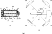
Fig. 2 illustrates the two configurations of the device. First one is the configuration just after launch of the device and the second one is a partial sketch of the final configuration moments before the encounter with the target. -
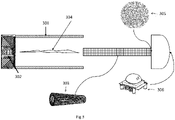
Fig. 3 illustrates the details of the mechanical/artificial intelligence operated trigger mechanism of the device. -
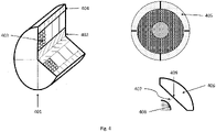
Fig. 4 illustrates the details of one segment of the device. -
Fig 5 contains the table with the characteristics and performance of the system for the different configurations. - In cooperation with attached drawings, the technical contents and detailed description of the present invention are described thereinafter according to a preferable embodiment, being not used to limit its executing scope. Any equivalent variation and modification made according to appended claims is all covered by the claims claimed by the present invention.
- Reference will now be made to the drawing figures to describe the present invention in detail.
- Reference is made to
Fig. 1 and the different elements of the system. - The launchers elements of the system are represented at 101,102,103, and 104. These elements go from the most powerful 101 limited to high end military market to the one focused on private/
individual markets 104. In the 101 numeral is depicted an automatic grenade launcher capable to shot 200 till 450 rounds per minute and an effective range of 1500 metres. This machine is restricted for military use and has additional support of advance automated tracking and shutting capabilities. It can handle swarms of hundreds of drones without problem. -
Numeral 102 presents a handheld grenade launcher also capable to shoot a few rounds automatically. Also focused on the military and defence operations it is capable to achieve targets at distances till 500 metres. -
Numeral 103 is an equipment that is standard use in the police and security forces worldwide. The shooting is made one by one round and the range could reach 150 metres. -
Numeral 104 is a working/plastic replica of the 103 element that could be used in domestic markets. Maximum range of these launchers is in the order of 30 metres. The propulsion elements are depicted at 105, 106, 107, and 108. -
Numeral 105 represents a high velocity and 106 a low velocity, point initiating, base detonating fuse propulsion grenade to be used withelements -
Numeral 106 depicts a low velocity propulsion for use with the 103 elements with initial speed of 78-84 m/s. -
Numeral 107 is the propulsion system for use with 104 element that achieves initial speeds of 25-35 m/s by means of soft air impulsion. - All the above-mentioned elements are manufactured, and patent protected by several manufacturers and patents worldwide and are incorporated at the present invention only as a matter of reference.
- The device object of the present invention is depicted in
numeral 109 in the moment that is initiating the flight towards the target. The target is represented atnumeral 110. The device element is shown in more detailed atFig 2 . - The
initial configuration 201 of the device comprisesseveral segments 202. The minimum number of segments are two for the 104/107 element, and the standard configurations for low and high velocity propulsion elements are four and six segments, respectively. Each segment is made of fourpieces 203 each at 90 degrees that conforms the cylinder surface and are maintained together initially by the external container of thedevice 204. They exercise a pressure to the container by means of pressurized gas/spring mechanisms. Each piece is an aerodynamic surface that at launch time are arranged in the cylinder form. - The inner part of each segment is occupied by a
coiled wire 205 that joins each of the aerodynamic surfaces with the axe of the device. The reels of the wire can turn freely around the axe of thedevice 206. The axe is attached to the ogive of thedevice 207. Within the ogive are contained the electronic boards with the appropriate sensors andcircuits 208. - The ogive seats initially at the external surface of the
device 209. - The trigger mechanism that liberates the ogive, axe and internal surface from the external part joining with the base of the
device 210 are depicted in 211, 212, and 213. Spinning of the device is achieved at launch time exiting from the launcher tube by means of 214. -
Numeral 215 represents the join of the device with the launch projection element. - The device is launched at a spin condition of 3600 rpm and near the target a trigger signal detach the external part of the device by means of 211, 212 and 213 and the elastic forces that maintained jointly the surfaces are liberated and the wires start to unroll.
- Final configuration, as depicted in
numeral 216 for onesegment 217, shows the foursurfaces 218 spinning attached to the full length of thewires 219 and conserving the kinetic momentum of the initial configuration. (The figure is not at scale). - The interaction of any of the wires with the drone will trigger the transfer of the combined kinetic momentum and linear momentum of the device to the target disrupting its flying conditions and pushing it to earth.
- The transformation of the configuration of the device is trigged by an automated mechanical time delay mechanism or an artificial intelligence operated mechanism contained in the ogive of the device. First one is used with the
elements elements - The objective is that the device must be fully deployed in a range of 10-30 metres to the target.
- Deployment time will take less than one second.
- Reference is made to
figure 3 that shows the arrangements for the mechanical/artificial intelligence operated trigger mechanism. -
Numeral 301 refers to the external part of the device that has no more intervention in the capture process after separation. -
Numeral 302 is the join reference tonumerals figure 2 . - Electrical power of the system in the configurations that is needed is contained within the axe of the device pictured in 303. The axe also contains the
communication mechanism 304 that transfer the signals from the ogive place electronics to the trigger mechanism. The trigger mechanism for the bottom of the game devices will be simply a mechanical arrangement that at the time of launch will also trigger the expulsion of the internal part of the device with or without a prescheduled time delay. - For the
devices 103/107 offigure 1 and up, electronic boards with different sensors will be mounted of the device to achieve a final deployment between 10 - 30 metres to the target. - The numeral 305 refers a stack containing a microphone as sensor that allow determinate the distance by kind of sonar artificial intelligence model and numeral 306 pictured a passive infrared radar sensor that will be mounted at the tip of the ogive (infrared radome type). Any other sensor will be also considered for advanced strategies of deployment.
- Reference is made to
figure 4 which presents the details of onesegment 401 showing one of the surfaces detached. They are depicted sections of theaxe 402, the four coils containing the wires rolled with the detailed wires of one of them 403, and theaerodynamic surface 404. The coils will turn freely around the axe of the ogive and base composite of the device. -
Numeral 405 shows the surfaces before the deployment and 406 after the deployment. The deployment of the aerodynamic surfaces is achieved not only by the action of the centripetal forces nor by the compressed air/springs which fill the surfaces, once they liberated due to the expulsion of the external cover at the signal trigger time. - The
wires 407 are attached to thering 408 that turns freely around the axe and to the middle of thesurface 409. The elements off the picture are not at scale. - The length of the wires as well as the material composition of them will varied accordingly with the target and the rest of the elements of the system.
- Normalized lengths of the wires will be 2,5 meters for the bottom of the game systems to 6 metres for the top of the game. The materials of the wire will be from nylon wires for the bottom of the game to strong metals for the top of the game. Diameters of the wired will also varied from 0.25 to 1 millimetre.
- The table at
figure 5 presents the overall characteristics of the system for all the different configurations. - The fourth column reflects the initial and final angular speeds, and in the fifth column degrees refers to the separation between adjacent wires.
- While the invention may have been described with reference to certain embodiments, numerous changes, alterations, and modifications to the described embodiments are possible without departing from the spirit and scope of the invention as defined in the appended claims, and equivalents thereof.
Claims (10)
- A device launched by means of a propulsion element that targets a micro or small unmanned aerial vehicle and by means of projecting its kinetic and linear momentum to the target disrupts its flying configuration and push it to the earth,said device including an ogive and axe section which contains the battery and electronic equipment,said device including aerodynamic parts that are deployed by means of elastic and centripetal forces at a time stablished with a prescheduled delay or triggered by smart sensors electronic signalling,said device including wires that join the aerodynamic surfaces to the axe of the body device,said wires turning freely around the axe in conjunction with the aerodynamic surfaces and transferring the kinetic and linear momentum of the device to the target.
- The device of claim 1 wherein the prescheduled delay is established in the device during manufacturing and identified by the operator with a colour table.
- The device of claim 1 wherein the smart sensors feed an artificial intelligent algorithm based on reinforcement learning to achieve the best performance triggering the deployment signal.
- The device of claim 3 that has communications with an earth operator or system to allow feedback to the device.
- The device of claim 4 that support a networking environment to counteract a swarm of targets.
- A method to disrupt a flying target using the device of claim 1, the method comprising the steps of:a) loading the device in an appropriate launching element, andb) launching the device aiming to the target, andc) deploying the device accordingly to the triggering signal.
- A short-range device of claim 1 wherein the target is a mobile object not necessarily flying.
- The device of claim 7 wherein the target is a person or a hostile mob.
- A method to disrupt a hostile person or mob using the device of claim 8, the method comprising the steps of:a) loading the device in an appropriate not harming launching element, andb) launching the device aiming to the target, andc) deploying the device at a prescheduled time after launch time.
- The device of claim 1 wherein the propulsion elements are 40 mm.
Priority Applications (1)
| Application Number | Priority Date | Filing Date | Title |
|---|---|---|---|
| EP21020025.9A EP4033197A1 (en) | 2021-01-21 | 2021-01-21 | Anti-drone device based on kinetic and linear momentum projection |
Applications Claiming Priority (1)
| Application Number | Priority Date | Filing Date | Title |
|---|---|---|---|
| EP21020025.9A EP4033197A1 (en) | 2021-01-21 | 2021-01-21 | Anti-drone device based on kinetic and linear momentum projection |
Publications (1)
| Publication Number | Publication Date |
|---|---|
| EP4033197A1 true EP4033197A1 (en) | 2022-07-27 |
Family
ID=74205608
Family Applications (1)
| Application Number | Title | Priority Date | Filing Date |
|---|---|---|---|
| EP21020025.9A Withdrawn EP4033197A1 (en) | 2021-01-21 | 2021-01-21 | Anti-drone device based on kinetic and linear momentum projection |
Country Status (1)
| Country | Link |
|---|---|
| EP (1) | EP4033197A1 (en) |
Cited By (1)
| Publication number | Priority date | Publication date | Assignee | Title |
|---|---|---|---|---|
| RU226203U1 (en) * | 2024-03-20 | 2024-05-27 | Валерий Викторович Присухин | Device for firing cartridges using an under-barrel grenade launcher |
Citations (7)
| Publication number | Priority date | Publication date | Assignee | Title |
|---|---|---|---|---|
| WO2008145328A1 (en) * | 2007-05-31 | 2008-12-04 | Rheinmetall Waffe Munition Gmbh | Catching system |
| GB2537664A (en) * | 2015-04-22 | 2016-10-26 | David Down Christopher | A system for tangling a vehicle |
| US20170261292A1 (en) * | 2016-03-12 | 2017-09-14 | Kestrel Science and Innovation, LLC | Interdiction and recovery for small unmanned aircraft systems |
| US10197365B1 (en) | 2017-10-20 | 2019-02-05 | The United States Of America As Represented By The Secretary Of The Army | Scalable effects net warhead |
| RU2680558C1 (en) * | 2017-06-16 | 2019-02-22 | Геннадий Витальевич Чередников | Method of increasing the probability of overcoming zones of missile defense |
| US20190129427A1 (en) * | 2016-07-20 | 2019-05-02 | Prodrone Co., Ltd. | Unmanned aerial vehicle and moving object capturing system |
| US20200108925A1 (en) * | 2018-10-03 | 2020-04-09 | Sarcos Corp. | Countermeasure Deployment System Facilitating Neutralization of Target Aerial Vehicles |
-
2021
- 2021-01-21 EP EP21020025.9A patent/EP4033197A1/en not_active Withdrawn
Patent Citations (7)
| Publication number | Priority date | Publication date | Assignee | Title |
|---|---|---|---|---|
| WO2008145328A1 (en) * | 2007-05-31 | 2008-12-04 | Rheinmetall Waffe Munition Gmbh | Catching system |
| GB2537664A (en) * | 2015-04-22 | 2016-10-26 | David Down Christopher | A system for tangling a vehicle |
| US20170261292A1 (en) * | 2016-03-12 | 2017-09-14 | Kestrel Science and Innovation, LLC | Interdiction and recovery for small unmanned aircraft systems |
| US20190129427A1 (en) * | 2016-07-20 | 2019-05-02 | Prodrone Co., Ltd. | Unmanned aerial vehicle and moving object capturing system |
| RU2680558C1 (en) * | 2017-06-16 | 2019-02-22 | Геннадий Витальевич Чередников | Method of increasing the probability of overcoming zones of missile defense |
| US10197365B1 (en) | 2017-10-20 | 2019-02-05 | The United States Of America As Represented By The Secretary Of The Army | Scalable effects net warhead |
| US20200108925A1 (en) * | 2018-10-03 | 2020-04-09 | Sarcos Corp. | Countermeasure Deployment System Facilitating Neutralization of Target Aerial Vehicles |
Cited By (2)
| Publication number | Priority date | Publication date | Assignee | Title |
|---|---|---|---|---|
| RU226203U1 (en) * | 2024-03-20 | 2024-05-27 | Валерий Викторович Присухин | Device for firing cartridges using an under-barrel grenade launcher |
| RU227995U1 (en) * | 2024-04-12 | 2024-08-12 | Валерий Вазгенович Георгиади | Device for firing hunting cartridges from an underbarrel grenade launcher |
Similar Documents
| Publication | Publication Date | Title |
|---|---|---|
| US11753160B2 (en) | Unmanned aerial vehicle | |
| US9074858B2 (en) | Projectile-deployed countermeasure system | |
| US6626077B1 (en) | Intercept vehicle for airborne nuclear, chemical and biological weapons of mass destruction | |
| US8205537B1 (en) | Interceptor projectile with net and tether | |
| US20220170725A1 (en) | Visual guidance system for barrel-fired projectiles | |
| US20060169832A1 (en) | Rocket propelled barrier defense system | |
| WO2018112275A1 (en) | Nets and devices for facilitating capture of unmanned aerial vehicles | |
| WO2017160750A1 (en) | Interdiction and recovery for small unmanned aircraft systems | |
| RU185949U1 (en) | DEVICE FOR UNMANNED AERIAL VEHICLES | |
| US10731950B2 (en) | Vehicle defense projectile | |
| RU2326328C2 (en) | Method for remote enemy destruction | |
| WO2022257510A1 (en) | Countering method for unmanned aerial vehicle and countering system for unmanned aerial vehicle | |
| WO2019046911A1 (en) | Unmanned aerial vehicle | |
| US20100313741A1 (en) | Applications of directional ammunition discharged from a low velocity cannon | |
| US20240077285A1 (en) | Entangling projectile system for the disabling of uav's and other targets of interest | |
| US11828573B2 (en) | Intelligent munition | |
| CN111879180A (en) | Low-altitude low-speed small target low-cost interception system and method | |
| CN212253846U (en) | Low-altitude low-speed small target low-cost interception system | |
| US5070790A (en) | Target marker to attract projectiles provided with a homing head | |
| EP4033197A1 (en) | Anti-drone device based on kinetic and linear momentum projection | |
| RU2669881C1 (en) | Unmanned system of active countermeasures of the uav | |
| RU2733600C1 (en) | Thermobaric method of swarm control of small-size unmanned aerial vehicles | |
| RU2745590C1 (en) | Method for capture of air target with a net | |
| RU2601241C2 (en) | Ac active protection method and system for its implementation (versions) | |
| Barnaby | Will there be a Nuclear War? |
Legal Events
| Date | Code | Title | Description |
|---|---|---|---|
| PUAI | Public reference made under article 153(3) epc to a published international application that has entered the european phase |
Free format text: ORIGINAL CODE: 0009012 |
|
| STAA | Information on the status of an ep patent application or granted ep patent |
Free format text: STATUS: THE APPLICATION HAS BEEN PUBLISHED |
|
| AK | Designated contracting states |
Kind code of ref document: A1 Designated state(s): AL AT BE BG CH CY CZ DE DK EE ES FI FR GB GR HR HU IE IS IT LI LT LU LV MC MK MT NL NO PL PT RO RS SE SI SK SM TR |
|
| STAA | Information on the status of an ep patent application or granted ep patent |
Free format text: STATUS: THE APPLICATION IS DEEMED TO BE WITHDRAWN |
|
| 18D | Application deemed to be withdrawn |
Effective date: 20230128 |