EP4033078A1 - Brennkraftmaschine mit nh3-sensor im abgasstrang - Google Patents
Brennkraftmaschine mit nh3-sensor im abgasstrang Download PDFInfo
- Publication number
- EP4033078A1 EP4033078A1 EP22150769.2A EP22150769A EP4033078A1 EP 4033078 A1 EP4033078 A1 EP 4033078A1 EP 22150769 A EP22150769 A EP 22150769A EP 4033078 A1 EP4033078 A1 EP 4033078A1
- Authority
- EP
- European Patent Office
- Prior art keywords
- combustion engine
- internal combustion
- catalytic converter
- way catalytic
- sensor
- Prior art date
- Legal status (The legal status is an assumption and is not a legal conclusion. Google has not performed a legal analysis and makes no representation as to the accuracy of the status listed.)
- Granted
Links
Images
Classifications
-
- F—MECHANICAL ENGINEERING; LIGHTING; HEATING; WEAPONS; BLASTING
- F01—MACHINES OR ENGINES IN GENERAL; ENGINE PLANTS IN GENERAL; STEAM ENGINES
- F01N—GAS-FLOW SILENCERS OR EXHAUST APPARATUS FOR MACHINES OR ENGINES IN GENERAL; GAS-FLOW SILENCERS OR EXHAUST APPARATUS FOR INTERNAL-COMBUSTION ENGINES
- F01N3/00—Exhaust or silencing apparatus having means for purifying, rendering innocuous, or otherwise treating exhaust
- F01N3/08—Exhaust or silencing apparatus having means for purifying, rendering innocuous, or otherwise treating exhaust for rendering innocuous
- F01N3/10—Exhaust or silencing apparatus having means for purifying, rendering innocuous, or otherwise treating exhaust for rendering innocuous by thermal or catalytic conversion of noxious components of exhaust
- F01N3/101—Three-way catalysts
-
- F—MECHANICAL ENGINEERING; LIGHTING; HEATING; WEAPONS; BLASTING
- F01—MACHINES OR ENGINES IN GENERAL; ENGINE PLANTS IN GENERAL; STEAM ENGINES
- F01N—GAS-FLOW SILENCERS OR EXHAUST APPARATUS FOR MACHINES OR ENGINES IN GENERAL; GAS-FLOW SILENCERS OR EXHAUST APPARATUS FOR INTERNAL-COMBUSTION ENGINES
- F01N13/00—Exhaust or silencing apparatus characterised by constructional features
- F01N13/009—Exhaust or silencing apparatus characterised by constructional features having two or more separate purifying devices arranged in series
- F01N13/0093—Exhaust or silencing apparatus characterised by constructional features having two or more separate purifying devices arranged in series the purifying devices are of the same type
-
- F—MECHANICAL ENGINEERING; LIGHTING; HEATING; WEAPONS; BLASTING
- F01—MACHINES OR ENGINES IN GENERAL; ENGINE PLANTS IN GENERAL; STEAM ENGINES
- F01N—GAS-FLOW SILENCERS OR EXHAUST APPARATUS FOR MACHINES OR ENGINES IN GENERAL; GAS-FLOW SILENCERS OR EXHAUST APPARATUS FOR INTERNAL-COMBUSTION ENGINES
- F01N9/00—Electrical control of exhaust gas treating apparatus
-
- F—MECHANICAL ENGINEERING; LIGHTING; HEATING; WEAPONS; BLASTING
- F01—MACHINES OR ENGINES IN GENERAL; ENGINE PLANTS IN GENERAL; STEAM ENGINES
- F01N—GAS-FLOW SILENCERS OR EXHAUST APPARATUS FOR MACHINES OR ENGINES IN GENERAL; GAS-FLOW SILENCERS OR EXHAUST APPARATUS FOR INTERNAL-COMBUSTION ENGINES
- F01N2430/00—Influencing exhaust purification, e.g. starting of catalytic reaction, filter regeneration, or the like, by controlling engine operating characteristics
- F01N2430/06—Influencing exhaust purification, e.g. starting of catalytic reaction, filter regeneration, or the like, by controlling engine operating characteristics by varying fuel-air ratio, e.g. by enriching fuel-air mixture
-
- F—MECHANICAL ENGINEERING; LIGHTING; HEATING; WEAPONS; BLASTING
- F01—MACHINES OR ENGINES IN GENERAL; ENGINE PLANTS IN GENERAL; STEAM ENGINES
- F01N—GAS-FLOW SILENCERS OR EXHAUST APPARATUS FOR MACHINES OR ENGINES IN GENERAL; GAS-FLOW SILENCERS OR EXHAUST APPARATUS FOR INTERNAL-COMBUSTION ENGINES
- F01N2560/00—Exhaust systems with means for detecting or measuring exhaust gas components or characteristics
- F01N2560/02—Exhaust systems with means for detecting or measuring exhaust gas components or characteristics the means being an exhaust gas sensor
- F01N2560/021—Exhaust systems with means for detecting or measuring exhaust gas components or characteristics the means being an exhaust gas sensor for measuring or detecting ammonia NH3
-
- F—MECHANICAL ENGINEERING; LIGHTING; HEATING; WEAPONS; BLASTING
- F01—MACHINES OR ENGINES IN GENERAL; ENGINE PLANTS IN GENERAL; STEAM ENGINES
- F01N—GAS-FLOW SILENCERS OR EXHAUST APPARATUS FOR MACHINES OR ENGINES IN GENERAL; GAS-FLOW SILENCERS OR EXHAUST APPARATUS FOR INTERNAL-COMBUSTION ENGINES
- F01N2560/00—Exhaust systems with means for detecting or measuring exhaust gas components or characteristics
- F01N2560/02—Exhaust systems with means for detecting or measuring exhaust gas components or characteristics the means being an exhaust gas sensor
- F01N2560/025—Exhaust systems with means for detecting or measuring exhaust gas components or characteristics the means being an exhaust gas sensor for measuring or detecting O2, e.g. lambda sensors
-
- F—MECHANICAL ENGINEERING; LIGHTING; HEATING; WEAPONS; BLASTING
- F01—MACHINES OR ENGINES IN GENERAL; ENGINE PLANTS IN GENERAL; STEAM ENGINES
- F01N—GAS-FLOW SILENCERS OR EXHAUST APPARATUS FOR MACHINES OR ENGINES IN GENERAL; GAS-FLOW SILENCERS OR EXHAUST APPARATUS FOR INTERNAL-COMBUSTION ENGINES
- F01N2560/00—Exhaust systems with means for detecting or measuring exhaust gas components or characteristics
- F01N2560/14—Exhaust systems with means for detecting or measuring exhaust gas components or characteristics having more than one sensor of one kind
-
- F—MECHANICAL ENGINEERING; LIGHTING; HEATING; WEAPONS; BLASTING
- F01—MACHINES OR ENGINES IN GENERAL; ENGINE PLANTS IN GENERAL; STEAM ENGINES
- F01N—GAS-FLOW SILENCERS OR EXHAUST APPARATUS FOR MACHINES OR ENGINES IN GENERAL; GAS-FLOW SILENCERS OR EXHAUST APPARATUS FOR INTERNAL-COMBUSTION ENGINES
- F01N2570/00—Exhaust treating apparatus eliminating, absorbing or adsorbing specific elements or compounds
- F01N2570/14—Nitrogen oxides
- F01N2570/145—Dinitrogen oxide
-
- F—MECHANICAL ENGINEERING; LIGHTING; HEATING; WEAPONS; BLASTING
- F01—MACHINES OR ENGINES IN GENERAL; ENGINE PLANTS IN GENERAL; STEAM ENGINES
- F01N—GAS-FLOW SILENCERS OR EXHAUST APPARATUS FOR MACHINES OR ENGINES IN GENERAL; GAS-FLOW SILENCERS OR EXHAUST APPARATUS FOR INTERNAL-COMBUSTION ENGINES
- F01N2570/00—Exhaust treating apparatus eliminating, absorbing or adsorbing specific elements or compounds
- F01N2570/18—Ammonia
-
- F—MECHANICAL ENGINEERING; LIGHTING; HEATING; WEAPONS; BLASTING
- F01—MACHINES OR ENGINES IN GENERAL; ENGINE PLANTS IN GENERAL; STEAM ENGINES
- F01N—GAS-FLOW SILENCERS OR EXHAUST APPARATUS FOR MACHINES OR ENGINES IN GENERAL; GAS-FLOW SILENCERS OR EXHAUST APPARATUS FOR INTERNAL-COMBUSTION ENGINES
- F01N2900/00—Details of electrical control or of the monitoring of the exhaust gas treating apparatus
- F01N2900/04—Methods of control or diagnosing
- F01N2900/0416—Methods of control or diagnosing using the state of a sensor, e.g. of an exhaust gas sensor
-
- F—MECHANICAL ENGINEERING; LIGHTING; HEATING; WEAPONS; BLASTING
- F01—MACHINES OR ENGINES IN GENERAL; ENGINE PLANTS IN GENERAL; STEAM ENGINES
- F01N—GAS-FLOW SILENCERS OR EXHAUST APPARATUS FOR MACHINES OR ENGINES IN GENERAL; GAS-FLOW SILENCERS OR EXHAUST APPARATUS FOR INTERNAL-COMBUSTION ENGINES
- F01N2900/00—Details of electrical control or of the monitoring of the exhaust gas treating apparatus
- F01N2900/06—Parameters used for exhaust control or diagnosing
- F01N2900/14—Parameters used for exhaust control or diagnosing said parameters being related to the exhaust gas
- F01N2900/1402—Exhaust gas composition
-
- F—MECHANICAL ENGINEERING; LIGHTING; HEATING; WEAPONS; BLASTING
- F01—MACHINES OR ENGINES IN GENERAL; ENGINE PLANTS IN GENERAL; STEAM ENGINES
- F01N—GAS-FLOW SILENCERS OR EXHAUST APPARATUS FOR MACHINES OR ENGINES IN GENERAL; GAS-FLOW SILENCERS OR EXHAUST APPARATUS FOR INTERNAL-COMBUSTION ENGINES
- F01N2900/00—Details of electrical control or of the monitoring of the exhaust gas treating apparatus
- F01N2900/06—Parameters used for exhaust control or diagnosing
- F01N2900/16—Parameters used for exhaust control or diagnosing said parameters being related to the exhaust apparatus, e.g. particulate filter or catalyst
- F01N2900/1616—NH3-slip from catalyst
-
- F—MECHANICAL ENGINEERING; LIGHTING; HEATING; WEAPONS; BLASTING
- F01—MACHINES OR ENGINES IN GENERAL; ENGINE PLANTS IN GENERAL; STEAM ENGINES
- F01N—GAS-FLOW SILENCERS OR EXHAUST APPARATUS FOR MACHINES OR ENGINES IN GENERAL; GAS-FLOW SILENCERS OR EXHAUST APPARATUS FOR INTERNAL-COMBUSTION ENGINES
- F01N3/00—Exhaust or silencing apparatus having means for purifying, rendering innocuous, or otherwise treating exhaust
- F01N3/02—Exhaust or silencing apparatus having means for purifying, rendering innocuous, or otherwise treating exhaust for cooling, or for removing solid constituents of, exhaust
- F01N3/021—Exhaust or silencing apparatus having means for purifying, rendering innocuous, or otherwise treating exhaust for cooling, or for removing solid constituents of, exhaust by means of filters
- F01N3/033—Exhaust or silencing apparatus having means for purifying, rendering innocuous, or otherwise treating exhaust for cooling, or for removing solid constituents of, exhaust by means of filters in combination with other devices
- F01N3/035—Exhaust or silencing apparatus having means for purifying, rendering innocuous, or otherwise treating exhaust for cooling, or for removing solid constituents of, exhaust by means of filters in combination with other devices with catalytic reactors
Definitions
- the invention relates to an internal combustion engine and a method for operating such an internal combustion engine.
- the control of the mass ratio of the air and fuel components of a mixture that is fed to the internal combustion engine of an internal combustion engine for combustion is not only of central importance for the operation of the internal combustion engine but also for after-treatment of exhaust gas generated by the internal combustion engine.
- This mass ratio is usually described with the dimensionless characteristic number ⁇ (lambda), which is also referred to as the combustion air ratio.
- the combustion air ratio specifically indicates the mass ratio of the mixture components air and fuel relative to the stoichiometrically ideal mass ratio for a theoretically complete combustion process.
- Gasoline engines that are spark-ignited and quantity-controlled are often operated with a fundamentally stoichiometric air-combustion ratio, i.e. with ⁇ ⁇ 1.
- a fundamentally stoichiometric air-combustion ratio i.e. with ⁇ ⁇ 1.
- the residual oxygen content in the exhaust gas is analyzed using a so-called lambda probe and the air-fuel mass ratio is controlled for subsequent combustion processes is used.
- Such a reactive control means that the actual combustion air ratio fluctuates in a usually relatively narrow range around the stoichiometric combustion air ratio.
- it is known to actively implement a so-called natural frequency control for the combustion air ratio in which the combustion engine is defined alternately slightly rich, i.e.
- a typical configuration of an exhaust gas aftertreatment device integrated into the exhaust line of a spark-ignition engine comprises, viewed in the flow direction of the exhaust gas, first a first lambda probe, then a first three-way catalytic converter, then a second lambda probe and finally a second three-way catalytic converter.
- a Three-way catalytic converter is characterized in that it converts carbon monoxide (CO), nitrogen oxides (NOx) and unburned hydrocarbons (HC) into carbon dioxide (CO 2 ), nitrogen (N 2 ) and water (H 2 O).
- CO 2 carbon dioxide
- NOx nitrogen oxides
- HC unburned hydrocarbons
- CO 2 carbon dioxide
- N 2 nitrogen
- H 2 O water
- such a three-way catalytic converter usually also has what is known as an oxygen storage capacity. As a result, it can store oxygen to a limited extent.
- the U.S. 7,003,943 B2 discloses a method for the controlled adjustment of the air/fuel ratio ⁇ in an internal combustion engine by means of an NOx sensor, which is intended to replace the two lambda sensors that are otherwise customary.
- the U.S. 10,598,063 B2 discloses a method for functional testing of a three-way catalytic converter using a NOx sensor which is arranged downstream of the three-way catalytic converter.
- the U.S. 9,115,660 B2 discloses an internal combustion engine with an internal combustion engine and an exhaust system in which a three-way catalytic converter, an NOx storage catalytic converter, an SCR catalytic converter and an NOx sensor are integrated, viewed in the flow direction of the exhaust gas.
- the object of the invention was to avoid as far as possible the formation of ammonia and nitrous oxide in the exhaust gas of an internal combustion engine.
- an internal combustion engine according to claim 1 which can be operated according to a method which is the subject of claim 7.
- Advantageous embodiments of the internal combustion engine according to the invention and preferred embodiments of the method according to the invention are the subject of the further patent claims and/or result from the following description of the invention.
- an internal combustion engine which comprises at least one internal combustion engine and an exhaust system.
- the internal combustion engine is preferably spark-ignited at least at times and can also preferably be operated in a quantity-regulated manner (ie then as an Otto engine).
- a (first) lambda probe, then a first three-way catalytic converter and then a second three-way catalytic converter are integrated into the exhaust line, viewed in the flow direction of the exhaust gas, ie starting from the internal combustion engine.
- an NH 3 sensor ie a sensor by means of which ammonia can be determined directly or indirectly, is also integrated in the exhaust line between the first three-way catalytic converter and the second three-way catalytic converter.
- Switching from lean operation to rich operation can preferably take place within the scope of a method according to the invention when a defined Presence (ie a fundamentally determinable presence or presence in a defined minimum amount) of oxygen in the exhaust gas downstream of the first three-way catalyst (and preferably upstream of the second three-way catalyst) is determined.
- the presence of oxygen in the exhaust gas can be determined in a basically known manner by means of a second lambda probe, which is integrated in the exhaust line between the first three-way catalytic converter and the second three-way catalytic converter.
- an NOx sensor ie a sensor by means of which at least nitrogen oxides can also be determined directly or indirectly, can also be arranged in this section of the exhaust line for this purpose.
- Such a NOx sensor can also advantageously be designed integrally with the NH 3 sensor, ie as an NH 3 -NOx combination sensor.
- At least one particle filter can also be integrated into the exhaust line in order to minimize emission of particles with the exhaust gas.
- a particle filter can be assigned to the first three-way catalytic converter and/or the second three-way catalytic converter, with integration into the respective three-way catalytic converter (to form a so-called four-way catalytic converter) or the arrangement downstream, in particular immediately downstream of it (and with regard to the first three-way catalytic converter upstream of the second three-way catalyst) is understood.
- a particle filter is provided with a coating that acts as a three-way catalytic converter.
- the first lambda probe is designed as a broadband lambda probe, whereby high control accuracy for the basic control of the air/fuel ratio can be achieved by means of the first lambda probe.
- the second lambda probe that may be present can advantageously be configured as a jump lambda probe (also known as a two-point lambda probe), as a result of which the incipient presence of oxygen in the exhaust gas can be determined relatively quickly and accurately.
- the first lambda probe can also be configured as a jump lambda probe.
- the internal combustion engine of an internal combustion engine according to the invention can preferably be operated with liquid fuel (ie in particular gasoline). Operation with a gaseous fuel (in particular natural gas, LNG or LPG) is also possible.
- liquid fuel ie in particular gasoline
- gaseous fuel in particular natural gas, LNG or LPG
- the invention also relates to a motor vehicle, in particular a wheel-based and non-rail-bound motor vehicle (preferably a car or a truck), with an internal combustion engine according to the invention.
- a motor vehicle in particular a wheel-based and non-rail-bound motor vehicle (preferably a car or a truck), with an internal combustion engine according to the invention.
- the internal combustion engine of the internal combustion engine can be provided in particular for the (direct or indirect) provision of the driving power for the motor vehicle.
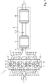
- the 1 shows an internal combustion engine for a motor vehicle according to the invention and thus also suitable for carrying out a method according to the invention.
- This comprises an internal combustion engine 1, which is designed, for example, in the form of a reciprocating piston engine with four cylinder openings 2 arranged in a row.
- the cylinder openings 2 delimit a combustion chamber 4 with reciprocating pistons 3 guided therein and a cylinder head.
- these combustion chambers 4 are supplied with fresh gas via a fresh gas line 5, with the fresh gas being supplied by means of inlet valves 9, which are connected to the individual combustion chambers 4 are assigned is controlled.
- the fresh gas is exclusively or mainly air that is sucked in from the environment.
- Exhaust gas that is produced during the combustion of mixture quantities which consists of the fresh gas and fuel injected directly into the combustion chambers 4 via fuel injectors 6, is discharged via an exhaust line 7 of the internal combustion engine, with the exhaust gas being discharged by means of outlet valves 10, which control the individual Combustion chambers 4 are assigned, is controlled.
- the quantities of mixture in the combustion chambers are ignited by means of electrical ignition devices 16 which, for example, generate ignition sparks (spark plugs).
- the exhaust gas flows through an exhaust gas after-treatment device 8, which is intended to remove components of the exhaust gas that are regarded as pollutants from the exhaust gas or to convert them into harmless components.
- the internal combustion engine can be supercharged, in which case a fresh-gas compressor (not shown) would then be integrated into the fresh-gas line 5 .
- this exhaust-gas turbocharger would also include an exhaust-gas turbine (not shown), which is integrated into the exhaust line. Exhaust gas that flows through the exhaust gas turbine then leads to a rotating drive of a turbine impeller, which is rotationally drivingly connected to a compressor impeller of the fresh gas compressor, so that as a result the fresh gas compressor is driven by the exhaust gas turbine.
- the exhaust gas aftertreatment device 8 of the internal combustion engine comprises, seen in the direction of flow of the exhaust gas, a first lambda probe 11, preferably configured as a broadband lambda probe, then a first three-way catalytic converter 12, which can optionally be configured as a four-way catalytic converter and can therefore also include a particle filter, then an NOx sensor 13 and an NH 3 sensor 14, which is designed in the form of an NH 3 -NO x combination sensor, and finally a second three-way catalytic converter 15, which can also optionally be designed as a four-way catalytic converter.
- the fresh gas to be supplied to the internal combustion engine 1 and the quantities of fuel to be introduced into the individual combustion chambers 4 by means of the fuel injectors 6 per working cycle are specifically set.
- the operating position of a throttle valve (not shown) integrated in the fresh-gas line 5 and/or a variable valve drive (not shown), by means of which the inlet valves 9 can be variably actuated can be changed with regard to the fresh gas.
- the internal combustion engine is at least temporarily operated stoichiometrically ( ⁇ 1) on average, so that the oxygen supplied to the combustion chambers 4 essentially corresponds exactly to the quantity over this period of time that is currently required for thermal conversion of the fuel supplied at the same time. Since constant stoichiometric operation of the internal combustion engine cannot be implemented in terms of control technology, internal combustion engine 1 is alternately operated slightly rich and slightly lean in such a way that stoichiometric operation is set on average over the period under consideration.
- a changeover from rich operation to lean operation of the internal combustion engine 1 takes place when a defined presence of ammonia in the exhaust gas is determined by means of the NH 3 sensor 14 .
- Such a presence of ammonia in the exhaust gas is due to the fact that rich breakthroughs occur in the first three-way catalyst 12 because unburned hydrocarbons that are contained in the raw exhaust gas during rich operation are no longer largely fully utilized in the first three-way catalyst 12 stored oxygen can be converted.
- the direct determination of ammonia by means of the NH 3 sensor 14 and the use of such a determination for defining the point in time for switching from rich operation to lean operation of the internal combustion engine 1 means that rich breakthroughs occur as quickly as possible during operation of the internal combustion engine 1 are detected and this is counteracted by switching to a lean operation of the internal combustion engine 1, since the presence of unburned hydrocarbons in the raw exhaust gas is largely avoided in the lean operation. Furthermore, in a lean operation of the internal combustion engine 1 , oxygen contained in the raw exhaust gas is stored in an oxygen storage capacity of the first three-way catalyst 12 . As a result, oxygen is again available in first three-way catalytic converter 12 for conversion of unburned hydrocarbons during subsequent rich operation of internal combustion engine 1 .
- Such a switchover from lean operation to rich operation takes place when a defined presence of oxygen in the exhaust gas downstream of the first three-way catalytic converter 12 is determined by means of the NOx sensor 13, this presence of oxygen in the exhaust gas being due to the fact that the oxygen storage capacity of the first three-way catalytic converter 12 is essentially completely filled.
- the formation of ammonia and, via the ammonia, of nitrous oxide in the first three-way catalytic converter 12 can be minimized in a relatively simple manner by regulating the combustion air ratio during operation of the internal combustion engine 1 according to the invention.
Landscapes
- Engineering & Computer Science (AREA)
- Chemical & Material Sciences (AREA)
- Combustion & Propulsion (AREA)
- Mechanical Engineering (AREA)
- General Engineering & Computer Science (AREA)
- Materials Engineering (AREA)
- Health & Medical Sciences (AREA)
- Chemical Kinetics & Catalysis (AREA)
- Toxicology (AREA)
- Electrical Control Of Air Or Fuel Supplied To Internal-Combustion Engine (AREA)
- Investigating Or Analyzing Materials By The Use Of Fluid Adsorption Or Reactions (AREA)
- Exhaust Gas After Treatment (AREA)
Abstract
Description
- Die Erfindung betrifft eine Brennkraftmaschine sowie ein Verfahren zum Betreiben einer solchen Brennkraftmaschine.
- Die Regelung des Massenverhältnisses der Bestandteile Luft und Brennstoff eines Gemischs, das dem Verbrennungsmotor einer Brennkraftmaschine zur Verbrennung zugeführt wird, ist nicht nur von zentraler Bedeutung für den Betrieb des Verbrennungsmotors sondern auch für eine Nachbehandlung von Abgas, das von dem Verbrennungsmotor erzeugt wird. Dabei wird dieses Massenverhältnis üblicherweise mit der dimensionslosen Kennzahl λ (Lambda), die auch als Verbrennungsluftverhältnis bezeichnet wird, beschrieben. Das Verbrennungsluftverhältnis gibt dabei konkret das Massenverhältnis der Gemischbestandteile Luft und Brennstoff relativ zum stöchiometrisch idealen Massenverhältnis für einen theoretisch vollständigen Verbrennungsprozess an.
- Ottomotoren, die fremdgezündet und quantitätsgeregelt sind, werden häufig mit einem grundsätzlich stöchiometrischen Verbrennungsluftverhältnis, d.h. mit λ ≈ 1, betrieben, wobei zur Realisierung eines solchen stöchiometrischen Verbrennungsluftverhältnisses mittels einer sogenannten Lambdasonde der Restsauerstoffgehalt im Abgas analysiert und zur Regelung des Luft-Brennstoff-Massenverhältnisses für anschließende Verbrennungsprozesse genutzt wird. Eine solche reaktive Regelung führt dazu, dass das tatsächliche Verbrennungsluftverhältnis in einem üblicherweise relativ schmalen Bereich um das stöchiometrische Verbrennungsluftverhältnis schwankt. Bekannt ist diesbezüglich, aktiv eine sogenannte Eigenfrequenzregelung für das Verbrennungsluftverhältnis umzusetzen, bei der der Verbrennungsmotor definiert wechselweise leicht fett, d.h. mit einem geringfügig unterstöchiometrischen Verbrennungsluftverhältnis (λ < 1), sowie leicht mager, d.h. mit einem geringfügig überstöchiometrischen Verbrennungsluftverhältnis (λ > 1), betrieben wird. Eine Umschaltung zwischen fettem und magerem Betrieb erfolgt dabei bei definierten Abweichungen von dem stöchiometrischen Verbrennungsluftverhältnis.
- Eine übliche Ausgestaltung einer in den Abgasstrang eines Ottomotors integrierten Abgasnachbehandlungseinrichtung umfasst in Strömungsrichtung des Abgases gesehen zunächst eine erste Lambdasonde, dann einen ersten Dreiwegekatalysator, anschließend eine zweite Lambdasonde und schließlich einen zweiten Dreiwegekatalysator. Ein Dreiwegekatalysator ist dadurch gekennzeichnet, dass dieser Kohlenstoffmonoxid (CO), Stickoxide (NOx) und unverbrannte Kohlenwasserstoffe (HC) zu Kohlenstoffdioxid (CO2), Stickstoff (N2) und Wasser (H2O) umwandelt. Zudem weist ein solcher Dreiwegekatalysator üblicherweise auch eine sogenannte Sauerstoffspeicherkapazität auf. Dieser kann folglich Sauerstoff in einem begrenzten Umfang einlagern. In einem mageren Betrieb des Verbrennungsmotors einer Brennkraftmaschine, die eine solche Abgasnachbehandlungseinrichtung umfasst, wird überschüssiger, in dem Rohabgas enthaltener Sauerstoff in dem ersten Dreiwegekatalysator eingelagert, während in einem fetten Betrieb der eingelagerte Sauerstoff für die genannten Umwandlungen genutzt wird. Wenn während eines solchen fetten Betriebs des Verbrennungsmotors die Sauerstoffspeicherkapazität nahezu vollständig ausgeräumt ist, kann es zu Fettdurchbrüchen in dem ersten Dreiwegekatalysator kommen, d.h. in dem ersten Dreiwegekatalysator liegen relevante Mengen von unverbrannten Kohlenwasserstoffen vor, die nicht umgewandelt werden können, was zur Ausbildung von Ammoniak (NH3) und, über das Ammoniak, zur Bildung von Lachgas (N2O) führen kann. Eine solche Ausbildung von Ammoniak und Lachgas soll nach Möglichkeit vermieden werden.
- Die
US 7 003 943 B2 offenbart ein Verfahren zur geregelten Einstellung des Verbrennungsluftverhältnisses λ bei einem Verbrennungsmotor mittels eines NOx-Sensors, der die ansonsten üblichen zwei Lambdasensoren ersetzen soll. - Die
US 10 598 063 B2 - Die
US 9 115 660 B2 - Der Erfindung lag die Aufgabe zugrunde, eine Ausbildung von Ammoniak und Lachgas in dem Abgas einer Brennkraftmaschine möglichst zu vermieden.
- Zur Lösung dieser Aufgabe ist eine Brennkraftmaschine gemäß dem Patentanspruch 1 vorgesehen, die gemäß einem Verfahren betrieben werden kann, das Gegenstand des Patentanspruchs 7 ist. Vorteilhafte Ausgestaltungsformen der erfindungsgemäßen Brennkraftmaschine und bevorzugte Ausführungsformen des erfindungsgemäßen Verfahrens sind Gegenstände der weiteren Patentansprüche und/oder ergeben sich aus der nachfolgenden Beschreibung der Erfindung.
- Erfindungsgemäß ist eine Brennkraftmaschine vorgesehen, die zumindest einen Verbrennungsmotor und einen Abgasstrang umfasst. Der Verbrennungsmotor ist vorzugsweise zumindest zeitweise fremdgezündet und weiterhin vorzugsweise auch quantitätsgeregelt betreibbar (d.h. dann als Ottomotor) ausgestaltet. In den Abgasstrang sind in Strömungsrichtung des Abgases gesehen, d.h. ausgehend von dem Verbrennungsmotor eine (erste) Lambdasonde, dann ein erster Dreiwegekatalysator und anschließend ein zweiter Dreiwegekatalysator integriert. Erfindungsgemäß ist weiterhin zwischen dem ersten Dreiwegekatalysator und dem zweiten Dreiwegekatalysator ein NH3-Sensor, d.h. ein Sensor, mittels dessen Ammoniak direkt oder indirekt ermittelt werden kann, in den Abgasstrang integriert.
- Eine solche Brennkraftmaschine ermöglicht die Durchführung eines erfindungsgemäßen Verfahrens, gemäß dem der Verbrennungsmotor im Betrieb der Brennkraftmaschine wechselweise (leicht) fett und (leicht) mager (dabei vorzugsweise mit definierten unveränderlichen oder veränderlichen Abweichungen von dem stöchiometrischen Verbrennungsluftverhältnis (λ = 1), beispielsweise im Bereich λ = 1 ± 0,05 oder λ = 1 ± 0,03 oder λ = 1 ± 0,01) betrieben wird, was insbesondere zur Erzielung eines im Mittel stöchiometrischen Betriebs des Verbrennungsmotors dienen kann. Dabei wird von dem fetten Betrieb zu dem mageren Betrieb umgeschaltet, wenn ein definiertes Vorhandensein (d.h. ein grundsätzlich ermittelbares Vorhandensein oder ein Vorhandensein in einer definierten Mindestmenge) von Ammoniak in dem Abgas mittels des NH3-Sensors ermittelt wird. Ein solches Ermitteln kann relativ schnell erfolgen, wodurch eine Erzeugung von Ammoniak und, über das Ammoniak, von Lachgas in dem ersten Dreiwegekatalysator minimiert werden kann, weil entsprechend früh beziehungsweise rechtzeitig in den mageren Betrieb des Verbrennungsmotors umgeschaltet wird. Dadurch steht dann ausreichend Sauerstoff in dem Rohabgas, d.h. in dem von dem Verbrennungsmotor erzeugten und noch nicht nachbehandelten Abgas (stromauf des ersten Dreiwegekatalysators), zur Verfügung, um weitere Fettdurchbrüche in dem ersten Dreiwegekatalysator zu vermeiden. Eine entsprechende Regelung des Verbrennungsluftverhältnisses kann dabei deutlich schneller sein, als wenn ein Umschalten von dem fetten Betrieb zu dem mageren Betrieb basierend auf dem Signal einer Lambdasonde ermittelt würde, wie dies gemäß dem Stand der Technik vorgesehen sein kann.
- Ein Umschalten von dem mageren Betrieb zu dem fetten Betrieb kann im Rahmen eines erfindungsgemäßen Verfahrens vorzugsweise dann erfolgen, wenn ein definiertes Vorhandensein (d.h. ein grundsätzlich ermittelbares Vorhandensein oder ein Vorhandensein in einer definierten Mindestmenge) von Sauerstoff in dem Abgas stromab des ersten Dreiwegekatalysators (und vorzugsweise stromauf des zweiten Dreiwegekatalysators) ermittelt wird. Das Vorhandensein von Sauerstoff in dem Abgas kann dabei in grundsätzlich bekannter Weise mittels einer zweiten Lambdasonde ermittelt werden, die zwischen dem ersten Dreiwegekatalysator und dem zweiten Dreiwegekatalysator in den Abgasstrang integriert ist. Alternativ oder ergänzend kann für diesen Zweck auch ein NOx-Sensor, d.h. ein Sensor, mittels dessen zumindest auch Stickoxide direkt oder indirekt ermittelt werden können, in diesem Abschnitt des Abgasstrangs angeordnet sein. Ein solcher NOx-Sensor kann dabei auch in vorteilhafter Weise mit dem NH3-Sensor integral, d.h. als NH3-NOx-Kombinationssensor ausgestaltet sein.
- Gemäß einer bevorzugten Ausgestaltungsform einer erfindungsgemäßen Brennkraftmaschine kann in den Abgasstrang weiterhin mindestens ein Partikelfilter integriert sein, um eine Emission von Partikeln mit dem Abgas zu minimieren. Ein solcher Partikelfilter kann dabei dem ersten Dreiwegekatalysator und/oder dem zweiten Dreiwegekatalysator zugeordnet sein, wobei als Zuordnung die Integration in den jeweiligen Dreiwegekatalysator (zur Ausbildung eines sogenannten Vierwegekatalysators) oder die Anordnung stromab, insbesondere unmittelbar stromab davon (und hinsichtlich des ersten Dreiwegekatalysators stromauf des zweiten Dreiwegekatalysators) verstanden wird. Für die Ausbildung eines Vierwegekatalysators kann dabei vorzugsweise vorgesehen sein, dass ein Partikelfilter mit einer als Dreiwegekatalysator wirkenden Beschichtung versehen ist.
- Gemäß einer vorteilhaften Ausgestaltungsform einer erfindungsgemäßen Brennkraftmaschine kann vorgesehen sein, dass die erste Lambdasonde als Breitbandlambdasonde ausgestaltet ist, wodurch eine hohe Regelgenauigkeit für die Basisregelung des Verbrennungsluftverhältnisses mittels der ersten Lambdasonde realisiert werden kann. Die gegebenenfalls vorhandene zweite Lambdasonde kann dagegen vorteilhaft als Sprunglambdasonde (auch als Zweipunktlambdasonde bekannt) ausgestaltet sein, wodurch ein beginnendes Vorhandensein von Sauerstoff in dem Abgas relativ schnell und genau ermittelt werden kann. Grundsätzlich kann jedoch auch die erste Lambdasonde als Sprunglambdasonde ausgestaltet sein.
- Der Verbrennungsmotor einer erfindungsgemäßen Brennkraftmaschine kann vorzugsweise mit Flüssigkraftstoff (d.h. insbesondere Benzin) betrieben werden. Möglich ist auch ein Betrieb mit einem gasförmigen Kraftstoff (insbesondere Erdgas, LNG oder LPG).
- Die Erfindung betrifft weiterhin ein Kraftfahrzeug, insbesondere ein radbasiertes und nicht schienengebundenes Kraftfahrzeug (vorzugsweise ein PKW oder ein LKW), mit einer erfindungsgemäßen Brennkraftmaschine. Dabei kann der Verbrennungsmotor der Brennkraftmaschine insbesondere zur (direkten oder indirekten) Bereitstellung der Fahrantriebsleistung für das Kraftfahrzeug vorgesehen sein.
- Die Erfindung wird nachfolgend anhand eines in der Zeichnung dargestellten Ausgestaltungsbeispiels näher erläutert. In der Zeichnung zeigt:
- Fig. 1:
- eine erfindungsgemäße Brennkraftmaschine in einer vereinfachten Darstellung.
- Die
Fig. 1 zeigt eine erfindungsgemäße und damit auch für die Durchführung eines erfindungsgemäßen Verfahrens geeignete Brennkraftmaschine für ein Kraftfahrzeug. Diese umfasst einen Verbrennungsmotor 1, der beispielhaft in Form eines Hubkolbenmotors mit vier in Reihe angeordneten Zylinderöffnungen 2 ausgestaltet ist. Die Zylinderöffnungen 2 begrenzen mit darin geführten Hubkolben 3 und einem Zylinderkopf jeweils einen Brennraum 4. Diesen Brennräumen 4 wird im Betrieb des Verbrennungsmotors 1 und damit der Brennkraftmaschine Frischgas über einen Frischgasstrang 5 zugeführt, wobei die Zufuhr des Frischgases mittels Einlassventilen 9, die den einzelnen Brennräumen 4 zugeordnet sind, gesteuert wird. Bei dem Frischgas handelt es sich ausschließlich oder hauptsächlich um Luft, die aus der Umgebung angesaugt wird. Abgas, das bei der Verbrennung von Gemischmengen entstanden ist, die aus dem Frischgas sowie aus direkt über Kraftstoffinjektoren 6 in die Brennräume 4 eingespritztem Kraftstoff bestehen, wird über einen Abgasstrang 7 der Brennkraftmaschine abgeführt, wobei die Abfuhr des Abgases mittels Auslassventilen 10, die den einzelnen Brennräumen 4 zugeordnet sind, gesteuert wird. Ein Entzündung der Gemischmengen in den Brennräumen erfolgt mittels elektrischen Zündvorrichtungen 16, die beispielsweise Zündfunken erzeugen (Zündkerzen). Das Abgas durchströmt dabei eine Abgasnachbehandlungseinrichtung 8, die dafür vorgesehen ist, Bestandteile des Abgases, die als Schadstoffe angesehen werden, aus dem Abgas zu entfernen oder in unschädliche Bestandteile umzuwandeln. - Die Brennkraftmaschine kann aufgeladen ausgestaltet sein, wobei dann in den Frischgasstrang 5 ein Frischgasverdichter (nicht dargestellt) integriert wäre. Sofern der Frischgasverdichter dabei Teil eines Abgasturboladers wäre, würde dieser Abgasturbolader weiterhin noch eine Abgasturbine (nicht dargestellt) umfassen, die in den Abgasstrang integriert ist. Abgas, das die Abgasturbine durchströmt, führt dann zu einem rotierenden Antrieb eines Turbinenlaufrads, das drehantreibend mit einem Verdichterlaufrad des Frischgasverdichters verbunden ist, so dass im Ergebnis ein Antrieb des Frischgasverdichters mittels der Abgasturbine erfolgt.
- Die Abgasnachbehandlungseinrichtung 8 der Brennkraftmaschine umfasst in Strömungsrichtung des Abgases gesehen eine erste Lambdasonde 11, vorzugsweise in einer Ausgestaltung als Breitbandlambdasonde, dann einen ersten Dreiwegekatalysator 12, der optional als Vierwegekatalysator ausgestaltet sein und demnach auch einen Partikelfilter umfassen kann, anschließend einen NOx-Sensor 13 sowie einen NH3-Sensor 14, die in Form eines NH3-NOx-Kombinationssensors ausgestaltet sind, und schließlich einen zweiten Dreiwegekatalysator 15, der ebenfalls optional als Vierwegekatalysator ausgestaltet sein kann.
- Im Betrieb der Brennkraftmaschine werden das dem Verbrennungsmotor 1 zuzuführende Frischgas sowie die Mengen des mittels der Kraftstoffinjektoren 6 je Arbeitsspiel in die einzelnen Brennräume 4 einzubringenden Kraftstoffs in Abhängigkeit von dem konkreten Betriebszustand des Verbrennungsmotors 1, der insbesondere durch die angeforderte Last und die Betriebsdrehzahl definiert ist, gezielt eingestellt. Hierzu kann hinsichtlich des Frischgases die Betriebsstellung einer in den Frischgasstrang 5 integrierten Drosselklappe (nicht dargestellt) und/oder eines variablen Ventiltriebs (nicht dargestellt), mittels dessen die Einlassventile 9 variabel betätigbar sind, verändert werden. Der Verbrennungsmotor wird dabei zumindest zeitweise im Mittel stöchiometrisch (λ ≈ 1) betrieben, so dass der den Brennräumen 4 zugeführte Sauerstoff über diesem Zeitraum im Wesentlichen exakt der Menge entspricht, die für eine thermische Umsetzung des gleichzeitig zugeführten Kraftstoffs gerade benötigt wird. Da ein konstant stöchiometrischer Betrieb des Verbrennungsmotors regelungstechnisch nicht umsetzbar ist, wird der Verbrennungsmotor 1 derart wechselweise leicht fett und leicht mager betrieben, dass sich im Mittel über dem betrachteten Zeitraum ein stöchiometrischer Betrieb einstellt.
- Ein Umschalten von einem fetten Betrieb zu einem mageren Betrieb des Verbrennungsmotors 1 erfolgt dabei dann, wenn ein definiertes Vorhandensein von Ammoniak in dem Abgas mittels des NH3-Sensors 14 ermittelt wird. Ein solches Vorhandensein von Ammoniak in dem Abgas ist dabei darauf zurückzuführen, dass es zu Fettdurchbrüchen in dem ersten Dreiwegekatalysator 12 kommt, weil unverbrannte Kohlenwasserstoffe, die während des fetten Betriebs in dem Rohabgas enthalten sind, nicht mehr weitestgehend vollständig unter Verwendung von in dem ersten Dreiwegekatalysator 12 eingelagerten Sauerstoff umgewandelt werden können. Dies führt dazu, dass in Verbindung mit Stickstoffmonoxid (NO), das in dem Rohabgas enthalten ist, und mit Wasserstoff (H2), der in dem ersten Dreiwegekatalysator 12 durch eine Wassergas-Shift-Reaktion (CO + H2O → CO2 + H2) gebildet wurde, zu der Ausbildung des Ammoniaks (gemäß 2 NO + 5 H2 → 2 NH3+ 2 H2O) in dem ersten Dreiwegekatalysator 12 kommt.
- Die direkte Ermittlung von Ammoniak mittels des NH3-Sensors 14 und die Nutzung einer solchen Ermittlung für die Definition des Zeitpunkts für ein Umschalten von einem fetten Betrieb zu einem mageren Betrieb des Verbrennungsmotors 1 führt dazu, dass Fettdurchbrüche während des Betriebs des Verbrennungsmotors 1 möglichst schnell detektiert werden und diesen durch ein Umschalten in einen mageren Betrieb des Verbrennungsmotors 1 entgegengewirkt wird, da in dem mageren Betrieb ein Vorhandensein von unverbrannten Kohlenwasserstoffen in dem Rohabgas weitestgehend vermieden ist. Weiterhin wird in einem mageren Betrieb des Verbrennungsmotors 1 in dem Rohabgas enthaltener Sauerstoff in einer Sauerstoffspeicherkapazität des ersten Dreiwegekatalysators 12 eingelagert. Dadurch steht in dem ersten Dreiwegekatalysator 12 wieder Sauerstoff für eine Umwandlung von unverbrannten Kohlenwasserstoffen während eines sich anschließenden fetten Betriebs des Verbrennungsmotors 1 zur Verfügung.
- Ein solches Umschalten von einem mageren Betrieb zu einem fetten Betrieb erfolgt dann, wenn ein definiertes Vorhandensein von Sauerstoff in dem Abgas stromab des ersten Dreiwegekatalysators 12 mittels des NOx-Sensors 13 ermittelt wird, wobei dieses Vorhandensein von Sauerstoff in dem Abgas darauf zurückzuführen ist, dass die Sauerstoffspeicherkapazität des ersten Dreiwegekatalysators 12 im Wesentlichen vollständig aufgefüllt ist.
- Im Ergebnis kann durch eine erfindungsgemäße Regelung des Verbrennungsluftverhältnisses im Betrieb des Verbrennungsmotors 1 auf relativ einfache Weise eine Bildung von Ammoniak und, über das Ammoniak, von Lachgas in dem ersten Dreiwegekatalysator 12 minimiert werden.
-
- 1
- Verbrennungsmotor
- 2
- Zylinderöffnung
- 3
- Hubkolben
- 4
- Brennraum
- 5
- Frischgasstrang
- 6
- Kraftstoffinjektor
- 7
- Abgasstrang
- 8
- Abgasnachbehandlungseinrichtung
- 9
- Einlassventil
- 10
- Auslassventil
- 11
- erste Lambdasonde
- 12
- erster Dreiwegekatalysator
- 13
- NOx-Sensor
- 14
- NH3-Sensor
- 15
- zweiter Dreiwegekatalysator
- 16
- Zündvorrichtung
Claims (8)
- Brennkraftmaschine mit einem Verbrennungsmotor (1) und einem Abgasstrang (7), wobei in den Abgasstrang (7) ausgehend von dem Verbrennungsmotor (1) eine (erste) Lambdasonde (11), dann ein erster Dreiwegekatalysator (12) und dann ein zweiter Dreiwegekatalysator (15) integriert sind, dadurch gekennzeichnet, dass zwischen dem ersten Dreiwegekatalysator (12) und dem zweiten Dreiwegekatalysator (15) ein NH3-Sensor (14) in den Abgasstrang (7) integriert ist.
- Brennkraftmaschine gemäß Anspruch 1, dadurch gekennzeichnet, dass zwischen dem ersten Dreiwegekatalysator (12) und dem zweiten Dreiwegekatalysator (15) ein NOx-Sensor (13) und/oder eine zweite Lambdasonde in den Abgasstrang (7) integriert ist/sind.
- Brennkraftmaschine gemäß Anspruch 1 oder 2, dadurch gekennzeichnet, dass zwischen dem ersten Dreiwegekatalysator (12) und dem zweiten Dreiwegekatalysator (15) ein/der NOx-Sensor (13) in den Abgasstrang (7) integriert ist, wobei der NH3-Sensor (14) und der NOx-Sensor (13) integral ausgestaltet sind.
- Brennkraftmaschine gemäß einem der vorhergehenden Ansprüche, dadurch gekennzeichnet, dass ein Partikelfilter stromab des ersten Dreiwegekatalysators (12) angeordnet oder in den ersten Dreiwegekatalysator (12) integriert ist und/oder ein Partikelfilter stromab des zweiten Dreiwegekatalysators (15) angeordnet oder in den zweiten Dreiwegekatalysator (15) integriert ist.
- Brennkraftmaschine gemäß einem der vorhergehenden Ansprüche, dadurch gekennzeichnet, dass die erste Lambdasonde (11) als Breitbandsonde ausgestaltet ist.
- Brennkraftmaschine gemäß einem der vorhergehenden Ansprüche, dadurch gekennzeichnet, dass zwischen dem ersten Dreiwegekatalysator (12) und dem zweiten Dreiwegekatalysator (15) eine/die zweite Lambdasonde in den Abgasstrang (7) integriert ist, wobei die zweite Lambdasonde als Sprungsonde ausgestaltet ist.
- Verfahren zum Betreiben einer Brennkraftmaschine gemäß einem der vorhergehenden Ansprüche, dadurch gekennzeichnet, dass der Verbrennungsmotor (1) wechselweise fett und mager betrieben wird, wobei von dem fetten Betrieb zu dem mageren Betrieb umgeschaltet wird, wenn ein definiertes Vorhandensein von Ammoniak in dem Abgas mittels des NH3-Sensors (14) ermittelt wird.
- Verfahren gemäß Anspruch 7 zum Betreiben einer Brennkraftmaschine gemäß Anspruch 2 oder einem der von Anspruch 2 abhängigen Ansprüche, dadurch gekennzeichnet, dass von dem mageren Betrieb zu dem fetten Betrieb umgeschaltet wird, wenn ein definiertes Vorhandensein von Sauerstoff in dem Abgas mittels der zweiten Lambdasonde und/oder ein definiertes Vorhandensein von Stickoxiden und/oder von Sauerstoff in dem Abgas mittels des NOx-Sensors (13) ermittelt wird.
Applications Claiming Priority (1)
| Application Number | Priority Date | Filing Date | Title |
|---|---|---|---|
| DE102021101244.9A DE102021101244A1 (de) | 2021-01-21 | 2021-01-21 | Brennkraftmaschine mit NH3-Sensor im Abgasstrang |
Publications (2)
| Publication Number | Publication Date |
|---|---|
| EP4033078A1 true EP4033078A1 (de) | 2022-07-27 |
| EP4033078B1 EP4033078B1 (de) | 2024-12-04 |
Family
ID=79287562
Family Applications (1)
| Application Number | Title | Priority Date | Filing Date |
|---|---|---|---|
| EP22150769.2A Active EP4033078B1 (de) | 2021-01-21 | 2022-01-10 | Brennkraftmaschine mit nh3-sensor im abgasstrang |
Country Status (2)
| Country | Link |
|---|---|
| EP (1) | EP4033078B1 (de) |
| DE (1) | DE102021101244A1 (de) |
Citations (6)
| Publication number | Priority date | Publication date | Assignee | Title |
|---|---|---|---|---|
| US7003943B2 (en) | 2003-05-05 | 2006-02-28 | Siemens Aktiengellschaft | Method and device for lambda control and for catalytic converter diagnosis in an internal combustion engine |
| DE102013211521A1 (de) * | 2012-06-26 | 2014-01-02 | GM Global Technology Operations, LLC (n.d. Ges. d. Staates Delaware) | Technik zur Diagnose und Steuerung einer Ammoniakerzeugung von einem TWC für einen passiven Ammoniak-SCR-Betrieb |
| EP2853725A2 (de) * | 2013-09-26 | 2015-04-01 | General Electric Company | Systeme und Verfahren zur Überwachung einer Katalysatordeaktivierung und Steuerung des Luft-Kraftstoff-Verhältnisses |
| US9115660B2 (en) | 2009-10-06 | 2015-08-25 | Toyota Jidosha Kabushiki Kaisha | Exhaust purifying system for internal combustion engine |
| US20190101033A1 (en) * | 2017-03-31 | 2019-04-04 | Toyota Jidosha Kabushiki Kaisha | Exhaust purification system of internal combustion engine |
| DE102018218138A1 (de) * | 2018-10-23 | 2020-04-23 | Continental Automotive Gmbh | Verfahren zur Abgasnachbehandlung und Abgasnachbehandlungssystem |
Family Cites Families (2)
| Publication number | Priority date | Publication date | Assignee | Title |
|---|---|---|---|---|
| US8387448B2 (en) | 2011-01-19 | 2013-03-05 | GM Global Technology Operations LLC | Method for monitoring exhaust gas aftertreatment devices |
| DE102019100384A1 (de) | 2019-01-09 | 2020-07-09 | Volkswagen Aktiengesellschaft | Abgasnachbehandlungssystem und Verfahren zur Abgasnachbehandlung eines Verbrennungsmotors |
-
2021
- 2021-01-21 DE DE102021101244.9A patent/DE102021101244A1/de active Pending
-
2022
- 2022-01-10 EP EP22150769.2A patent/EP4033078B1/de active Active
Patent Citations (7)
| Publication number | Priority date | Publication date | Assignee | Title |
|---|---|---|---|---|
| US7003943B2 (en) | 2003-05-05 | 2006-02-28 | Siemens Aktiengellschaft | Method and device for lambda control and for catalytic converter diagnosis in an internal combustion engine |
| US9115660B2 (en) | 2009-10-06 | 2015-08-25 | Toyota Jidosha Kabushiki Kaisha | Exhaust purifying system for internal combustion engine |
| DE102013211521A1 (de) * | 2012-06-26 | 2014-01-02 | GM Global Technology Operations, LLC (n.d. Ges. d. Staates Delaware) | Technik zur Diagnose und Steuerung einer Ammoniakerzeugung von einem TWC für einen passiven Ammoniak-SCR-Betrieb |
| EP2853725A2 (de) * | 2013-09-26 | 2015-04-01 | General Electric Company | Systeme und Verfahren zur Überwachung einer Katalysatordeaktivierung und Steuerung des Luft-Kraftstoff-Verhältnisses |
| US20190101033A1 (en) * | 2017-03-31 | 2019-04-04 | Toyota Jidosha Kabushiki Kaisha | Exhaust purification system of internal combustion engine |
| US10598063B2 (en) | 2017-03-31 | 2020-03-24 | Toyota Jidosha Kabushiki Kaisha | Exhaust purification system of internal combustion engine |
| DE102018218138A1 (de) * | 2018-10-23 | 2020-04-23 | Continental Automotive Gmbh | Verfahren zur Abgasnachbehandlung und Abgasnachbehandlungssystem |
Also Published As
| Publication number | Publication date |
|---|---|
| EP4033078B1 (de) | 2024-12-04 |
| DE102021101244A1 (de) | 2022-07-21 |
Similar Documents
| Publication | Publication Date | Title |
|---|---|---|
| DE10354839A1 (de) | Kompressionsgezündete Motortechnologie mit niedrigen Emissionen | |
| EP3344863B1 (de) | Verfahren sowie vorrichtung zur abgasnachbehandlung einer brennkraftmaschine | |
| EP3208450A1 (de) | Verfahren zum betreiben einer verbrennungskraftmaschine und dreizylindermotor zum ausführen eines solchen verfahrens | |
| EP0527362B1 (de) | Verfahren und Vorrichtung zur Verminderung des Stickoxidausstosses von Verbrennungsmotoren | |
| EP0243534B1 (de) | Verfahren zur Abgasentgiftung einer Verbrennungskraftmaschine unter Verwendung eines katalytischen Systems und Vorrichtung zur Durchführung des Verfahrens | |
| DE102017115399A1 (de) | Abgasnachbehandlungssystem und Verfahren zur Abgasnachbehandlung eines Verbrennungsmotors | |
| AT524012B1 (de) | Gasbetriebene Brennkraftmaschine und Abgasreinigung hierfür | |
| DE19959605A1 (de) | Vorrichtung und Verfahren zur NOx- und/oder SOx-Regeneration eines NOx-Speicherkatalysators | |
| DE19741566B4 (de) | Hubkolbenmotor | |
| EP1180586B1 (de) | Mehrzylinder-Brennkraftmaschine mit einer Vorrichtung zum Katalysator-Heizen | |
| WO1995016113A1 (de) | Gesteuerte zweitakt-brennkraftmaschine | |
| EP4033078B1 (de) | Brennkraftmaschine mit nh3-sensor im abgasstrang | |
| EP3896267A1 (de) | Längsgespülter grossmotor | |
| DE102016210897B4 (de) | Steuerung einer Stickoxidemission in Betriebsphasen hoher Last | |
| DE102021111331A1 (de) | Entschwefelung eines Dreiwegekatalysators einer Brennkraftmaschine | |
| DE102023107820B3 (de) | Abgasnachbehandlungssystem und Verfahren zur Abgasnachbehandlung eines fremdgezündeten Verbrennungsmotors | |
| DE19812829B4 (de) | Verfahren für die Regelung einer Brennkraftmaschine mit innerer Verbrennung | |
| DE102020214435A1 (de) | Reduktionsverfahren zur Verringerung des Sauerstoffgehalts im Katalysator, Motoranordnung und Fahrzeug | |
| AT518574B1 (de) | Verfahren und Steuerungseinrichtung zum Betreiben eines Gasmotors | |
| DE102021102240A1 (de) | Abgasnachbehandlung bei einer Brennkraftmaschine | |
| DE102021102926A1 (de) | Katalysatorsystem mit radial inhomogener Sauerstoffspeicherkapazität | |
| DE102019219892A1 (de) | Verfahren und Vorrichtung zur Regeneration eines beschichteten Partikelfilters im Abgastrakt eines benzinbetriebenen Kraftfahrzeugs | |
| DE102015204505A1 (de) | Verfahren zum Betreiben einer fremdgezündeten, direkteinspritzenden Brennkraftmaschine sowie fremdgezündete, direkteinspritzende Brennkraftmaschine | |
| DE102022108338B3 (de) | Brennkraftmaschine und zugehöriges Betriebsverfahren | |
| DE102019113736A1 (de) | Brennkraftmaschine mit variabler Auslassventilbetätigung und mit elektrischer Heizvorrichtung im Abgasstrang |
Legal Events
| Date | Code | Title | Description |
|---|---|---|---|
| PUAI | Public reference made under article 153(3) epc to a published international application that has entered the european phase |
Free format text: ORIGINAL CODE: 0009012 |
|
| STAA | Information on the status of an ep patent application or granted ep patent |
Free format text: STATUS: THE APPLICATION HAS BEEN PUBLISHED |
|
| AK | Designated contracting states |
Kind code of ref document: A1 Designated state(s): AL AT BE BG CH CY CZ DE DK EE ES FI FR GB GR HR HU IE IS IT LI LT LU LV MC MK MT NL NO PL PT RO RS SE SI SK SM TR |
|
| STAA | Information on the status of an ep patent application or granted ep patent |
Free format text: STATUS: REQUEST FOR EXAMINATION WAS MADE |
|
| 17P | Request for examination filed |
Effective date: 20230127 |
|
| RBV | Designated contracting states (corrected) |
Designated state(s): AL AT BE BG CH CY CZ DE DK EE ES FI FR GB GR HR HU IE IS IT LI LT LU LV MC MK MT NL NO PL PT RO RS SE SI SK SM TR |
|
| STAA | Information on the status of an ep patent application or granted ep patent |
Free format text: STATUS: EXAMINATION IS IN PROGRESS |
|
| 17Q | First examination report despatched |
Effective date: 20230526 |
|
| GRAP | Despatch of communication of intention to grant a patent |
Free format text: ORIGINAL CODE: EPIDOSNIGR1 |
|
| STAA | Information on the status of an ep patent application or granted ep patent |
Free format text: STATUS: GRANT OF PATENT IS INTENDED |
|
| INTG | Intention to grant announced |
Effective date: 20240924 |
|
| GRAS | Grant fee paid |
Free format text: ORIGINAL CODE: EPIDOSNIGR3 |
|
| GRAA | (expected) grant |
Free format text: ORIGINAL CODE: 0009210 |
|
| STAA | Information on the status of an ep patent application or granted ep patent |
Free format text: STATUS: THE PATENT HAS BEEN GRANTED |
|
| AK | Designated contracting states |
Kind code of ref document: B1 Designated state(s): AL AT BE BG CH CY CZ DE DK EE ES FI FR GB GR HR HU IE IS IT LI LT LU LV MC MK MT NL NO PL PT RO RS SE SI SK SM TR |
|
| REG | Reference to a national code |
Ref country code: CH Ref legal event code: EP |
|
| REG | Reference to a national code |
Ref country code: DE Ref legal event code: R096 Ref document number: 502022002262 Country of ref document: DE |
|
| REG | Reference to a national code |
Ref country code: IE Ref legal event code: FG4D Free format text: LANGUAGE OF EP DOCUMENT: GERMAN |
|
| P01 | Opt-out of the competence of the unified patent court (upc) registered |
Free format text: CASE NUMBER: APP_7317/2025 Effective date: 20250212 |
|
| REG | Reference to a national code |
Ref country code: LT Ref legal event code: MG9D |
|
| REG | Reference to a national code |
Ref country code: NL Ref legal event code: MP Effective date: 20241204 |
|
| PG25 | Lapsed in a contracting state [announced via postgrant information from national office to epo] |
Ref country code: HR Free format text: LAPSE BECAUSE OF FAILURE TO SUBMIT A TRANSLATION OF THE DESCRIPTION OR TO PAY THE FEE WITHIN THE PRESCRIBED TIME-LIMIT Effective date: 20241204 |
|
| PG25 | Lapsed in a contracting state [announced via postgrant information from national office to epo] |
Ref country code: FI Free format text: LAPSE BECAUSE OF FAILURE TO SUBMIT A TRANSLATION OF THE DESCRIPTION OR TO PAY THE FEE WITHIN THE PRESCRIBED TIME-LIMIT Effective date: 20241204 |
|
| PG25 | Lapsed in a contracting state [announced via postgrant information from national office to epo] |
Ref country code: BG Free format text: LAPSE BECAUSE OF FAILURE TO SUBMIT A TRANSLATION OF THE DESCRIPTION OR TO PAY THE FEE WITHIN THE PRESCRIBED TIME-LIMIT Effective date: 20241204 |
|
| PG25 | Lapsed in a contracting state [announced via postgrant information from national office to epo] |
Ref country code: ES Free format text: LAPSE BECAUSE OF FAILURE TO SUBMIT A TRANSLATION OF THE DESCRIPTION OR TO PAY THE FEE WITHIN THE PRESCRIBED TIME-LIMIT Effective date: 20241204 |
|
| PG25 | Lapsed in a contracting state [announced via postgrant information from national office to epo] |
Ref country code: NO Free format text: LAPSE BECAUSE OF FAILURE TO SUBMIT A TRANSLATION OF THE DESCRIPTION OR TO PAY THE FEE WITHIN THE PRESCRIBED TIME-LIMIT Effective date: 20250304 |
|
| PG25 | Lapsed in a contracting state [announced via postgrant information from national office to epo] |
Ref country code: LV Free format text: LAPSE BECAUSE OF FAILURE TO SUBMIT A TRANSLATION OF THE DESCRIPTION OR TO PAY THE FEE WITHIN THE PRESCRIBED TIME-LIMIT Effective date: 20241204 Ref country code: GR Free format text: LAPSE BECAUSE OF FAILURE TO SUBMIT A TRANSLATION OF THE DESCRIPTION OR TO PAY THE FEE WITHIN THE PRESCRIBED TIME-LIMIT Effective date: 20250305 |
|
| PG25 | Lapsed in a contracting state [announced via postgrant information from national office to epo] |
Ref country code: RS Free format text: LAPSE BECAUSE OF FAILURE TO SUBMIT A TRANSLATION OF THE DESCRIPTION OR TO PAY THE FEE WITHIN THE PRESCRIBED TIME-LIMIT Effective date: 20250304 |
|
| PG25 | Lapsed in a contracting state [announced via postgrant information from national office to epo] |
Ref country code: NL Free format text: LAPSE BECAUSE OF FAILURE TO SUBMIT A TRANSLATION OF THE DESCRIPTION OR TO PAY THE FEE WITHIN THE PRESCRIBED TIME-LIMIT Effective date: 20241204 |
|
| PG25 | Lapsed in a contracting state [announced via postgrant information from national office to epo] |
Ref country code: SM Free format text: LAPSE BECAUSE OF FAILURE TO SUBMIT A TRANSLATION OF THE DESCRIPTION OR TO PAY THE FEE WITHIN THE PRESCRIBED TIME-LIMIT Effective date: 20241204 |
|
| PG25 | Lapsed in a contracting state [announced via postgrant information from national office to epo] |
Ref country code: PL Free format text: LAPSE BECAUSE OF FAILURE TO SUBMIT A TRANSLATION OF THE DESCRIPTION OR TO PAY THE FEE WITHIN THE PRESCRIBED TIME-LIMIT Effective date: 20241204 |
|
| PG25 | Lapsed in a contracting state [announced via postgrant information from national office to epo] |
Ref country code: IS Free format text: LAPSE BECAUSE OF FAILURE TO SUBMIT A TRANSLATION OF THE DESCRIPTION OR TO PAY THE FEE WITHIN THE PRESCRIBED TIME-LIMIT Effective date: 20250404 |
|
| PG25 | Lapsed in a contracting state [announced via postgrant information from national office to epo] |
Ref country code: PT Free format text: LAPSE BECAUSE OF FAILURE TO SUBMIT A TRANSLATION OF THE DESCRIPTION OR TO PAY THE FEE WITHIN THE PRESCRIBED TIME-LIMIT Effective date: 20250404 |
|
| PG25 | Lapsed in a contracting state [announced via postgrant information from national office to epo] |
Ref country code: EE Free format text: LAPSE BECAUSE OF FAILURE TO SUBMIT A TRANSLATION OF THE DESCRIPTION OR TO PAY THE FEE WITHIN THE PRESCRIBED TIME-LIMIT Effective date: 20241204 |
|
| PG25 | Lapsed in a contracting state [announced via postgrant information from national office to epo] |
Ref country code: RO Free format text: LAPSE BECAUSE OF FAILURE TO SUBMIT A TRANSLATION OF THE DESCRIPTION OR TO PAY THE FEE WITHIN THE PRESCRIBED TIME-LIMIT Effective date: 20241204 |
|
| PG25 | Lapsed in a contracting state [announced via postgrant information from national office to epo] |
Ref country code: SK Free format text: LAPSE BECAUSE OF FAILURE TO SUBMIT A TRANSLATION OF THE DESCRIPTION OR TO PAY THE FEE WITHIN THE PRESCRIBED TIME-LIMIT Effective date: 20241204 |
|
| PG25 | Lapsed in a contracting state [announced via postgrant information from national office to epo] |
Ref country code: CZ Free format text: LAPSE BECAUSE OF FAILURE TO SUBMIT A TRANSLATION OF THE DESCRIPTION OR TO PAY THE FEE WITHIN THE PRESCRIBED TIME-LIMIT Effective date: 20241204 |
|
| PG25 | Lapsed in a contracting state [announced via postgrant information from national office to epo] |
Ref country code: IT Free format text: LAPSE BECAUSE OF FAILURE TO SUBMIT A TRANSLATION OF THE DESCRIPTION OR TO PAY THE FEE WITHIN THE PRESCRIBED TIME-LIMIT Effective date: 20241204 |
|
| REG | Reference to a national code |
Ref country code: CH Ref legal event code: PL |
|
| REG | Reference to a national code |
Ref country code: DE Ref legal event code: R097 Ref document number: 502022002262 Country of ref document: DE |
|
| PG25 | Lapsed in a contracting state [announced via postgrant information from national office to epo] |
Ref country code: SE Free format text: LAPSE BECAUSE OF FAILURE TO SUBMIT A TRANSLATION OF THE DESCRIPTION OR TO PAY THE FEE WITHIN THE PRESCRIBED TIME-LIMIT Effective date: 20241204 |
|
| PG25 | Lapsed in a contracting state [announced via postgrant information from national office to epo] |
Ref country code: MC Free format text: LAPSE BECAUSE OF FAILURE TO SUBMIT A TRANSLATION OF THE DESCRIPTION OR TO PAY THE FEE WITHIN THE PRESCRIBED TIME-LIMIT Effective date: 20241204 Ref country code: LU Free format text: LAPSE BECAUSE OF NON-PAYMENT OF DUE FEES Effective date: 20250110 |
|
| PG25 | Lapsed in a contracting state [announced via postgrant information from national office to epo] |
Ref country code: DK Free format text: LAPSE BECAUSE OF FAILURE TO SUBMIT A TRANSLATION OF THE DESCRIPTION OR TO PAY THE FEE WITHIN THE PRESCRIBED TIME-LIMIT Effective date: 20241204 |
|
| PLBE | No opposition filed within time limit |
Free format text: ORIGINAL CODE: 0009261 |
|
| STAA | Information on the status of an ep patent application or granted ep patent |
Free format text: STATUS: NO OPPOSITION FILED WITHIN TIME LIMIT |
|
| PG25 | Lapsed in a contracting state [announced via postgrant information from national office to epo] |
Ref country code: BE Free format text: LAPSE BECAUSE OF NON-PAYMENT OF DUE FEES Effective date: 20250131 |
|
| PG25 | Lapsed in a contracting state [announced via postgrant information from national office to epo] |
Ref country code: CH Free format text: LAPSE BECAUSE OF NON-PAYMENT OF DUE FEES Effective date: 20250131 |
|
| REG | Reference to a national code |
Ref country code: BE Ref legal event code: MM Effective date: 20250131 |
|
| 26N | No opposition filed |
Effective date: 20250905 |
|
| PG25 | Lapsed in a contracting state [announced via postgrant information from national office to epo] |
Ref country code: FR Free format text: LAPSE BECAUSE OF NON-PAYMENT OF DUE FEES Effective date: 20250204 |
|
| PG25 | Lapsed in a contracting state [announced via postgrant information from national office to epo] |
Ref country code: IE Free format text: LAPSE BECAUSE OF NON-PAYMENT OF DUE FEES Effective date: 20250110 |
|
| PGFP | Annual fee paid to national office [announced via postgrant information from national office to epo] |
Ref country code: DE Payment date: 20260131 Year of fee payment: 5 |
|
| PGFP | Annual fee paid to national office [announced via postgrant information from national office to epo] |
Ref country code: AT Payment date: 20260301 Year of fee payment: 5 |