EP4033015A1 - Melt spinning device - Google Patents
Melt spinning device Download PDFInfo
- Publication number
- EP4033015A1 EP4033015A1 EP21214349.9A EP21214349A EP4033015A1 EP 4033015 A1 EP4033015 A1 EP 4033015A1 EP 21214349 A EP21214349 A EP 21214349A EP 4033015 A1 EP4033015 A1 EP 4033015A1
- Authority
- EP
- European Patent Office
- Prior art keywords
- spinning pack
- concave portion
- inclined surface
- pack
- separated
- Prior art date
- Legal status (The legal status is an assumption and is not a legal conclusion. Google has not performed a legal analysis and makes no representation as to the accuracy of the status listed.)
- Granted
Links
Images




Classifications
-
- D—TEXTILES; PAPER
- D01—NATURAL OR MAN-MADE THREADS OR FIBRES; SPINNING
- D01D—MECHANICAL METHODS OR APPARATUS IN THE MANUFACTURE OF ARTIFICIAL FILAMENTS, THREADS, FIBRES, BRISTLES OR RIBBONS
- D01D5/00—Formation of filaments, threads, or the like
- D01D5/08—Melt spinning methods
-
- D—TEXTILES; PAPER
- D01—NATURAL OR MAN-MADE THREADS OR FIBRES; SPINNING
- D01D—MECHANICAL METHODS OR APPARATUS IN THE MANUFACTURE OF ARTIFICIAL FILAMENTS, THREADS, FIBRES, BRISTLES OR RIBBONS
- D01D1/00—Treatment of filament-forming or like material
- D01D1/06—Feeding liquid to the spinning head
- D01D1/09—Control of pressure, temperature or feeding rate
-
- D—TEXTILES; PAPER
- D01—NATURAL OR MAN-MADE THREADS OR FIBRES; SPINNING
- D01D—MECHANICAL METHODS OR APPARATUS IN THE MANUFACTURE OF ARTIFICIAL FILAMENTS, THREADS, FIBRES, BRISTLES OR RIBBONS
- D01D4/00—Spinnerette packs; Cleaning thereof
-
- D—TEXTILES; PAPER
- D01—NATURAL OR MAN-MADE THREADS OR FIBRES; SPINNING
- D01D—MECHANICAL METHODS OR APPARATUS IN THE MANUFACTURE OF ARTIFICIAL FILAMENTS, THREADS, FIBRES, BRISTLES OR RIBBONS
- D01D5/00—Formation of filaments, threads, or the like
- D01D5/08—Melt spinning methods
- D01D5/084—Heating filaments, threads or the like, leaving the spinnerettes
-
- D—TEXTILES; PAPER
- D01—NATURAL OR MAN-MADE THREADS OR FIBRES; SPINNING
- D01D—MECHANICAL METHODS OR APPARATUS IN THE MANUFACTURE OF ARTIFICIAL FILAMENTS, THREADS, FIBRES, BRISTLES OR RIBBONS
- D01D5/00—Formation of filaments, threads, or the like
- D01D5/08—Melt spinning methods
- D01D5/088—Cooling filaments, threads or the like, leaving the spinnerettes
Definitions
- the present invention relates to a melt spinning device for producing a yarn from polymer.
- a melt spinning device typically includes (i) a heated box which is heated so that the temperature of the box is equal to or higher than a melting point of polymer and (ii) a spinning pack which is detachably attached to the heated box.
- molten polymer supplied to the spinning pack via a polymer path is spun out from a spinneret of the spinning pack.
- the polymer path is formed inside the heated box.
- Patent Literature 1 Japanese Laid-Open Patent Publication No. 2012-102435 discloses a heated box having a concave portion into which a spinning pack is inserted and which is open downward.
- a pack attaching portion to which the spinning pack is attached is provided in the concave portion.
- heat from the heated box is transferred via an air layer at this gap between the heated box and the spinning pack. Because heat resistance of the air layer is relatively high, the heat from the heated box may not be sufficiently transferred to the spinning pack.
- Patent Literature 2 Japanese Laid-Open Utility Model Publication No. S60-86569 discloses a melt spinning device in which a spinning pack (i.e., spinneret pack in Patent Literature 2) includes a spinneret having a tapered outer circumferential surface.
- This melt spinning device includes a heating block which has a tapered inner circumferential surface and which is ring-shaped.
- the tapered inner circumferential surface of the heating block has the same inclination as that of the tapered outer circumferential surface of the spinning pack.
- the heating block is provided to be in contact with the outer circumferential surface of the spinneret of the spinning pack. Because of this, heat from the heating block is transferred to the spinning pack without passing the air layer.
- Patent Literature 2 discloses a ring-shaped heating block which is in contact with the outer circumferential surface of a spinneret of a spinning pack.
- the heating block and the spinning pack may not be entirely in contact with each other but be partially in contact with each other because of, i.e., (i) the accuracy in production of members and (ii) the difference of positions between the heating block and the spinning pack. As a result, heat is transferred to the spinning pack unevenly in the circumferential direction of the spinning pack.
- An object of the present invention is to provide a melt spinning device which improves the efficiency in transferring heat from a heated box to a spinning pack, and which is able to suppress the heat transfer to the spinning pack in the circumferential direction of the spinning pack from becoming uneven.
- a melt spinning device includes: a cylindrical spinning pack including a spinneret; a heated box including a concave portion having an internal space into which the spinning pack is inserted, the concave portion being open downward; and a heat conduction mechanism including a separated member which is able to make contact with an outer circumferential surface of the spinning pack inserted into the concave portion, the separated member being separated into plural members with respect to a circumferential direction of the spinning pack, and the heat conduction mechanism further including one or more members which include at least the separated member, and the one or more members forming a heat conduction path from a wall surface defining the concave portion in the heated box to the outer circumferential surface of the spinning pack when the spinning pack is inserted into the concave portion.
- heat from the heated box is transferred to the spinning pack through the heat conduction path formed by the members which are included in the heat conduction mechanism. Because of this, the efficiency in transferring the heat from the heated box to the spinning pack is improved as compared to cases where the heat from the heated box is transferred to the spinning pack via an air layer. Because the separated member is separated into the plural members with respect to the circumferential direction of the spinning pack, the spinning pack and the separated member are unlikely to be partially in contact with each other. It is therefore possible to suppress the heat transfer to the spinning pack in the circumferential direction of the spinning pack from becoming uneven.
- the melt spinning device is arranged such that the separated member is configured to make contact with an area, the area being a part of the outer circumferential surface of the spinning pack inserted into the concave portion, and the spinneret being formed in the area in an axial direction of the spinning pack.
- heat conduction mechanism heat from the heated box is easily transferred to the part which is a part of the outer circumferential surface of the spinning pack and where the spinneret is provided. This suppresses the decrease in quality of yarns due to the low temperature of the spinneret.
- the melt spinning device is arranged such that the heat conduction mechanism further includes a first inclined surface provided to oppose the spinning pack over the separated member, the first inclined surface being inclined so that one end of the first inclined surface in an up-down direction is close to the outer circumferential surface of the spinning pack as compared to the other end of the first inclined surface in the up-down direction, and the separated member includes a second inclined surface an inclination angle of which is identical with an inclination angle of the first inclined surface, the separated member being movable in the up-down direction while the second inclined surface is in contact with the first inclined surface.
- the separated member moves in the up-down direction while the second inclined surface of the separated member is in contact with the first inclined surface, the separated member moves toward and away from the outer circumferential surface of the spinning pack. It is therefore possible to cause the separated member to make contact with the outer circumferential surface of the spinning pack, regardless of the size of a gap between the heated box and the spinning pack.
- the melt spinning device is arranged such that the first inclined surface is inclined so that an upper end of the first inclined surface is close to the outer circumferential surface of the spinning pack as compared to a lower end of the first inclined surface, and the separated member is provided below the first inclined surface.
- the heat conduction mechanism is easily assembled.
- the melt spinning device is arranged such that the separated member is fixed to the first inclined surface by a bolt.
- the separated member is fixed to the first inclined surface by tightening the bolt, a contact pressure between the separated member and the spinning pack is increased. It is therefore possible to further improve the efficiency in transferring heat from the heated box to the spinning pack.
- the melt spinning device is arranged such that the heat conduction mechanism further includes a biasing member which applies an upward biasing force to the separated member.
- the biasing member applies the upward biasing force to the separated member, the separated member is reliably in contact with the outer circumferential surface of the spinning pack.
- the melt spinning device is arranged such that the first inclined surface is inclined so that a lower end of the first inclined surface is close to the outer circumferential surface of the spinning pack as compared to an upper end of the first inclined surface, and the separated member is provided above the first inclined surface.
- the separated member is provided above the first inclined surface, the separated member moves downward because of its own weight. Because of this, the separated member is reliably in contact with the outer circumferential surface of the spinning pack.
- the melt spinning device is arranged such that the heat conduction mechanism further includes: a fixing member which is attached to the wall surface defining the concave portion in the heated box, the fixing member including the first inclined surface; and a first heat insulation member which covers a lower surface of the fixing member.
- the first heat insulation member suppresses the heat radiation from the lower surface, which is exposed to the outside air, of the fixing member. It is therefore possible to further improve the efficiency in transferring heat from the heated box to the spinning pack.
- the melt spinning device is arranged such that the heat conduction mechanism further includes a second heat insulation member which covers an lower surface of the separated member.
- the second heat insulation member suppresses the heat radiation from the lower surface, which is exposed to the outside air, of the separated member. It is therefore possible to further improve the efficiency in transferring heat from the heated box to the spinning pack.
- the melt spinning device 1 includes a cylindrical spinning pack 2 having a spinneret 21, a heated box 3 having concave portions 32 which are open downward, a heat conduction mechanism 4, and a cooling box 6.
- each concave portion 32 of the heated box 3 a pack attaching portion 31 to which the spinning pack 2 is detachably attached is provided.
- the spinning pack 2, which is configured to be attached to the pack attaching portion 31, is inserted into the internal space of the concave portion 32 so that the axial direction of the spinning pack 2 is in an up-down direction of FIG. 1 .
- Each concave portion 32 has a circular shape in plan view.
- the concave portions 32 are staggered along the direction orthogonal to the plane of FIG. 1 .
- a recess 32a is provided at a lower end portion of a wall surface defining each concave portion 32.
- a part of the wall surface defining the concave portion 32 is defined as a wall surface defining the recess 32a.
- a part of the heat conduction mechanism 4 is provided in this recess 32a.
- polymer paths 33 are provided. Each polymer path 33 reaches the spinning pack 2, which is attached to the corresponding pack attaching portion 31 provided in the concave portion 32, from an unillustrated spin pump.
- the pack attaching portion 31 is fixed to the bottom surface of the concave portion 32 by an unillustrated screw.
- the pack attaching portion 31 includes a connecting portion 31a which protrudes downward and has an outer circumferential surface on which a male screw is formed.
- a through hole 31b is formed as an end of the polymer path 33.
- heat medium vapor supplied from an unillustrated heat medium boiler is sealed.
- the outer side surfaces of the heated box 3 are covered by a heat insulation member 5 such as ceramic felt.
- the spinning pack 2 includes a pack member 23 in which there is an internal space 2a.
- the internal space 2a is connected with the polymer path 33.
- a filtrating member 22 is provided in the internal space 2a of the pack member 23 .
- a threaded-connection portion 23a having the top surface which is concave is formed.
- a female screw corresponding to the male screw of the connecting portion 31a of the pack attaching portion 31 is formed so that the threaded-connection portion 23a can be fitted to the connecting portion 31a.
- an opening 23b which is open in the up-down direction is formed to allow the internal space 2a to be communicated with the external space. To this opening 23b, the spinneret 21 is fitted.
- the cooling box 6 is provided below the heated box 3. On the top surface of the cooling box 6, a packing 7 is provided.
- the cooling box 6 is movable in the up-down direction by means of an unillustrated driving mechanism, and switchable between a state in which the cooling box 6 is in contact with the lower surface of the heated box 3 via the packing 7 (this state is shown in FIG. 1 ) and a state in which the cooling box 6 is separated from the lower surface of the heated box 3.
- An opening 71 is formed at a part of the packing 7, which opposes the concave portion 32 of the heated box 3.
- the space at a part which opposes the concave portion 32 of the heated box 3 in the cooling box 6 is a yarn running space 6a through which molten polymer spun out from the spinneret 21 passes.
- the space in the cooling box 6 is partitioned into the yarn running space 6a and other space by a filter 63.
- cooling air is supplied through an unillustrated duct.
- the cooling air supplied to the cooling box 6 is sent to the yarn running space 6a through the filter 63.
- the heat medium vapor is supplied to the internal space 3a of the heated box 3 from the heat medium boiler (not illustrated).
- the heat medium vapor supplied to the internal space 3a of the heated box 3 heats the heated box 3 so that the temperature of the box is increased to a predetermined spinning temperature which is equal to or higher than the melting point of polymer.
- each spinning pack 2 is inserted to the corresponding concave portion 32 in the heated box 3 and attached to the pack attaching portion 31.
- each spinning pack 2 is heated by a heating unit (not illustrated) so that the temperature of the spinning pack 2 is substantially identical with the spinning temperature.
- heat from the heated box 3 is transferred by the heat conduction mechanism 4.
- High-temperature molten polymer such as nylon and polyester, which is supplied from the spin pump (not illustrated) is sent to the internal space 2a of the spinning pack 2 through the polymer path 33.
- the molten polymer sent to the internal space 2a of the spinning pack 2 is filtered by the filtrating member 22, and then spun out from the spinneret 21.
- the molten polymer spun out from the spinneret 21 passes through the yarn running space 6a in the cooling box 6. At this time, the molten polymer passing the yarn running space 6a is cooled by the cooling air supplied to the yarn running space 6a.
- the heat conduction mechanism 4 is provided at the gap between (i) the wall surface defining the concave portion 32 formed in the heated box 3 and (ii) the spinning pack 2 inserted into the concave portion 32.
- the main components of the heat conduction mechanism 4 are a fixing member 41, a separated member 42 formed of four transferring blocks 43, and heat insulation members 46a and 46b.
- the materials of the fixing member 41 and the separated member 42 are preferably high in heat conductivity. Examples of these materials include aluminum alloy, copper alloy, common steel, alloy steel, special steel, carbon fiber composite, and silicone rubber.
- the materials of the fixing member 41 and the separated member 42 may be any materials as long as the heat conductivities in these materials are higher at least than the heat conductivity in the static air layer.
- the fixing member 41 is in contact with the wall surface defining the concave portion 32 in the heated box 3.
- the fixing member 41 is attached to the wall surface defining the concave portion 32 in the heated box 3 by bolts (not illustrated).
- the fixing member 41 is provided to oppose the spinning pack 2 over the separated member 42.
- the fixing member 41 is provided in the recess 32a formed at the lower end portion of the wall surface defining the concave portion 32 of the heated box 3.
- the fixing member 41 is provided to surround the circumference of the spinning pack 2 which is inserted into the concave portion 32.
- the fixing member 41 includes four first inclined surfaces 41a each of which is inclined so that the upper end is close to the outer circumferential surface of the spinning pack 2 as compared to the lower end.
- Each first inclined surface 41a faces the spinning pack 2 at the gap between the wall surface defining the concave portion 32 formed in the heated box 3 and the outer circumferential surface of the spinning pack 2 inserted into the concave portion 32.
- the four first inclined surfaces 41a are flat surfaces provided to surround the circumference of the spinning pack 2 which is inserted into the concave portion 32.
- each screw hole 41b is formed along the up-down direction of the fixing member 41, and penetrates the fixing member 41.
- the lower end of each screw hole 41b is formed on the corresponding first inclined surface 41a.
- the lower surface of the fixing member 41 is covered by a heat insulation member 46a such as ceramic felt.
- the separated member 42 is provided between the fixing member 41 and the spinning pack 2 and below the first inclined surfaces 41a of the fixing member 41. As shown in FIG. 3 , the separated member 42 is formed of the four transferring blocks 43 which are provided along the circumferential direction of the spinning pack 2 inserted into the concave portion 32. In other words, the separated member 42 is separated into four members with respect to the circumferential direction of the spinning pack 2 which is inserted into the concave portion 32.
- the lower surface of each transferring block 43 is covered by a heat insulation member 46b such as ceramic felt.
- Each transferring block 43 includes a second inclined surface 43a corresponding to one of the four first inclined surfaces 41a of the fixing member 41.
- the inclination angle of the second inclined surface 43a is the same as that of the corresponding first inclined surface 41a.
- the second inclined surface 43a faces the wall surface defining the concave portion 32 at the gap between the wall surface defining the concave portion 32 formed in the heated box 3 and the outer circumferential surface of the spinning pack 2 inserted into the concave portion 32.
- Each transferring block 43 includes a contact surface 43b which can make contact with the outer circumferential surface of the spinning pack 2 inserted into the concave portion 32.
- the curvature of the contact surface 43b is substantially identical with that of the outer circumferential surface of the spinning pack 2.
- the contact surface 43b faces the spinning pack 2 at the gap between the wall surface defining the concave portion 32 formed in the heated box 3 and the outer circumferential surface of the spinning pack 2 which is inserted into the concave portion 32.
- each long hole 43c is formed to penetrate the corresponding transferring block 43 in the up-down direction of the transferring block 43.
- the long hole 43c is formed on the corresponding second inclined surface 43a.
- the long hole 43c has an ellipse shape which is long in the direction orthogonal to the outer circumferential surface of the spinning pack 2.
- Each transferring block 43 is fixed to the fixing member 41 in such a way that the leading end of a bolt 45, which is inserted upward into the long hole 43c, is screwed with the corresponding screw hole 41b formed in the fixing member 41.
- the transferring block 43 When the bolt 45 is loosened as shown in FIG. 2(a) , the transferring block 43 is movable in the up-down direction while the second inclined surface 43a is in contact with the first inclined surface 41a of the fixing member 41. The transferring block 43 moves upward while the second inclined surface 43a is in contact with the first inclined surface 41a, so as to move toward the spinning pack 2 (i.e., move away from the heated box 3).
- the transferring block 43 moves upward so that the contact surface 43b of the transferring block 43 makes contact with the outer circumferential surface of the spinning pack 2 which is inserted into the concave portion 32.
- the contact surface 43b of this transferring block 43 is in contact with the outer circumferential surface of the spinning pack 2 in the circumferential direction of the spinning pack 2.
- the separated member 42 i.e., four transferring blocks 43
- the separated member 42 is in contact with the outer circumferential surface of the spinning pack 2 in the circumferential surface of the spinning pack 2.
- the separated member 42 i.e., four transferring blocks 43
- the contact surface 43b of the transferring block 43 is in contact with an area A (see FIG.
- the entire contact surface 43b is provided in the area A.
- the fixing member 41 and the transferring block 43 form a heat conduction path from the wall surface defining the concave portion 32 in the heated box 3 to the outer circumferential surface of the spinning pack 2.
- heat from the heated box 3 is transferred to the fixing member 41 in contact with the heated box 3.
- the heat transferred to the fixing member 41 is then transferred to each transferring block 43 in contact with the fixing member 41.
- the heat transferred to the transferring block 43 is finally transferred to the spinning pack 2 in contact with the transferring block 43.
- each bolt 45 is loosened so that the corresponding transferring block 43 is movable.
- the transferring block 43 moves downward due to the gravity. That is, the transferring block 43 moves toward the heated box 3 (i.e., moves away from the spinning pack 2 which is inserted into the concave portion 32).
- the spinning pack 2 can be attached to or detached from the pack attaching portion 31 (see FIG. 2(a) ).
- each bolt 45 is tightened so that the contact surface 43b of the corresponding transferring block 43 makes contact with the outer circumferential surface of the spinning pack 2 (see FIG. 2(b) ).
- the melt spinning device 1 cleaning of surfaces is required for regularly removing contaminants adhered to the surface of the spinneret 21.
- the molten polymer is spun out from the spinneret 21 during the cleaning of surfaces, the molten polymer is discarded. Therefore, in order not to wastefully consume molten polymer, the cleaning of surfaces may be performed while molten polymer is not spun out from the spinneret 21.
- the cooling box 6 is moved downward so that the cooling box 6 is switched from the state in which the cooling box 6 is in contact with the lower surface of the heated box 3 via the packing 7 to the state in which the cooling box 6 is separated from the lower surface of the heated box 3.
- the cooling box 6 is moved upward so that the cooling box 6 is switched from the state in which the cooling box 6 is separated from the lower surface of the heated box 3 to the state in which the cooling box 6 is in contact with the lower surface of the heated box 3 via the packing 7.
- the spinning pack 2 is preliminary heated so that the temperature of the spinning pack 2 is increased to be a predetermined temperature.
- the spinneret 21 is exposed to the outside air until the cooling box 6 makes contact with the lower surface of the heated box 3. As a result, the temperature of the spinneret 21 is decreased.
- the graph of FIG. 4 shows (i) the changes in temperature of a spinneret 21 in a melt spinning device of an example and (ii) the changes in temperature of a spinneret 21 in a melt spinning device of a comparative example. To be more specific, the graph of FIG. 4 shows the change in temperature of each spinneret 21 since the attachment of the spinning packs 2 to the heated boxes 3.
- the example uses the melt spinning device 1 of the first embodiment described above, and common steel is used as the materials of the fixing member 41 and the separated member 42.
- the melt spinning device of the comparative example does not include the heat conduction mechanism 4, and the recess 32a is not formed in the concave portion 32 of the heated box 3. Except these differences, the melt spinning device is the same as that of the melt spinning device 1 of the embodiment described above.
- the melt spinning device of the comparative example there is a gap which is approximately 1.0 mm in width between the wall surface defining the concave portion 32 and the outer circumferential surface of the spinning pack 2 which is inserted into the concave portion 32.
- heat from the heated box 3 is transferred to the spinning pack 2 via the air layer at this gap which is approximately 1.0 mm in width.
- the vertical axis indicates the temperature (°C) of each spinneret 21 and the horizontal axis indicates the elapsed time (minutes) since the attachment of the spinning packs 2 to the heated boxes 3 in both examples.
- the bold solid line indicates the temperature measured at the central portion of the lower surface of the spinneret 21 of the example
- the bold dashed line indicates the temperature measured at the central portion of the lower surface of the spinneret 21 of the comparative example.
- a thin solid line indicates the average of temperatures measured at a side surface of the spinneret 21 of the example
- a thin dashed line indicates the average of temperatures measured at a side surface of the spinneret 21 of the comparative example.
- the temperature of the spinneret 21 of the example scarcely changes and decreases as compared to a case where the temperature of the spinneret 21 of the comparative example changes and decreases.
- the melt spinning device 1 of the present embodiment includes the cylindrical spinning pack 2 having the spinneret 21, the heated box 3 having the concave portion 32 into the internal space of which the spinning pack 2 is inserted and which is open downward, and the heat conduction mechanism 4 having the separated member 42 which can make contact with the outer circumferential surface of the spinning pack 2 inserted into the concave portion 32 and which is separated into the four transferring blocks 43 with respect to the circumferential direction of the spinning pack 2.
- the spinning pack 2 is inserted into the concave portion 32, one or more members which include the separated member 42 and which are included in the heat conduction mechanism 4 form the heat conduction path from the wall surface defining the concave portion 32 in the heated box 3 to the outer circumferential surface of the spinning pack 2.
- the separated member 42 i.e., transferring blocks 43
- the heat conduction mechanism 4 heat from the heated box 3 is easily transferred to the part which is a part of the outer circumferential surface of the spinning pack 2 and where the spinneret 21 is provided. This suppresses the decrease in quality of the yarns due to the low temperature of the spinneret 21.
- the heat conduction mechanism 4 further includes the first inclined surfaces 41a which oppose the spinning pack 2 over the separated member 42 and each of which is inclined so that the upper end is close to the outer circumferential surface of the spinning pack 2 as compared to the lower end.
- the separated member 42 i.e., transferring blocks 43
- the separated member 42 includes the second inclined surfaces 43a the inclination angles of which are identical with those of the first inclined surfaces 41a, and is provided to be movable in the up-down direction while the second inclined surfaces 43a are in contact with the first inclined surfaces 41a.
- the separated member 42 i.e., transferring blocks 43
- the second inclined surfaces 43a of the separated member 42 i.e., transferring blocks 43
- the separated member 42 moves toward and away from the outer circumferential surface of the spinning pack 2. It is therefore possible to cause the separated member 42 (i.e., transferring blocks 43) to make contact with the outer circumferential surface of the spinning pack 2, regardless of the size of the gap between the heated box 3 and the spinning pack 2.
- the separated member 42 i.e., transferring blocks 43
- the heat conduction mechanism 4 is easily assembled.
- the heat conduction mechanism 4 further includes the fixing member 41 which is attached to the wall surface defining the concave portion 32 in the heated box 3 and which includes the first inclined surfaces 41a.
- the separated member 42 i.e., transferring blocks 43
- the fixing member 41 i.e., the first inclined surfaces 41a
- the bolts 45 the bolts 45.
- the lower surface of the fixing member 41 is covered by the heat insulation member 46a.
- the heat insulation member 46a suppresses the heat radiation from the lower surface, which is exposed to the outside air, of the fixing member 41. It is therefore possible to further improve the efficiency in transferring heat from the heated box 3 to the spinning pack 2.
- the lower surface of the separated member 42 i.e., the lower surfaces of the transferring blocks 43
- the heat insulation members 46b suppress the heat radiation from the lower surface, which is exposed to the outside air, of the separated member 42 (i.e., the lower surfaces of the transferring blocks 43). It is therefore possible to further improve the efficiency in transferring heat from the heated box 3 to the spinning pack 2.
- melt spinning device 101 of a second embodiment of the present invention will describe a melt spinning device 101 of a second embodiment of the present invention with reference to FIG. 5 .
- the structure of the melt spinning device 101 of the present embodiment is the same as that of the melt spinning device 1 of the first embodiment, except a heat conduction mechanism 104.
- members identical with those in the first embodiment will be denoted by the same reference numerals as in the first embodiment, and the explanations thereof may not be repeated.
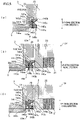
- the heat conduction mechanism 104 of the present embodiment is different from the heat conduction mechanism 4 of the first embodiment predominantly in regard to the positional relationship between a fixing member 141 and a separated member 142. While the separated member 42 is provided below the first inclined surfaces 41a of the fixing member 41 in the heat conduction mechanism 4 of the first embodiment, the separated member 142 is provided above first inclined surfaces 141a of the fixing member 141 in the heat conduction mechanism 104 of the present embodiment.
- Each first inclined surface 141a of the fixing member 141 is inclined so that the lower end is close to the outer circumferential surface of the spinning pack 2 as compared to the upper end.
- the lower surface of the fixing member 141 is covered by a heat insulation member 146a such as ceramic felt.
- each first screw hole 141b and each second screw hole 141c are formed along the up-down direction of the fixing member 141, and penetrate the fixing member 141.
- Each screw hole 141b and each second screw hole 141c are formed on the corresponding first inclined surface 141a.
- the four first screw holes 141b and the four second screw holes 141c are provided to correspond to four transferring blocks 143 which form the later-described separated member 142.
- Each first screw hole 141b is provided to be close to the heated box 3 as compared to the corresponding second screw hole 141c, at a gap between the heated box 3 and the spinning pack 2 which is inserted into the concave portion 32.
- a bolt 145a is moved upward and fitted to each first screw hole 141b.
- a bolt 145b is moved upward and fitted to each second screw hole 141c.
- a pushing member 145c is attached to a leading end portion of the bolt 145b for pushing the corresponding transferring block 143 upward, as described later.
- the upper end surface of the pushing member 145c is an inclined surface the inclination angle of which is the same as that of a later-described third inclined surface 143c of the transferring block 143.
- the upper end surface of the pushing member 145c may be a flat surface.
- the separated member 142 is formed of the four transferring blocks 143 which are provided along the circumferential direction of the spinning pack 2 inserted into the concave portion 32.
- Each transferring block 143 includes a second inclined surface 143a the inclination angle of which is the same as that of the corresponding first inclined surface 141a of the fixing member 141.
- the transferring block 143 is movable in the up-down direction while the second inclined surface 143a is in contact with the first inclined surface 141a of the fixing member 141.
- a concave portion 143d which is open downward is formed.
- Each transferring block 143 includes a contact surface 143b which can make contact with the outer circumferential surface of the spinning pack 2 inserted into the concave portion 32.
- the transferring block 143 includes the third inclined surface 143c which is inclined so that the upper end is close to the outer circumferential surface of the spinning pack 2 as compared to the lower end.
- the third inclined surface 143c faces obliquely downward and connects the second inclined surface 143a with the contact surface 143b.
- Each third inclined surface 143c is covered by a heat insulation member 146b such as ceramic felt.
- the bolt 145b is tightened as shown in FIG. 5(c) in order to detach the spinning pack 2 from the concave portion 32. Because of this, the upper end surface of the pushing member 145c attached to the bolt 145b makes contact with the third inclined surface 143c of the transferring block 143. As a result, the transferring block 143 is pushed upward. Subsequently, the contact surface 143b of the transferring block 143 is separated from the outer circumferential surface of the spinning pack 2 inserted into the concave portion 32. After that, the bolt 145a is tightened as shown in FIG. 5(a) so that the leading end of the bolt 145a is positioned in the concave portion 143d of the transferring block 143. Finally, the spinning pack 2 is detached from the concave portion 32.
- each first inclined surface 141a is inclined so that the lower end is close to the outer circumferential surface of the spinning pack 2 as compared to the upper end.
- the separated member 142 i.e., transferring blocks 143 is provided above the first inclined surfaces 141a. With this arrangement, as the separated member 142 (i.e., transferring blocks 143) moves downward because of its own weight, the separated member 142 (i.e., transferring blocks 143) reliably makes contact with the outer circumferential surface of the spinning pack 2.
- melt spinning device 201 of a third embodiment of the present invention will describe a melt spinning device 201 of a third embodiment of the present invention with reference to FIG. 6 .
- the structure of the melt spinning device 201 of the present embodiment is substantially identical with that of the melt spinning device 1 of the first embodiment, except a heat conduction mechanism 204.
- members identical with those in the first embodiment will be denoted by the same reference numerals as in the first embodiment, and the explanations thereof may not be repeated.
- the main difference between the heat conduction mechanism 204 of the present embodiment and the heat conduction mechanism 4 of the first embodiment is a structure by which transferring blocks 243 (i.e., separated member 242) are pushed upward. While the transferring blocks 43 (i.e., separated member 42) are moved upward as that the bolts 45 are tightened in the heat conduction mechanism 4 of the first embodiment, the transferring blocks 243 (i.e., separated member 242) are pushed and moved upward by a fitted member 248 in the heat conduction mechanism 204 of the present embodiment.
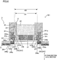
- the heat conduction mechanism 204 includes (i) a fixing member 241 having the lower surface which is covered by a heat insulation member 246a and (ii) the separated member 242 which is separated into the four transferring blocks 243 and has the lower surface which is covered by heat insulation members 246b, in the same manner as the heat conduction mechanism 4 of the first embodiment.
- the heat conduction mechanism 204 further includes a spring 247 which is attached to the lower surface of each transferring block 243, and a disc-shaped fitted member 248 which is fitted to the lower end portion of the concave portion 32.
- each transferring block 243 is moved upward while a second inclined surface 243a of the transferring block 243 is in contact with corresponding one of first inclined surfaces 241a of the fixing member 241.
- a contact surface 243b of the transferring block 243 makes contact with the outer circumferential surface of the spinning pack 2.
- a male screw 248a is formed on the outer circumferential surface of the fitted member 248.
- a female screw 232b is formed at the lower end portion of the wall surface defining the concave portion 32.
- the fitted member 248 is fitted to the lower end portion of the concave portion 32 in such a way that the male screw 248a of the fitted member 248 is meshed with the female screw 232b of the wall surface defining the concave portion 32.
- an opening 248b is formed to expose the spinneret 21 to the outside.
- a diameter D2 of the opening 248b is larger than a diameter D1 of the spinning pack 2.
- the fitted member 248 is made of a material having high heat conductivity, such as aluminum alloy, copper alloy, common steel, alloy steel, special steel, carbon fiber composite, and silicone rubber.
- the lower surface of the fitted member 248 is covered by a heat insulation member 246c such as ceramic felt.
- the following effects are obtained in addition to the effects obtained based on the structure identical with that in the first embodiment.
- the melt spinning device 201 of the present embodiment when the fitted member 248 is fitted to the lower end portion of the concave portion 32, the upward biasing force is applied to the transferring blocks 243 via the springs 247. Because of this, the transferring blocks 243 (i.e., separated member 242) are reliably in contact with the outer circumferential surface of the spinning pack 2.
- melt spinning device 301 of a fourth embodiment of the present invention will describe a melt spinning device 301 of a fourth embodiment of the present invention with reference to FIG. 7 .
- the structure of the melt spinning device 301 of the present embodiment is substantially identical with that of the melt spinning device 1 of the first embodiment, except a heat conduction mechanism 304.
- members identical with those in the first embodiment will be denoted by the same reference numerals as in the first embodiment, and the explanations thereof may not be repeated.
- the main difference between the heat conduction mechanism 304 of the present embodiment and the heat conduction mechanism 4 of the first embodiment is a structure by which transferring blocks 343 (i.e., separated member 342) are moved.
- transferring blocks 343 i.e., separated member 342
- the transferring blocks 343 are supported by springs 341 which are compression coil springs configured to elongate and contract in the direction toward and away from the spinning pack 2.
- the springs 341 are provided to correspond to the transferring blocks 343 of a separated member 342.
- the materials of the springs 341 and the separated member 342 are preferably high in heat conductivity. Examples of these materials include aluminum alloy, copper alloy, common steel, alloy steel, special steel, carbon fiber composite, and silicone rubber.
- the materials of the springs 341 and the separated member 342 may be any materials as long as the heat conductivities in these materials are higher at least than the heat conductivity in the static air layer.
- each spring 341 is attached to a surface of the corresponding transferring block 343. This surface of the transferring block 343 opposes the heated box 3.
- the spring 341 is detachably attached to the heated box 3 so that the other end portion, which is opposite to the one end portion attached to the transferring block 343, is in contact with the wall surface defining the concave portion 32 in the heated box 3.
- the spring 341 is provided in a recess 332a formed at the lower end portion of the wall surface defining the concave portion 32 of the heated box 3.
- a contact surface 343b of each transferring block 343 is provided outside the recess 332a.
- the length of the heat conduction mechanism 304 is longer than the size of a gap G (see FIG. 7(b) ) between the wall surface defining the concave portion 32 in the recess 332a and the outer circumferential surface of the spinning pack 2.
- a wall surface defining the recess 332a is formed of (i) a bottom surface which opposes the outer circumferential surface of the spinning pack 2 inserted into the concave portion 32 and (ii) side surfaces which are provided at the respective ends of the bottom surface in the up-down direction.
- the upper and lower surfaces of the transferring block 343 are in contact with both side surfaces of the recess 332a.
- the length of the transferring block 343 in the up-down direction is substantially equal to the length of the recess 332a in the up-down direction.
- Each transferring block 343 has an inclined surface 343a.
- the inclined surface 343a is formed on the lower surface of the transferring block 343 so that the inclined surface 343a and the spring 341 are formed on the opposite sides of the transferring block 343 in the gap-depth direction (i.e., left-right direction for a viewer of FIGs. 7(a) and 7(b) ).
- the inclined surface 343a is inclined with respect to the gap-depth direction so that the lower end is positioned to be close to the heated box 3 as compared to the upper end.
- the inclined surface 343a is covered by a heat insulation member 346b.
- the contact surface 343b of the transferring block 343 is in contact with the outer circumferential surface of the spinning pack 2.
- the contact surface 343b of the transferring block 343 is in contact with the area which is a part of the outer circumferential surface of the spinning pack 2 inserted into the concave portion 32 and where the spinneret 21 is formed in the up-down direction.
- the spring 341 contracts in accordance with the size of the gap between the wall surface defining the concave portion 32 and the outer circumferential surface of the spinning pack 2.
- the spring 341 applies the biasing force to the corresponding transferring block 343, in a direction toward the outer circumferential surface of the spinning pack 2.
- the spring 341 and the transferring block 343 form the heat conduction path from the wall surface defining the concave portion 32 in the heated box 3 to the outer circumferential surface of the spinning pack 2. Because of this, heat from the heated box 3 is transferred to the transferring block 343 from both side surfaces of the recess 332a in contact with the upper and lower surfaces of the transferring block 343. In addition to that, heat from the heated box 3 is transferred to the transferring block 343 via the spring 341. The heat transferred to the transferring block 343 is finally transferred to the spinning pack 2 in contact with the transferring block 343.
- each spring 341 applies the biasing force to the corresponding transferring block 343 in a direction toward the outer circumferential surface of the spinning pack 2. Because of this, the separated member 342 (i.e., transferring blocks 343) is reliably in contact with the spinning pack 2.
- the separated member 42 (142, 242, 342) is separated into four members with respect to the circumferential direction of the spinning pack 2, the disclosure is not limited to this.
- the number of members into which the separated member 42 (142, 242, 342) is separated may be optionally set on condition that the number of the members is two or more.
- each contact surface 43b (143b, 243b, 343b) of the separated member 42 (142, 242, 342) entirely makes contact with the area A which is a part of the outer circumferential surface of the spinning pack 2 and where the spinneret 21 is formed in the axial direction of the spinning pack 2 (i.e., the up-down direction).
- the disclosure is not limited to this.
- a part of each contact surface 43b (143b, 243b, 343b) of the separated member 42 (142, 242, 342) may make contact with the area A, or the entire separated member 42 (142, 242, 342) may make contact with the outside of the area A.
- the fixing member 41 (141, 241) including the first inclined surfaces 41a (141a, 241a) is attached to the wall surface defining the concave portion 32 in the heated box 3, the disclosure is not limited to this.
- the first inclined surfaces 41a (141a, 241a) may be included in the heated box 3.
- the lower surface of the fixing member 41 (141, 241) is covered by the heat insulation member 46a (146a, 246a).
- the lower surfaces of the separated member 42 (142, 242, 342) are covered by the heat insulation members 46b (146b, 246b, 346b).
- both the heat insulation member 46a (146a, 246a) and the heat insulation members 46b (146b, 246b, 346b) may not be provided.
- only the heat insulation member 46a (146a, 246a) or the heat insulation members 46b (146b, 246b, 346b) may be provided.
- each transferring block 143 is pushed upward by the pushing member 145c attached to the corresponding bolt 145b.
- the pushing member 145c may not be provided and the transferring block 143 may be pushed upward by the leading end portion of the bolt 145b.
- the male screw 248a is formed on the outer circumferential surface of the fitted member 248, and the female screw 232b configured to be meshed with the male screw 248a is formed at the lower end portion of the wall surface defining the concave portion 32.
- the disclosure is not limited to this.
- a male screw may be formed on the outer circumferential surface of the spinning pack 2 and a female screw configured to be meshed with this male screw may be formed on the inner circumferential surface of the fitted member 248.
- each transferring block 343 While in the fourth embodiment above the upper and lower surfaces of each transferring block 343 are in contact with both side surfaces of the recess 332a, the disclosure is not limited to this.
- the length of each transferring block 343 in the up-down direction may be sufficiently shorter than the length of the recess 332a in the up-down direction, with the result that the upper and lower surfaces of the transferring block 343 may be separated from both side surfaces of the recess 332a.
- the lower surface of the transferring block 343 is preferably covered by a heat insulation member.
- each contact surface 43b (143b, 243b, 343b) of the four transferring blocks 43 (143, 243, 343) may not entirely make contact with the outer circumferential surface of the spinning pack 2. In other words, a part of the contact surface 43b (143b, 243b, 343b) may make contact with the outer circumferential surface of the spinning pack 2.
Landscapes
- Engineering & Computer Science (AREA)
- Mechanical Engineering (AREA)
- Textile Engineering (AREA)
- Spinning Methods And Devices For Manufacturing Artificial Fibers (AREA)
Abstract


Description
- The present invention relates to a melt spinning device for producing a yarn from polymer.
- Typically, a melt spinning device includes (i) a heated box which is heated so that the temperature of the box is equal to or higher than a melting point of polymer and (ii) a spinning pack which is detachably attached to the heated box. In the melt spinning device, molten polymer supplied to the spinning pack via a polymer path is spun out from a spinneret of the spinning pack. The polymer path is formed inside the heated box.
- For example, Patent Literature 1 (
Japanese Laid-Open Patent Publication No. 2012-102435 - Patent Literature 2 (
Japanese Laid-Open Utility Model Publication No. S60-86569 -
Patent Literature 2 discloses a ring-shaped heating block which is in contact with the outer circumferential surface of a spinneret of a spinning pack. The heating block and the spinning pack may not be entirely in contact with each other but be partially in contact with each other because of, i.e., (i) the accuracy in production of members and (ii) the difference of positions between the heating block and the spinning pack. As a result, heat is transferred to the spinning pack unevenly in the circumferential direction of the spinning pack. - An object of the present invention is to provide a melt spinning device which improves the efficiency in transferring heat from a heated box to a spinning pack, and which is able to suppress the heat transfer to the spinning pack in the circumferential direction of the spinning pack from becoming uneven.
- According to a first aspect of the invention, a melt spinning device includes: a cylindrical spinning pack including a spinneret; a heated box including a concave portion having an internal space into which the spinning pack is inserted, the concave portion being open downward; and a heat conduction mechanism including a separated member which is able to make contact with an outer circumferential surface of the spinning pack inserted into the concave portion, the separated member being separated into plural members with respect to a circumferential direction of the spinning pack, and the heat conduction mechanism further including one or more members which include at least the separated member, and the one or more members forming a heat conduction path from a wall surface defining the concave portion in the heated box to the outer circumferential surface of the spinning pack when the spinning pack is inserted into the concave portion.
- According to this aspect, heat from the heated box is transferred to the spinning pack through the heat conduction path formed by the members which are included in the heat conduction mechanism. Because of this, the efficiency in transferring the heat from the heated box to the spinning pack is improved as compared to cases where the heat from the heated box is transferred to the spinning pack via an air layer. Because the separated member is separated into the plural members with respect to the circumferential direction of the spinning pack, the spinning pack and the separated member are unlikely to be partially in contact with each other. It is therefore possible to suppress the heat transfer to the spinning pack in the circumferential direction of the spinning pack from becoming uneven.
- According to a second aspect of the invention, the melt spinning device is arranged such that the separated member is configured to make contact with an area, the area being a part of the outer circumferential surface of the spinning pack inserted into the concave portion, and the spinneret being formed in the area in an axial direction of the spinning pack.
- According to this aspect, by the heat conduction mechanism, heat from the heated box is easily transferred to the part which is a part of the outer circumferential surface of the spinning pack and where the spinneret is provided. This suppresses the decrease in quality of yarns due to the low temperature of the spinneret.
- According to a third aspect of the invention, the melt spinning device is arranged such that the heat conduction mechanism further includes a first inclined surface provided to oppose the spinning pack over the separated member, the first inclined surface being inclined so that one end of the first inclined surface in an up-down direction is close to the outer circumferential surface of the spinning pack as compared to the other end of the first inclined surface in the up-down direction, and the separated member includes a second inclined surface an inclination angle of which is identical with an inclination angle of the first inclined surface, the separated member being movable in the up-down direction while the second inclined surface is in contact with the first inclined surface.
- According to this aspect, as the separated member moves in the up-down direction while the second inclined surface of the separated member is in contact with the first inclined surface, the separated member moves toward and away from the outer circumferential surface of the spinning pack. It is therefore possible to cause the separated member to make contact with the outer circumferential surface of the spinning pack, regardless of the size of a gap between the heated box and the spinning pack.
- According to a fourth aspect of the invention, the melt spinning device is arranged such that the first inclined surface is inclined so that an upper end of the first inclined surface is close to the outer circumferential surface of the spinning pack as compared to a lower end of the first inclined surface, and the separated member is provided below the first inclined surface.
- According to this aspect, because the separated member is provided below the first inclined surface, the heat conduction mechanism is easily assembled.
- According to a fifth aspect of the invention, the melt spinning device is arranged such that the separated member is fixed to the first inclined surface by a bolt.
- According to this aspect, because the separated member is fixed to the first inclined surface by tightening the bolt, a contact pressure between the separated member and the spinning pack is increased. It is therefore possible to further improve the efficiency in transferring heat from the heated box to the spinning pack.
- According to a sixth aspect of the invention, the melt spinning device is arranged such that the heat conduction mechanism further includes a biasing member which applies an upward biasing force to the separated member.
- According to this aspect, because the biasing member applies the upward biasing force to the separated member, the separated member is reliably in contact with the outer circumferential surface of the spinning pack.
- According to a seventh aspect of the invention, the melt spinning device is arranged such that the first inclined surface is inclined so that a lower end of the first inclined surface is close to the outer circumferential surface of the spinning pack as compared to an upper end of the first inclined surface, and the separated member is provided above the first inclined surface.
- According to this aspect, because the separated member is provided above the first inclined surface, the separated member moves downward because of its own weight. Because of this, the separated member is reliably in contact with the outer circumferential surface of the spinning pack.
- According to an eighth aspect of the invention, the melt spinning device is arranged such that the heat conduction mechanism further includes: a fixing member which is attached to the wall surface defining the concave portion in the heated box, the fixing member including the first inclined surface; and a first heat insulation member which covers a lower surface of the fixing member.
- According to this aspect, the first heat insulation member suppresses the heat radiation from the lower surface, which is exposed to the outside air, of the fixing member. It is therefore possible to further improve the efficiency in transferring heat from the heated box to the spinning pack.
- According to a ninth aspect of the invention, the melt spinning device is arranged such that the heat conduction mechanism further includes a second heat insulation member which covers an lower surface of the separated member.
- According to this aspect, the second heat insulation member suppresses the heat radiation from the lower surface, which is exposed to the outside air, of the separated member. It is therefore possible to further improve the efficiency in transferring heat from the heated box to the spinning pack.
-
-
FIG. 1 is a cross section of a melt spinning device related to a first embodiment of the present invention. -
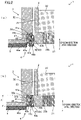
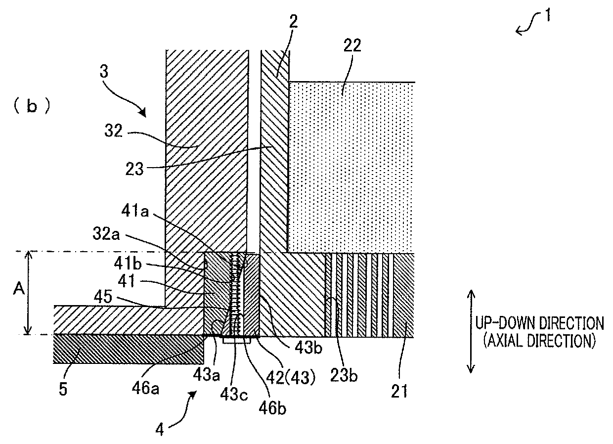
FIG. 2(a) is an enlarged view of a lower end portion and its surroundings of a concave portion in a heated box of the melt spinning device ofFIG. 1 in a state in which a bolt is loosened, andFIG. 2(b) is an enlarged view of the lower end portion and its surroundings in a state in which the bolt is tightened. -
FIG. 3 is an enlarged perspective view of a part of the melt spinning device viewed from below inFIG. 1 , and shows a separated member which is separated. -
FIG. 4 is a graph showing (i) the changes in temperature of a spinneret in the melt spinning device of the first embodiment and (ii) the changes in temperature of a spinneret in a melt spinning device of a comparative example. -
FIG. 5(a) is a cross section of a lower end portion and its surroundings of a concave portion in a heated box of a melt spinning device related to a second embodiment of the present invention in a state in which a spinning pack is not inserted into the concave portion,FIG. 5(b) is an cross section of the lower end portion and its surroundings in a state in which the spinning pack is inserted into the concave portion, andFIG. 5(c) is an cross section of the lower end portion and its surroundings in a state in which the spinning pack is being detached from the concave portion. -
FIG. 6 is a cross section of a lower end portion and its surroundings of a concave portion in a heated box of a melt spinning device related to a third embodiment of the present invention. -
FIG. 7 is a cross section of a lower end portion and its surroundings of a concave portion in a heated box of a melt spinning device related to a fourth embodiment of the present invention. - To begin with, the following will describe the overall structure of a
melt spinning device 1 of a first embodiment of the present invention with reference toFIG. 1 . Themelt spinning device 1 includes acylindrical spinning pack 2 having a spinneret 21, a heatedbox 3 havingconcave portions 32 which are open downward, aheat conduction mechanism 4, and acooling box 6. - In each
concave portion 32 of the heatedbox 3, apack attaching portion 31 to which thespinning pack 2 is detachably attached is provided. Thespinning pack 2, which is configured to be attached to thepack attaching portion 31, is inserted into the internal space of theconcave portion 32 so that the axial direction of thespinning pack 2 is in an up-down direction ofFIG. 1 . Eachconcave portion 32 has a circular shape in plan view. Theconcave portions 32 are staggered along the direction orthogonal to the plane ofFIG. 1 . At a lower end portion of a wall surface defining eachconcave portion 32, arecess 32a is provided. In the present specification, a part of the wall surface defining theconcave portion 32 is defined as a wall surface defining therecess 32a. A part of theheat conduction mechanism 4 is provided in thisrecess 32a. There is a gap which is approximately 1mm in width between (i) a part of the wall surface defining theconcave portion 32 except a part where therecess 32a is formed and (ii) the outer circumferential surface of thespinning pack 2 inserted into theconcave portion 32. - In the
heated box 3,polymer paths 33 are provided. Eachpolymer path 33 reaches thespinning pack 2, which is attached to the correspondingpack attaching portion 31 provided in theconcave portion 32, from an unillustrated spin pump. Thepack attaching portion 31 is fixed to the bottom surface of theconcave portion 32 by an unillustrated screw. Thepack attaching portion 31 includes a connectingportion 31a which protrudes downward and has an outer circumferential surface on which a male screw is formed. In thepack attaching portion 31, a throughhole 31b is formed as an end of thepolymer path 33. - In an
internal space 3a of theheated box 3, heat medium vapor supplied from an unillustrated heat medium boiler is sealed. The outer side surfaces of theheated box 3 are covered by aheat insulation member 5 such as ceramic felt. - The
spinning pack 2 includes apack member 23 in which there is aninternal space 2a. When thespinning pack 2 is attached to thepack attaching portion 31, theinternal space 2a is connected with thepolymer path 33. In theinternal space 2a of thepack member 23, a filtratingmember 22 is provided. In thepack member 23, a threaded-connection portion 23a having the top surface which is concave is formed. On the inner circumferential surface of the threaded-connection portion 23a, a female screw corresponding to the male screw of the connectingportion 31a of thepack attaching portion 31 is formed so that the threaded-connection portion 23a can be fitted to the connectingportion 31a. At the lower end of thepack member 23, anopening 23b which is open in the up-down direction is formed to allow theinternal space 2a to be communicated with the external space. To thisopening 23b, thespinneret 21 is fitted. - The
cooling box 6 is provided below theheated box 3. On the top surface of thecooling box 6, apacking 7 is provided. Thecooling box 6 is movable in the up-down direction by means of an unillustrated driving mechanism, and switchable between a state in which thecooling box 6 is in contact with the lower surface of theheated box 3 via the packing 7 (this state is shown inFIG. 1 ) and a state in which thecooling box 6 is separated from the lower surface of theheated box 3. - An
opening 71 is formed at a part of thepacking 7, which opposes theconcave portion 32 of theheated box 3. A part of the upper wall of thecooling box 6 and a part of the lower wall of thecooling box 6 oppose theconcave portion 32 of theheated box 3, andopenings cooling box 6. The space at a part which opposes theconcave portion 32 of theheated box 3 in thecooling box 6 is ayarn running space 6a through which molten polymer spun out from thespinneret 21 passes. The space in thecooling box 6 is partitioned into theyarn running space 6a and other space by afilter 63. To thecooling box 6, cooling air is supplied through an unillustrated duct. The cooling air supplied to thecooling box 6 is sent to theyarn running space 6a through thefilter 63. - In the
melt spinning device 1 configured as described above, the heat medium vapor is supplied to theinternal space 3a of theheated box 3 from the heat medium boiler (not illustrated). The heat medium vapor supplied to theinternal space 3a of theheated box 3 heats theheated box 3 so that the temperature of the box is increased to a predetermined spinning temperature which is equal to or higher than the melting point of polymer. After that, each spinningpack 2 is inserted to the correspondingconcave portion 32 in theheated box 3 and attached to thepack attaching portion 31. In this regard, each spinningpack 2 is heated by a heating unit (not illustrated) so that the temperature of thespinning pack 2 is substantially identical with the spinning temperature. To thespinning pack 2 attached to thepack attaching portion 31, heat from theheated box 3 is transferred by theheat conduction mechanism 4. - High-temperature molten polymer, such as nylon and polyester, which is supplied from the spin pump (not illustrated) is sent to the
internal space 2a of thespinning pack 2 through thepolymer path 33. The molten polymer sent to theinternal space 2a of thespinning pack 2 is filtered by the filtratingmember 22, and then spun out from thespinneret 21. The molten polymer spun out from thespinneret 21 passes through theyarn running space 6a in thecooling box 6. At this time, the molten polymer passing theyarn running space 6a is cooled by the cooling air supplied to theyarn running space 6a. - The following will describe the
heat conduction mechanism 4 with reference toFIGs. 2(a) and 2(b) andFIG. 3 . Theheat conduction mechanism 4 is provided at the gap between (i) the wall surface defining theconcave portion 32 formed in theheated box 3 and (ii) thespinning pack 2 inserted into theconcave portion 32. The main components of theheat conduction mechanism 4 are a fixingmember 41, a separatedmember 42 formed of four transferringblocks 43, andheat insulation members member 41 and the separatedmember 42 are preferably high in heat conductivity. Examples of these materials include aluminum alloy, copper alloy, common steel, alloy steel, special steel, carbon fiber composite, and silicone rubber. The materials of the fixingmember 41 and the separatedmember 42 may be any materials as long as the heat conductivities in these materials are higher at least than the heat conductivity in the static air layer. - The fixing
member 41 is in contact with the wall surface defining theconcave portion 32 in theheated box 3. The fixingmember 41 is attached to the wall surface defining theconcave portion 32 in theheated box 3 by bolts (not illustrated). The fixingmember 41 is provided to oppose thespinning pack 2 over the separatedmember 42. The fixingmember 41 is provided in therecess 32a formed at the lower end portion of the wall surface defining theconcave portion 32 of theheated box 3. The fixingmember 41 is provided to surround the circumference of thespinning pack 2 which is inserted into theconcave portion 32. - As shown in
FIGs. 2(a) and 2(b) , the fixingmember 41 includes four firstinclined surfaces 41a each of which is inclined so that the upper end is close to the outer circumferential surface of thespinning pack 2 as compared to the lower end. Each firstinclined surface 41a faces thespinning pack 2 at the gap between the wall surface defining theconcave portion 32 formed in theheated box 3 and the outer circumferential surface of thespinning pack 2 inserted into theconcave portion 32. As shown inFIG. 3 , the four firstinclined surfaces 41a are flat surfaces provided to surround the circumference of thespinning pack 2 which is inserted into theconcave portion 32. - In the fixing
member 41, fourscrew holes 41b are formed to correspond tolong holes 43c (described later) which are respectively formed in the four transferringblocks 43 forming the separatedmember 42. Eachscrew hole 41b is formed along the up-down direction of the fixingmember 41, and penetrates the fixingmember 41. The lower end of eachscrew hole 41b is formed on the corresponding firstinclined surface 41a. The lower surface of the fixingmember 41 is covered by aheat insulation member 46a such as ceramic felt. - The separated
member 42 is provided between the fixingmember 41 and thespinning pack 2 and below the firstinclined surfaces 41a of the fixingmember 41. As shown inFIG. 3 , the separatedmember 42 is formed of the four transferringblocks 43 which are provided along the circumferential direction of thespinning pack 2 inserted into theconcave portion 32. In other words, the separatedmember 42 is separated into four members with respect to the circumferential direction of thespinning pack 2 which is inserted into theconcave portion 32. The lower surface of each transferringblock 43 is covered by aheat insulation member 46b such as ceramic felt. - Each transferring
block 43 includes a secondinclined surface 43a corresponding to one of the four firstinclined surfaces 41a of the fixingmember 41. The inclination angle of the secondinclined surface 43a is the same as that of the corresponding firstinclined surface 41a. The secondinclined surface 43a faces the wall surface defining theconcave portion 32 at the gap between the wall surface defining theconcave portion 32 formed in theheated box 3 and the outer circumferential surface of thespinning pack 2 inserted into theconcave portion 32. - Each transferring
block 43 includes acontact surface 43b which can make contact with the outer circumferential surface of thespinning pack 2 inserted into theconcave portion 32. The curvature of thecontact surface 43b is substantially identical with that of the outer circumferential surface of thespinning pack 2. Thecontact surface 43b faces thespinning pack 2 at the gap between the wall surface defining theconcave portion 32 formed in theheated box 3 and the outer circumferential surface of thespinning pack 2 which is inserted into theconcave portion 32. - As shown in
FIGs. 2(a) and 2(b) , eachlong hole 43c is formed to penetrate the corresponding transferringblock 43 in the up-down direction of the transferringblock 43. Thelong hole 43c is formed on the corresponding secondinclined surface 43a. As shown inFIG. 3 , thelong hole 43c has an ellipse shape which is long in the direction orthogonal to the outer circumferential surface of thespinning pack 2. Each transferringblock 43 is fixed to the fixingmember 41 in such a way that the leading end of abolt 45, which is inserted upward into thelong hole 43c, is screwed with thecorresponding screw hole 41b formed in the fixingmember 41. - When the
bolt 45 is loosened as shown inFIG. 2(a) , the transferringblock 43 is movable in the up-down direction while the secondinclined surface 43a is in contact with the firstinclined surface 41a of the fixingmember 41. The transferringblock 43 moves upward while the secondinclined surface 43a is in contact with the firstinclined surface 41a, so as to move toward the spinning pack 2 (i.e., move away from the heated box 3). In addition to that, (i) as the transferringblock 43 moves downward while the secondinclined surface 43a is in contact with the firstinclined surface 41a or (ii) as the transferringblock 43 moves downward so that the secondinclined surface 43a is separated from the firstinclined surface 41a, the transferringblock 43 moves away from the spinning pack 2 (i.e., moves toward the heated box 3). - As the
bolt 45 is tightened as shown inFIG. 2(b) , the transferringblock 43 moves upward so that thecontact surface 43b of the transferringblock 43 makes contact with the outer circumferential surface of thespinning pack 2 which is inserted into theconcave portion 32. When at least one transferringblock 43 is in contact with the outer circumferential surface of thespinning pack 2 as shown inFIG. 2(b) , thecontact surface 43b of this transferringblock 43 is in contact with the outer circumferential surface of thespinning pack 2 in the circumferential direction of thespinning pack 2. In other words, when four transferringblocks 43 are in contact with the outer circumferential surface of thespinning pack 2, the separated member 42 (i.e., four transferring blocks 43) is in contact with the outer circumferential surface of thespinning pack 2 in the circumferential surface of thespinning pack 2. When the four transferringblocks 43 are in contact with the outer circumferential surface of thespinning pack 2, there is hardly a gap between the adjacent transferring blocks 43. Therefore, in this case, the separated member 42 (i.e., four transferring blocks 43) is formed almost across the entire circumference of thespinning pack 2 in the circumferential direction of thespinning pack 2. Thecontact surface 43b of the transferringblock 43 is in contact with an area A (seeFIG. 2(b) ) which is a part of the outer circumferential surface of thespinning pack 2 inserted into theconcave portion 32 and where thespinneret 21 is formed in the axial direction of the spinning pack 2 (i.e., up-down direction). In the present embodiment, theentire contact surface 43b is provided in the area A. - When the
contact surface 43b of the transferringblock 43 is in contact with the outer circumferential surface of thespinning pack 2, the fixingmember 41 and the transferringblock 43 form a heat conduction path from the wall surface defining theconcave portion 32 in theheated box 3 to the outer circumferential surface of thespinning pack 2. With this arrangement, to begin with, heat from theheated box 3 is transferred to the fixingmember 41 in contact with theheated box 3. The heat transferred to the fixingmember 41 is then transferred to each transferringblock 43 in contact with the fixingmember 41. The heat transferred to the transferringblock 43 is finally transferred to thespinning pack 2 in contact with the transferringblock 43. - In order to attach/detach the
spinning pack 2 to/from thepack attaching portion 31, eachbolt 45 is loosened so that the corresponding transferringblock 43 is movable. At this time, the transferringblock 43 moves downward due to the gravity. That is, the transferringblock 43 moves toward the heated box 3 (i.e., moves away from thespinning pack 2 which is inserted into the concave portion 32). With this, thespinning pack 2 can be attached to or detached from the pack attaching portion 31 (seeFIG. 2(a) ). After thespinning pack 2 is attached to thepack attaching portion 31, eachbolt 45 is tightened so that thecontact surface 43b of the corresponding transferringblock 43 makes contact with the outer circumferential surface of the spinning pack 2 (seeFIG. 2(b) ). - In the
melt spinning device 1, cleaning of surfaces is required for regularly removing contaminants adhered to the surface of thespinneret 21. When molten polymer is spun out from thespinneret 21 during the cleaning of surfaces, the molten polymer is discarded. Therefore, in order not to wastefully consume molten polymer, the cleaning of surfaces may be performed while molten polymer is not spun out from thespinneret 21. During the cleaning of surfaces, thecooling box 6 is moved downward so that thecooling box 6 is switched from the state in which thecooling box 6 is in contact with the lower surface of theheated box 3 via thepacking 7 to the state in which thecooling box 6 is separated from the lower surface of theheated box 3. After the cleaning of surfaces, thecooling box 6 is moved upward so that thecooling box 6 is switched from the state in which thecooling box 6 is separated from the lower surface of theheated box 3 to the state in which thecooling box 6 is in contact with the lower surface of theheated box 3 via thepacking 7. Before being attached to theheated box 3, thespinning pack 2 is preliminary heated so that the temperature of thespinning pack 2 is increased to be a predetermined temperature. However, thespinneret 21 is exposed to the outside air until thecooling box 6 makes contact with the lower surface of theheated box 3. As a result, the temperature of thespinneret 21 is decreased. When the temperature of thespinneret 21 is decreased, the quality of spun-out yarns is deteriorated after the cleaning of the surfaces is performed and the spinning of the molten polymer from thespinneret 21 is resumed. It is therefore required to increase the temperature of thespinneret 21 as soon as the cleaning of surfaces finishes. - The graph of
FIG. 4 shows (i) the changes in temperature of aspinneret 21 in a melt spinning device of an example and (ii) the changes in temperature of aspinneret 21 in a melt spinning device of a comparative example. To be more specific, the graph ofFIG. 4 shows the change in temperature of eachspinneret 21 since the attachment of the spinning packs 2 to theheated boxes 3. - The example uses the
melt spinning device 1 of the first embodiment described above, and common steel is used as the materials of the fixingmember 41 and the separatedmember 42. The melt spinning device of the comparative example does not include theheat conduction mechanism 4, and therecess 32a is not formed in theconcave portion 32 of theheated box 3. Except these differences, the melt spinning device is the same as that of themelt spinning device 1 of the embodiment described above. In the melt spinning device of the comparative example, there is a gap which is approximately 1.0 mm in width between the wall surface defining theconcave portion 32 and the outer circumferential surface of thespinning pack 2 which is inserted into theconcave portion 32. In the melt spinning device of the comparative example, heat from theheated box 3 is transferred to thespinning pack 2 via the air layer at this gap which is approximately 1.0 mm in width. - In the graph of
FIG. 4 , the vertical axis indicates the temperature (°C) of eachspinneret 21 and the horizontal axis indicates the elapsed time (minutes) since the attachment of the spinning packs 2 to theheated boxes 3 in both examples. In addition to that, the bold solid line indicates the temperature measured at the central portion of the lower surface of thespinneret 21 of the example, and the bold dashed line indicates the temperature measured at the central portion of the lower surface of thespinneret 21 of the comparative example. In addition to that, a thin solid line indicates the average of temperatures measured at a side surface of thespinneret 21 of the example, and a thin dashed line indicates the average of temperatures measured at a side surface of thespinneret 21 of the comparative example. - As shown in
FIG. 4 , after the spinning packs 2 are attached to theheated boxes 3, decrease in temperature at the central portion of the lower surface of thespinneret 21 of the example is gradual as compared to decrease in temperature at the central portion of thespinneret 21 of the comparative example. After thecooling boxes 6 are moved to make contact with the lower surfaces of theheated boxes 3 via thepackings 7 in both examples after approximately three minutes elapse since the start of measuring the temperatures, the temperature at the central portion of the lower surface of thespinneret 21 of the example swiftly increases. Meanwhile, the temperature at the central portion of the lower surface of thespinneret 21 of the comparative example takes time to start increasing and slowly increases as compared to the example. In regard to the averages of the temperatures at the side surfaces of thespinnerets 21, after the spinning packs 2 are attached to theheated boxes 3 in both examples, the temperature of thespinneret 21 of the example scarcely changes and decreases as compared to a case where the temperature of thespinneret 21 of the comparative example changes and decreases. - As described above, the
melt spinning device 1 of the present embodiment includes thecylindrical spinning pack 2 having thespinneret 21, theheated box 3 having theconcave portion 32 into the internal space of which thespinning pack 2 is inserted and which is open downward, and theheat conduction mechanism 4 having the separatedmember 42 which can make contact with the outer circumferential surface of thespinning pack 2 inserted into theconcave portion 32 and which is separated into the four transferringblocks 43 with respect to the circumferential direction of thespinning pack 2. When thespinning pack 2 is inserted into theconcave portion 32, one or more members which include the separatedmember 42 and which are included in theheat conduction mechanism 4 form the heat conduction path from the wall surface defining theconcave portion 32 in theheated box 3 to the outer circumferential surface of thespinning pack 2. - With this arrangement, heat from the
heated box 3 is transferred to thespinning pack 2 through the heat conduction path formed by the members which include at least the separatedmember 42 and which are included in theheat conduction mechanism 4. Because of this, the efficiency in transferring the heat from theheated box 3 to thespinning pack 2 is improved as compared to cases where the heat from theheated box 3 is transferred to thespinning pack 2 via the air layer. Because the separatedmember 42 is separated into plural members with respect to the circumferential direction of thespinning pack 2, thespinning pack 2 and the separatedmember 42 are unlikely to be partially in contact with each other. It is therefore possible to suppress the heat transfer to thespinning pack 2 in the circumferential direction of thespinning pack 2 from becoming uneven. - In the
melt spinning device 1 of the present embodiment, the separated member 42 (i.e., transferring blocks 43) is in contact with an area A which is a part of the outer circumferential surface of thespinning pack 2 inserted into theconcave portion 32 and where thespinneret 21 is formed in the axial direction of the spinning pack 2 (i.e., up-down direction). Therefore, by theheat conduction mechanism 4, heat from theheated box 3 is easily transferred to the part which is a part of the outer circumferential surface of thespinning pack 2 and where thespinneret 21 is provided. This suppresses the decrease in quality of the yarns due to the low temperature of thespinneret 21. - In the
melt spinning device 1 of the present embodiment, theheat conduction mechanism 4 further includes the firstinclined surfaces 41a which oppose thespinning pack 2 over the separatedmember 42 and each of which is inclined so that the upper end is close to the outer circumferential surface of thespinning pack 2 as compared to the lower end. The separated member 42 (i.e., transferring blocks 43) includes the secondinclined surfaces 43a the inclination angles of which are identical with those of the firstinclined surfaces 41a, and is provided to be movable in the up-down direction while the secondinclined surfaces 43a are in contact with the firstinclined surfaces 41a. With this arrangement, as the separated member 42 (i.e., transferring blocks 43) moves in the up-down direction while the secondinclined surfaces 43a of the separated member 42 (i.e., transferring blocks 43) are in contact with the firstinclined surfaces 41a, the separated member 42 (i.e., transferring blocks 43) moves toward and away from the outer circumferential surface of thespinning pack 2. It is therefore possible to cause the separated member 42 (i.e., transferring blocks 43) to make contact with the outer circumferential surface of thespinning pack 2, regardless of the size of the gap between theheated box 3 and thespinning pack 2. - In the
melt spinning device 1 of the present embodiment, the separated member 42 (i.e., transferring blocks 43) is provided below the firstinclined surfaces 41a. Because the separated member 42 (i.e., transferring blocks 43) is provided below the firstinclined surfaces 41a, theheat conduction mechanism 4 is easily assembled. - In the
melt spinning device 1 of the present embodiment, theheat conduction mechanism 4 further includes the fixingmember 41 which is attached to the wall surface defining theconcave portion 32 in theheated box 3 and which includes the firstinclined surfaces 41a. In this regard, the separated member 42 (i.e., transferring blocks 43) is fixed to the fixing member 41 (i.e., the firstinclined surfaces 41a) by thebolts 45. With this arrangement, because the separated member 42 (i.e., transferring blocks 43) is fixed to the fixingmember 41 by tightening thebolts 45, the contact pressure between the separated member 42 (i.e., transferring blocks 43) and thespinning pack 2 is increased. It is therefore possible to further improve the efficiency in transferring heat from theheated box 3 to thespinning pack 2. - In the
melt spinning device 1 of the present embodiment, the lower surface of the fixingmember 41 is covered by theheat insulation member 46a. With this arrangement, theheat insulation member 46a suppresses the heat radiation from the lower surface, which is exposed to the outside air, of the fixingmember 41. It is therefore possible to further improve the efficiency in transferring heat from theheated box 3 to thespinning pack 2. - In the
melt spinning device 1 of the present embodiment, the lower surface of the separated member 42 (i.e., the lower surfaces of the transferring blocks 43) is covered by theheat insulation members 46b. With this arrangement, theheat insulation members 46b suppress the heat radiation from the lower surface, which is exposed to the outside air, of the separated member 42 (i.e., the lower surfaces of the transferring blocks 43). It is therefore possible to further improve the efficiency in transferring heat from theheated box 3 to thespinning pack 2. - The following will describe a
melt spinning device 101 of a second embodiment of the present invention with reference toFIG. 5 . The structure of themelt spinning device 101 of the present embodiment is the same as that of themelt spinning device 1 of the first embodiment, except aheat conduction mechanism 104. In the descriptions below, members identical with those in the first embodiment will be denoted by the same reference numerals as in the first embodiment, and the explanations thereof may not be repeated. - The
heat conduction mechanism 104 of the present embodiment is different from theheat conduction mechanism 4 of the first embodiment predominantly in regard to the positional relationship between a fixingmember 141 and a separatedmember 142. While the separatedmember 42 is provided below the firstinclined surfaces 41a of the fixingmember 41 in theheat conduction mechanism 4 of the first embodiment, the separatedmember 142 is provided above firstinclined surfaces 141a of the fixingmember 141 in theheat conduction mechanism 104 of the present embodiment. - Each first
inclined surface 141a of the fixingmember 141 is inclined so that the lower end is close to the outer circumferential surface of thespinning pack 2 as compared to the upper end. The lower surface of the fixingmember 141 is covered by aheat insulation member 146a such as ceramic felt. - In the fixing
member 141, four first screw holes 141b and four second screw holes 141c are formed. Eachfirst screw hole 141b and eachsecond screw hole 141c are formed along the up-down direction of the fixingmember 141, and penetrate the fixingmember 141. Eachscrew hole 141b and eachsecond screw hole 141c are formed on the corresponding firstinclined surface 141a. The four first screw holes 141b and the four second screw holes 141c are provided to correspond to four transferringblocks 143 which form the later-described separatedmember 142. Eachfirst screw hole 141b is provided to be close to theheated box 3 as compared to the correspondingsecond screw hole 141c, at a gap between theheated box 3 and thespinning pack 2 which is inserted into theconcave portion 32. - A
bolt 145a is moved upward and fitted to eachfirst screw hole 141b. Abolt 145b is moved upward and fitted to eachsecond screw hole 141c. To a leading end portion of thebolt 145b, a pushingmember 145c is attached for pushing the corresponding transferringblock 143 upward, as described later. In the present embodiment, the upper end surface of the pushingmember 145c is an inclined surface the inclination angle of which is the same as that of a later-described thirdinclined surface 143c of the transferringblock 143. Alternatively, the upper end surface of the pushingmember 145c may be a flat surface. - The separated
member 142 is formed of the four transferringblocks 143 which are provided along the circumferential direction of thespinning pack 2 inserted into theconcave portion 32. Each transferringblock 143 includes a secondinclined surface 143a the inclination angle of which is the same as that of the corresponding firstinclined surface 141a of the fixingmember 141. The transferringblock 143 is movable in the up-down direction while the secondinclined surface 143a is in contact with the firstinclined surface 141a of the fixingmember 141. In the secondinclined surface 143a, aconcave portion 143d which is open downward is formed. - Each transferring
block 143 includes acontact surface 143b which can make contact with the outer circumferential surface of thespinning pack 2 inserted into theconcave portion 32. In addition to that, the transferringblock 143 includes the thirdinclined surface 143c which is inclined so that the upper end is close to the outer circumferential surface of thespinning pack 2 as compared to the lower end. The thirdinclined surface 143c faces obliquely downward and connects the secondinclined surface 143a with thecontact surface 143b. Each thirdinclined surface 143c is covered by aheat insulation member 146b such as ceramic felt. - As shown in
FIG. 5(a) , when thespinning pack 2 is not inserted into theconcave portion 32, the leading end of thebolt 145a screwed with the correspondingfirst screw hole 141b is positioned in aconcave portion 143d formed in the transferringblock 143. Because of this, the transferringblock 143 is prevented from sliding on and falling along the firstinclined surface 141a of the fixingmember 141. - As shown in
FIG. 5(b) , when thebolt 145a is loosened after thespinning pack 2 is inserted into theconcave portion 32, the leading end of thebolt 145a is positioned in the correspondingfirst screw hole 141b. As a result, the transferringblock 143 moves downward because of its own weight. Because of this, thecontact surface 143b of the transferringblock 143 is in contact with the outer circumferential surface of thespinning pack 2 which is inserted into theconcave portion 32. At this time, the fixingmember 141 and the transferringblock 143 form a heat conduction path from the wall surface defining theconcave portion 32 in theheated box 3 to the outer circumferential surface of thespinning pack 2. - To begin with, the
bolt 145b is tightened as shown inFIG. 5(c) in order to detach thespinning pack 2 from theconcave portion 32. Because of this, the upper end surface of the pushingmember 145c attached to thebolt 145b makes contact with the thirdinclined surface 143c of the transferringblock 143. As a result, the transferringblock 143 is pushed upward. Subsequently, thecontact surface 143b of the transferringblock 143 is separated from the outer circumferential surface of thespinning pack 2 inserted into theconcave portion 32. After that, thebolt 145a is tightened as shown inFIG. 5(a) so that the leading end of thebolt 145a is positioned in theconcave portion 143d of the transferringblock 143. Finally, thespinning pack 2 is detached from theconcave portion 32. - In the present embodiment, the following effects are obtained in addition to the effects obtained based on the structure identical with that in the first embodiment. In the
melt spinning device 101 of the present embodiment, each firstinclined surface 141a is inclined so that the lower end is close to the outer circumferential surface of thespinning pack 2 as compared to the upper end. In addition to that, the separated member 142 (i.e., transferring blocks 143) is provided above the firstinclined surfaces 141a. With this arrangement, as the separated member 142 (i.e., transferring blocks 143) moves downward because of its own weight, the separated member 142 (i.e., transferring blocks 143) reliably makes contact with the outer circumferential surface of thespinning pack 2. - The following will describe a melt spinning device 201 of a third embodiment of the present invention with reference to
FIG. 6 . The structure of the melt spinning device 201 of the present embodiment is substantially identical with that of themelt spinning device 1 of the first embodiment, except aheat conduction mechanism 204. In the descriptions below, members identical with those in the first embodiment will be denoted by the same reference numerals as in the first embodiment, and the explanations thereof may not be repeated. - The main difference between the
heat conduction mechanism 204 of the present embodiment and theheat conduction mechanism 4 of the first embodiment is a structure by which transferring blocks 243 (i.e., separated member 242) are pushed upward. While the transferring blocks 43 (i.e., separated member 42) are moved upward as that thebolts 45 are tightened in theheat conduction mechanism 4 of the first embodiment, the transferring blocks 243 (i.e., separated member 242) are pushed and moved upward by a fittedmember 248 in theheat conduction mechanism 204 of the present embodiment. - The
heat conduction mechanism 204 includes (i) a fixingmember 241 having the lower surface which is covered by aheat insulation member 246a and (ii) the separatedmember 242 which is separated into the four transferringblocks 243 and has the lower surface which is covered byheat insulation members 246b, in the same manner as theheat conduction mechanism 4 of the first embodiment. Theheat conduction mechanism 204 further includes aspring 247 which is attached to the lower surface of each transferringblock 243, and a disc-shaped fittedmember 248 which is fitted to the lower end portion of theconcave portion 32. - When the fitted
member 248 is fitted to the lower end portion of theconcave portion 32, the transferring blocks 243 are pushed upward via thesprings 247 attached to the lower surfaces of the transferring blocks 243. In addition to that, each transferringblock 243 is moved upward while a secondinclined surface 243a of the transferringblock 243 is in contact with corresponding one of firstinclined surfaces 241a of the fixingmember 241. As a result, acontact surface 243b of the transferringblock 243 makes contact with the outer circumferential surface of thespinning pack 2. - A
male screw 248a is formed on the outer circumferential surface of the fittedmember 248. In addition to that, afemale screw 232b is formed at the lower end portion of the wall surface defining theconcave portion 32. The fittedmember 248 is fitted to the lower end portion of theconcave portion 32 in such a way that themale screw 248a of the fittedmember 248 is meshed with thefemale screw 232b of the wall surface defining theconcave portion 32. At the central portion of the fittedmember 248, anopening 248b is formed to expose thespinneret 21 to the outside. A diameter D2 of theopening 248b is larger than a diameter D1 of thespinning pack 2. Because of this, when the fittedmember 248 is loosened, the attachment and detachment of thespinning pack 2 can be performed without removing the fittedmember 248 from the lower end portion of theconcave portion 32. The fittedmember 248 is made of a material having high heat conductivity, such as aluminum alloy, copper alloy, common steel, alloy steel, special steel, carbon fiber composite, and silicone rubber. The lower surface of the fittedmember 248 is covered by aheat insulation member 246c such as ceramic felt. - In the present embodiment, the following effects are obtained in addition to the effects obtained based on the structure identical with that in the first embodiment. In the melt spinning device 201 of the present embodiment, when the fitted
member 248 is fitted to the lower end portion of theconcave portion 32, the upward biasing force is applied to the transferring blocks 243 via thesprings 247. Because of this, the transferring blocks 243 (i.e., separated member 242) are reliably in contact with the outer circumferential surface of thespinning pack 2. - The following will describe a
melt spinning device 301 of a fourth embodiment of the present invention with reference toFIG. 7 . The structure of themelt spinning device 301 of the present embodiment is substantially identical with that of themelt spinning device 1 of the first embodiment, except aheat conduction mechanism 304. In the descriptions below, members identical with those in the first embodiment will be denoted by the same reference numerals as in the first embodiment, and the explanations thereof may not be repeated. - The main difference between the
heat conduction mechanism 304 of the present embodiment and theheat conduction mechanism 4 of the first embodiment is a structure by which transferring blocks 343 (i.e., separated member 342) are moved. In theheat conduction mechanism 4 of the first embodiment, as each transferringblock 43 is moved in the up-down direction while the secondinclined surface 43a of the transferringblock 43 is in contact with the corresponding firstinclined surface 41a of the fixingmember 41, the transferringblock 43 is moved toward and away from thespinning pack 2. Meanwhile, in theheat conduction mechanism 304 of the present embodiment, the transferring blocks 343 (i.e., separated member 342) are supported bysprings 341 which are compression coil springs configured to elongate and contract in the direction toward and away from thespinning pack 2. - The
springs 341 are provided to correspond to the transferring blocks 343 of a separatedmember 342. The materials of thesprings 341 and the separatedmember 342 are preferably high in heat conductivity. Examples of these materials include aluminum alloy, copper alloy, common steel, alloy steel, special steel, carbon fiber composite, and silicone rubber. The materials of thesprings 341 and the separatedmember 342 may be any materials as long as the heat conductivities in these materials are higher at least than the heat conductivity in the static air layer. - One end portion of each
spring 341 is attached to a surface of thecorresponding transferring block 343. This surface of the transferringblock 343 opposes theheated box 3. Thespring 341 is detachably attached to theheated box 3 so that the other end portion, which is opposite to the one end portion attached to the transferringblock 343, is in contact with the wall surface defining theconcave portion 32 in theheated box 3. - The
spring 341 is provided in arecess 332a formed at the lower end portion of the wall surface defining theconcave portion 32 of theheated box 3. Acontact surface 343b of each transferringblock 343 is provided outside therecess 332a. In the gap-depth direction, when no external force is applied to the transferringblock 343, the length of theheat conduction mechanism 304 is longer than the size of a gap G (seeFIG. 7(b) ) between the wall surface defining theconcave portion 32 in therecess 332a and the outer circumferential surface of thespinning pack 2. A wall surface defining therecess 332a is formed of (i) a bottom surface which opposes the outer circumferential surface of thespinning pack 2 inserted into theconcave portion 32 and (ii) side surfaces which are provided at the respective ends of the bottom surface in the up-down direction. The upper and lower surfaces of the transferringblock 343 are in contact with both side surfaces of therecess 332a. In other words, the length of the transferringblock 343 in the up-down direction is substantially equal to the length of therecess 332a in the up-down direction. - Each transferring
block 343 has aninclined surface 343a. Theinclined surface 343a is formed on the lower surface of the transferringblock 343 so that theinclined surface 343a and thespring 341 are formed on the opposite sides of the transferringblock 343 in the gap-depth direction (i.e., left-right direction for a viewer ofFIGs. 7(a) and 7(b) ). Theinclined surface 343a is inclined with respect to the gap-depth direction so that the lower end is positioned to be close to theheated box 3 as compared to the upper end. Theinclined surface 343a is covered by aheat insulation member 346b. - As the
spinning pack 2 is inserted upward into theconcave portion 32 as shown inFIG. 7(a) , the upper end of thespinning pack 2 makes contact with theinclined surface 343a of the transferringblock 343. As thespinning pack 2 is further moved upward while the upper end of thespinning pack 2 is in contact with theinclined surface 343a of the transferringblock 343, the transferringblock 343 moves toward theheated box 3. As a result, thespring 341 contracts. - As shown in
FIG. 7(b) , when thespinning pack 2 is entirely inserted into theconcave portion 32, thecontact surface 343b of the transferringblock 343 is in contact with the outer circumferential surface of thespinning pack 2. To be more specific, thecontact surface 343b of the transferringblock 343 is in contact with the area which is a part of the outer circumferential surface of thespinning pack 2 inserted into theconcave portion 32 and where thespinneret 21 is formed in the up-down direction. Thespring 341 contracts in accordance with the size of the gap between the wall surface defining theconcave portion 32 and the outer circumferential surface of thespinning pack 2. Thespring 341 applies the biasing force to thecorresponding transferring block 343, in a direction toward the outer circumferential surface of thespinning pack 2. - When the
contact surface 343b of the transferringblock 343 is in contact with the outer circumferential surface of thespinning pack 2, thespring 341 and the transferringblock 343 form the heat conduction path from the wall surface defining theconcave portion 32 in theheated box 3 to the outer circumferential surface of thespinning pack 2. Because of this, heat from theheated box 3 is transferred to the transferringblock 343 from both side surfaces of therecess 332a in contact with the upper and lower surfaces of the transferringblock 343. In addition to that, heat from theheated box 3 is transferred to the transferringblock 343 via thespring 341. The heat transferred to the transferringblock 343 is finally transferred to thespinning pack 2 in contact with the transferringblock 343. - In the present embodiment, the following effects are obtained in addition to the effects obtained based on the structure identical with that in the first embodiment. In the
melt spinning device 301 of the present embodiment, eachspring 341 applies the biasing force to thecorresponding transferring block 343 in a direction toward the outer circumferential surface of thespinning pack 2. Because of this, the separated member 342 (i.e., transferring blocks 343) is reliably in contact with thespinning pack 2. - The embodiments of the present invention are described hereinabove. However, the specific structure of the present invention shall not be interpreted as to be limited to the above described embodiments. The scope of the present invention is defined not by the above embodiments but by claims set forth below, and shall encompass the equivalents in the meaning of the claims and every modification within the scope of the claims.
- While in the embodiments above the separated member 42 (142, 242, 342) is separated into four members with respect to the circumferential direction of the
spinning pack 2, the disclosure is not limited to this. The number of members into which the separated member 42 (142, 242, 342) is separated may be optionally set on condition that the number of the members is two or more. - In the embodiments above, each
contact surface 43b (143b, 243b, 343b) of the separated member 42 (142, 242, 342) entirely makes contact with the area A which is a part of the outer circumferential surface of thespinning pack 2 and where thespinneret 21 is formed in the axial direction of the spinning pack 2 (i.e., the up-down direction). However, the disclosure is not limited to this. A part of eachcontact surface 43b (143b, 243b, 343b) of the separated member 42 (142, 242, 342) may make contact with the area A, or the entire separated member 42 (142, 242, 342) may make contact with the outside of the area A. - While in the embodiments above the fixing member 41 (141, 241) including the first
inclined surfaces 41a (141a, 241a) is attached to the wall surface defining theconcave portion 32 in theheated box 3, the disclosure is not limited to this. The firstinclined surfaces 41a (141a, 241a) may be included in theheated box 3. - In the embodiments above, the lower surface of the fixing member 41 (141, 241) is covered by the
heat insulation member 46a (146a, 246a). In addition to that, the lower surfaces of the separated member 42 (142, 242, 342) are covered by theheat insulation members 46b (146b, 246b, 346b). However, both theheat insulation member 46a (146a, 246a) and theheat insulation members 46b (146b, 246b, 346b) may not be provided. Alternatively, only theheat insulation member 46a (146a, 246a) or theheat insulation members 46b (146b, 246b, 346b) may be provided. - In the second embodiment above, in order to detach the
spinning pack 2 from theconcave portion 32, each transferringblock 143 is pushed upward by the pushingmember 145c attached to thecorresponding bolt 145b. However, the disclosure is not limited to this. The pushingmember 145c may not be provided and the transferringblock 143 may be pushed upward by the leading end portion of thebolt 145b. - In the third embodiment above, the
male screw 248a is formed on the outer circumferential surface of the fittedmember 248, and thefemale screw 232b configured to be meshed with themale screw 248a is formed at the lower end portion of the wall surface defining theconcave portion 32. However, the disclosure is not limited to this. Alternatively, for example, a male screw may be formed on the outer circumferential surface of thespinning pack 2 and a female screw configured to be meshed with this male screw may be formed on the inner circumferential surface of the fittedmember 248. - While in the fourth embodiment above the upper and lower surfaces of each transferring
block 343 are in contact with both side surfaces of therecess 332a, the disclosure is not limited to this. The length of each transferringblock 343 in the up-down direction may be sufficiently shorter than the length of therecess 332a in the up-down direction, with the result that the upper and lower surfaces of the transferringblock 343 may be separated from both side surfaces of therecess 332a. In this case, in addition to theinclined surface 343a, the lower surface of the transferringblock 343 is preferably covered by a heat insulation member. - In the embodiments above, as four transferring blocks 43 (143, 243, 343) make contact with the outer circumferential surface of the
spinning pack 2, the separated member 42 (142, 242, 342) is formed across the entire circumference of thespinning pack 2 in the circumferential direction of thespinning pack 2. However, the disclosure is not limited to this. That is, when the four transferring blocks 43 (143, 243, 343) are in contact with the outer circumferential surface of thespinning pack 2, there may be a gap between the adjacent transferring blocks 43 (143, 243, 343). Alternatively, eachcontact surface 43b (143b, 243b, 343b) of the four transferring blocks 43 (143, 243, 343) may not entirely make contact with the outer circumferential surface of thespinning pack 2. In other words, a part of thecontact surface 43b (143b, 243b, 343b) may make contact with the outer circumferential surface of thespinning pack 2.
Claims (9)
- A melt spinning device (1, 101, 201, 301) comprising: a cylindrical spinning pack (2) including a spinneret (21);a heated box (3) including a concave portion (32) having an internal space into which the spinning pack (2) is inserted, the concave portion (32) being open downward; anda heat conduction mechanism (4, 104, 204, 304) including a separated member (42, 142, 242, 342) which is able to make contact with an outer circumferential surface of the spinning pack (2) inserted into the concave portion (32), the separated member (42, 142, 242, 342) being separated into plural members with respect to a circumferential direction of the spinning pack (2),the heat conduction mechanism (4, 104, 204, 304) further including one or more members which include at least the separated member (42, 142, 242, 342), and the one or more members forming a heat conduction path from a wall surface defining the concave portion (32) in the heated box (3) to the outer circumferential surface of the spinning pack (2) when the spinning pack (2) is inserted into the concave portion (32).
- The melt spinning device (1, 101, 201, 301) according to claim 1, wherein, the separated member (42, 142, 242, 342) is configured to make contact with an area, the area being a part of the outer circumferential surface of the spinning pack (2) inserted into the concave portion (32), and the spinneret (21) being formed in the area in an axial direction of the spinning pack (2).
- The melt spinning device (1, 101, 201) according to claim 1 or 2, wherein, the heat conduction mechanism (4, 104, 204) further includes a first inclined surface (41a, 141a, 241a) provided to oppose the spinning pack (2) over the separated member (42, 142, 242), the first inclined surface (41a, 141a, 241a) being inclined so that one end of the first inclined surface (41a, 141a, 241a) in an up-down direction is close to the outer circumferential surface of the spinning pack (2) as compared to the other end of the first inclined surface (41a, 141a, 241a) in the up-down direction, and
the separated member (42, 142, 242) includes a second inclined surface (43a, 143a, 243a) an inclination angle of which is identical with an inclination angle of the first inclined surface (41a, 141a, 241a), the separated member (42, 142, 242) being movable in the up-down direction while the second inclined surface (43a, 143a, 243a) is in contact with the first inclined surface (41a, 141a, 241a). - The melt spinning device (1, 201) according to claim 3, wherein, the first inclined surface (41a, 241a) is inclined so that an upper end of the first inclined surface (41a, 241a) is close to the outer circumferential surface of the spinning pack (2) as compared to a lower end of the first inclined surface (41a, 241a), and
the separated member (42, 242) is provided below the first inclined surface (41a, 241a). - The melt spinning device (1) according to claim 4, wherein, the separated member (42) is fixed to the first inclined surface (41a) by a bolt (45).
- The melt spinning device (201) according to claim 4, wherein, the heat conduction mechanism (204) further includes a biasing member (247) which applies an upward biasing force to the separated member (242).
- The melt spinning device (101) according to claim 3, wherein, the first inclined surface (141a) is inclined so that a lower end of the first inclined surface (141a) is close to the outer circumferential surface of the spinning pack (2) as compared to an upper end of the first inclined surface (141a), and
the separated member (142) is provided above the first inclined surface (141a). - The melt spinning device (1, 101, 201) according to any one of claims 3 to 7, wherein, the heat conduction mechanism (4, 104, 204) further includes:a fixing member (41, 141, 241) which is attached to the wall surface defining the concave portion (32) in the heated box (3), the fixing member (41, 141, 241) including the first inclined surface (41a, 141a, 241a); anda first heat insulation member (46a, 146a, 246a) which covers a lower surface of the fixing member (41, 141, 241).
- The melt spinning device (1, 101, 201, 301) according to any one of claims 1 to 8, wherein, the heat conduction mechanism (4, 104, 204, 304) further includes a second heat insulation member (46b, 146b, 246b, 346b) which covers a lower surface of the separated member (42, 142, 242, 342) .
Applications Claiming Priority (1)
| Application Number | Priority Date | Filing Date | Title |
|---|---|---|---|
| JP2020213823 | 2020-12-23 |
Publications (2)
| Publication Number | Publication Date |
|---|---|
| EP4033015A1 true EP4033015A1 (en) | 2022-07-27 |
| EP4033015B1 EP4033015B1 (en) | 2026-05-06 |
Family
ID=78851152
Family Applications (1)
| Application Number | Title | Priority Date | Filing Date |
|---|---|---|---|
| EP21214349.9A Active EP4033015B1 (en) | 2020-12-23 | 2021-12-14 | Melt spinning device |
Country Status (3)
| Country | Link |
|---|---|
| EP (1) | EP4033015B1 (en) |
| JP (1) | JP7812653B2 (en) |
| CN (1) | CN114657651B (en) |
Families Citing this family (2)
| Publication number | Priority date | Publication date | Assignee | Title |
|---|---|---|---|---|
| JP7535450B2 (en) * | 2020-12-23 | 2024-08-16 | Tmtマシナリー株式会社 | Melt Spinning Equipment |
| CN119640414A (en) * | 2023-09-18 | 2025-03-18 | 欧瑞康纺织有限及两合公司 | Spinning assembly, spinning manifold and melt spinning machine |
Citations (3)
| Publication number | Priority date | Publication date | Assignee | Title |
|---|---|---|---|---|
| US3830617A (en) * | 1971-09-14 | 1974-08-20 | Ici Ltd | Melt spinning apparatus |
| JPS6086569U (en) | 1983-11-21 | 1985-06-14 | 村田機械株式会社 | Melt spinning equipment |
| JP2012102435A (en) | 2010-11-11 | 2012-05-31 | Tmt Machinery Inc | Melt-spinning apparatus |
Family Cites Families (12)
| Publication number | Priority date | Publication date | Assignee | Title |
|---|---|---|---|---|
| DE1292306B (en) * | 1965-12-18 | 1969-04-10 | Glanzstoff Ag | Melt spinning device |
| CH445840A (en) * | 1966-04-09 | 1967-10-31 | Barmag Barmer Maschf | Device on an extrusion press for sealing the connection point between a feed element and a tool or tool chuck |
| JPS481372Y1 (en) * | 1970-04-13 | 1973-01-16 | ||
| DE3642867A1 (en) * | 1986-12-16 | 1988-06-30 | Barmag Barmer Maschf | SPINNING MACHINE |
| JPH0637359U (en) * | 1992-10-16 | 1994-05-17 | 村田機械株式会社 | Spin pack pressing device |
| DE9313586U1 (en) * | 1993-09-08 | 1993-11-04 | Synthetik Fiber Machinery, 63762 Großostheim | Spinning beam |
| JP2881124B2 (en) * | 1995-07-28 | 1999-04-12 | 東レエンジニアリング株式会社 | Melt spinning equipment |
| JP2000355822A (en) | 1999-06-10 | 2000-12-26 | Unitika Ltd | Monofilament melt spinning method |
| PL1959034T3 (en) * | 2007-02-16 | 2014-11-28 | Hills Inc | Method and apparatus for producing polymer fibers and fabrics including multiple polymer components in a closed system |
| JP5908821B2 (en) | 2012-10-04 | 2016-04-26 | Tmtマシナリー株式会社 | Melt spinning equipment |
| CN110670148B (en) | 2019-11-14 | 2020-12-25 | 海宁花漫纺织科技有限公司 | Spinning equipment for ultrahigh molecular weight polyethylene fibers |
| JP7535450B2 (en) | 2020-12-23 | 2024-08-16 | Tmtマシナリー株式会社 | Melt Spinning Equipment |
-
2021
- 2021-12-13 JP JP2021201535A patent/JP7812653B2/en active Active
- 2021-12-14 EP EP21214349.9A patent/EP4033015B1/en active Active
- 2021-12-16 CN CN202111541536.0A patent/CN114657651B/en active Active
Patent Citations (3)
| Publication number | Priority date | Publication date | Assignee | Title |
|---|---|---|---|---|
| US3830617A (en) * | 1971-09-14 | 1974-08-20 | Ici Ltd | Melt spinning apparatus |
| JPS6086569U (en) | 1983-11-21 | 1985-06-14 | 村田機械株式会社 | Melt spinning equipment |
| JP2012102435A (en) | 2010-11-11 | 2012-05-31 | Tmt Machinery Inc | Melt-spinning apparatus |
Non-Patent Citations (1)
| Title |
|---|
| ANONYMOUS: "Spinning pack with wedge contact", RESEARCH DISCLOSURE, KENNETH MASON PUBLICATIONS, HAMPSHIRE, UK, GB, vol. 122, no. 19, 1 June 1974 (1974-06-01), XP007102555, ISSN: 0374-4353 * |
Also Published As
| Publication number | Publication date |
|---|---|
| CN114657651B (en) | 2025-12-16 |
| EP4033015B1 (en) | 2026-05-06 |
| JP2022100262A (en) | 2022-07-05 |
| CN114657651A (en) | 2022-06-24 |
| JP7812653B2 (en) | 2026-02-10 |
Similar Documents
| Publication | Publication Date | Title |
|---|---|---|
| EP4033015B1 (en) | Melt spinning device | |
| EP4033014B1 (en) | Melt spinning device | |
| CN114146505B (en) | Filtering device and semiconductor process equipment | |
| TWI477664B (en) | Ring-shaped resistance heater for supplying heat to a growing single crystal | |
| CN111077625B (en) | Lens adapter ring and lens adapter method | |
| CN1759506A (en) | Electrical connection device for supplying spinnerets, especially glass filaments | |
| CN111043857A (en) | A sintering furnace insulation cylinder clamping device | |
| CN214400692U (en) | Thermal evaporation crucibles and thermal evaporation devices | |
| CN116845013B (en) | Fixing device for cleaning equipment and cleaning equipment for semiconductor equipment | |
| CN215947395U (en) | Evaporation plating device | |
| CN210855797U (en) | Glass tube forming device | |
| CN211014793U (en) | Lens adapter ring | |
| CN214110253U (en) | Spinning subassembly dismouting device | |
| CN112430799A (en) | Thermal evaporation crucible and thermal evaporation device | |
| CN110559714B (en) | Filter element, filter shell, filter assembly and assembling method thereof | |
| CN116878296B (en) | Heating arc torch protection structure in high-temperature furnace | |
| US10329998B2 (en) | Method of supporting charge air tubes and managing thermal expansion using a wear sleeve | |
| CN223033503U (en) | Heat conduction tool, heat conduction device and single crystal furnace | |
| CN223496702U (en) | Support structure and thermal field device | |
| CN218272786U (en) | Fiber melting disc with locking device | |
| CN220564778U (en) | Seed crystal clamping device used in crystal growth equipment | |
| CN222666098U (en) | Protection structure for epitaxial equipment | |
| CN220665517U (en) | Medium-strength polyethylene fiber high-concentration spinning solution conveying structure | |
| CN219547154U (en) | Thermal insulation cylinder for guaranteeing stability of silicon carbide growth temperature field | |
| CN215925058U (en) | Evaporation structure |
Legal Events
| Date | Code | Title | Description |
|---|---|---|---|
| PUAI | Public reference made under article 153(3) epc to a published international application that has entered the european phase |
Free format text: ORIGINAL CODE: 0009012 |
|
| STAA | Information on the status of an ep patent application or granted ep patent |
Free format text: STATUS: THE APPLICATION HAS BEEN PUBLISHED |
|
| AK | Designated contracting states |
Kind code of ref document: A1 Designated state(s): AL AT BE BG CH CY CZ DE DK EE ES FI FR GB GR HR HU IE IS IT LI LT LU LV MC MK MT NL NO PL PT RO RS SE SI SK SM TR |
|
| STAA | Information on the status of an ep patent application or granted ep patent |
Free format text: STATUS: REQUEST FOR EXAMINATION WAS MADE |
|
| 17P | Request for examination filed |
Effective date: 20230124 |
|
| RBV | Designated contracting states (corrected) |
Designated state(s): AL AT BE BG CH CY CZ DE DK EE ES FI FR GB GR HR HU IE IS IT LI LT LU LV MC MK MT NL NO PL PT RO RS SE SI SK SM TR |
|
| P01 | Opt-out of the competence of the unified patent court (upc) registered |
Effective date: 20230426 |
|
| STAA | Information on the status of an ep patent application or granted ep patent |
Free format text: STATUS: EXAMINATION IS IN PROGRESS |
|
| RIC1 | Information provided on ipc code assigned before grant |
Ipc: D01D 4/02 20060101ALI20250430BHEP Ipc: D01D 1/09 20060101ALI20250430BHEP Ipc: D01D 5/08 20060101AFI20250430BHEP |
|
| 17Q | First examination report despatched |
Effective date: 20250521 |
|
| GRAP | Despatch of communication of intention to grant a patent |
Free format text: ORIGINAL CODE: EPIDOSNIGR1 |
|
| STAA | Information on the status of an ep patent application or granted ep patent |
Free format text: STATUS: GRANT OF PATENT IS INTENDED |
|
| INTG | Intention to grant announced |
Effective date: 20260202 |
|
| GRAS | Grant fee paid |
Free format text: ORIGINAL CODE: EPIDOSNIGR3 |
|
| GRAA | (expected) grant |
Free format text: ORIGINAL CODE: 0009210 |
|
| STAA | Information on the status of an ep patent application or granted ep patent |
Free format text: STATUS: THE PATENT HAS BEEN GRANTED |
|
| AK | Designated contracting states |
Kind code of ref document: B1 Designated state(s): AL AT BE BG CH CY CZ DE DK EE ES FI FR GB GR HR HU IE IS IT LI LT LU LV MC MK MT NL NO PL PT RO RS SE SI SK SM TR |
|
| REG | Reference to a national code |
Ref country code: CH Ref legal event code: F10 Free format text: ST27 STATUS EVENT CODE: U-0-0-F10-F00 (AS PROVIDED BY THE NATIONAL OFFICE) Effective date: 20260506 Ref country code: GB Ref legal event code: FG4D |
|
| REG | Reference to a national code |
Ref country code: DE Ref legal event code: R096 Ref document number: 602021053636 Country of ref document: DE |
|
| REG | Reference to a national code |
Ref country code: IE Ref legal event code: FG4D |